

Page 1
User’s Guide
Shop online at
OMEGA
omega.com
e-mail: [email protected]
For latest product manuals:
www.omegamanual.info
SM
FP-5750 SERIES
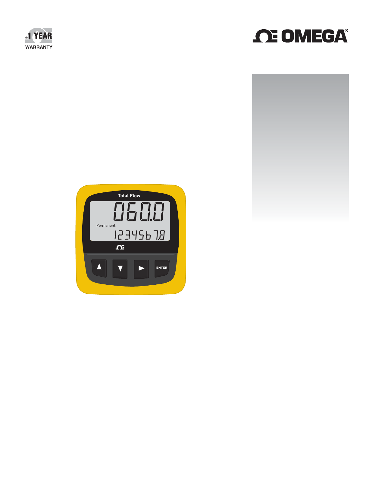
Flow Totalizer
Page 2

omega.com [email protected]
Servicing North America:
U.S.A. Omega Engineering, Inc.
Headquarters: Toll-Free: 1-800-826-6342 (USA & Canada only)
Customer Service: 1-800-622-2378 (USA & Canada only)
Engineering Service: 1-800-872-9436 (USA & Canada only)
Tel: (203) 359-1660 Fax: (203) 359-7700
e-mail: [email protected]
For Other Locations Visit omega.com/worldwide
The information contained in this document is believed to be correct, but OMEGA accepts no liability for any errors it contains, and reserves
the right to alter specifications without notice.
Page 3
OMEGA FPM-5750 Flow Totalizer Instructions
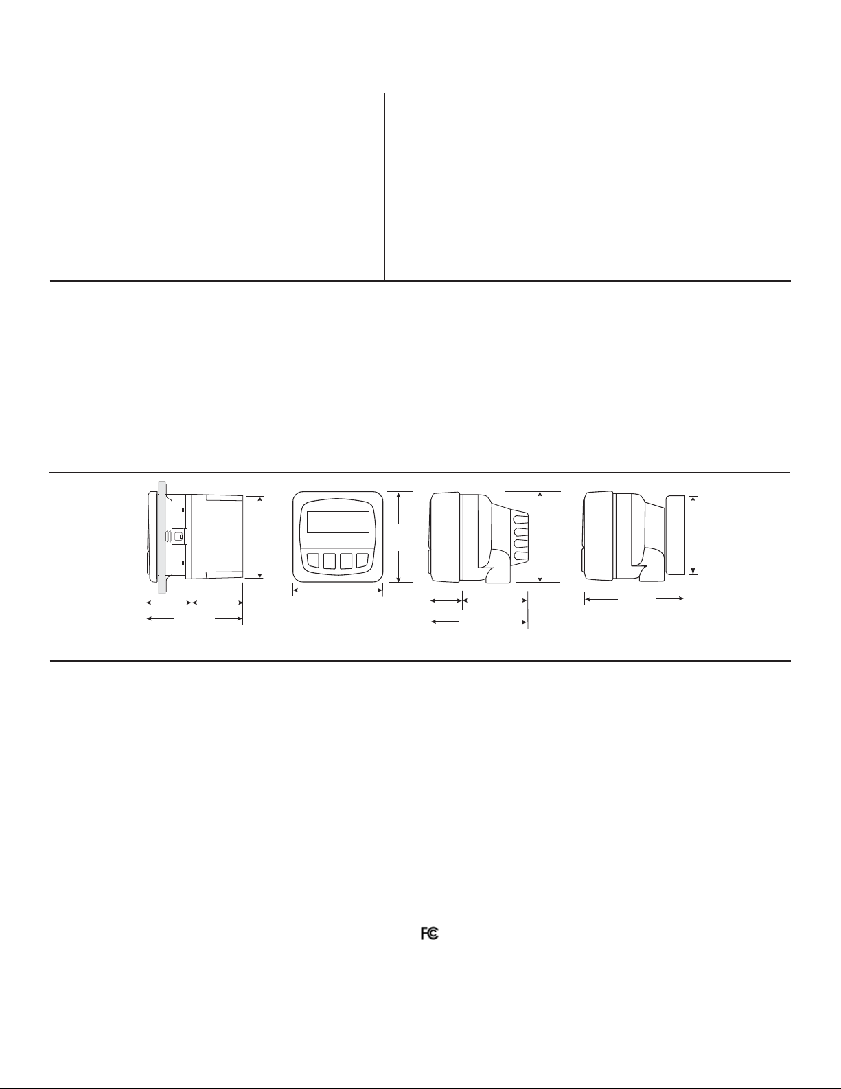
Integral Mount
96 mm
(3.8 in.)
96 mm
(3.8 in.)
FRONT VIEW
106 mm
(4.2 in.)
82 mm
(3.2 in.)
Universal Mount
92 mm
(3.6 in.)
97 mm
(3.8 in.)
56 mm
(2.2 in.)
41 mm
(1.6 in.)
Optional
Rear
Cover
Panel Mount
SIDE VIEW
102 mm
(4.0 in.)
42 mm
(1.7 in.)
60 mm
(2.3 in.)
96 mm
(3.8 in.)
Topic: Page
1. Description 1
2. Specifi cations 1
3. Installation 2
4. Wiring 4
5. Battery Installation and Replacement 4
6. Operation 5
7. Security Code 6
8. Totalizer operation 7
9. Automatic Calibration 9
Topic: Page
10. Flow K-Factor 10
11. Total K-Factor 11
12. Time Base 12
13. Decimal Point Placement 13
14. Speed 14
15. Sensitivity 15
16. Troubleshooting 16
17. Flow and Totalizer K-Factor selection 16
18. K-Factor Charts 17
19. Ordering Information 20
1. Description
The OMEGA FP-5750 Flow Totalizer is a battery-powered instrument capable of providing uninterrupted fl ow and total volume
information for 4 years and beyond. Unique features of the FPM-5750 include:
• Easy setup and display selection with 4-button keypad
• User selectable security access to prevent unwanted programming changes.
• Displays fl ow rate from 0.001 to 9999 engineering units with an auto-ranging decimal point.
• Three totalizers, one permanent and two that are independently resettable.
• Displays elapsed time between operating periods.
• Integral mount and panel mount options.
• 3.6 V Lithium batteries last 4 years nominal in most applications.
• Non-volatile memory stores all programming and totalizer values even when batteries are removed.
Dimensions
2. Specifi cations
General
Compatibility: OMEGA FP-8501, FP-5200,
FP-5000 Series sensors
Input Frequency Range: 1 to 400 Hz
Accuracy: ±0.5% of reading
Enclosure:
• Rating: NEMA 4X/IP65 (front panel)
• Dimensions: 1/4 DIN (96 mm x 96 mm x 50 mm)
(3.8 in. x 3.8 in. x 2.0 in.)
• Case material: PBT resin
• Keypad material: Sealed 4-key silicon rubber
Display: LCD type
• 4-digit upper line: Flow rate
• 8-digit lower line: Three totalizer options:
Permanent Totalizer for life of instrument
Totalizer 1: resettable from keypad or remote 30 m (100 ft)
Totalizer 2: resettable with security code only
• Display Contrast: Automatic
Electrical:
• Battery: Two 3.6V Lithium thionyl chloride, AA-size
(Use SAFT LS14500 Lithium Batteries or Equivalent Only)
• Sensor power output: +3.6 VDC @ 20 μA
• Battery life: 4 years nominal @ 50 °C (122 °F)
• Low Battery indication: Battery symbol on LCD display
Environmental:
• Operating Temperature: -10 °C to 65 °C (14 °F to 149 °F)
• Storage Temperature: -40 °C to 100 °C (-40 °F to 212 °F)
• Relative Humidity: 0 to 95% Non-condensing
Shipping Weight: 0.5 kg (1.1 lbs.)
Quality Standards:
• CE
• Manufactured under ISO 9001 for Quality, ISO 14001
for Environmental Management and OHSAS 18001 for
Occupational Health and Safety.
Declaration of Conformity according to FCC Part 15
This device complies with Part 15 of the FCC rules.
Operation is subject to the following two conditions:
(1) This device may not cause harmful interference, and,
(2) This device must accept any interference received,
including interference that may cause undesired operation.
1Omega FPM Series Flowmeter
Page 4
3. Installation
Flow
Totalizer
(FP-5750)
Integral
adapter Kit
(FP-90IM)
Integral
Flow Sensor
(FP-85XX Series)
OMEGA
Fittings
Integral Mount
Universal
Adapter Kit
(FP-90UM)
Terminal Cover
(4-3111)
Liquid-tight Connector
(3-9000.392-1)
Flow
Totalizer
(FP-5750)
Integral
Flow Sensor
(FP-85XX Series)
OMEGA
Fittings
Integral
Adapter kit
(FP-90IM)
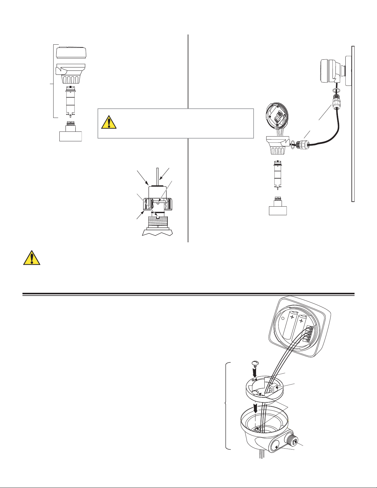
3.1 Integral Installation with Field Mount Totalizer
HAND-TIGHTEN THE THREADED NUT ONTO THE
INSTALLATION FITTING. DO NOT USE TOOLS!
DO NOT USE THREAD SEALANT OR LUBRICANTS
ON THE FITTING THREADS OR THE SENSOR CAP.
3.3 Plastic Sensor Installation Tips
black
conduit
• Lubricate O-rings with a non-
cap
petroleum based, viscous lubricant
(grease) compatible with the system.
• Using an alternating/twisting motion,
lower the sensor into the fi tting,
notch
making sure the installation arrows
on the black cap are pointing in the
direction of fl ow.
• Engage one thread of the sensor
cap then turn the sensor until the
sensor
cap
alignment tab is seated in the fi tting
notch.
sensor
bale
tab
3.2 Remote Field Mount On Wall
The parts identifi ed in Bold
type are required for this
installation. Other parts are
shown for reference only.
Use 2-conductor shielded
cable no more than 30 m
(100 ft.) long.
Chemical Compatibility Warning
The retaining nuts of paddlewheel sensors and Magmeters are not designed for prolonged contact with aggressive substances.
Strong acids, caustic substances and solvents or their vapor may lead to failure of the retaining nut, ejection of the sensor and
loss of the process fl uid with possibly serious consequences, such as damage to equipment and serious personal injury. Retaining nuts
that may have been in contact with such substances e.g. due to leakage or spilling, must be replaced.
3.4 Conduit Base Assembly Detail
1. Insert the wires from the sensor through the yellow conduit base and
locking ring.
2. Insert the locking ring into the conduit base, aligning it so that the
square tab is close to the conduit ports.
3. Insert the mounting screw into the conduit base so the head of the
screw presses down on the locking ring when tightened.
4. Connect sensor wires to the terminal connections on the integral
totalizer or terminal cover.
5. Remove the plastic pull tabs protecting the batteries, this will cause
the totalizer unit to power up.
6. For remote assembly, connect output wires to terminal cover output.
7. Route the output wires through the conduit port in the conduit base.
Conduit
Base
FP-5750
Flow T otalizer
Mounting
Screw
Locking
Ring
5
Kit
Do not use this hole.
Square T ab
The Mounting Screw for the
Locking Ring goes into the Conduit
Base (not the Locking Ring) -- the
screw head rests on the lip of the
Locking Ring.
Use a liquid-tight connector or conduit connector to prevent moisture
from entering the assembly.
8. Place totalizer or cover onto conduit base and twist to lock in place.
2 Omega FPM Series Flowmeter
Conduit
Base
Sensor wires
Conduit
Ports
Page 5
92 x 92 mm
(3.62 x 3.62 in.)
Panel cutout
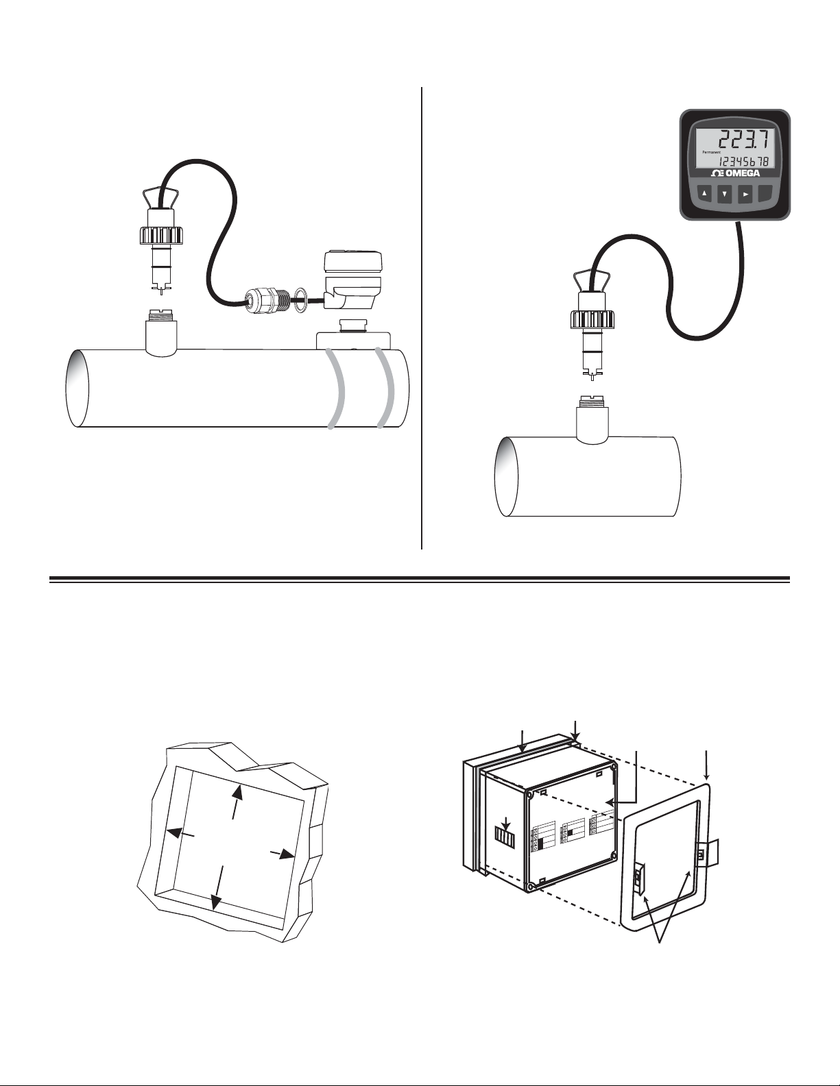
3.5 Remote Field Mount on Pipe 3.6 Remote Installation with Panel Mount Totalizer
The parts identifi ed in Bold type are required for this installation.
Other parts are shown for reference only.
Use 2-conductor shielded cable no more than 30 m (100 ft.) long.
Standard Mount
Paddlewheel
(FP-5300 Series)
OMEGA
Fittings
Universal
Mounting Kit
(FP-90UM)
Flow
Totalizer
(FP-5750)
NOTE: Pipe straps
not included
The parts identifi ed in Bold type are required for this installation.
Other parts are shown for reference only.
Total Flow
Totalizer
Panel Mount
(FP-5750-P)
ENTER
Standard Mount
Paddlewheel
(FP-5300 Series)
OMEGA
Fittings
3.7 Panel Mount Installation Detail
• The FP-5750-P Panel-mount Totalizer is a standard 1/4 DIN package. Use a 92x92 mm punch tool to make the panel cutout.
• Minimum spacing of 25 mm (1 in.) between panel units is recommended.
gasket
latch
panel
mounting
terminals
nd
Sensr G
(SHIELD)
7
Sensr IN
(RED)
6
Output -
Pwr
System
Loop -
2
Pwr
System
Loop +
1
Sensr V+
4
K)
(BLAC
5
Output +
3
bracket
Panel Mount
Installation Detail
quick-clips
3Omega FPM Series Flowmeter
Page 6
1
2
3
4
5
6
+
-
+
-
R
E
D
#1 #2
Totalizer 1
Remote reset
Connect shield
to Ground wire
Splice BLK and SHLD
together outside of terminal
B
L
A
C
K
S
H
I
E
L
D
51
525
CAUTION
When replacing batteries,
remove and replace
one battery at a time
Remove and replace
this battery first.
1
2
3
4
5
6
Note: Lithium Batteries
Dispose of properly!
Replace with 3.6 V Lithium battery
+ +
- -
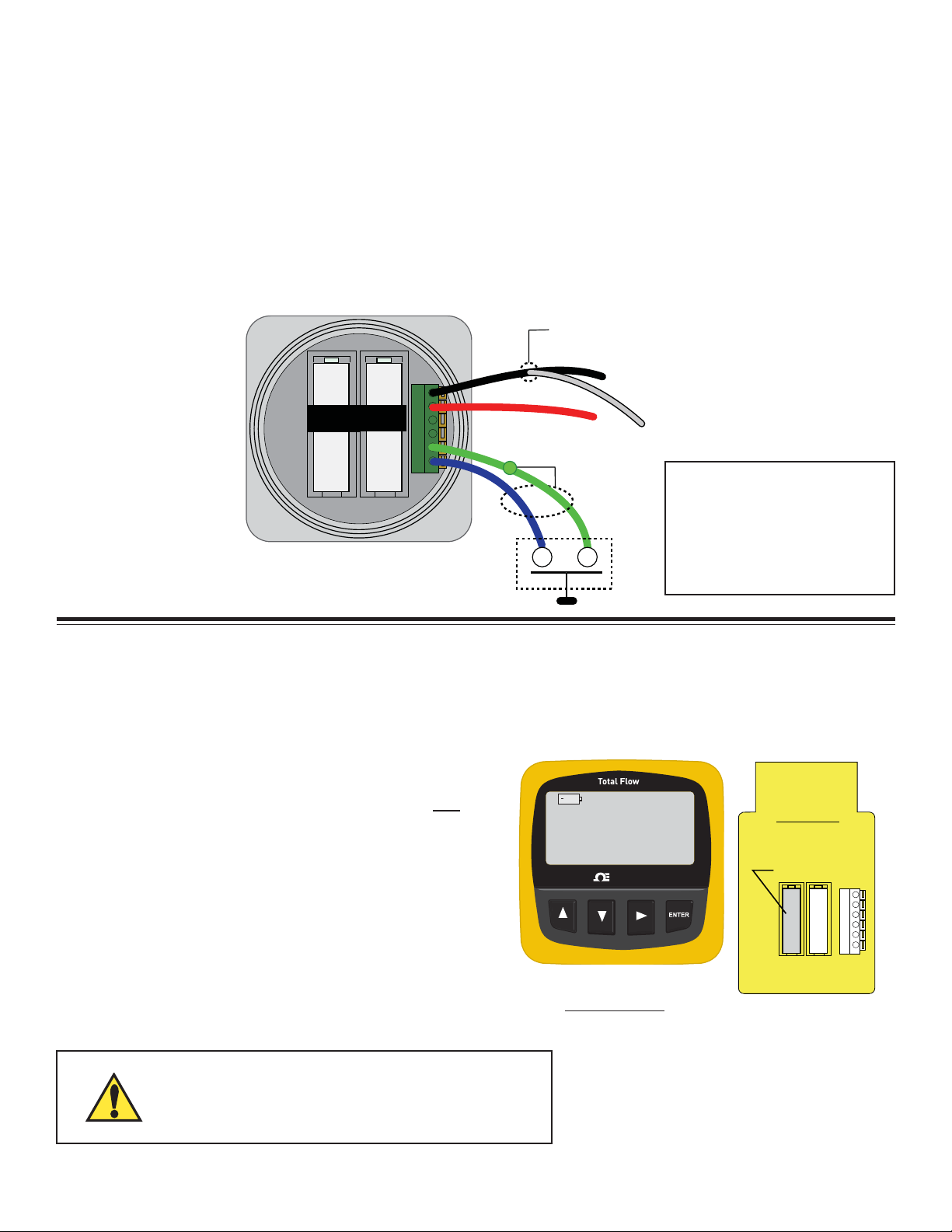
4. Wiring
• The wiring is identical for the panel mount and the fi eld mount versions of the totalizer.
• Only one wire should be inserted into a terminal. Splice double wires outside the terminal.
• External Reset for Total #1: Use no more than 30 m (100 ft.) of 2-conductor twisted-pair cable connected to a dry contact (for
example, an ordinary door-bell button or relay contact).
• Only Totalizer #1 can be reset by the external connection.
• Total #1 will not be displayed unless it is the standard totalizer selection.
Instructions
1. Remove 10 mm (3/8 in.) of insulation from sensor cable conductors.
2. Press down on orange lever to open terminal.
3. Insert wire into terminal until it hits bottom.
4. Release the lever to secure wire.
Sine wave Input Wiring
Use this wiring scheme for
OMEGA models FP-8501,
FP-5200, and FP-5000
Series sensors.
Terminal Function
1 Signal Ground
2 Sensor signal
3 Open Collector Signal
4 DC Power to sensor
5 Ground
6 Ext. Reset
5. Battery Installation and Replacement
Two 3.6V Lithium thionyl chloride batteries, AA-size are installed in with the totalizer.
NOTE: The FP-5750 WILL NOT OPERATE with standard 1.5 V alkaline batteries.
USE 3.6 V SAFT LS14500 LITHIUM BATTERIES OR EQUIVALENT ONLY!
• Remove pull tabs from the batteries to power up the FP-5750.
• Observe polarity! Note that both batteries face the same direction.
• When the “low battery” indicator appears on the display, both
batteries should be replaced within 90 days.
• Remove and replace battery #1 fi rst, then remove and replace
battery #2.
This ensures that all settings and totalizer values are saved.
• If the low battery symbol reappears for more than 10 seconds after
installing new batteries, one battery is reversed, or battery #2 was
installed before battery #1.
• Secure the batteries by fastening the hook-and-loop straps.
Shipping Notice:
If the battery pull tabs have been removed, remove the batteries from the totalizer prior to shipping.
Dispose of the batteries in accordance with the local regulations.
4 Omega FPM Series Flowmeter
DISPOSE OF EXPENDED BATTERIES PROPERLY!
Lithium batteries contain hazardous chemicals. Dispose of
batteries according to local regulation.
OMEGA
Page 7
6. Operation
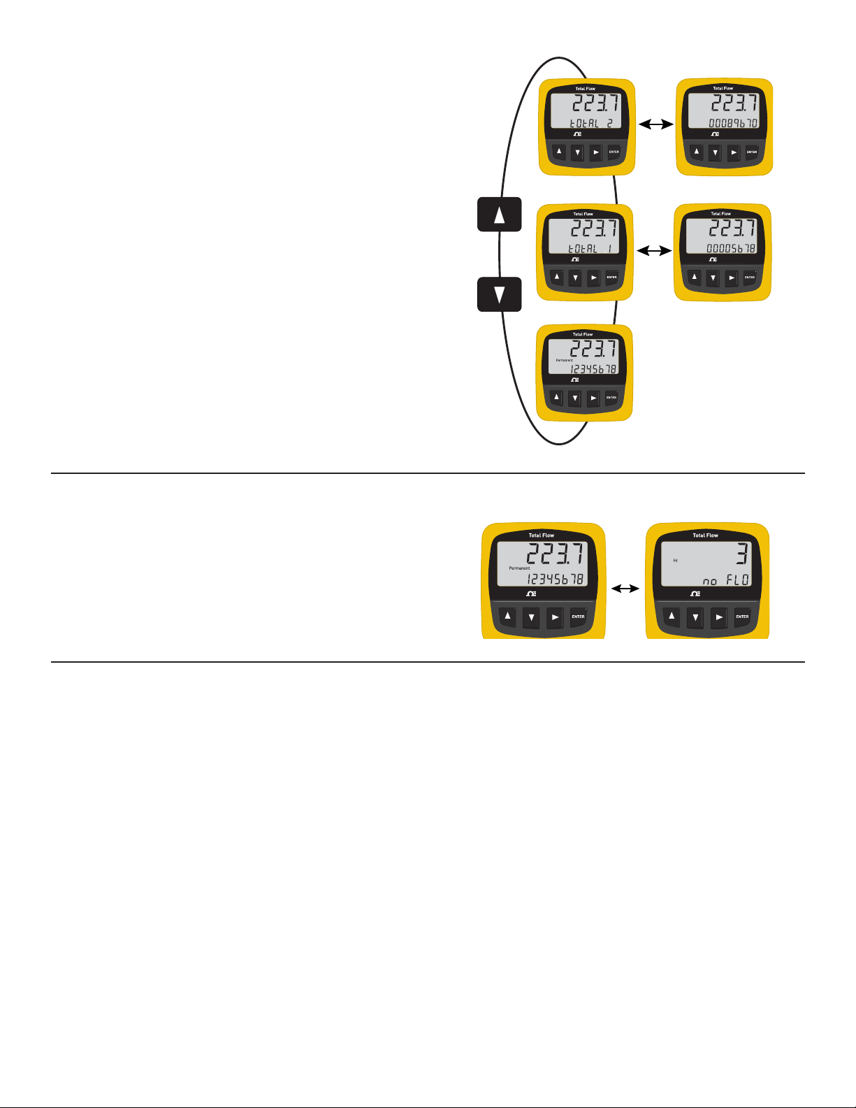
The FPM-5750 display shows the fl ow rate in large numerals and
a totalizer value in smaller numerals. Any one of three different
totalizers can be selected as the standard display (See section 8
for detailed information on the totalizers).
Press the UP or DOWN keys to scroll through the totalizer values
during normal operation.
OMEGA
OMEGA
6.1 No Flow and ELAPSED TIME Display
If the fl ow stops, the Totalizer displays the number of hours since
fl ow was last detected. This display will alternate with the normal
FLOW RATE and standard TOTAL display every fi ve seconds.
Any movement of the rotor in the pipe will reset the ELAPSED
TIME display.
OMEGA
OMEGA
Illustrated: No fl ow for 3 hours
OMEGA
5 sec.
OMEGA
OMEGA
6.2 Standard Menu Settings
Totalizers are shipped from the factory with these standard settings:
Function: Factory set: Description:
AUTO CALIBRATION No setting; See section 9 for detailed information.
FLOW K-Factor 60 Number of sensor pulses per volumetric unit; Refer to sensor manual.
TOTAL K-Factor 1 Set the number of volumetric units per totalizer count; see section 11.
TIMEBASE Minutes Select fl ow rate in seconds, minutes, hours or days. Section 12.
DECIMAL XXX.X Set the maximum decimal resolution. Section 13.
SPEED 30 s Zero to 120 seconds averaging stabilizes readings in erratic fl ow conditions. Section 14.
SENSITIVITY 6 Momentarily overrides SPEED when fl ow rate changes signifi cantly. Section 15.
SECURITY CODE 0-0-0-0 Set a private code to prevent tampering. Section 7.
DEFAULT TOTALIZER Permanent Select from three totalizer options. Section 8.
TOTALIZER #2 RESET Reset Totalizer #2 after entering the security code. Section 8.3.
5Omega FPM Series Flowmeter
Page 8
OMEGAOMEGA
OMEGAOMEGA
Enter Security Code
OMEGAOMEGA
OMEGAOMEGA
OMEGAOMEGA
OMEGAOMEGA
OMEGAOMEGA OMEGAOMEGA OMEGAOMEGA
OMEGAOMEGA
OMEGAOMEGA
2s
1
2 3 4 5
6 7 8
3X
3X
7. Security Code
OMEGAOMEGA
OMEGAOMEGA
OMEGAOMEGA
OMEGAOMEGA
OMEGAOMEGA
OMEGAOMEGA
1
2
3
4
5
2s
3X
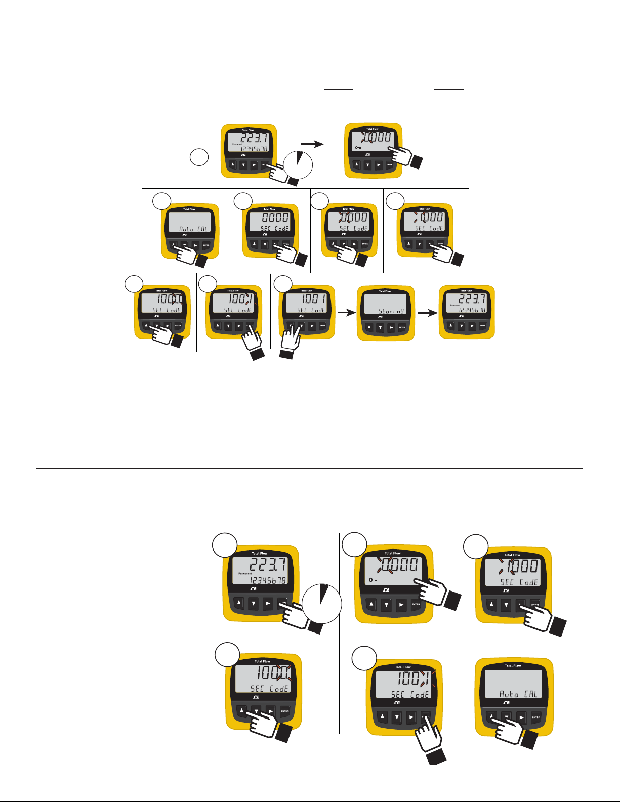
The security code prevents unauthorized tampering with calibration and operational settings in the FP-5750 Series.
The factory standard code is 0-0-0-0. Change the code to any 4-digit number by following these steps:
Example: Change the security code from the factory standard 0-0-0-0 to custom setting 1-0-0-1
NOTE:
Record and store your security code in a safe place!
1. Hold the ENTER key for 2 seconds, then enter the current
SECURITY CODE.
If working with a new unit, press the ENTER key again. The
display shows the fi rst menu item (Auto CAL)
2. Press the UP key three times to scroll to Sec Code.
3. Press RIGHT ARROW to edit the code.
The leading digit on the display will fl ash.
5. Press the RIGHT key three times to advance the fl ashing
element to the last digit.
6. Press the UP key one time to scroll the fl ashing digit to 1.
7. Press the ENTER key to complete the edit process.
8. Press the UP and DOWN keys together to exit the
Calibrate menu, store the new settings and return to normal
operation.
4. Press the UP key one time to scroll the fl ashing digit to 1.
7.1 Using the Security Code
A numerical code (0-0-0-0 to 9-9-9-9) must be entered before any of the menu selections can be modifi ed.
• The code is set at 0000 from the factory. To change the code, see section 7.1.
• To use the factory setting, complete step 1 and then step 9.
Example: Enter security code of 1001:
1. Hold the ENTER key for 2
seconds. The display shows
factory standard access code of
0000, with the fi rst zero fl ashing.
2. Press the UP key one time to scroll
the fl ashing zero to 1.
3. Press the RIGHT key three times
to advance the fl ashing character
to the last place value.
4. Press the UP key one time to scroll
the fl ashing zero to 1.
5. Press the ENTER key. The display
now shows the fi rst item in the
EDIT MENU.
6 Omega FPM Series Flowmeter
Page 9
8. Totalizer Setup and Operation
OMEGAOMEGA
OMEGAOMEGA
OMEGAOMEGA
OMEGAOMEGA
OMEGAOMEGA
OMEGAOMEGA
OMEGAOMEGA
Enter Security Code
2s
1
OMEGAOMEGA
OMEGAOMEGA
2
3
OMEGAOMEGA
OMEGAOMEGA
OMEGAOMEGA
OMEGAOMEGA
4
5
OMEGAOMEGA
6
5 m
OMEGAOMEGA
OMEGAOMEGA
2X
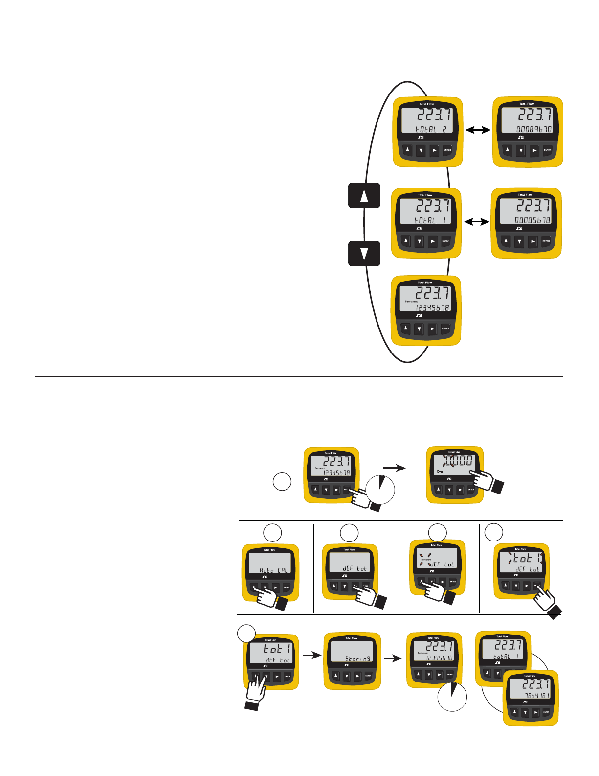
During normal operation the FP-5750 displays the fl ow rate and one selected totalizer value. Any one of the three totalizers can be set
as the standard display: The other two totalizers can be viewed by pressing the keypad. The display will automatically return to the
standard selection after fi ve minutes.
The PERMANENT Totalizer is identifi ed directly on the LCD.
• This totalizer records all input from the time of manufacture.
• The permanent totalizer cannot be reset.
• Application: The permanent totalizer should be selected as the standard
if the system is monitored and the total recorded regularly.
Total 1 (tot1) can be reset from the keypad or from the external RESET
(see Wiring, section 4) without the security code.
• Total 1 is identifi ed by a fl ashing display every six seconds.
• Application: Use Total 1 to measure water usage for a recurring
period, as for a daily discharge volume.
Total 2 (tot2) can be reset only by entering the security code in the
calibration menu.
• Total 2 is identifi ed by a fl ashing display every six seconds.
• Application: Use Total 2 for extended measurement periods, as for a
monthly discharge volume.
8.1 Defi ne the Standard Totalizer
Any of the three totalizer functions can be set as the standard display, or select SCROLL to display all three totalizers in sequence.
The PERMANENT totalizer is the factory standard selection.
Example: Change the standard Totalizer from PERMANENT to Totalizer #1
1. Press ENTER key for 2 seconds. (Display
shows security key symbol and 0-0-0-0. Set
security code and press ENTER key.)
2. Press UP key two times.
Display shows "def tot" and the
"PERMANENT" label.)
3. Press RIGHT ARROW key. (PERMANENT
label begins to fl ash.)
4. Press UP key one time. Display changes to
fl ashing "tot 1".
5. Press ENTER key to complete the edit
process.
6. Press UP and DOWN keys together to store
new value in the memory.
The display will show "Storing" for a few
seconds, then return to normal operation.
NOTE: The new totalizer selection will
appear after a 5 minute delay.
7Omega FPM Series Flowmeter
Page 10
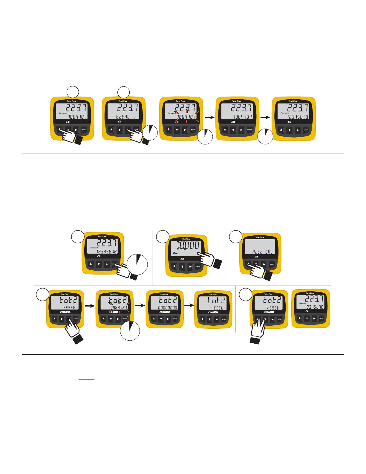
8.2 Resetting Totalizer 1
OMEGAOMEGA
OMEGAOMEGA
OMEGAOMEGA
2
OMEGAOMEGA
OMEGAOMEGA
5m
8s
1
2s
OMEGAOMEGA
OMEGAOMEGA
Enter Security Code
2s
1
OMEGAOMEGA
2 3
4
OMEGAOMEGA
8s
5
1. Press UP key to scroll to "total 1" display.
2. Press and hold the RIGHT arrow key until the display shows "rst tot1".
The totalizer will fl ash for 8 seconds and then it will automatically reset to 00000000.
• Press the ENTER key while the display is fl ashing to reset immediately.
• While the total value is fl ashing, you can cancel the reset by pressing UP and DOWN keys together.
• Totalizer #1 will be displayed for 5 minutes after the reset, then the standard totalizer selection will return.
• Press the UP or DOWN key to scroll back to the standard display immediately.
External Reset: See section 4: Wiring for information on resetting Totalizer #1 remotely from up to 30 meters distance. NOTE: When
Total #1 is reset from an external switch, the display will not show totalizer #1 unless it has been set as the standard totalizer.
8.3 Resetting Totalizer 2
Totalizer #2 can be reset ONLY by entering the security code.
1. Press ENTER key for 2 seconds. (Display shows security key symbol and 0-0-0-0)
2. Set the security code in the fl ashing display and then press the ENTER key.
3. Press UP key one time. (Display shows "tot2 reset")
4. Press RIGHT ARROW key. The totalizer value will begin fl ashing.
The totalizer will automatically reset to 00000000 in 8 seconds.
While the display is fl ashing, you can cancel the reset by pressing UP and DOWN keys together.
5. Press UP and DOWN keys together to return to normal operation.
8.4 Saving Totalizer Values
To conserve battery life, totalizer values are stored in the memory every 12 hours. If both batteries are removed from the unit, the
totalizers retain the last saved values, so the unit may lose several hours of data.
To prevent this loss, enter the security code, then enter any menu item and store the setting.
Whenever the FP-5750 stores a setting, it also stores all current totalizer data:
1. Enter the security code.
2. Press the UP key to scroll to the last item in the menu (DEFAULT TOTALIZER)
3. Press the RIGHT key to enter the edit mode (fl ashing display mode)
4. Press the ENTER key to retain the current settings.
5. Press the UP and DOWN keys simultaneously to initiate the "Storing" function.
The batteries can now be removed and replaced without losing any totals.
8 Omega FPM Series Flowmeter
Page 11
OMEGAOMEGA
OMEGAOMEGA
OMEGAOMEGA
OMEGAOMEGA
OMEGAOMEGA
OMEGAOMEGA
OMEGAOMEGA
OMEGAOMEGA
8
7
Enter security code
Signet Total Flow
Signet Total Flow
Signet Total Flow
1
2
3 5 6 4
OMEGAOMEGA
OMEGAOMEGA
OMEGAOMEGA
OMEGAOMEGA
2 s
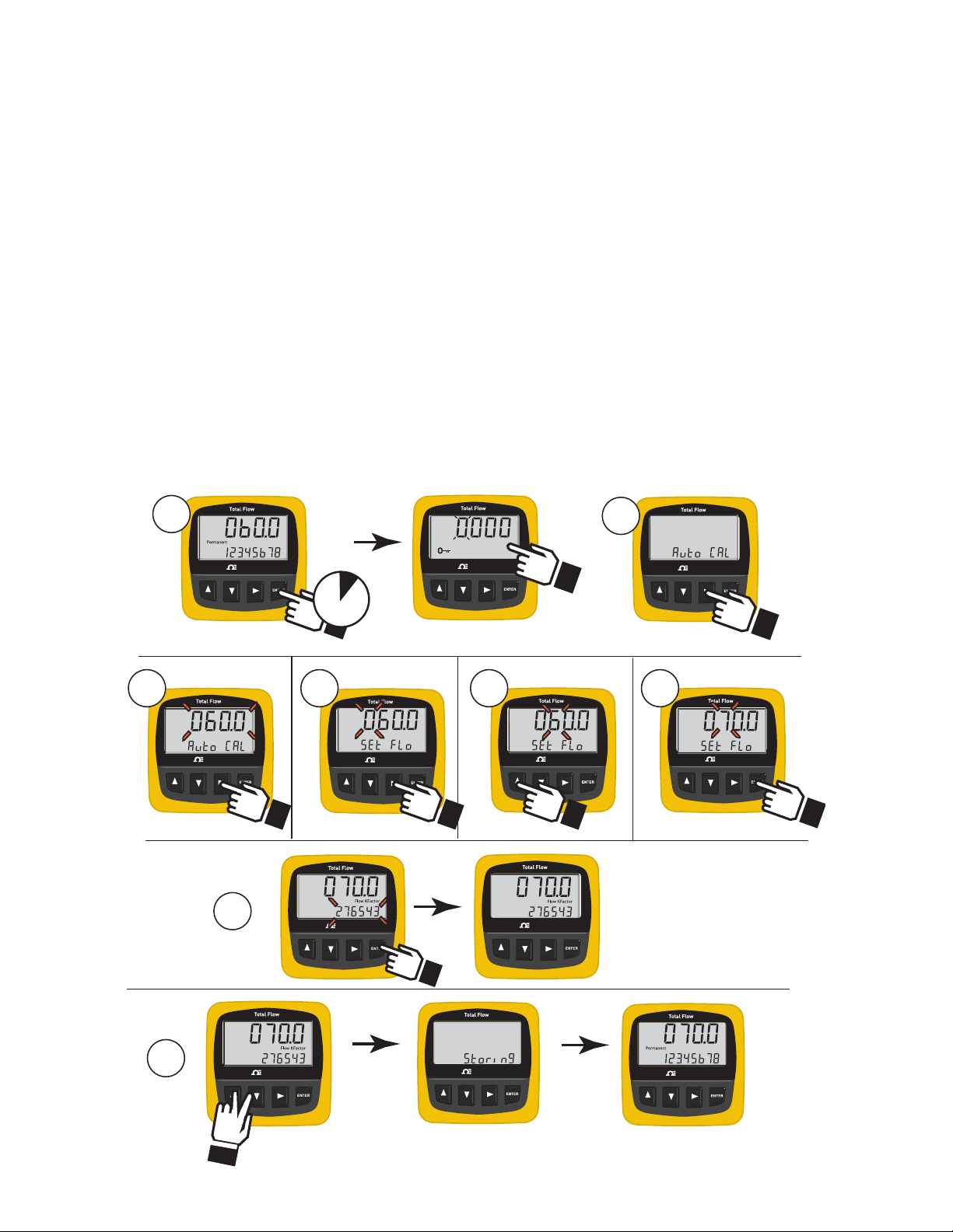
9. AutoCAL Calibration
The AutoCAL feature allows theTotalizer to be adjusted to match the fl ow rate to any external reference.
• Flow in the pipe should be as stable as possible for best results.
• If the fl ow rate display is erratic, set the SPEED (section 14) to 120 seconds during the AutoCAL procedure.
• The timebase on the reference meter must be the same as the FP-5750 Totalizer.
Example: The Totalizer fl ow rate shows 60 GPM, while an external reference indicates a true fl ow rate of 70 GPM.
Change the fl ow rate from 60 GPM to 70 GPM using AutoCAL.
1. Hold the ENTER key for 2 seconds, then enter the SECURITY CODE.
AutoCAL is the fi rst item in the menu.
2. Press the RIGHT key to select the AutoCAL function.
The display will show AutoCAL and the current fl ow rate will be fl ashing.
3. Press the RIGHT key again to change the fl ow rate. The display shows "Set Flo" and the fi rst digit of the fl ow rate will begin
fl ashing.
5. Press the RIGHT key to advance the fl ashing element to the "6".
5. Press the UP key one time to change the "6" to "7".
6. Press the ENTER key to complete the automatic calibration process.
The display shows a new K-Factor with the fi rst digit fl ashing. This K-Factor is based on the change in fl ow rate.
7. Press the ENTER key again to accept the new value.
NOTE: If the display shows "ERR SetFlo" the procedure was unsuccessful because the calculated K-Factor is less than 0.001 or
greater than 999999. Verify the fl ow rate and start the AutoCAL procedure from step 1.
8. Press UP and DOWN keys together to store the new value in the memory.
The display will show "storing" for a few seconds, then return to normal operation.
9Omega FPM Series Flowmeter
Page 12
10. Flow K-Factor
The K-Factor is the number of pulses generated by the fl ow sensor for each measure of water that moves past the sensor.
Your fl ow sensor manual contains K-Factor data in terms of U.S. gallons and liters.
Locate the K-Factor that matches your pipe size and material.
If necessary, the K-Factor can be converted into other units of measure.
The minimum K-Factor value is 0.001, maximum value is 999999.
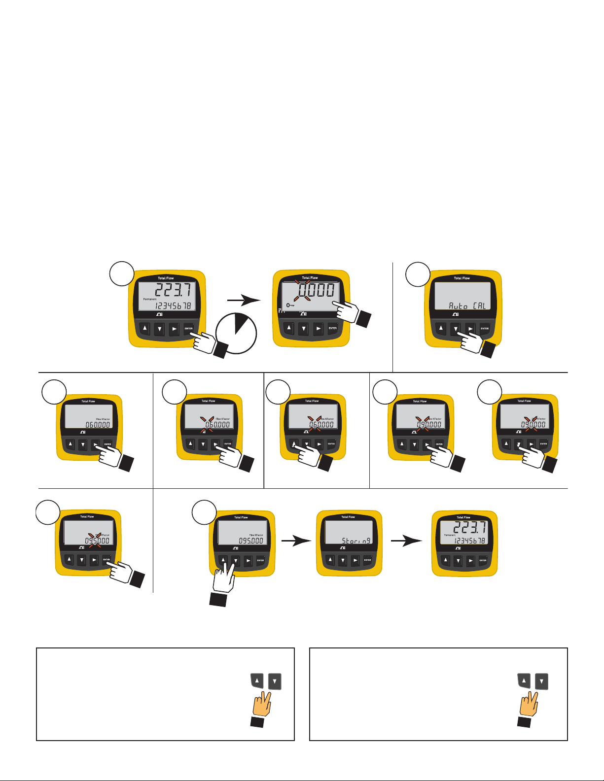
Example: Change the Flow K-Factor from 060.000 to 095.000
1. Hold the ENTER key for 2 seconds, then enter the SECURITY CODE (factory default is 0-0-0-0).
The display shows the fi rst item in the menu (AutoCAL).
2. Press the DOWN key to scroll to the Flow K-Factor. (The display shows the current K-Factor setting.)
3. Press the RIGHT key to select the Flow K-Factor for editing. (The fi rst element of the K-Factor will begin fl ashing.)
4. Press the RIGHT key 1 time to advance the fl ashing element to the "6".
5. Press the UP key three times to change the "6" to "9".
6. Press the RIGHT key to advance the fl ashing element to the "0."
7. Press the DOWN key fi ve times to change the "0" to "5".
8. Press the ENTER key to return to the CALIBRATE menu.
9. Press UP and DOWN keys together to store the new value and return to normal operation.
1
OMEGA
2 s
3 4 5
OMEGA
ENTER
OMEGA
*
8 9
OMEGA
OMEGA
OMEGA
Enter security code
OMEGA
3X
OMEGA
2
OMEGA
***
6 7
OMEGA
OMEGA
OMEGA
3X
**
Exit Without Changing?
*
As long as any element is fl ashing, you can abort
the change and return to the original value by
pressing UP and DOWN keys simultaneously.
10 Omega FPM Series Flowmeter
Finished Editing?
**
Press the UP and DOWN keys
simultaneously from the main menu to
return to normal operation.
Page 13
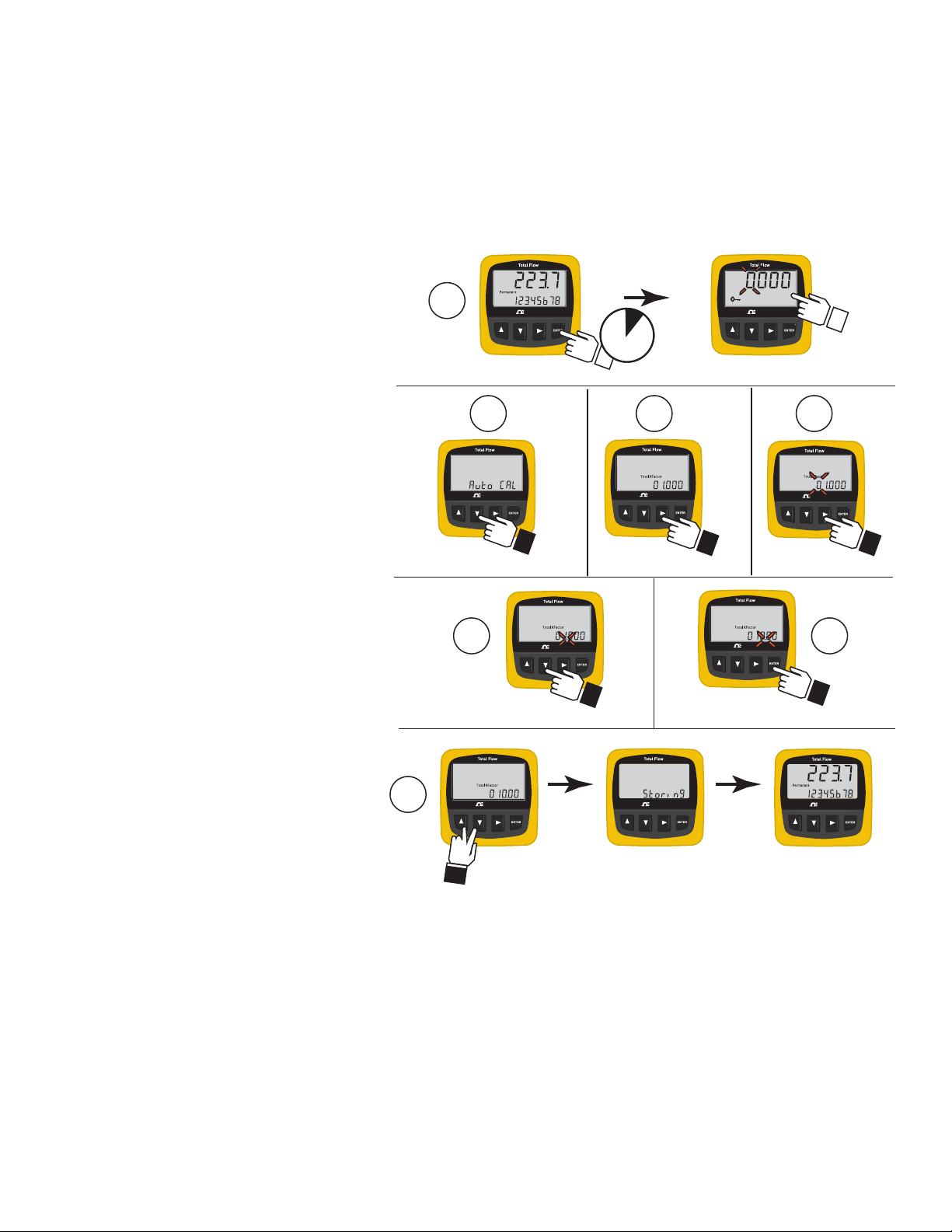
11. Total K-Factor
The TOTAL K-Factor is a multiple of the FLOW K-Factor. Use it to program the incremental count size of the totalizer.
For example, if the fl ow RATE registers in liters per minute, the totalizer may be set to 1 (factory standard), so it counts in 1-liter
increments, or it may be set to 1000, so it counts in 1 kiloliter (1m3) increments.
By converting the Flow K-Factor, the totalizer can also be set to count in other engineering units.
See sec. 17: "Flow and Total K-Factor selection" for additional information about Total K-Factor adjustments.
Example: Change the totalizer from 1-kilolitre increments to count in 10-kilolitre increments.
1. Hold the ENTER key for 2 seconds, then enter the SECURITY CODE.
The display shows the fi rst item in the menu,
AutoCAL.
2. Press the DOWN key two times to scroll to the
Total K-Factor.
3. Press the RIGHT key to select the Total
K-Factor for editing.
The fi rst element of the Total K-Factor will begin
fl ashing.
4. Press the RIGHT key six times to advance the
fl ashing element to the decimal point.
5. Press the DOWN key one time to move the
decimal point one position to the right.
6. Press the ENTER key to return to the menu.
7. Press UP and DOWN keys together to exit the
menu and return to normal operation.
The display shows "Storing" for a few seconds,
then returns to the normal operating display.
1
OMEGA
ENTER
2 3
OMEGA
2x
2 s
OMEGA
OMEGA
Enter security code
4
OMEGA
6x
7
5
OMEGA
OMEGA
OMEGA
OMEGA
6
OMEGA
11.1 Adjusting the Flow K-Factor
If the Totalizer yields a consistent error, make corrections by either using the AutoCal function (section 9) or by manually adjusting the
Flow K-Factor by the percentage of error.
A smaller K-Factor increases the fl owrate, while larger K-Factors reduce the fl ow rate.
Example:
• The Flow K-Factor is set at 480.19 pulses per gallon.
• The totalizer registers 10 gallons when the actual volume is known to be 11 gallons.
• The error is 1 gallon divided by 10 gallons , or -10%. (The totalizer is counting 10% low, and the fl ow rate is reading 10% slow.)
• Reduce the Flow K-Factor by 10%: 480.19 - 10% = 432.17.
• Change the Flow K-Factor to 432 pulses per gallon.
The result: The totalizer must count 10% fewer pulses from the fl ow sensor to register one Gallon, so both the totalizer and the fl ow rate
will increase by 10%.
11Omega FPM Series Flowmeter
Page 14
12. Time Base
OMEGAOMEGA
OMEGAOMEGA
OMEGAOMEGA
OMEGAOMEGA
OMEGAOMEGA
OMEGAOMEGAOMEGAOMEGA
1
2
3 4 5
6
Enter security code
3x
2x
2 s
OMEGAOMEGA
OMEGAOMEGA
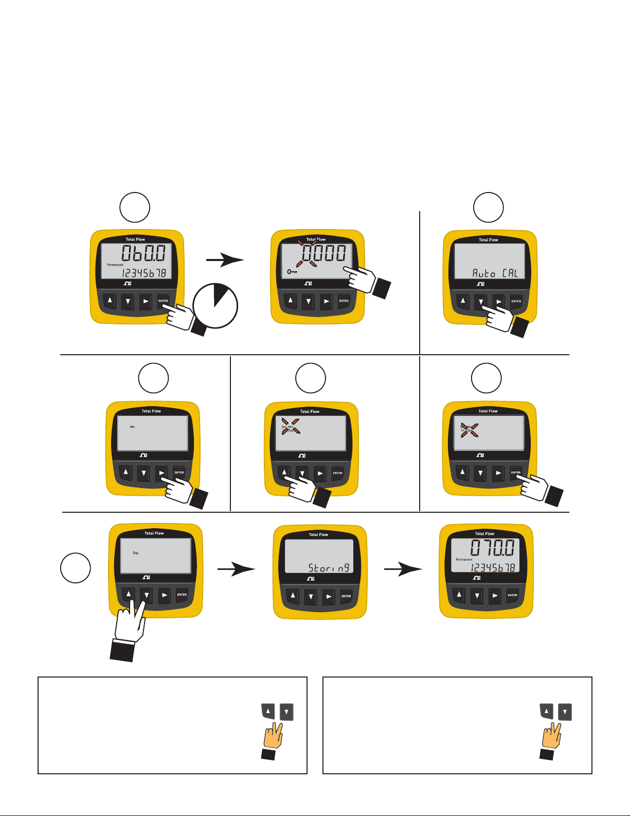
Select the timebase for the fl ow rate. The available selections are seconds, minutes, hours or days.
Example: Change the Timebase from MINUTES (factory standard) to DAYS
1. Hold the ENTER key for 2 seconds, then enter the SECURITY CODE.
The display shows the fi rst item in the CALIBRATE menu, AutoCAL.
2. Press the DOWN key three times to scroll to the Timebase.
3. Press the RIGHT key to select the Timebase for editing.
4. Press the UP key two time to scroll from MIN to DAY.
5. Press the ENTER key to return to the menu.
6. Press UP and DOWN keys together to exit the menu and return to normal operation.
The display shows "Storing" for a few seconds, then returns to the normal operating display.
**
*
**
*
Exit Without Changing?
*
As long as any element is fl ashing, you can abort
the change and return to the original value by
pressing UP and DOWN keys simultaneously.
12 Omega FPM Series Flowmeter
Finished Editing?
**
Press the UP and DOWN keys
simultaneously from the main menu to
return to normal operation.
Page 15
OMEGAOMEGA
OMEGAOMEGA
OMEGAOMEGA
OMEGAOMEGA
OMEGAOMEGA
OMEGAOMEGA OMEGAOMEGA
1
6
2
Enter Security code
3
4
5
2 s
4x
OMEGAOMEGA
OMEGAOMEGA
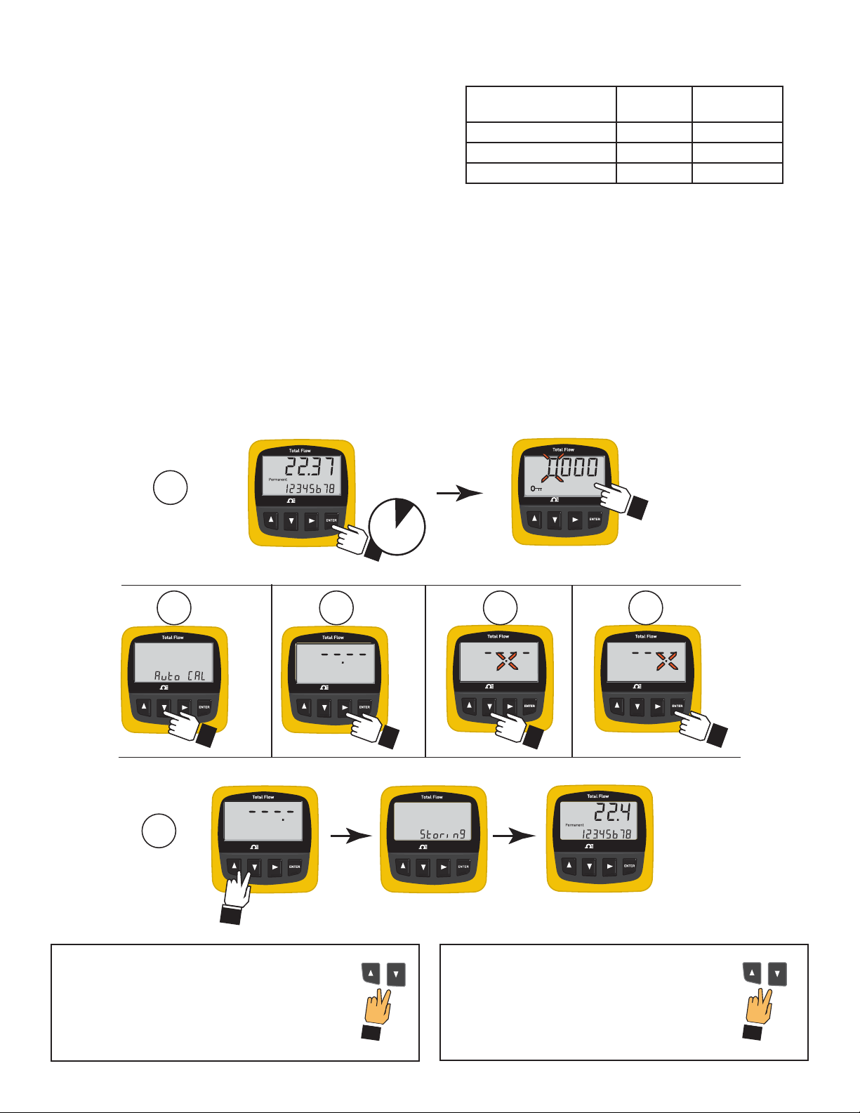
13. Decimal Point for Flow Display
Select the maximum decimal resolution for the fl ow rate display.
The available selections are hundredths (xx.xx), tenths (xxx.x) or
whole numbers only (xxxx.). The decimal will auto-range down to this
setting.
• If the decimal is set to whole numbers, the fl ow rate display will
not auto-range.
• If the decimal is set to tenths, the fl ow rate display will show
tenths up to 999.9, then the auto-range will switch to whole
numbers (1000 to 9999.)
• If the decimal is set to hundredths, the fl ow rate display will show
hundredths up to 99.99, then tenths from 100.1 to 999.9, then
whole numbers to 9999.
Example: Change the maximum decimal display from
hundredths to tenths:
1. Hold the ENTER key for 2 seconds, then enter the SECURITY
CODE.
The display shows the fi rst item in the menu, AutoCAL.
2. Press the DOWN key four times to scroll to the Decimal setting.
The display shows four dashes and the current decimal setting.
3. Press the RIGHT key to select the decimal for editing.
The decimal point will begin to fl ash.
Available
Display Selections
hundredths (XX.XX) 10.55 10.55
tenths (XXX.X) 10.55 10.6
whole numbers (XXXX.) 10.55 11
4. Press the DOWN key one time to move the fl ashing decimal
from hundredths to tenths.
5. Press the ENTER key to return to the menu.
The decimal will stop fl ashing.
6. Press UP and DOWN keys together to exit the menu and
return to normal operation.
The display shows "Storing" for a few seconds, then returns
to the normal operating display.
Your
Flow Rate
Will read on
display as:
**
Exit Without Changing?
*
As long as any element is fl ashing, you can abort
the change and return to the original value by
pressing UP and DOWN keys simultaneously.
Finished Editing?
**
Press the UP and DOWN keys
simultaneously from the main menu to
return to normal operation.
*
13Omega FPM Series Flowmeter
Page 16
14. Speed
OMEGAOMEGA
OMEGAOMEGA
OMEGAOMEGA
OMEGAOMEGA
OMEGAOMEGA
OMEGAOMEGA
OMEGAOMEGA
OMEGAOMEGA
OMEGAOMEGA
1
6
2 s
Enter Security code
2 3 4
ENTER
5x
SPEED averaging serves to smooth out fl uctuations in the fl ow rate that may be caused by inadequate straight pipe runs after pumps,
valves, and elbows in the pipe. The selections are 0, 7, 15, 30, 60 and 120 seconds. The factory standard setting is 30 seconds.
• Use faster (0 s - 30 s) averaging for well-established, stable fl ow conditions.
• Use slower (60 s -120 s) averaging if the fl ow conditions are unstable.
Note: While the SPEED setting helps to smooth out the fl uctuations caused by piping conditions, it also causes a delay in showing
actual changes in fl ow rate. The SENSITIVITY function (section 15) is designed to help offset this effect.
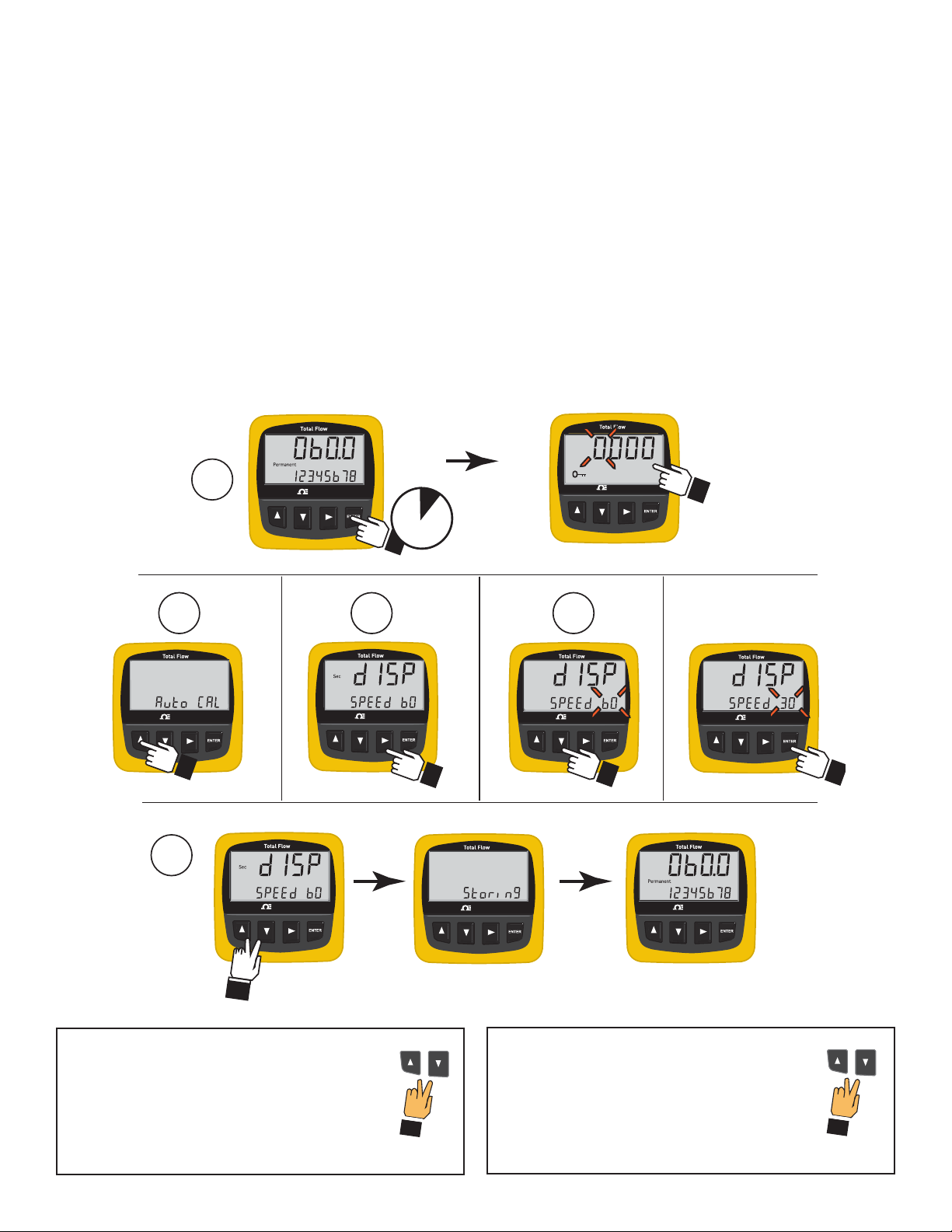
Example: Change the SPEED setting from 60 seconds to 30 seconds.
1. Hold the ENTER key for 2 seconds, then enter the SECURITY CODE.
The display shows the fi rst item in the CALIBRATE menu, AutoCAL.
2. Press the DOWN key fi ve times to scroll to DISP SPEED.
The display shows DISP SPEED, the "sec" annunciator, and the current speed setting.
3. Press the RIGHT key to select the Display speed for editing.
The current speed selection begins fl ashing.
4. Press the DOWN key one time to scroll from 60 seconds to 30 seconds.
5. Press the ENTER key to return to the menu.
6. Press UP and DOWN keys together to exit the menu and return to normal operation.
The display shows "Storing" for a few seconds, then returns to the normal operating display.
Exit Without Changing?
**
*
As long as any element is fl ashing, you can abort
the change and return to the original value by
pressing UP and DOWN keys simultaneously.
Finished Editing?
**
*
Press the UP and DOWN keys
simultaneously from the main menu to
return to normal operation.
14 Omega FPM Series Flowmeter
Page 17
15. Sensitivity
10 s2 s 20 s 30 s 40 s 50 s 60 s 70 s
No SPEED, no SENSITIVITY
SPEED only
SPEED and SENSITIVITY
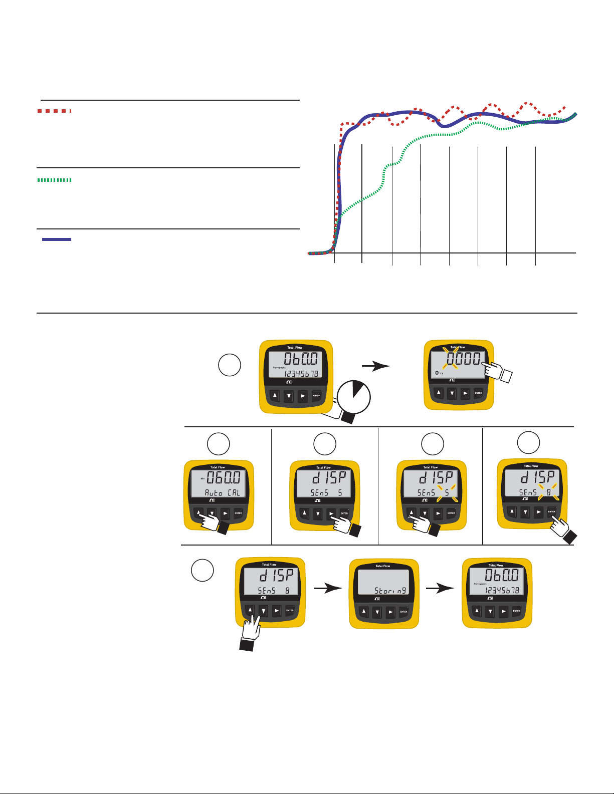
The SENSITIVITY setting determines how the FPM-5750 responds to sudden surges in the fl ow rate. It "overrides" the SPEED function
just long enough to allow an actual change in fl ow rate to be displayed, then resumes the averaging. The result is a smooth fl ow
display and a quick response to large shifts in the fl ow rate.
With SPEED averaging set to 0 (zero) and with SENSITIVITY set
to zero, the fl ow rate may be very unstable. This line represents
the actual output of the fl ow sensor as it responds to unstable
fl ow conditions in the pipe.
With SPEED set to 60 seconds and SENSITIVITY still set to zero
the fl ow rate is stabilized, but a sharp change in fl ow rate is not
represented for 60 seconds or longer (dotted green line).
With SPEED at 60 seconds and SENSITIVITY set to 6, the fl ow
rate is stabilized, while the sudden shift in fl ow is refl ected very
quickly (dotted blue line).
NOTE: The SENSITIVITY function is ineffective if the SPEED function is set to zero (seconds).
Example: Change the SENSITIVITY from 5 to 8
1. Hold the ENTER key for
2 seconds, then enter the
SECURITY CODE.
The display shows the fi rst
item in the menu, AutoCAL.
2. Press the UP key once to
scroll to SENSITIVITY.
The display shows DISP
SENS and the current
sensitivity setting.
3. Press the RIGHT key to select
the SENSITIVITY for editing.
The current SENSITIVITY
setting begins fl ashing.
4. Press the UP key three times
to scroll from 5 to 8.
5. Press the ENTER key to
return to the menu.
6. Press UP and DOWN keys
together to exit the menu and
return to normal operation.
The display shows "Storing"
for a few seconds, then
returns to the normal
operating display.
6
2
OMEGA
1
OMEGA
OMEGA
3
OMEGA
2 s
OMEGA
Enter Security code
4
OMEGA
3x
OMEGA
5
OMEGA
ENTER
OMEGA
15Omega FPM Series Flowmeter
Page 18
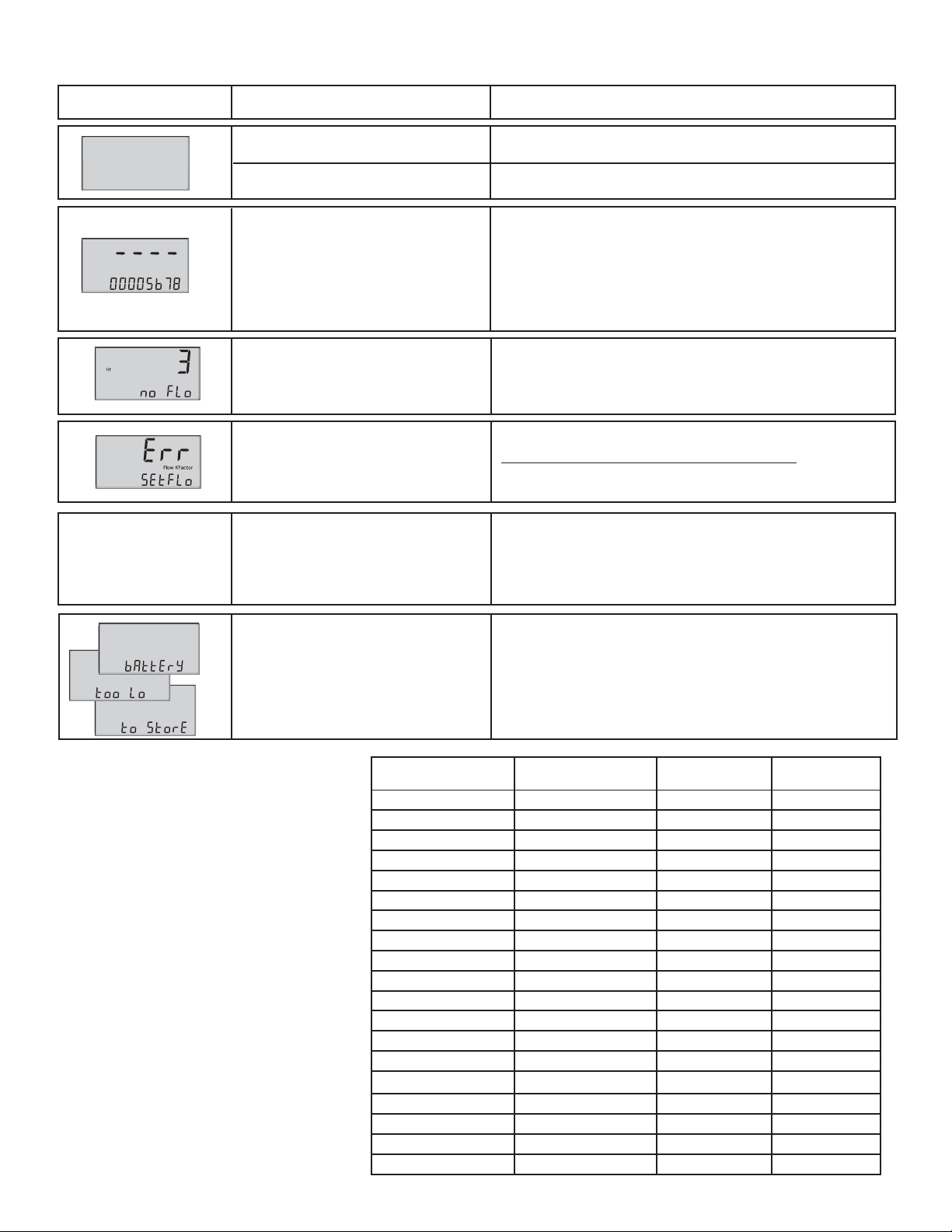
16. Troubleshooting
Display Condition Suggested Solutions
Batteries are dead or missing
Probable Cause
Replace both batteries.
Pull tabs have not been removed. Remove plastic pull tabs protecting the batteries.
1. Reduce the fl ow rate.
2. Change the Timebase to a smaller value.
The fl ow rate is greater than
“9999”
(Example: Change from “Day” to “Hour”.)
3. Change the fl ow units to a larger measure.
(Example: Change from “Liters” to “Gallons”.)
NOTE: If the Flow K-Factor is changed, be sure to make a
corresponding change to the TOTAL K-Factor.
FP-5750 is not receiving a signal
from the fl ow sensor.
In AutoCal, the calculated K-Factor
is outside the range of the FP-
1. There is no fl ow in the pipe.
2. Flow sensor is not turning due to blockage or damage.
3. Sensor wiring is loose or incorrect.
Press RIGHT key to start AutoCAL procedure again.
Make sure that the fl ow rate entered is accurate.
5750. (less than 0.001 or greater
than 99999)
1. Correct piping layout to provide more straight pipe upstream
The fl ow rate display
is erratic and non-linear
Usually caused by inadequate
straight pipe run upstream of
sensor.
of sensor.
2. Set the SPEED to higher setting to average out the
fl uctuations caused by piping conditions. (see Speed,
section 14)
Both batteries are too depleted
to safely store settings.
17. Flow and Total K-Factor Selection
Pages 17-19 provide K-Factors for the
OMEGA FP-8501, FP-5200, and FP-5000
Series fl ow sensors. Use this table to
convert the K-Factor to other units of
measure, and to set the Total K-Factor.
NOTE:
• The maximum K-Factor is 999999.
• The minimum K-Factor is 0.001.
16 Omega FPM Series Flowmeter
“If you want the
FLOW RATE to read in:”
Liters Liters K(Liter) 1
Liters Kiloliters K(Liter) 1000
Liters cubic meters K(Liter) 1000
cubic meters cubic meters K(Liter) x 1000 1
cubic meters Megaliters K(Liter) x 1000 1000
Kiloliters Kiloliters K(Liter) x 1000 1
Kiloliters Megaliters K(Liter) x 1000 1000
Megaliters Megaliters K(Liter) x 1 000 000 1
U.S. gallons U.S. gallons K(gal) 1
U.S. gallons U.S. gallons x 1000 K(gal) 1000
U.S. gallons cubic feet K(gal) 7.4805
U.S. gallons acre-inches K(gal) 27154
U.S. gallons acre-feet K(gal) 325848
U.S. gallons Kiloliters K(gal) 264.2
acre-inches acre-inches K(gal) x 27154 1
acre-inches acre-feet K(gal) x 27154 12
acre-feet acre-feet K(gal) x 325848 1
acre-feet acre-inches K(gal) x 325848 0.083
cubic feet cubic feet K(gal) x 7.4805 1
Replace battery #1, then replace battery #2.
and you want the
TOTALIZER to count in:
“Set the Flow
K-Factor to:”
“and set the Total
K-Factor to:”
Page 19
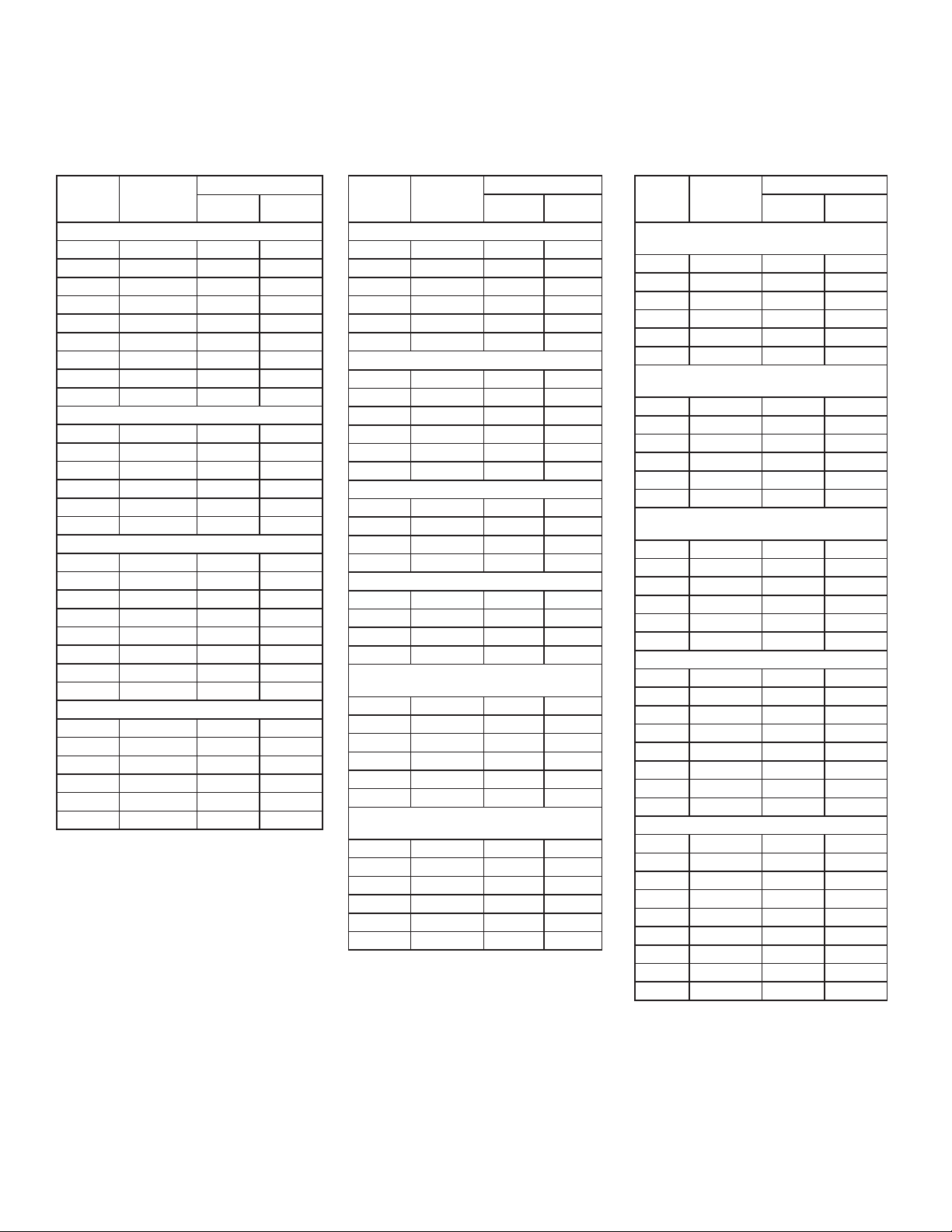
18. K-Factor Charts
18.1 FP-8501 and FP-5000 Series Paddlewheel Flow Sensor
The following calibration data is reprinted for your convenience
from the OMEGA FP-8501 and FP-5000 Series Flow sensor
instruction manuals.
PIPE
SIZE
(IN.)
SCH 80 PVC TEES FOR SCH 80 PVC PIPE
1/2 FP-5305M 520.12 137.42
3/4 FP-5307M 297.52 78.61
1 FP-5310M 172.07 45.46
1-1/4 FP-5312M 91.54 24.19
1-1/2 FP-5315M 62.22 16.44
2 FP-5320M 36.32 9.60
2-1/2 FP-5325 21.833 5.7683
3 FP-5330 13.541 3.5775
4 FP-5340 7.6258 2.0147
SCH 80 CPVC TEES FOR SCH 80 CPVC PIPE
1/2 FP-5305CM 520.12 137.42
3/4 FP-5307CM 297.52 78.61
1 FP-5310CM 172.07 45.46
1-1/4 FP-5312CM 91.54 24.19
1-1/2 FP-5315CM 62.22 16.44
2 FP-5320CM 36.32 9.60
SCH 80 PVC SADDLES FOR SCH 80 PVC PIPE
2 FP-5320S 32.480 8.5812
2-1/2 FP-5325S 21.833 5.7683
3 FP-5330S 13.541 3.5775
4 FP-5340S 7.6258 2.0147
6 FP-5360S 4.1623 1.0997
8 FP-5380S 2.3705 0.6263
10 FP-5310S 1.5300 0.4042
12 FP-5382S 1.0600 0.2801
SCH 80 PVC SADDLE ON SCH 40 PVC PIPE
2 FP-5320S 27.350 7.2259
2-1/2 FP-5325S 18.874 4.9866
3 FP-5330S 12.638 3.3389
4 FP-5340S 6.7282 1.7776
6 FP-5360S 3.7297 0.9854
8 FP-5380S 2.1527 0.5688
FITTING
FP-51XX, 53XX
U.S. GAL LITERS
PIPE
SIZE
(IN.)
CARBON STEEL TEES ON SCH 40 PIPE
1/2 FP-5305CS 370.20 97.808
3/4 FP-5307CS 212.06 56.027
1 FP-5310CS 141.14 37.289
1-1/4 FP-5312CS 60.655 16.025
1-1/2 FP-5315CS 45.350 11.982
2 FP-5320CS 26.767 7.0717
STAINLESS STEEL TEES ON SCH 40 PIPE
1/2 FMG-5305 358.96 94.838
3/4 FMG-5307 202.61 53.530
1 FMG-5310 127.14 33.590
1-1/4 FMG-5312 61.910 16.357
1-1/2 FMG-5315 40.410 10.676
2 FMG-5320 22.300 5.8917
GALVANIZED IRON TEES ON SCH 40 PIPE
1 FP-5310G 104.54 27.619
1-1/4 FP-5312G 62.979 16.639
1 1/2 FP-5315G 46.688 12.335
2 FP-5320G 29.459 7.7832
BRONZE TEES ON SCH 40 PIPE
1 FP-5310BR 104.54 27.619
1-1/4 FP-5312BR 62.979 16.639
1-1/2 FP-5315BR 46.688 12.335
2 FP-5320BR 29.459 7.7832
COPPER TEE FITTINGS ON COPPER PIPE
SCH K
1/2 FP-5305BR 443.21 117.10
3/4 FP-5307BR 212.16 56.052
1 FP-5310BR 127.18 33.600
1-1/4 FP-5312BR 88.218 23.307
1-1/2 FP-5315BR 56.962 15.049
2 FP-5320BR 29.370 7.7595
COPPER TEE FITTINGS ON COPPER PIPE
SCH L
1/2 FP-5305BR 414.41 109.49
3/4 FP-5307BR 191.09 50.485
1 FP-5310BR 119.84 31.662
1-1/4 FP-5312BR 85.451 22.576
1-1/2 FP-5315BR 55.160 14.573
2 FP-5320BR 28.605 7.5575
FITTING
FP-51XX, 53XX
U.S. GAL LITERS
PIPE
SIZE
(IN.)
STAINLESS STEEL WELDOLETS ON SCH
40 PIPE
2-1/2 FMG-5325 18.800 4.9670
3 FMG-5330 12.170 3.2153
4 FMG-5340 6.9600 1.8388
5 FMG-5350 5.2600 1.3897
6 FMG-5360 3.6900 0.9749
8 FMG-5380 2.1300 0.5627
CARBON STEEL WELDOLETS ON SCH 40
PIPE
2-1/2 FP-5325CS 18.800 4.9670
4 FP-5340CS 6.9600 1.8388
5 FP-5350CS 5.2600 1.3897
6 FP-5360CS 3.6900 0.9749
10 FP-5381CS 1.3500 0.3567
12 FP-5382CS 0.9600 0.2536
COPPER/BRONZE BRAZOLETS ON SCH
40 PIPE
2-1/2 FP-5325BR 18.800 4.9670
3 FP-5330BR 12.170 3.2153
4 FP-5340BR 6.9600 1.8388
5 FP-5350BR 5.2600 1.3897
6 FP-5360BR 3.6900 0.9749
8 FP-5380BR 2.1300 0.5627
SCH 80 IRON SADDLES ON SCH 80 PIPE
2 FP-5320GI 32.360 8.5495
2-1/2 FP-5325GI 22.220 5.8705
3 FP-5330GI 13.420 3.5456
4 FP-5340GI 7.6600 2.0238
5 FP-5350GI 5.8600 1.5482
6 FP-5360GI 4.0900 1.0806
8 FP-5380GI 2.3300 0.6156
12 FP-5382GI 1.0600 0.2801
SCH 80 IRON SADDLE ON SCH 40 PIPE
2 FP-5320GI 26.820 7.0859
2-1/2 FP-5325GI 18.800 4.9670
3 FP-5330GI 11.990 3.1678
4 FP-5340GI 6.8500 1.8098
5 FP-5350GI 5.3300 1.4082
6 FP-5360GI 3.7600 0.9934
8 FP-5380GI 2.1300 0.5627
10 FP-5381GI 1.3500 0.3567
12 FP-5382GI 0.9600 0.2536
FITTING
FP-51XX, 53XX
U.S. GAL LITERS
17Omega FPM Series Flowmeter
Page 20
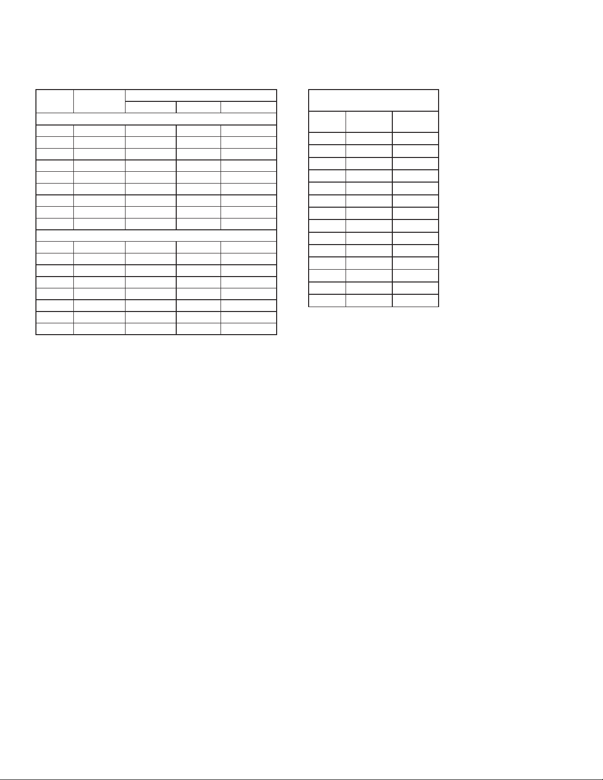
Paddlewheel Flow Sensor (continued)
18.2 FP-5200 Series Flow Sensor18.1 FP-8501 and FP-5000 Series
The following data is reprinted from the OMEGA FP-5200
Series Flow Sensor manual for your convenience.
PIPE
SIZE
POLYPROPYLENE FITTINGS (DIN/ISO AND BS AND ANSI)
DN 25 FP-5110PO 141.18 37.300 198.150.524
DN 40 FP-5115PO 51.265 13.544 198.150.526
DN 50 FP-5120PO 29.596 7.8193 198.150.527
DN 65 FP-5125PO 20.658 5.4579 198.150.560
DN 80 FP-5130PO 13.330 3.5218 198.150.561
DN 100 FP-5140PO 8.7077 2.3006 198.150.562
DN 125 FP-5150PO 5.0667 1.3386 198.150.563
DN 150 FP-5160PO 3.6892 0.9747 198.150.564
DN 200 FP-5180PO 2.0398 0.5389 198.150.565
PVDF FITTINGS (DIN/ISO AND BS AND ANSI)
DN 15 FP-5105 420.87 111.19 198.150.529
DN 20 FP-5107 228.15 60.277 198.150.530
DN 65 FP-5125 18.067 4.7732 198.150.571
DN 80 FP-5130 12.357 3.2648 198.150.572
DN 100 FP-5140 8.0599 2.1294 198.150.573
DN 125 FP-5150 4.4312 1.1707 198.150.574
DN 150 FP-5160 3.2271 0.8526 198.150.575
DN 200 FP-5180 2.0360 0.5379 198.150.576
FITTING
U.S. GAL LITERS CODE
FP-51XX, 53XX
SCH 40S STAINLESS STEEL PIPE
PER ANSI B36.19
PIPE
SIZE
1/2. 873.03 230.66
3/4. 515.41 136.17
1. 266.17 70.322
1 1/4. 148.84 39.324
1 1/2. 107.98 28.528
2. 64.808 17.122
2 1/2. 44.685 11.806
3. 28.579 7.5506
4. 16.302 4.3070
5. 10.237 2.7046
6. 7.0057 1.8509
8. 3.9641 1.0473
10. 2.4690 0.6523
12. 1.6894 0.4463
PULSES/
U.S. GAL
PULSES/
LITER
18 Omega FPM Series Flowmeter
Page 21

Notes
19Omega FPM Series Flowmeter
Page 22
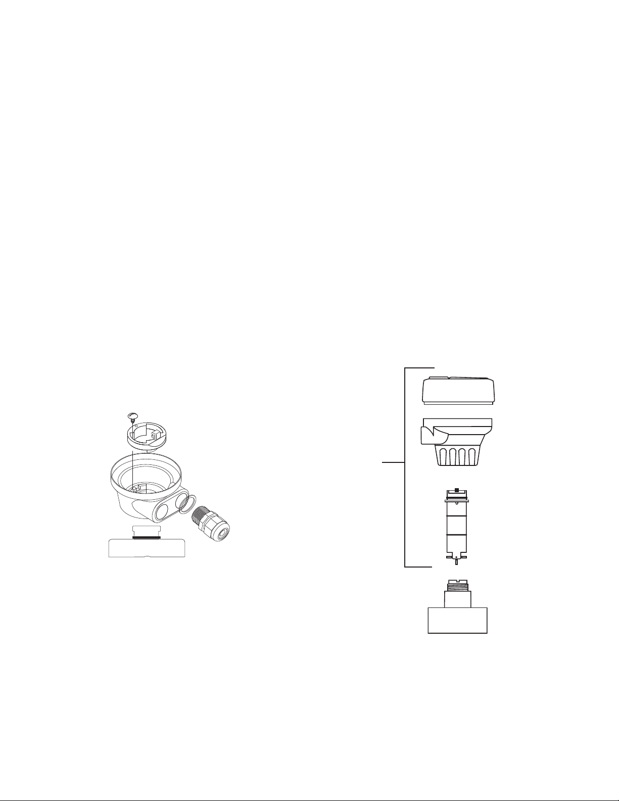
19. Ordering Information
Mfr. Part No. Description
FP-5750 Flow Totalizer
FP-5750-P Flow Totalizer, Panel Mount
Parts and Accessories
Mounting
FP-90IM Integral Mounting Kit
FP-90UM Universal mounting kit
FP-90-4X Splashproof rear cover for panel mount totalizer
FPM-5000-MB Surface mount bracket
FPM-5000-LTCK Liquid tight connector kit (includes 3 connectors)
Replacement parts for integral mount units
FP-8501 Sensor, Integral, Polypropylene, Titanium Rotor Pin, PVDF Rotor (black), 1/2 to 4 Inch Pipe
FP-8502 Sensor, Integral, Polypropylene, Titanium Rotor Pin, PVDF Rotor (black), 5 to 8 Inch Pipe
FP-8503 Sensor, Integral, PVDF (natural), PVDF (natural) Rotor Pin, PVDF Rotor (natural), 1/2 to 4 In. Pipe
FP-5100 Sensor, PVDF (natural), Hastelloy-C Rotor Pin, PVDF Rotor (natural), 1/2 to 4 Inch Pipe
FP-5101 Sensor, PVDF (natural), Hastelloy-C Rotor Pin, PVDF Rotor (natural), 5 to 8 Inch Pipe
FP-5300 Sensor, Polypropylene, Titanium Rotor Pin, PVDF Rotor (black), 1/2 to 4 Inch Pipe
FP-5301 Sensor, Polypropylene, Titanium Rotor Pin, PVDF Rotor (black), 5 to 8 Inch Pipe
FP-5302 Sensor, Polypropylene, Titanium Rotor Pin, PVDF Rotor (black) 10 to 36 Inch Pipe
FMK-515-3P3 Sensor, Wet-Tap, Polypropylene, Titanium Rotor Pin, PVDF Rotor (black), 1/2 to 4 Inch Pipe
FMK-515-3P5 Sensor, Wet-Tap, Polypropylene, Titanium Rotor Pin, PVDF Rotor (black), 10 to 36 Inch Pipe
PH-31542-TC Red Threaded Cap For In-Line Installations
Note: Use Saft LS14500 Lithium Batteries or equivalent ONLY.
FP-90UM
Universal mounting kit
Integral Mount
Flow
Totalizer
(FP-5750)
Integral
adapter Kit
(FP-90IM)
Integral
Flow Sensor
(FP-85XX Series)
OMEGA
Fittings
20 Omega FPM Series Flowmeter
Page 23

WARRANTY/DISCLAIMER
OMEGA ENGINEERING, INC. warrants this unit to be free of defects in materials and workmanship for a
period of 13 months from date of purchase. OMEGA’s WARRANTY adds an additional one (1) month
grace period to the normal one (1) year product warranty to cover handling and shipping time. This
ensures that OMEGA’s customers receive maximum coverage on each product.
If the unit malfunctions, it must be returned to the factory for evaluation. OMEGA’s Customer Service
Department will issue an Authorized Return (AR) number immediately upon phone or written request.
Upon examination by OMEGA, if the unit is found to be defective, it will be repaired or replaced at no
charge. OMEGA’s WARRANTY does not apply to defects resulting from any action of the purchaser,
including but not limited to mishandling, improper interfacing, operation outside of design limits,
improper repair, or unauthorized modification. This WARRANTY is VOID if the unit shows evidence of
having been tampered with or shows evidence of having been damaged as a result of excessive corrosion;
or current, heat, moisture or vibration; improper specification; misapplication; misuse or other operating
conditions outside of OMEGA’s control. Components in which wear is not warranted, include but are not
limited to contact points, fuses, and triacs.
OMEGA is pleased to offer suggestions on the use of its various products. However,
OMEGA neither assumes responsibility for any omissions or errors nor assumes liability for
any damages that result from the use of its products in accordance with information provided
by OMEGA, either verbal or written. OMEGA warrants only that the parts manufactured by the
company will be as specified and free of defects. OMEGA MAKES NO OTHER WARRANTIES OR
REPRESENTATIONS OF ANY KIND WHATSOEVER, EXPRESSED OR IMPLIED, EXCEPT THAT OF
TITLE, AND ALL IMPLIED WARRANTIES INCLUDING ANY WARRANTY OF MERCHANTABILITY
AND FITNESS FOR A PARTICULAR PURPOSE ARE HEREBY DISCLAIMED. LIMITATION OF
LIABILITY: The remedies of purchaser set forth herein are exclusive, and the total liability of
OMEGA with respect to this order, whether based on contract, warranty, negligence,
indemnification, strict liability or otherwise, shall not exceed the purchase price of the
component upon which liability is based. In no event shall OMEGA be liable for
consequential, incidental or special damages.
CONDITIONS: Equipment sold by OMEGA is not intended to be used, nor shall it be used: (1) as a “Basic
Component” under 10 CFR 21 (NRC), used in or with any nuclear installation or activity; or (2) in medical
applications or used on humans. Should any Product(s) be used in or with any nuclear installation or
activity, medical application, used on humans, or misused in any way, OMEGA assumes no responsibility
as set forth in our basic WARRANTY/DISCLAIMER language, and, additionally, purchaser will indemnify
OMEGA and hold OMEGA harmless from any liability or damage whatsoever arising out of the use of the
Product(s) in such a manner.
RETURN REQUESTS/INQUIRIES
Direct all warranty and repair requests/inquiries to the OMEGA Customer Service Department.
BEFORE RETURNING ANY PRODUCT(S) TO OMEGA, PURCHASER MUST OBTAIN AN AUTHORIZED
RETURN (AR) NUMBER FROM OMEGA’S CUSTOMER SERVICE DEPARTMENT (IN ORDER TO AVOID
PROCESSING DELAYS). The assigned AR number should then be marked on the outside of the return
package and on any correspondence.
The purchaser is responsible for shipping charges, freight, insurance and proper packaging to prevent
breakage in transit.
FOR WARRANTY RETURNS, please have the
following information available BEFORE contacting
OMEGA:
1. Purchase Order number under which the product
was PURCHASED,
2. Model and serial number of the product under
warranty, and
3. Repair instructions and/or specific problems
relative to the product.
OMEGA’s policy is to make running changes, not model changes, whenever an improvement is possible. This affords
our customers the latest in technology and engineering.
OMEGA is a registered trademark of OMEGA ENGINEERING, INC.
© Copyright 2016 OMEGA ENGINEERING, INC. All rights reserved. This document may not be copied, photocopied,
reproduced, translated, or reduced to any electronic medium or machine-readable form, in whole or in part, without the
prior written consent of OMEGA ENGINEERING, INC.
FOR NON-WARRANTY REPAIRS,
OMEGA for current repair charges. Have
the following information available BEFORE
contacting OMEGA:
1. Purchase Order number to cover the COST
of the repair,
2. Model and serial number of the product, and
3. Repair instructions and/or specific problems
relative to the product.
consult
Page 24

Where Do I Find Everything I Need for
Process Measurement and Control?
OMEGA…Of Course!
Shop online at omega.com
TEMPERATURE
Thermocouple, RTD & Thermistor Probes, Connectors, Panels & Assemblies
Wire: Thermocouple, RTD & Thermistor
Calibrators & Ice Point References
Recorders, Controllers & Process Monitors
Infrared Pyrometers
PRESSURE, STRAIN AND FORCE
Transducers & Strain Gages
Load Cells & Pressure Gages
Displacement Transducers
Instrumentation & Accessories
FLOW/LEVEL
Rotameters, Gas Mass Flowmeters & Flow Computers
Air Velocity Indicators
Turbine/Paddlewheel Systems
Totalizers & Batch Controllers
SM
pH/CONDUCTIVITY
pH Electrodes, Testers & Accessories
Benchtop/Laboratory Meters
Controllers, Calibrators, Simulators & Pumps
Industrial pH & Conductivity Equipment
DATA ACQUISITION
Communications-Based Acquisition Systems
Data Logging Systems
Wireless Sensors, Transmitters, & Receivers
Signal Conditioners
Data Acquisition Software
HEATERS
Heating Cable
Cartridge & Strip Heaters
Immersion & Band Heaters
Flexible Heaters
Laboratory Heaters
ENVIRONMENTAL
MONITORING AND CONTROL
Metering & Control Instrumentation
Refractometers
Pumps & Tubing
Air, Soil & Water Monitors
Industrial Water & Wastewater Treatment
pH, Conductivity & Dissolved Oxygen Instruments
M4209/0916
 Loading...