

Page 1
User’s Guide
Shop online at
omega.com
e-mail: [email protected]
For latest product manuals:
www.omegamanual.info
®
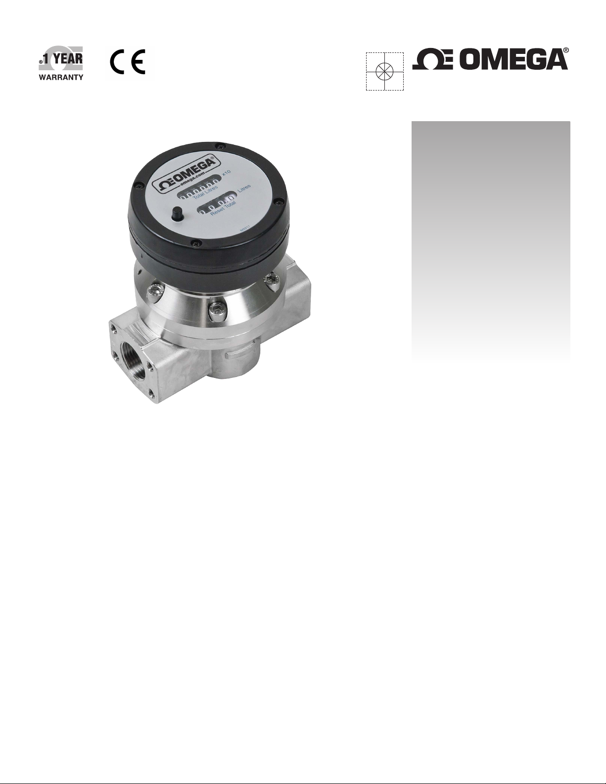
FPDM3000 Series
FPDM3200 Series
FPDM3300 Series
1/2" - 2" Oval Gear Flowmeter
w
ith Mechanical Register
Page 2

omega.com [email protected]
Servicing North America:
U.S.A.: Omega Engineering, Inc., One Omega Drive, P.O. Box 4047
Stamford, CT 06907-0047 USA
Toll-Free: 1-800-826-6342 (USA & Canada only)
Customer Service: 1-800-622-2378 (USA & Canada only)
Engineering Service: 1-800-872-9436 (USA & Canada only)
Tel: (203) 359-1660 Fax: (203) 359-7700
e-mail: [email protected]
For Other Locations Visit omega.com/worldwide
The information contained in this document is believed to be correct, but OMEGA accepts no liability for any errors it contains, and reserves
the right to alter specifications without notice.
WARNING: These products are not designed for use in, and should not be used for, human applications.
Page 3

index
Installation
Pre-installation checks
Operating Principle
Installation Procedure
Maintenance Procedure
Disassembly
Reassembly
Flowmeter Specifications
Flowmeter Specifications
Service
Troubleshooting Guide
………………………………………………………….
………………………………………………………….
………………………………………………………….
………………………………………………………….
………………………………………………………….
………………………………………………………….
………………………………………………………….
Page 3
Page 5
Page 5
Page 6
Page 6
Page 7-8
Page 8
Exploded Diagram
Wetted Parts
General
Pressure Drop Graphs
Dimensional Diagrams
………………………………………………………….
………………………………………………………….
………………………………………………………….
Page 9-10
Page 11-13 ………………………………………………………….
Page 14
Page 15-18
3
Page 4

To the Owner
PLEASE READ THIS SAFTEY INFORMATION CAREFULLY BEFORE USE.
Read and retain this instruction manual to assist you in the operation and maintenance of this product.
This Flow Meter has incorporated the oval rotor principal into its design. This has proven to be a reliable and
highly accurate method of measuring flow.
Exceptional repeatability and high accuracy over a wide range of fluid viscosities and flow rates are features of
the oval rotor design. With a low pressure drop and high pressure rating oval rotor flow meters are suitable for
both gravity and pump (in line) applications.
If you have any problems with the meter, refer to the maintenance and trouble shooting sections of this manual.
This manual contains connection and operating instructions for meters with Mechanical Displays
If you need further assistance, contact your local representative or distributor for advice.
IMPORTANT INFORMATION
FLUID COMPATABILITY
Before use, confirm the fluid to be
used is compatible with the meter. Refer to Industry fluid compatibility
charts or consult your local representative for advice.
STRAINER
To prevent damage from dirt or foreign matter it is recommended that a
Y or Basket type mesh strainer be
installed as close as
possible to the inlet side of the meter.
When a strainer is installed it
should be regularly inspected and
cleaned. Failure to keep the strainer
clean will dramatically effect flow meter performance.
Contact your local representative for advice.
AIR PURGE / LINE PRESSURE
To prevent damage caused by air purge
slowly fill the meter with fluid.
To reduce pressure build-up turn off
the
at the end of each day.
4
Page 5
OPERATING PRINCIPLE
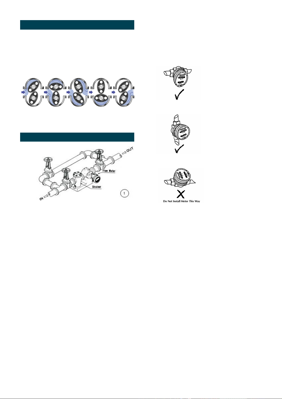
When fluid passes through the meter the rotors
turn, as shown in the diagram below.
One of the rotors is fitted with a gearing pinion which
(through a secondary gearing set) transfers the
rotation of the rotor to the Mechanical Register.
INSTALLATION PROCEDURE
6. The meter can be installed in any orientation as
long as the meter shafts are in a horizontal plane.
(Refer to diagram below for correct installation)
The mechanical register can be removed and re
orientated to a different plane if required.
.
1. It is recommended that when setting up pipe work
for meter installations, a bypass line be included
in the design. This provides the facility for a meter
to be removed for maintenance without interrupt
ing production. (see figure above)
2. Use thread sealant on all pipe threads.
3. For pump applications ensure pipe work and
Meter have the appropriate working pressure
rating to match the pressure output of the pump.
Refer to Meter Specifications section for further
details.
direction.
4 Install a wire mesh strainer, as close as possible
to the inlet side of the meter.
Meter 1/2”- 2” 250 micron / 60 mesh
5 Ensure that the meter is installed so that the
flow of the liquid is in the direction of the arrows
embossed on the meter body.
Note: Incorrect installation can cause premature
wear of meter components.
7. Do not over tighten meter connections. .
8. It is important that after initial installation you
fill the line slowly, high speed air purge could
cause damage to the rotors.
9. Test the system for leaks.
10. Check the strainer for swarf or foreign material,
after the first 200 litres check periodically,
particularly if the flow rate is noted to be
decreasing.
5
Page 6
Maintenance Procedures
Disassembly - Flow Meter
Ensure that the fluid supply to the meter is
disconnected, and the line pressure is released
before disassembly.
Refer to the exploded parts diagram and parts list.
1) Remove the four screws located on the face of the
register. Then remove the face plate cover
including register assembly.
2) Remove the four register mounting screws and
remove the lower half of the register housing.
3) Remove the six cover plate screws and remove
the cover plate.
4) Remove the six meter cap screws and remove the
meter cap.
5) Remove rotors.
Reassembly - Flow Meter
1) Before reassembling check the condition of
the rotors (replace if necessary).
Note: there is one long and one short shaft. The
short shaft is to accommodate the rotor with the
gearing pinion fitted
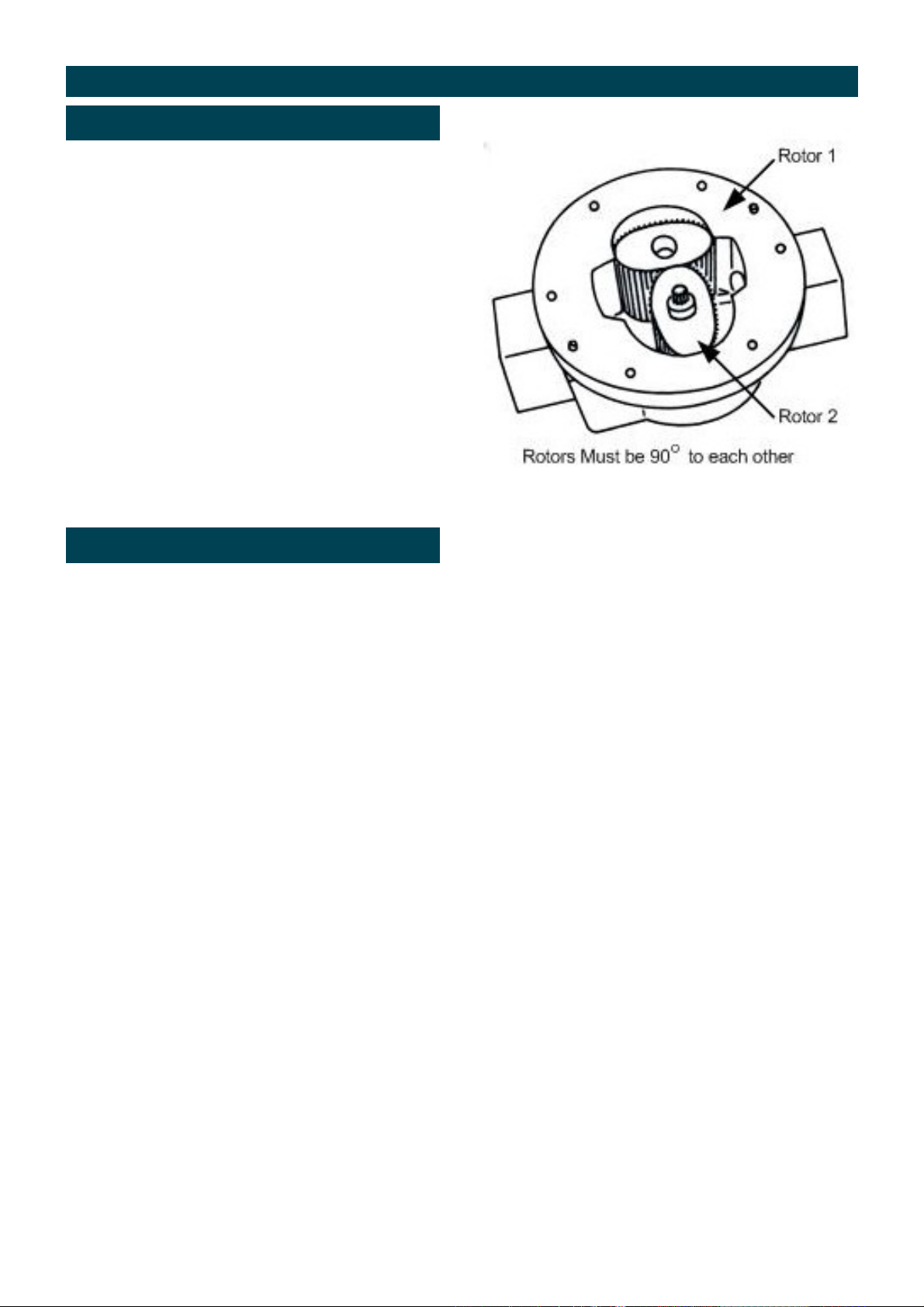
2) Replace the rotors onto the shafts at 90 degrees
to each other and check their operation by turning
either of the rotors.
If the rotors are not in mesh correctly or do
not move freely, remove one of the rotors
and replace correctly at 90 degrees to the other
rotor.
3) Re-check the operation of the rotors
4) Inspect the gears in the meter cap for wear.
(Replace if required, refer to exploded diagram)
5) Replace the o’ring into groove in the meter cap, if
the o’ring has grown or is damaged in any way
replace it with a new part.
6) Replace the meter cap making sure that the gear
on the rotor is meshing correctly with the gear in
the meter cap. Insert the cap head screws and
tighten in a diagonal sequence 1, 4, 2, 5, 3, 6.
7) Replace the cover plate inspect the o-ring, bevel
gear, for wear or damage. (Replace if necessary).
6
Page 7
Flowmeter Specifications
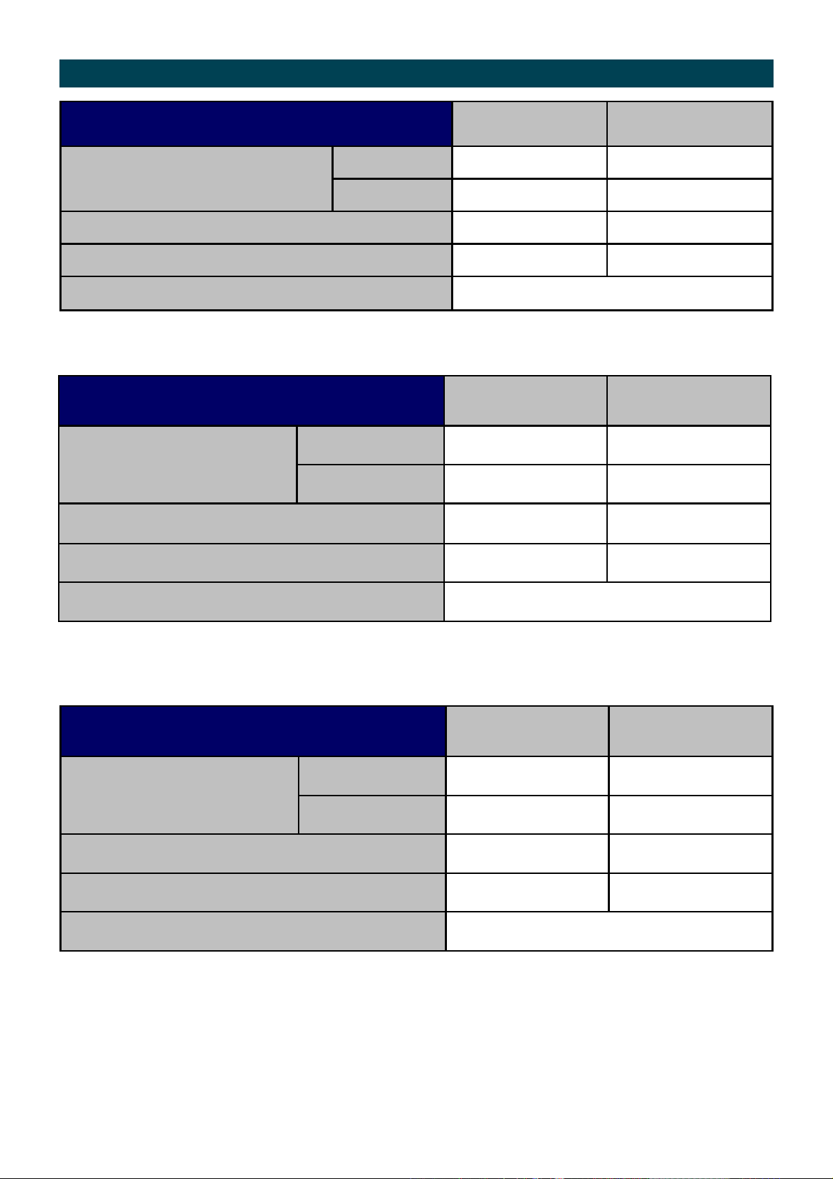
SERIES FPDM3004, FPDM3204
Metric US
Below 5 cP 3 to 25 L/min 0.8 to 6.6 G/min
Flow Range
5 to 1000 cP 2 to 30 L/min 0.5 to 8 G/min
Maximum Operating Temperature -40 - 80°C -40 - 176°F
Maximum Operating Pressure1 3400 kPa 500 PSI
Accuracy of Reading ±1%
1. Conforms to Directive 97/23/EC—Cat 1
SERIES FPDM3005, FPDM3205, FPDM3305
Metric US
Below 5 cP 10 to 100 L/min 2.6 to 26 G/min
Flow Range
5 to 1000 cP 6 to 120 L/min 1.6 to 32 G/min
Maximum Operating Temp (Standard / High Temp Version) 80°C / 120°C 176°F / 248°F
Maximum Operating Pressure 1 3400 kPa
500 psi
Accuracy of Reading ±1%
1. Conforms to Directive 97/23/EC—Cat 1
SERIES FPDM3006, FPDM3206, FPDM3306
Metric US
Below 5 cP 15 to 235 L/min 4 to 62 G/min
Flow Range
5 to 1000 cP 10 to 250 L/min 2.6 to 66 G/min
Maximum Operating Temp (Standard / High Temp Version) 80°C / 120°C 176°F / 248°F
Maximum Operating Pressure
1
3400 kPa
500 psi
Accuracy of Reading ±1%
1. Conforms to Directive 97/23/EC—Cat 1
7
Page 8
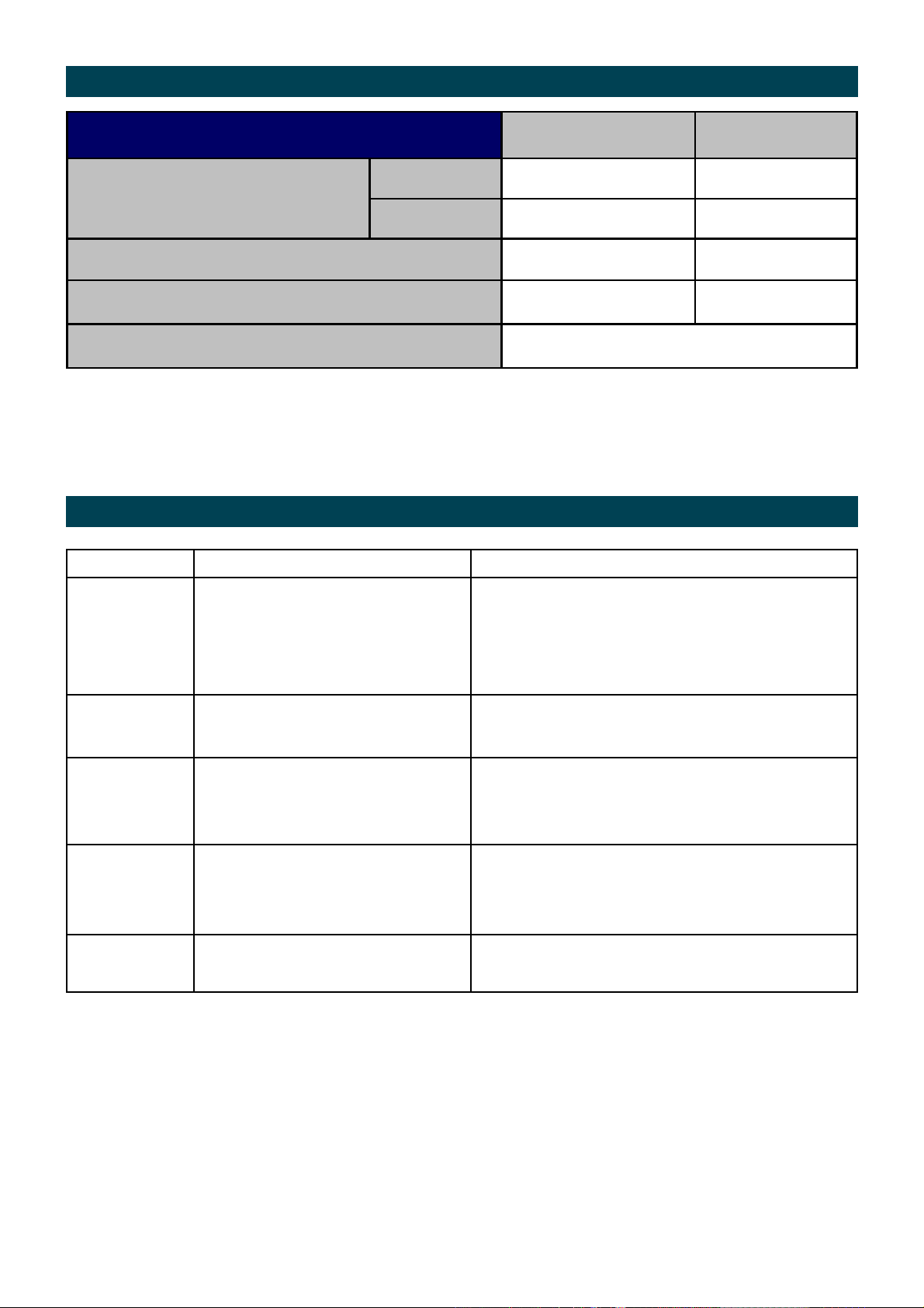
Flowmeter Specifications
SERIES
FPDM3007, FPDM3207, FPDM3307
Metric US
Below 5 cP 15 to 500 L/min 4 to 130 G/min
Flow range
5 to 1000 cP 15 to 500 L/min 4 to 130 G/min
Maximum Operating Temperature (Standard / High Temp) 80°C / 120°C 176°F / 248°F
Maximum Operating Pressure1 3400 kPa
500 psi
Accuracy of Reading ±1%
1. Conforms to Directive 97/23/EC—Cat 1
Troubleshooting Guide
Problem Cause Remedy
Fluid will not flow
through meter
Reduced flow
through meter
Meter reading
inaccurate
Fluid flows but no
reading on meter
Fluid leaks into
register
a) Foreign matter blocking rotors
b) Line strainer blocked
c) Damaged rotors
d) Meter connections over tightened
e) Fluid is too viscous
a) Strainer is partially blocked
b) Fluid is too viscous
a) Fluid flow rate is too high or too low
b) Air in fluid
c) Excess wear caused by incorrect installation
a) Bevel gear is loose on shaft
b) Rotor drive gear is damaged
c) Transmission gears damaged
d) Register gears damaged
a) Seal worn or damaged on the cover
plate
a) Dismantle meter, clean rotors (strainer must be fitted in
line)
b) Clean strainer
c) Replace rotors (Strainer must be fitted in line)
d) Re-adjust connections
e) See specifications for maximum viscosity
a) Clean strainer
b) See specifications for maximum viscosity
a) See specifications for minimum and maximum flow rates
b) Bleed air from system
c) Check meter body and rotors. Replace as required. Refer
to installation instructions
a) Tighten grub screws
b) Replace rotor
c) Replace gears
d) Replace register assembly
a) Replace seal (Check seal compatibility with fluid)
8
Page 9
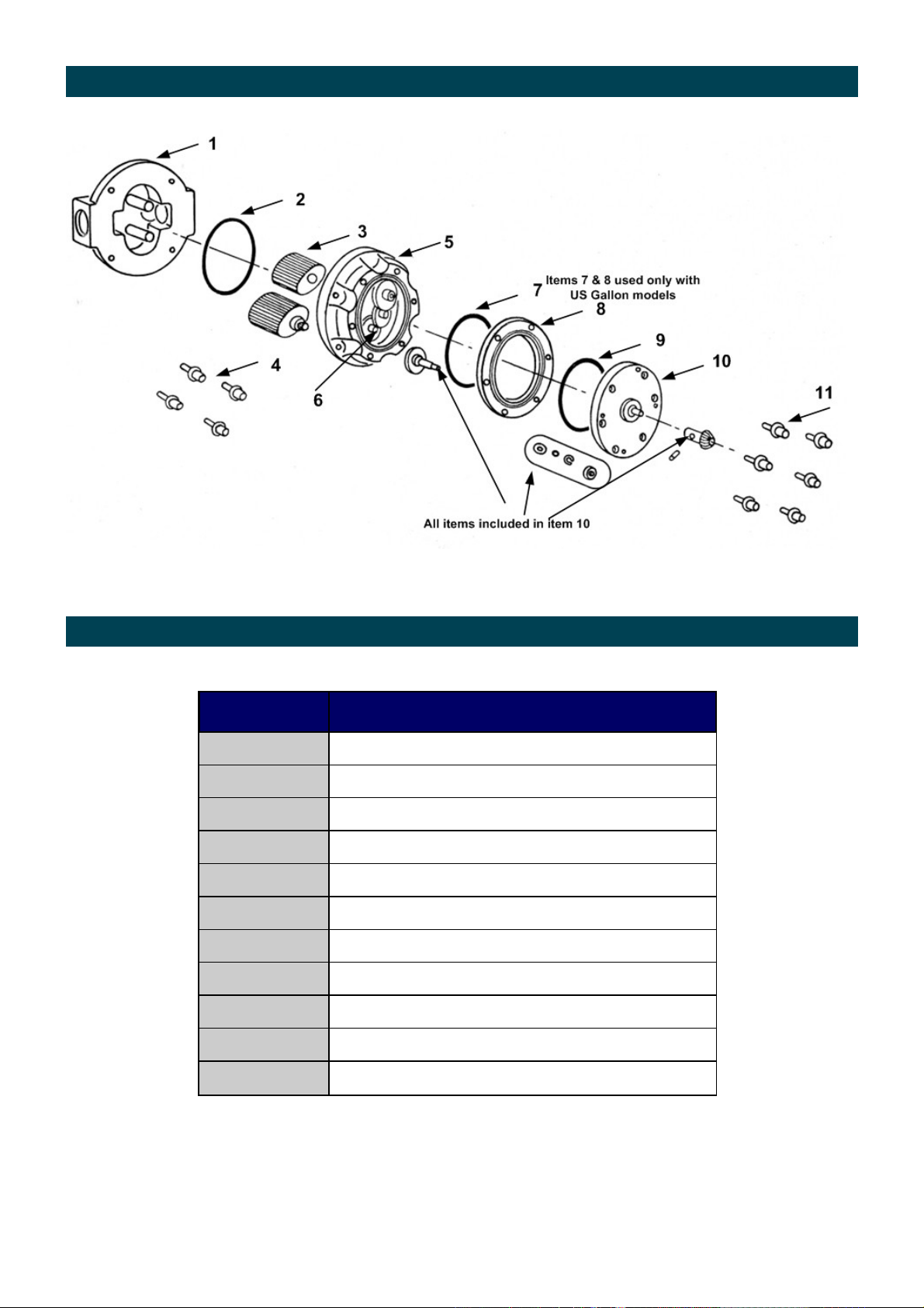
Series FPDM3x04 Exploded diagram
Series FPDM3x04 Parts Listing
Item No. Part Description
1
2
3
4
5
6
7
8
9
10
11
Meter Body
Meter Cap 0-Ring
Rotors Set
Meter Cap Bolts
Meter Cap
Gear Set
Spacer Ring O-Ring (US gallon models only)
Spacer Ring (US gallon models only)
Cover Plate O-Ring
Cover Plate Seal and Bush set
Cover Plate Screws
9
Page 10
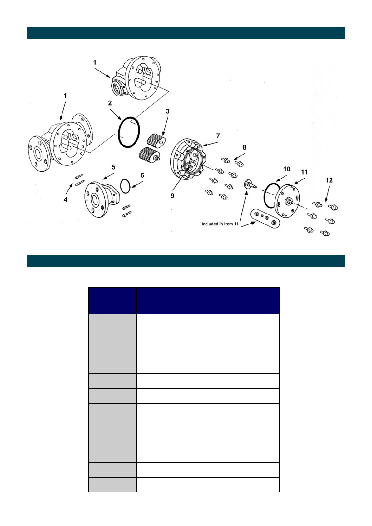
Series FPDM3x05 - FPDM3x07 Exploded Diagram
Series FPDM3x05 - FPDM3x07 Parts Identification
Item No. Part Description
1
2
3
4
5
6
7
8
9
Meter Body
Meter Cap 0-Ring
Rotors Set
Flange Bolts
Flange Adaptor
Flange O-Ring Set
Meter Cap
Meter Cap Screws
Gear Set
10
11
12
O-Ring - Cover Plate
Cover Plate and Gear Set
Cover Plate Screws
10
Page 11
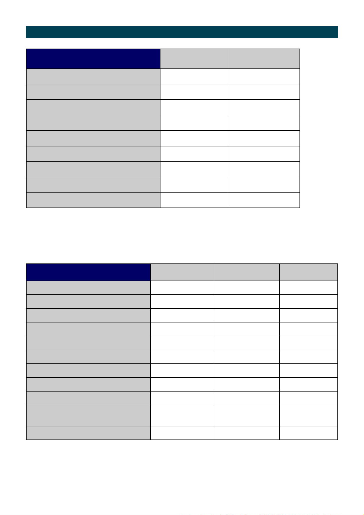
Wetted Parts
SERIES FPDM3x04 FPDM3004 FPDM3204
Meter Body
Rotor Shaft
Rotors - Standard
Rotor Bushes
Meter Cap
Gear Assembly
Cover Plate
Output Gear and Shaft assy.
O Rings
Al SS
SS SS
PPS PPS
- CA
Al SS
SS/POM SS/POM
SS SS
SS/FFKM/POM SS/FFKM/POM
FKM K
SERIES FPDM3x05 FPDM3005 FPDM3305 FPDM3205
Meter Body
Rotor Shafts
Rotors - Standard
- High Temp.
- High Viscosity.
Rotor Bushes
Meter Cap
Gear Assembly
Cover Plate
Output Gear and Shaft assy.
O Rings
Al Al SS
SS SS SS
PPS SS PPS
- - SS
- SS SS
- CA CA
Al Al SS
SS/POM SS/POM SS/POM
SS SS SS
SS/FFKM/POM SS/FFKM/POM SS/FFKM/POM
FKM K K
11
Page 12
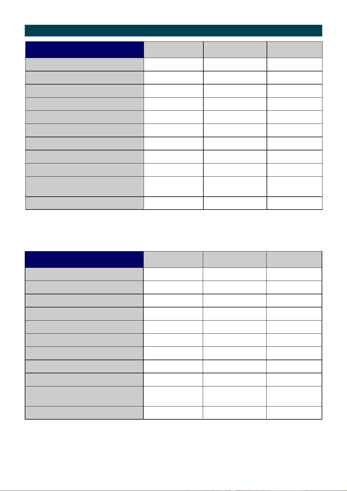
Wetted Parts
SERIES FPDM3x06 FPDM3006 FPDM3306 FPDM3206
Meter Body
Rotor Shafts
Rotors - Standard
- High Temp.
- High Viscosity.
Rotor Bushes
Meter Cap
Gear Assembly
Cover Plate
Output Gear and Shaft assy.
O Rings
Al Al SS
SS SS SS
PPS Al PPS
- - SS
- SS SS
- CA CA
Al Al SS
SS/POM SS/POM SS/POM
SS SS SS
SS/FFKM/POM SS/FFKM/POM SS/FFKM/POM
FKM K K
SERIES FPDM3x07 FPDM3007 FPDM3307 FPDM3207
Meter Body
Rotor Shafts
Rotors - Standard
- High Temp.
- High Viscosity.
Rotor Bushes
Meter Cap
Gear Assembly
Cover Plate
Output Gear and Shaft assy.
O Rings
Al Al SS
SS SS SS
PPS Al PPS
- - SS
- SS SS
- CA CA
Al Al SS
SS/POM SS/POM SS/POM
SS SS SS
SS/FFKM/POM SS/FFKM/POM SS/FFKM/POM
FKM K K
12
Page 13

Wetted Parts
K - FEP/PTFE Encapsulated
SS - Stainless Steel 316
Al - Aluminium AA610
CA - Carbon
FKM - Fluoroelastomer
PPS - Polyphenylene Sulphide
PVDF - Polyvinylidene Flouride
POM - Acetal
PTFE - Polytetrafluoroethylene
FFKM - Perfluoro Elastomer
13
Page 14
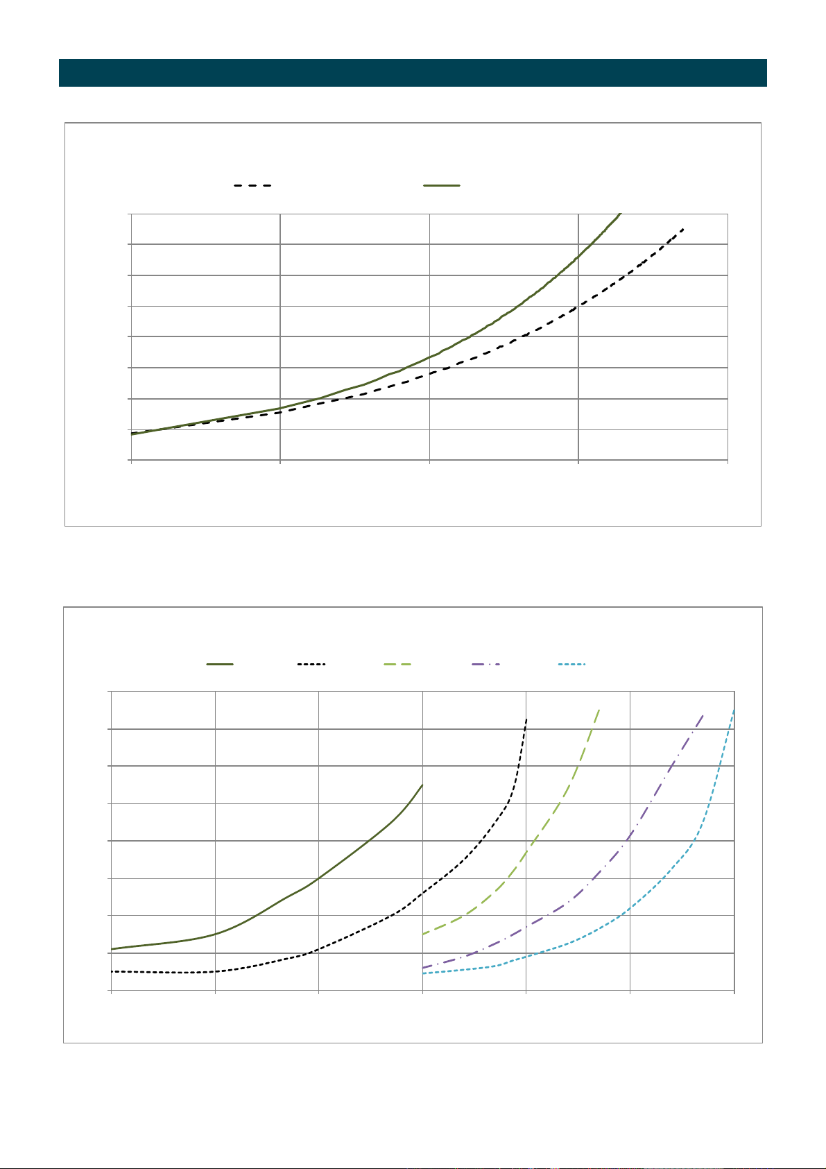
PRESSURE DROP v VISCOSITY
0
2
4
6
8
10
12
14
16
1 10 100 1000 10000
PRESSURE (psi)
VISCOSITY (cps)
STANDARD ROTORS
Std Rotors - 50% Flow Std Rotors - 100% Flow
0
2
4
6
8
10
12
14
16
1 10 100 1,000 10,000 100,000 1,000,000
PRESSURE (psi)
VISCOSITY (cps)
HIGH VISCOSITY ROTORS
100% Flow 50% Flow 25% Flow 10% Flow 5% Flo w
100% 50%
100%
50%
25%
10%
5%
14
Page 15
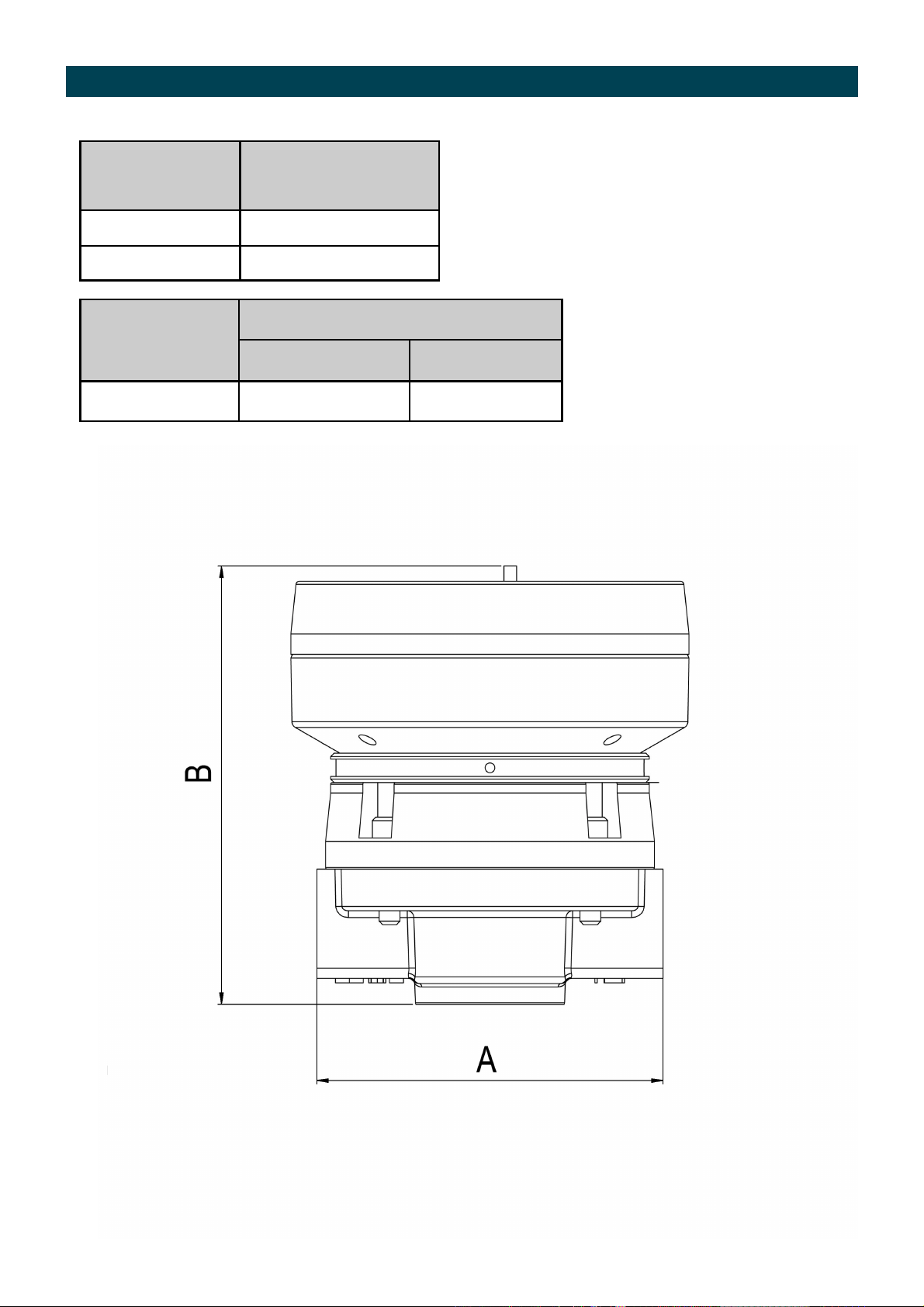
Dimensions series 3x04
Register Type B – Register Height
M (Ltr) 123mm
M (USG) 128mm
A – Face to Face length
FPDM3004 FPDM3204
NPT
100mm 100mm
Type M mechanical register
15
Page 16
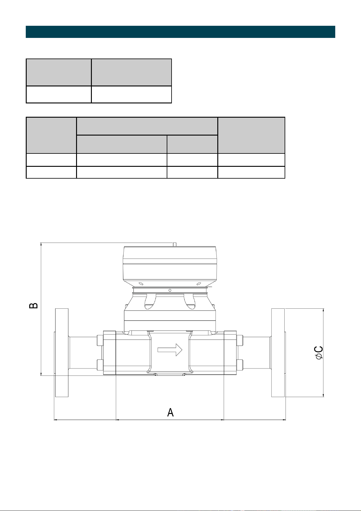
Dimensions series 3x05
Register Type B – Register Height
M 159mm
NPT
ANSI
A – Face to Face
FPDM3005 / FPDM3305 FPDM3205
133mm 143mm
284mm 294mm 108mm
C – Flange
Diameter
Type M mechanical register
16
Page 17
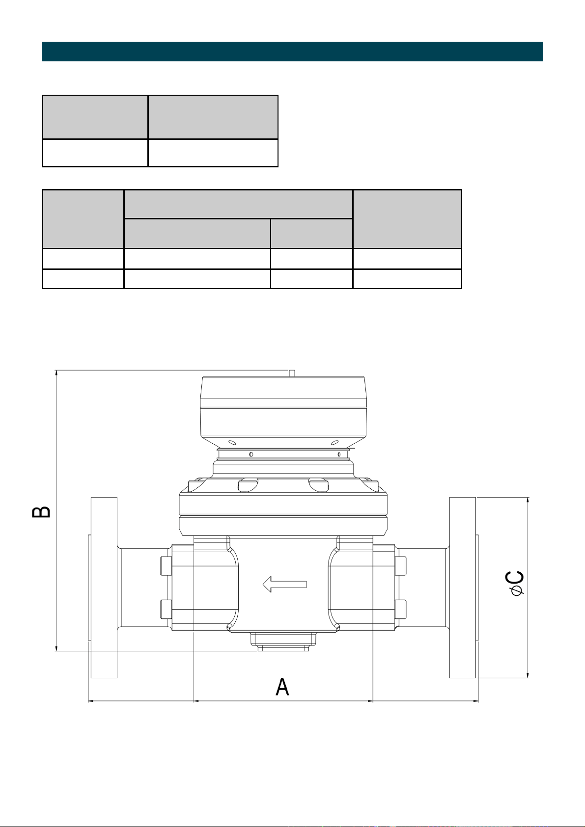
Dimensions series 3x06
Register Type B – Register Height
M 191mm
NPT
ANSI
A – Face to Face
FPDM3006 / FPDM3306 FPDM3206
124mm 124mm
270mm 270mm 127mm
C – Flange
Diameter
Type M mechanical register
17
Page 18
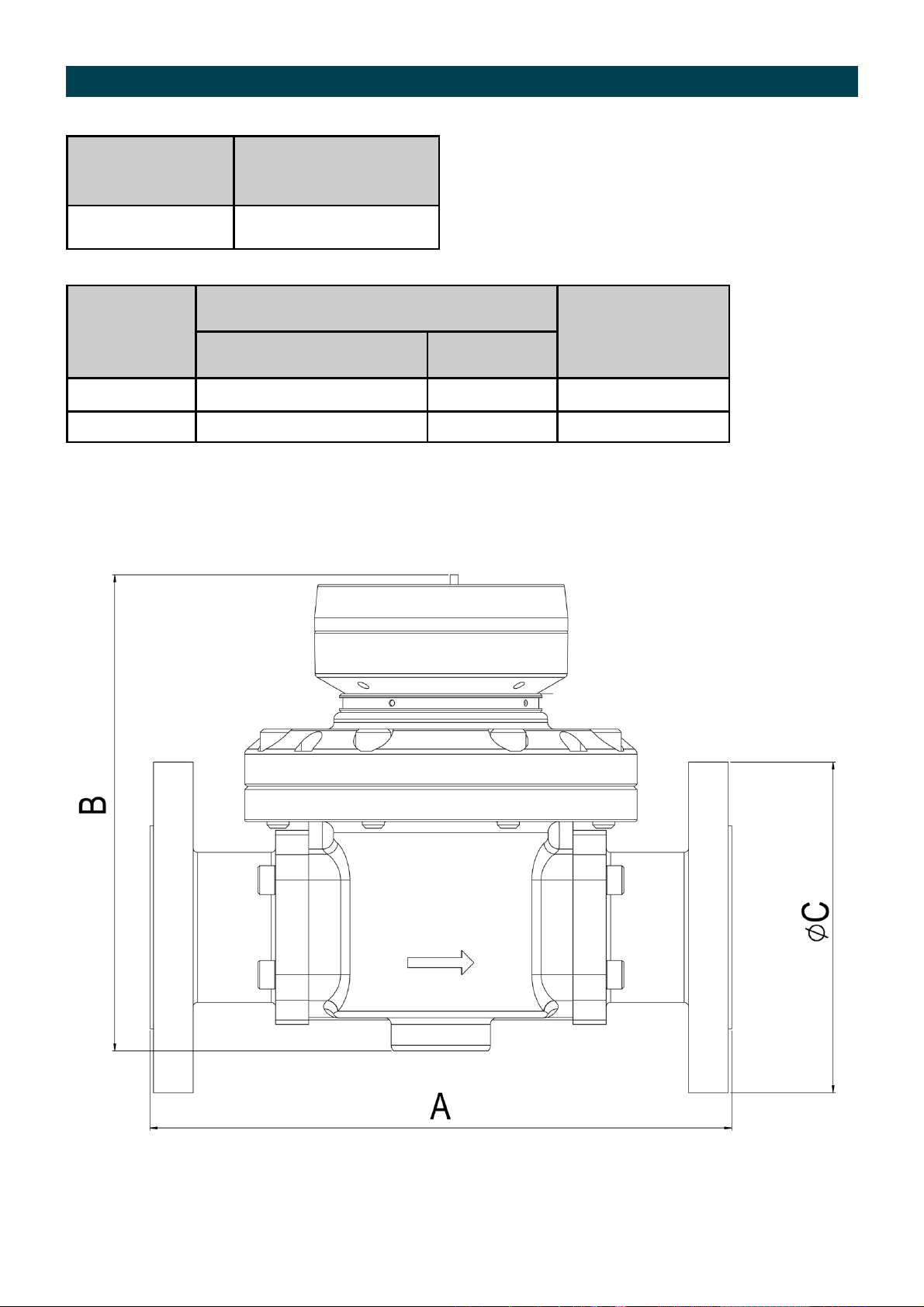
Dimensions series 3x07
Register Type B – Register Height
M 210mm
NPT
ANSI
A – Face to Face
FPDM3007 / FPDM3307 FPDM3207
210mm 210mm
264mm 264mm 152mm
C – Flange
Diameter
Type M mechanical register
18
Page 19

WARRANTY/DISCLAIMER
OMEGA ENGINEERING, INC. warrants this unit to be free of defects in materials and workmanship for a
period of 13 months from date of purchase. OMEGA’s WARRANTY adds an additional one (1) month
grace period to the normal one (1) year product warranty to cover handling and shipping time. This
ensures that OMEGA’s customers receive maximum coverage on each product.
If the unit malfunctions, it must be returned to the factory for evaluation. OMEGA’s Customer Service
Department will issue an Authorized Return (AR) number immediately upon phone or written request.
Upon examination by OMEGA, if the unit is found to be defective, it will be repaired or replaced at no
charge. OMEGA’s WARRANTY does not apply to defects resulting from any action of the purchaser,
including but not limited to mishandling, improper interfacing, operation outside of design limits,
improper repair, or unauthorized modification. This WARRANTY is VOID if the unit shows evidence of
having been tampered with or shows evidence of having been damaged as a result of excessive corrosion;
or current, heat, moisture or vibration; improper specification; misapplication; misuse or other operating
conditions outside of OMEGA’s control. Components in which wear is not warranted, include but are not
limited to contact points, fuses, and triacs.
OMEGA is pleased to offer suggestions on the use of its various products. However,
OMEGA neither assumes responsibility for any omissions or errors nor assumes liability for
any damages that result from the use of its products in accordance with information provided
by OMEGA, either verbal or written. OMEGA warrants only that the parts manufactured by the
company will be as specified and free of defects. OMEGA MAKES NO OTHER WARRANTIES OR
REPRESENTATIONS OF ANY KIND WHATSOEVER, EXPRESSED OR IMPLIED, EXCEPT THAT OF
TITLE, AND ALL IMPLIED WARRANTIES INCLUDING ANY WARRANTY OF MERCHANTABILITY
AND FITNESS FOR A PARTICULAR PURPOSE ARE HEREBY DISCLAIMED. LIMITATION OF
LIABILITY: The remedies of purchaser set forth herein are exclusive, and the total liability of
OMEGA with respect to this order, whether based on contract, warranty, negligence,
indemnification, strict liability or otherwise, shall not exceed the purchase price of the
component upon which liability is based. In no event shall OMEGA be liable for
consequential, incidental or special damages.
CONDITIONS: Equipment sold by OMEGA is not intended to be used, nor shall it be used: (1) as a “Basic
Component” under 10 CFR 21 (NRC), used in or with any nuclear installation or activity; or (2) in medical
applications or used on humans. Should any Product(s) be used in or with any nuclear installation or
activity, medical application, used on humans, or misused in any way, OMEGA assumes no responsibility
as set forth in our basic WARRANTY/DISCLAIMER language, and, additionally, purchaser will indemnify
OMEGA and hold OMEGA harmless from any liability or damage whatsoever arising out of the use of the
Product(s) in such a manner.
RETURN REQUESTS/INQUIRIES
Direct all warranty and repair requests/inquiries to the OMEGA Customer Service Department.
BEFORE RETURNING ANY PRODUCT(S) TO OMEGA, PURCHASER MUST OBTAIN AN AUTHORIZED
RETURN (AR) NUMBER FROM OMEGA’S CUSTOMER SERVICE DEPARTMENT (IN ORDER TO AVOID
PROCESSING DELAYS). The assigned AR number should then be marked on the outside of the return
package and on any correspondence.
The purchaser is responsible for shipping charges, freight, insurance and proper packaging to prevent
breakage in transit.
FOR WARRANTY RETURNS, please have the
following information available BEFORE
contacting OMEGA:
1. Purchase Order number under which the product
was PURCHASED,
2. Model and serial number of the product under
warranty, and
3. Repair instructions and/or specific problems
relative to the product.
OMEGA’s policy is to make running changes, not model changes, whenever an improvement is possible. This affords
our customers the latest in technology and engineering.
OMEGA is a registered trademark of OMEGA ENGINEERING, INC.
© Copyright 2013 OMEGA ENGINEERING, INC. All rights reserved. This document may not be copied, photocopied,
reproduced, translated, or reduced to any electronic medium or machine-readable form, in whole or in part, without the
prior written consent of OMEGA ENGINEERING, INC.
FOR NON-WARRANTY REPAIRS,
for current repair charges. Have the following
information available BEFORE contacting OMEGA:
1. Purchase Order number to cover the COST
of the repair,
2. Model and serial number of the product, and
3. Repair instructions and/or specific problems
relative to the product.
consult OMEGA
Page 20

Where Do I Find Everything I Need for
Process Measurement and Control?
OMEGA…Of Course!
Shop online at omega.com
TEMPERATURE
MU
Thermocouple, RTD & Thermistor Probes, Connectors, Panels & Assemblies
MU
Wire: Thermocouple, RTD & Thermistor
MU
Calibrators & Ice Point References
MU
Recorders, Controllers & Process Monitors
MU
Infrared Pyrometers
PRESSURE, STRAIN AND FORCE
MU
Transducers & Strain Gages
MU
Load Cells & Pressure Gages
MU
Displacement Transducers
MU
Instrumentation & Accessories
FLOW/LEVEL
MU
Rotameters, Gas Mass Flowmeters & Flow Computers
MU
Air Velocity Indicators
MU
Turbine/Paddlewheel Systems
MU
Totalizers & Batch Controllers
SM
pH/CONDUCTIVITY
MU
pH Electrodes, Testers & Accessories
MU
Benchtop/Laboratory Meters
MU
Controllers, Calibrators, Simulators & Pumps
MU
Industrial pH & Conductivity Equipment
DATA ACQUISITION
MU
Data Acquisition & Engineering Software
MU
Communications-Based Acquisition Systems
MU
Plug-in Cards for Apple, IBM & Compatibles
MU
Data Logging Systems
MU
Recorders, Printers & Plotters
HEATERS
MU
Heating Cable
MU
Cartridge & Strip Heaters
MU
Immersion & Band Heaters
MU
Flexible Heaters
MU
Laboratory Heaters
ENVIRONMENTAL
MONITORING AND CONTROL
MU
Metering & Control Instrumentation
MU
Refractometers
MU
Pumps & Tubing
MU
Air, Soil & Water Monitors
MU
Industrial Water & Wastewater Treatment
MU
pH, Conductivity & Dissolved Oxygen Instruments
M-5424/0714
 Loading...