

Page 1
TM
User’s Guide
Shop online at
omega.com
e-mail: [email protected]
For latest product manuals:
https://www.omega.com/
en-us/pdf-manuals
SM
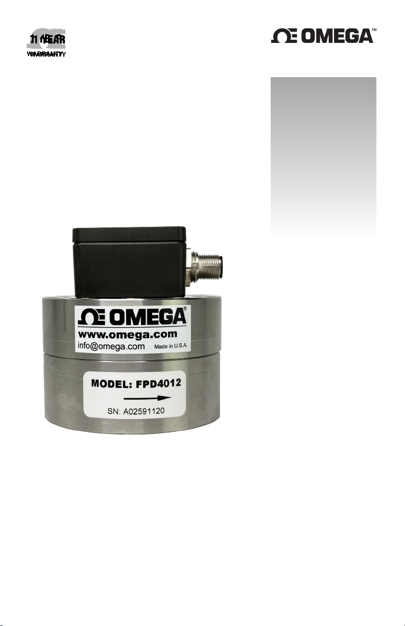
FPD-4000 SERIES
Positive Displacement Flow Meters
Page 2

omega.com [email protected]
Servicing North America:
U.S.A. Omega Engineering, Inc.
Headquarters: 800 Connecticut Ave. Suite 5N01, Norwalk, CT 06854
Toll-Free: 1-800-826-6342 (USA & Canada only)
Customer Service: 1-800-622-2378 (USA & Canada only)
Engineering Service: 1-800-872-9436 (USA & Canada only)
Tel: (203) 359-1660 Fax: (203) 359-7700
e-mail: [email protected]
For Other Locations Visit omega.com/worldwide
The information contained in this document is believed to be correct, but OMEGA accepts no liability for any errors it contains, and reserves the
right to alter specifications without notice.
Page 3

Table of Contents
Safety Denitions and Information ................................................................ 4
Unpacking .............................................................................................................. 4
Quick Start ............................................................................................................ 4
Install Pickup Sensor ........................................................................................ 4
Flush Piping ....................................................................................................... 4
Filtration ............................................................................................................. 4
Location ............................................................................................................. 4
Orientation ........................................................................................................ 5
Flow Direction ................................................................................................... 5
Description and Principle of Operation ......................................................... 6
Positive Displacement Flow Meter ................................................................. 6
All-in-One Pickup Sensor ................................................................................. 6
Installation ............................................................................................................ 7
Preferred Flow Direction .................................................................................. 7
Preferred Orientation....................................................................................... 7
Location ............................................................................................................. 7
Filtration ............................................................................................................. 7
Installing a Bypass ............................................................................................ 8
Pickup Sensor Installation ............................................................................... 8
Pickup Sensor Location .................................................................................... 8
Operation .............................................................................................................. 9
Overview ............................................................................................................ 9
Running the Flow meter .................................................................................. 9
Ramp Up ............................................................................................................ 9
Regular Cleaning ............................................................................................... 9
End of Shift and Overnight Preparations ....................................................... 10
Breakdown ........................................................................................................ 10
Plugging ............................................................................................................. 10
Filtration ............................................................................................................. 10
Maintenance ......................................................................................................... 11
Use the Maintenance Guides .......................................................................... 11
Flow Testing ....................................................................................................... 11
Plugging and Filtration ..................................................................................... 11
Calibration ......................................................................................................... 11
Storage ............................................................................................................... 12
Flow Meter Do’s and Don’ts ............................................................................... 12
Calibrations ........................................................................................................... 13
If ow readings are too high ........................................................................... 13
If ow readings are too low ............................................................................. 13
If it is necessary to adjust the existing k-factor ............................................. 13
If it is necessary to re-calculate a new k-factor ............................................. 14
Trouble-Shooting Guide ..................................................................................... 14
All-In-One Sensor ................................................................................................. 15
Technical Specications ................................................................................... 15
Materials of Construction ................................................................................ 15
Dimensional Drawing ....................................................................................... 15
Industry Standard M12-A Connectors ............................................................ 16
Signal Outputs ................................................................................................... 16
Input Source ...................................................................................................... 17
Test Mode .......................................................................................................... 17
Bluetooth Application ........................................................................................ 18
Sensor App Overview ....................................................................................... 18
Getting Started .................................................................................................. 18
Menu Navigation............................................................................................... 19
System Settings ................................................................................................. 19
Output Settings ................................................................................................. 20
3
Page 4

Safety Denitions and Information
Do not attempt to install or use your AW Gear Meters product until you have read
the safety instructions in this section. Save this manual and keep it in an easily
accessible place.
Unpacking
Separate the flow meter from packaging materials and check for any visual signs of
damage. If you determine there has been damage caused by shipping, file a claim
with the shipping company. If the flow meter appears to have been improperly
assembled or does not operate properly, return the product for replacement or
repair (see Limited Warranty information at the end of this manual).
Quick Start
To set up, install and operate your flow meter quickly, follow these step-by-step
instructions. Detailed installation, operational, and maintenance instructions begin
on page 5 in this manual. More information is also available in the Maintenance
Guide appropriate for your flow meter.
Install Pickup Sensor
Before attaching the sensor to the flow meter, check for any potential clearance
issues. It may be easier to install the sensor after you have installed the flow
meter in the line.
CAUTION: Whether the sensor requires tool or hand installation, tighten with
hand-tighten torque only.
NOTICE: Some ow meters are shipped with the sensor already installed.
Flush Piping
If feasible, flush piping to remove dirt and debris before installing flow meter.
Filtration
Filtration is recommended to prevent contaminants from entering the flow meter.
See flow meter Data Sheet for specific filter, including mesh weight and size.
Location
It’s best to install the flow meter upstream from control valves and fluid regulators,
if possible. See Figure 1.
4
Page 5
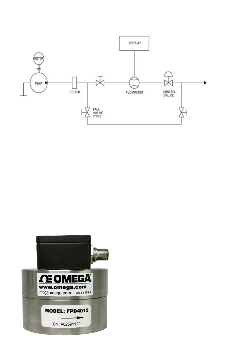
Figure 1: Typical flow meter installation with bypass
Orientation
Positive displacement gear flow meters can be installed either a horizontal or
vertical (flow up) orientation. 2-3 psi of backpressure is required to assure
the meter is always full of fluid. No straight run pipe is required upstream or
downstream of the meter.
Flow Direction
Flow direction is marked with an arrow on the flow meter. See Figure 2.
Figure 2: Flow direction
indication on label
5
Page 6

Description and Principle of Operation
Positive Displacement Flow Meter
OMEGA positive displacement flow meters are similar in design to the gear
pump. However, the principle of operation is reversed: instead of the gears
driving the medium, the medium drives the gears. A non-intrusive sensor
detects the movement of the gear. As each tooth passes the sensor, the sensor
produces a square-wave pulse and measures a discrete volume of liquid. The
resulting pulse train is proportional to the actual flow rate, providing a highly
accurate representation of the fluid flow. All flow meters are designed with
highly wear-resistant moving parts to provide exceptionally long service life. The
materials of construction are:
• stainless steel or high-strength aluminum housing
• stainless steel gears
• either tungsten carbide sleeve bushings or stainless steel ball bearings
(depending on model)
The fluids you are metering should be compatible with these materials.
All-in-One Pickup Sensor
The FPD-4000 Series comes with an all-in-one sensor that easily mounts on
the flow meter and has 3 different output types available. We have equipped
the sensor with a Bluetooth feature, which allows users to use a mobile app to
setup the sensor and view real time outputs with their smart devices. The sensor
comes equipped with an integrated linearizer for voltage and current outputs. This
sensor is RoHS-compliant and utilizes surface mount components and a more
up-to-date circuit design.
6
Page 7

Installation
Preferred Flow Direction
The preferred flow direction is marked with an arrow on the meter showing the flow
direction in which the flow meter was calibrated (see figure 2). However, the flow
meters have bi-directional flow capabilities and are often used for bi-directional
flow applications. Since the meters indicate flow in both directions, if reverse flow
detection is not desired, install a check valve up-stream of the flow meter.
Preferred Orientation
The preferred orientation for mounting gear meters, especially in low flow and
or low viscosity applications, is so that the internal shaft/gear assembly is in a
horizontal orientation (housing bolts facing sideways, not up/down). This allows
for the least amount of internal drag due to mass of gears.
Location
It is important to make sure that the flowmeter is always full of fluid and never
partially filled. Do this by making sure there is always a small amount of
backpressure on the meter, usually 2 to 5 psi minimum.
Create backpressure by making sure there is some flow restriction downstream
from the flowmeter such as a check valve, regulator, or piping rising above
location of flowmeter. See Figure 1.
Backpressure from control valving is beneficial for stable running. In similar
fashion, if a flowmeter is installed with fluid flow in a downward direction, the fluid
cannot exit the flowmeter directly into a container with no restriction due to the
fact the meter will not be full of fluid, causing inaccurate measurement.
CAUTION: Eliminate all dirt, debris and metal shavings from the piping, as
the liquid must be free from any particles larger than what the manufacturer’s
specifications allow. Install any recommended filtration before operation, as
potential plugging most often occurs at startup.
Filtration
Filtration depends on the model. Make sure to follow proper filtration requirements
for your specific model. Because the internal assembly has very small clearances,
small filter sizes are required, especially for ball-bearing flowmeter versions.
NOTE: Filters are meant to lter out impuries in the uid stream. If you are measuring uids with
llers, even if the llers are smaller than the maximum recommended lter size, please consult the
factory for correct meter selecon.
7
Page 8
Installing a Bypass
If possible, install a bypass around the flow meter, and flush existing piping with
the appropriate liquid before first use. See Figure 1.
Pickup Sensor Installation
Before attaching the sensor to the flow meter, check for any potential clearance
issues. It may be easier to install the sensor after the flow meter has been
installed in the line.
CAUTION: Do not use a wrench or Channellock®* to aid in hand installing the
pickup sensor.
CAUTION: Whether the sensor requires a tool to install or is hand installed,
tighten to hand-tighten torque only. Over tightening may cause damage to the
sensor and as a result it may not function properly.
Pickup Sensor Location
Locate the pickup and wiring away from A/C motors, actuators, heaters, relays,
etc. Use only shielded cable and if possible, a dedicated power supply for the
electronics. If sharing power with other devices in the system, be aware that
power-draw spikes from other equipment could cause a surge into the sensor,
which in turn can cause sensor to give erroneous pulses. Ensure clean power
supplies that utilize a true earth ground. Install Intrinsic Safety Barriers if the
circuit is intended to be intrinsically safe.
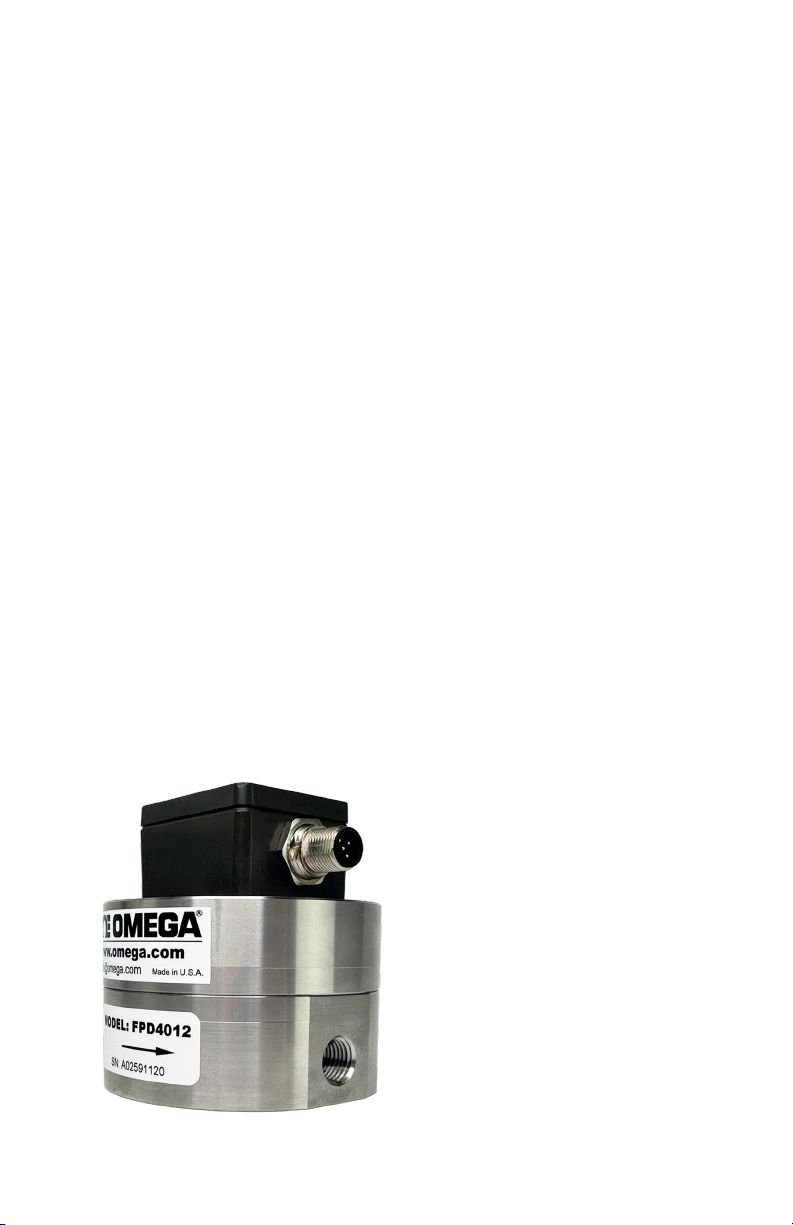
Figure 3: Flow meter with pickup sensor installed
*Channellock® is a registered trademark of Channellock, Inc.
8
Page 9

Operation
CAUTION: Before installing, operating or attempting maintenance on a flow
meter, read the appropriate Maintenance Guide. As with any precisionengineered device, always operate and maintain the equipment in
accordance with the manufacturer’s instructions.
Overview
Flow meters are designed to measure the flow of liquids, which assist in
cooling and lubrication. Always close meters to air except when air is part of
an automated purge cycle, such as certain paint systems. In this case, the air
segments are typically under 1 or 2 seconds and are interspersed with lubrication
liquid for a scrubbing effect; in addition, the air segments are short enough that
the flow meter does not dry out.
CAUTION: Do not dry lines using only pressurized air, as this will lead to
premature wear.
Running the Flow Meter
Never run the flow meter dry or spin with air only. Gear flow meters are
precision-engineered flow devices. Always maintain them in a clean, lubricated
condition with the internal parts wet at all times. Do not allow air or water to
contact the internal parts except in short (1-2 second) cycles as part of an
automated flush. If you flush meter with water, make sure to run non-corroding
fluid through the meter afterwards. Even stainless steel meters will stain or
corrode from the minerals in most water.
Ramp Up
Do not increase flow to a full flow condition instantaneously. Gear flow meters are
rugged yet precise instruments that respond almost instantaneously to changes in
fluid flow. To avoid damage to the system, increase flow to maximum over a few
seconds rather than instantaneously and do not inject high flow speeds into an
empty flow meter.
Regular Cleaning
Designing and maintaining a flush procedure that keeps the flow meter internals
clean and wet is critical to optimum performance and minimum maintenance.
Cleaning cycles vary due to the differences in coatings, equipment, and cleaning
fluids, and some testing may be prudent to determine the most efficient method.
More corrosive fluids may also require more frequency flush cycles, or if meter sits
idle for longer periods of time, such as between shifts, flushing may also be required
more often. Consult with the fluid manufacturer for recommended cleaning fluids.
9
Page 10

NOTE: During line shutdowns such as overnight and over weekends, ush and leave meters lled
with proper cleaning uid under pressure to allow any residue that may have built up to soak and
dissolve.
End of Shift and Overnight Preparations
At the end of a shift or overnight, leave cleaning fluid in the flow meter under
pressure, to soak. This helps keep unflushed residual fluids from drying, and
facilitates subsequent startups. Opening a flow meter after a flush cycle helps
determine if the purge is thoroughly cleaning the flow meter.
Breakdown
NOTE: Full breakdown instrucons are included in the Maintenance Guide.
NOTE: If you remove a ow meter from the line during maintenance, do not allow uids to dry
inside. Clean the internals immediately, lubricate them, and cap the uid ports.
NOTE: Clean the carbide surfaces at the point where the gear rotates on the sha. Buildup here
may occur as a thin smear and may be dicult to see, but causes fricon and accelerate addional
buildup later when the gears are reinstalled. Spin the gears by hand to verify that they rotate freely
on the sha and apply a suitable lubricaon uid before closing the ow meter. Aer ghtening the
bolts, a short squirt of shop air will briey spin the gears, which should be easily audible.
CAUTION: Do not overspin gears if using shop air to verify free rotation of
gears prior to installation.
CAUTION: Do not use wrenches or a Channellock to aid in re-installing the
pickup sensor by hand. Whether you are installing the sensor with a tool or by
hand, tighten to hand-tighten torque only.
Plugging
In the event of plugging, the flow meter passes a reduced volume of fluid with an
increased backpressure and no frequency output. Careful installation is important
because this is the time when contaminants such as tape or metal shavings can
enter the flow meter. Filters should be in line to prevent oversized particles from
entering the flow meter.
In the event the flow meter needs to be returned to the factory for further
evaluation, flush the flow meter in place and cap the ports. Pack carefully (with
original packing materials, if possible) prior to shipping to prevent damage.
Filtration
Filtration is recommended to prevent contaminants from entering the flow meter.
If the flow meter is plugged, a reduced flow can still be observed from the nozzle
or outlet, as fluid pressure squeezes fluid through the flow meter. Should this
occur, review the cleaning and maintenance procedures in the following sections.
10
Page 11

Maintenance
Follow these general guidelines for operating and maintaining your positive
displacement flow meter.
Use the Maintenance Guides
Always review the Maintenance Guides provided with the flow meter
(download additional copies at www.awgearmeters.com ) prior to attempting
any maintenance work. The majority of down time and repairs is the result
of breakages due to improper maintenance actions, lack of training or rough
handling.
Flow Testing
Do not use water for flow testing. The viscosity of water is too low to produce
accurate results unless the flow rate is elevated, and the internals would then
have to be dried and lubricated to avoid corrosion or scaling. If system calibration
is necessary, the preferred calibration fluid is the actual fluid to be metered.
Alternatively, using a fluid with a viscosity of approximately 30 cSt° such as
mineral oil or thinned glycerin is recommended.
Plugging and Filtration
Filtration is recommended to prevent contaminants from entering the flow meter.
Should the flow meter become plugged, a reduced flow may still be observed
from the outlet as fluid pressure will squeeze fluid through the flow meter –
visual flow does not necessarily mean that the flow meter’s gears are turning.
If contaminants are causing the plugging, install filtering. If particle buildup
repeatedly causes plugging, review the cleaning and maintenance procedures in
the Regular Cleaning section on page 8. Because of the considerable differences
in fluid types and in-plant procedures, some trial and error may be required to
determine the ideal flushing or cleaning regimen.
Calibration
A calibration factor (k-factor) is established at the factory on a preferred
calibrating fluid. This number, which is provided with the flow meter either on a
Calibration Data Sheet or on a tag attached to the flow meter, is usually accurate
for a wide variety of fluids and should not usually be changed. Should the data
sheet become lost, contact the factory for a duplicate copy. See the Calibrations
section on page 12 for a calibration verification procedure.
*cSt is a unit of kinemac viscosity that equals one hundredth of a stoke.
11
Page 12

Storage
When the flow meter is idle or stored for any extended period, perform the
following:
1. Clean the internals thoroughly with the appropriate fluid
2. Lubricate with a light oil or other non-corrosive fluid
3. Cap or plug the ports to prevent drying
Flow Meter Do’s and Don’ts
DO: Leave flushing fluid in the lines overnight or during extended off-times. This
keeps internals wet, prevents residual fluids from drying, and facilitates startups.
DO: Follow the Maintenance Guide instructions when opening and cleaning a flow
meter. During cleaning, separate the gears from the shafts. On carbide bearings,
clean inside the center of the gear bearing and on the outer surface of the shafts
at the point where the gear rotates on the shaft. Apply a suitable lubricating fluid
before closing the flow meter. After tightening the bolts, a short squirt of shop
air will briefly spin the gears, which should be easily audible.
DO: Install and maintain filters. Install the recommended filter to eliminate
potential plugging. Should plugging occur, the flow meter will still pass fluid but
with no signal output.
DO: Check electrical compatibility between the flow meter’s output signal and the
input of the PLC. If signals are not being detected at startup, first check wiring
and electrical compatibility.
DO: Verify reliable grounding of electrical parts, as per installation guidelines. A
dedicated power supply is recommended. Voltage spikes on shared power lines,
negligent grounding and sloppy wiring will likely produce erratic readings and
chronic maintenance.
DO: Install the flow meter immediately upstream of the regulator or control valve.
The control valve provides backpressure, which stabilizes the flow.
DON’T: Allow air into the flow meter. Always keep the flow meter internally wet.
DON’T: Dry lines using pressurized air. Flow meters are designed to flow liquids.
Close meters to air except when air is part of an automated purge cycle. Do not
dry lines after purging.
12
Page 13

DON’T: Allow materials to dry inside the flow meter. When a flow meter is
removed from the line during maintenance, clean the internals immediately,
lubricate the gears, and cap the fluid ports.
DON’T: Over tighten the pick-up sensor beyond hand tight. When installing the
pickup sensor, turn it in lightly to a hand-tight torque. Do not use a wrench on
the pickup as over tightening may cause a dimple of metal under the sensor nose
to protrude into the gear cavity and interfere with the gear’s rotation.
DON’T: Use water or solvent for calibration or test purposes. Water or solvent
may not turn the gears at low flow and may leave the impression that the flow
meter is not functioning. A calibration factor (kfactor) is issued with the flow
meter, which is valid for most fluids except water or equivalent viscosities.
Calibrations
Each flow meter is calibrated and given a “k-factor” using a standard calibrating
fluid at the factory. This number is accurate for all fluids with most viscosities,
except the most water-like. There should be no need to change this except for
fluid viscosities below 30cSt.
If ow readings are too high
If the display shows significantly more than the volume actually dispensed or
shows flow when there is definitely no flow, this most likely indicates an electrical
noise problem. In such cases, turn off nearby motors, heaters or relays, check
cable shielding, and establish a clean ground independent of other electrical
devices before repeating accuracy tests. If the problem continues, it may be
necessary to relocate the offending device or reroute cabling away from noise
sources.
If ow readings are too low
If the display shows significantly less than the volume actually dispensed, most
likely the flow meter has a high slippage factor, and the fluid is bypassing the
gears and the k-factor may require adjustment. Dirt or dried material can also
keep gears from rotating freely.
If it is necessary to adjust the existing k-factor
Trigger at least 500ml of your sample fluid in a steady stream at approximately
the desired flow rate into a graduated beaker. Compare the volume in the beaker
to the volume on the display. Do not time the operation; merely measure the
volume dispensed. Repeat the sample 3 times and take an average. If the
result is outside an acceptable margin, adjust the k-factor by the percentage
13
Page 14
of difference between the average beaker sample and the average displayed
total. If the error is not rectified, clean the flow meter thoroughly and repeat the
procedure. Do not use water for this test. For most accuracy results,
calibrate using fluid to be measured with flowmeter.
If it is necessary to re-calculate a new k-factor
You will first need a data-collecting instrument to count pulses produced by the
flow meter. Trigger at least 500ml of your sample fluid in a steady stream at
approximately the desired flow rate into a graduated beaker.Divide the number of
pulses by the volume dispensed and the result is your new k-factor in the units
of your sample. In the example above, the k-factor units would be impulses/ml.
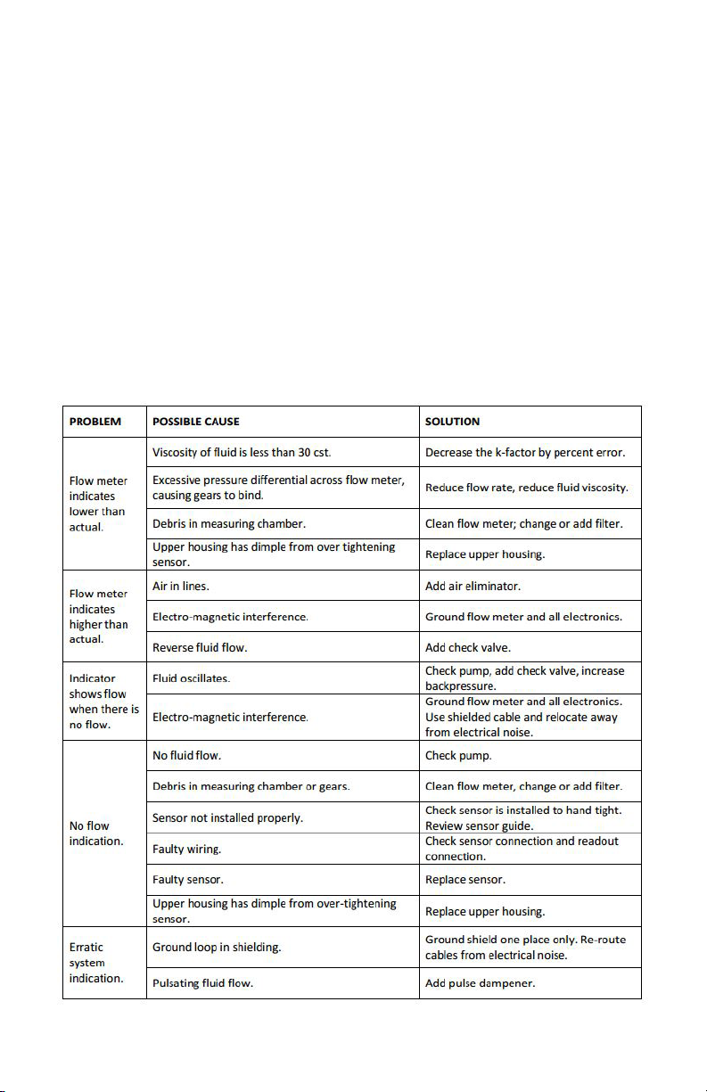
Trouble-Shooting Guide
14
Page 15
All-In-One Sensor
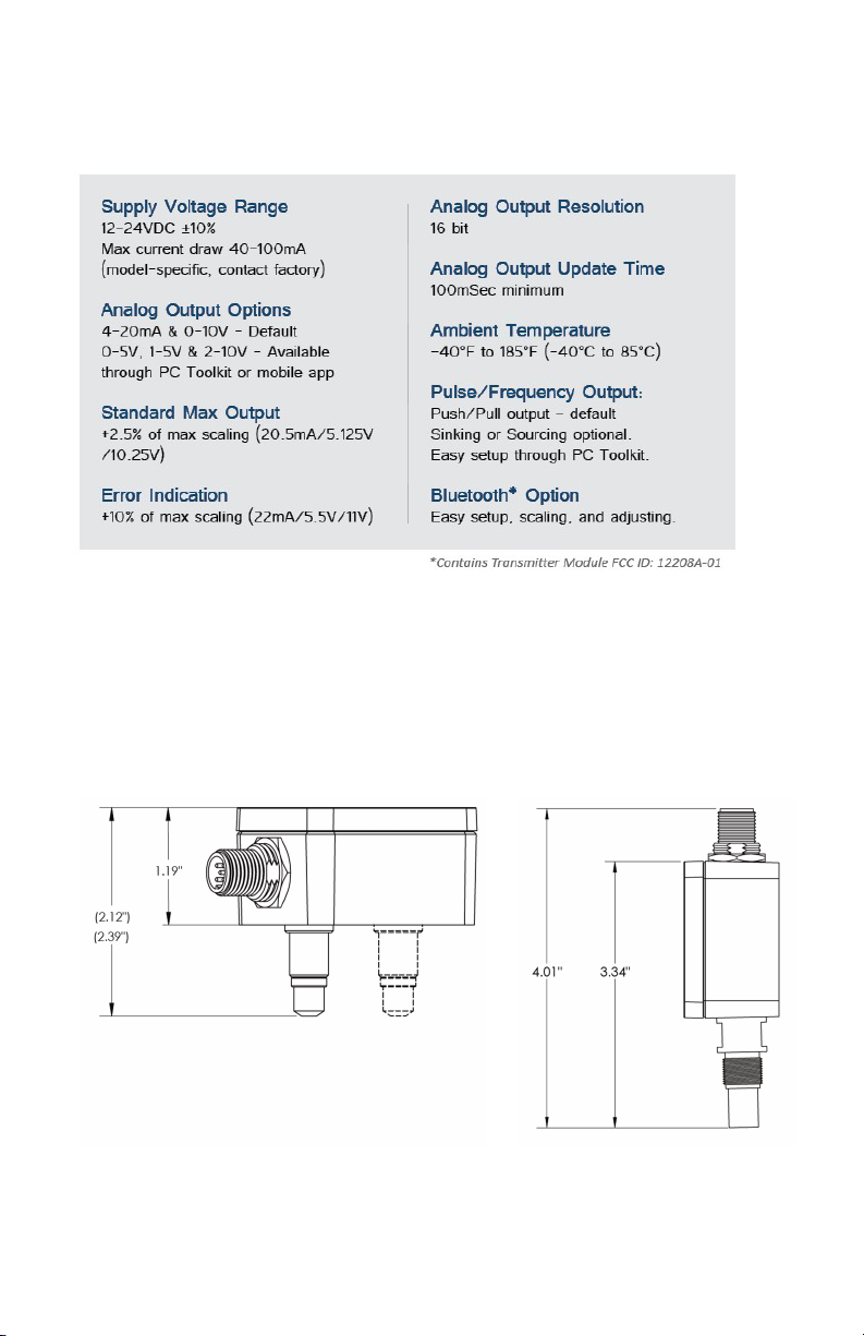
Technical Specications
Materials of Construction
• Housing: Anodized Aluminum
• Pickup: 303 Stainless Steel body with Zytel cap
• Seal: Chloroprene Rubber (CR)
Dimensional Drawing
Figure 4: Flow sensor styles: Flush mount (left) is standard;
M14 thread-in style is for high temperature applications
15
Page 16
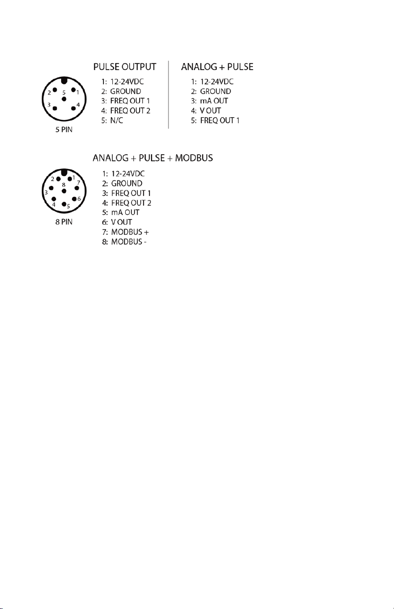
Industry Standard M12-A Connectors
Figure 5: Cable Pin-outs
Signal Outputs
Frequency
Each model of sensor comes equipped with a frequency output. Single pulse
versions need to be specified as Sinking or Sourcing when ordered. For all
others, frequency out can be set to 3 different output types; Push-Pull, Sinking,
and Sourcing. Push-pull is the default setting, and all other options can be set
using the Bluetooth app or computer toolkit.
Analog
Current Output – The sensor offers a sourced 4-20 mA output that can be
scaled via the Bluetooth app or computer toolkit. Current output is referenced to
supply ground.
Voltage Output – The sensor offers 4 types of Voltage outputs; 0-5, 1-5, 0-10,
2-10 Volts. Default output is 0-10V and can be changed via the Bluetooth app
and computer toolkit. Voltage output is referenced to supply ground
16
Page 17

Input Source
For versions with dual pick-ups, the sensor offers 5 different choices on the
frequency output lines; Signal 1, Signal 2, Signal 1+2, Direction, and Limits.
Signal 1 – Outputs frequency from pick-up 1 (leads signal 2 by 90° phase shift)
Signal 2 – Outputs frequency from pick-up 2 (trails signal 1 by 90° phase shift)
Signal 1+2 – Outputs 2x the frequency. Users using this output must multiply the
k-factor by 2
Direction – Outputs a high or low signal based on the flow direction. In forward
direction, sensor will output a high signal equal to the supply voltage. In reverse
flow direction, sensor will output a low signal.
Limits – Outputs a high or low signal based off the selected limit source, Total or
Rate.
Test Mode
The sensor comes equipped with a push button that allows the sensor to output
a set frequency on the signal output lines. There are 3 modes of operation,
indicated by the green LED on the board. (D2 for frequency boards and D4 for
analog and Modbus)
Mode 1 – Standard operating mode indicated with 1 green LED that blinks every
3 seconds
Mode 2 – Outputs 10 Hz frequency. For dual sensor versions, it outputs on both
signal outs with signal 1 leading signal 2 by a 90 degree phase shift.
Mode 3 – Outputs 50 Hz frequency. For dual sensor versions, it outputs on both
signal outs with signal 2 leading signal 1 by a 90 degree phase shift.
17
Page 18
Bluetooth Application
Sensor App Overview
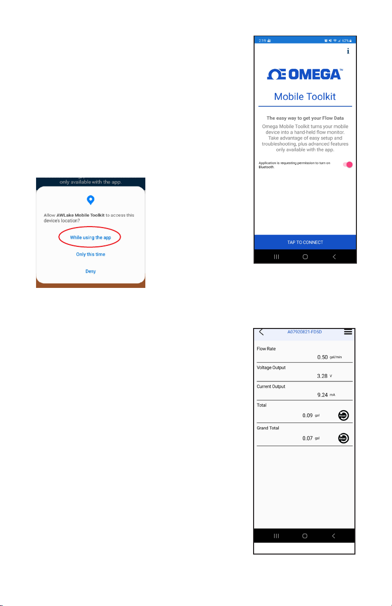
For the Modbus and Analog versions of this product
a Bluetooth app for Android devices (Android
10 or newer operating systems) is available that
allows scaling of the analog output wirelessly. The
application can be found on the OMEGA website or
on the Google Play store.
*Allow device
location for the
app, or devices
will not appear
in search list.
Figure 7: Location
Permission
Figure 6: Main Menu
Getting Started
Download and open the application. It will ask to
turn on Bluetooth, if not already on. Press the
button at the bottom to scan for devices (Figure
6). The default name of the device will be the
same as the serial number on the outside of
the device. Tap on the name to connect. Once
connected the device name will appear at the top
of the display with flow rate, Voltage output, and
Current output. (Figure 8)
Menu Navigation
Press the three lines in the top right corner to
access the setup menu (Figure 9)
System Settings: Adjust K-factor, Filter, Flow
Units, Flow Time Base, Max Flow Rate, Max Flow
Units, Max Time Base, and Bluetooth name
Figure 8: Device Menu
Page 19
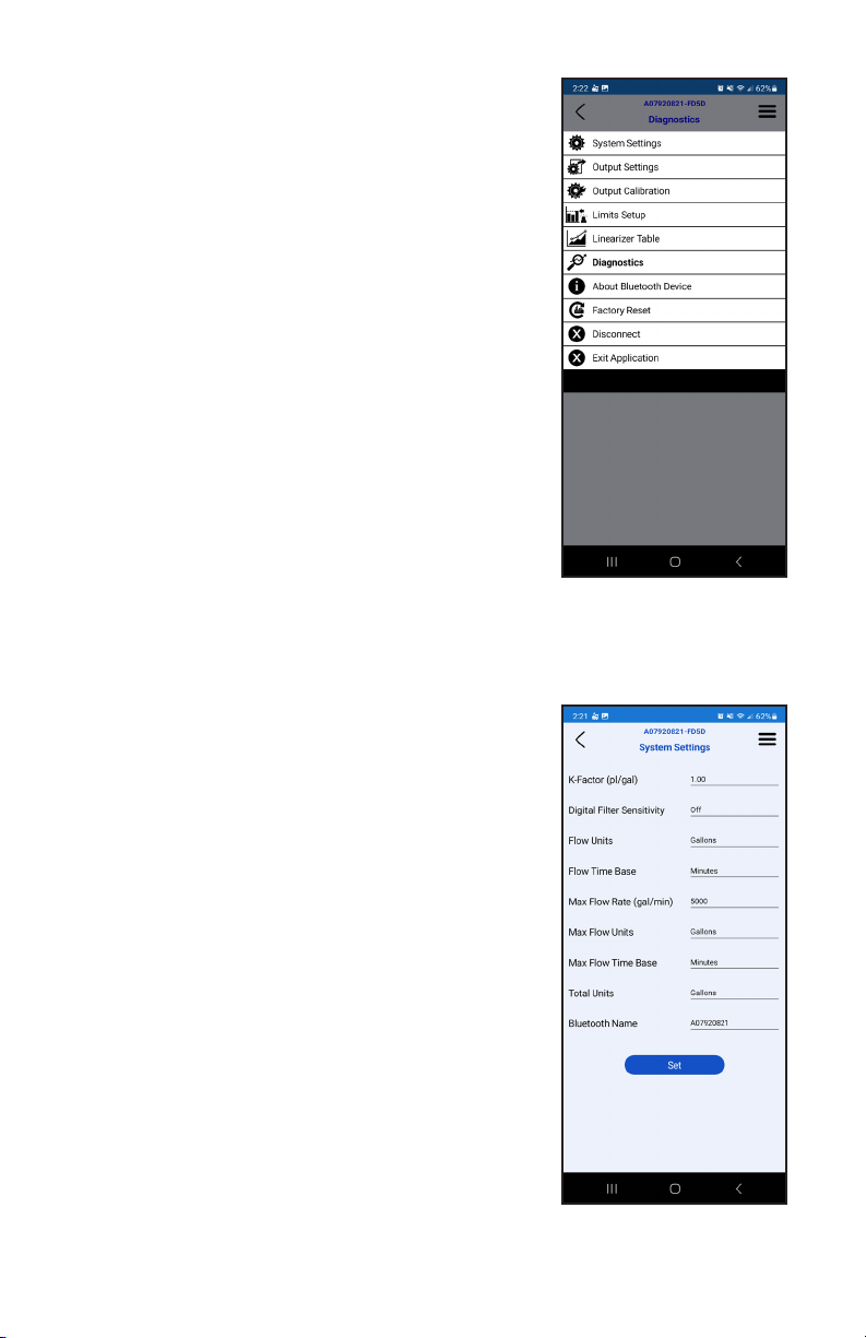
Output Settings: Where outputs can be forced
to certain values or output type can be selected
(Voltage type only)
Output Calibration: Calibrate analog outputs (consult
factory)
Linearizer Table: Allows user to select custom
K-factors for different points in the flow range
Diagnostics: Shows raw input frequency
About Bluetooth Device: Displays device type,
Bluetooth name, firmware version, and serial number
Factory Reset: Defaults all user settings back to
factory settings
Disconnect: Used to disconnect from device
Exit: Closes application
System Settings
This menu allows users to scale the sensor to output
correct analog signal and display correct flow rate
in the desired units and time base. It will also allow for filtering of the output.
(Figure 10)
*After any option is changed press SET for it to
take effect. Use back button on phone to return to
main screen.*
K-Factor: The flow meter scaling factor in pulses/gal
(found on calibration sheet)
Digital Filter: Smooth out erratic input frequency.
Only effects analog signals. There are four options to
choose from:
• Off: No filtering
• Low: Most filtered, low sensitivity. (Corner
frequency ¼ Hz)
• Medium: Medium sensitivity. (Corner frequency
1 HZ)
• High: Least filtered, high sensitivity. (Corner
frequency 10 Hz)
Flow Units: Real time flow rate units
Flow Time Base: Real time flow time base unit
Figure 9: Setup Menu
Figure 10: System
Settings
19
Page 20
Max Flow Rate: The flow rate at which the analog output should be at its max.
Max Flow Units: Selects what unit to scale flow in.
*Flow units will aect Max Flow Rate. Verify both aer changing ow units.
Max Flow Time Base: Can be set to Sec, Min, Hours, and Days.
*Time base will aect the Max Flow Rate. Verify max ow rate is correct aer changing
me base.
Bluetooth Name: The name that will appear when searching for the device.
Connection will be lost after changing the Bluetooth name and will require
reconnection. Name is limited to 19 characters. Some characters on the phone
are invalid to use. Examples: $, %, ^ symbols
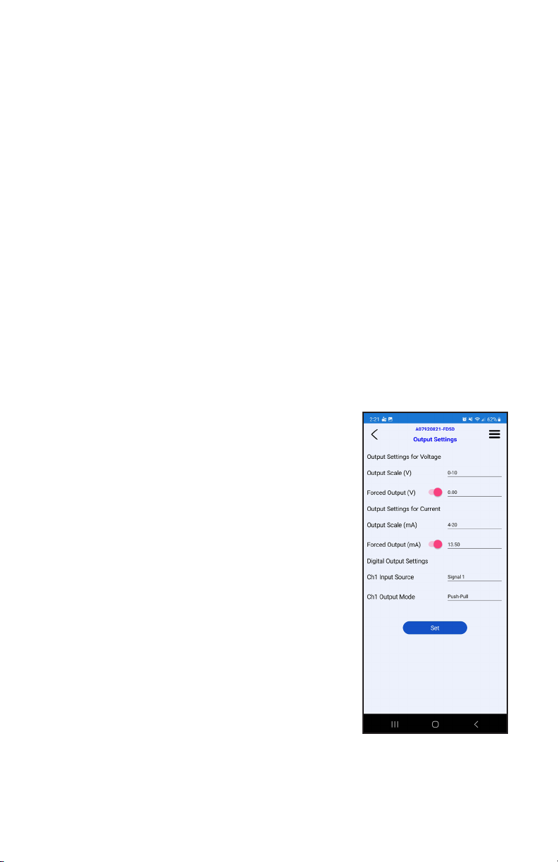
Output Settings
Forced Outputs
This menu will provide the option to force one or both outputs to a certain value.
Along with this ability, Voltage output type will also be selectable. (Figure 5)
To activate, Move the slider to the right. Enter
in desired forced output and press SET to store
information.
*Note: Forced output will not output a value when only
being powered by USB. Informaon will not be stored
unl SET is pressed and forced value will revert back to
previous value or state if output value is outside of the
range.
Forced output limitations: When forcing an output, it
must be in between the analog out specifications and
will go to the third decimal place.
Ex. 4-20mA output Forced output: 6.25mA
0-10V output Forced output: 7.5V
Digital Output Settings
Input Source – User can choose between 5
digital input sources depending on sensor version.
Input sources include: Signal 1, Signal 2, Signal
1+2, Direction, and Limit. See page 16 for further
descriptions.
20
Figure 11: Output
Settings
Page 21
Output Mode – User has the option to select the output type of the signal. The 3
options include: Push-Pull, Sinking (NPN), and sourcing (PNP). See Page 17 for
further descriptions.
Output Calibration
WARNING: Modifying these outputs could result in inaccurate analog signals.
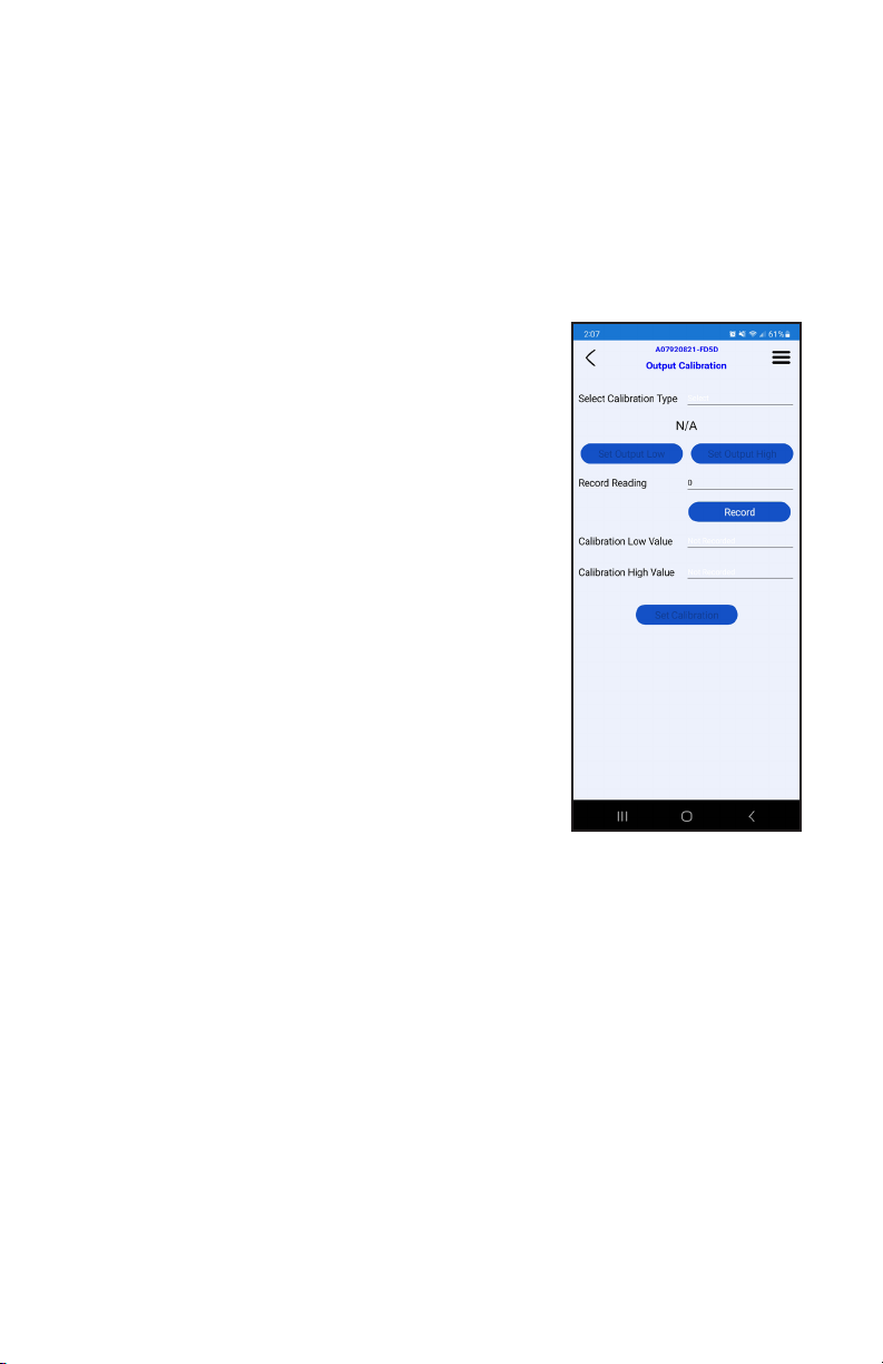
This menu is provided to adjust the sensor analog
output to correspond correctly with the analog output
of the input device.
* This menu is intended for use with slight output
dierences between the sensor output and customer
input device. These values are factory calibrated before
shipping to match meters that are calibrated annually.
Select Calibration Type: From this menu both mA
and Voltage outputs may be calibrated. (Figure 6)
1. Select which output type to be calibrated; mA or
Voltage
2. Press Set Output Low, then enter in the value
on user’s device into Record Reading
a. Ex. If sensor is being calibrated to a
multimeter, enter in reading from multimeter
to Record Reading
3. Press Record button
4. Now press Set Output High to calibrate the
high end of the output
Figure 12: Output
Calibration
5. Enter in High reading from input device to Record Reading
6. Press Record button
7. Verify both Calibration high and low values are correct and press Set
Calibration
8. Use back button on phone to navigate to the main menu
*WARNING: Do not do 2 calibrations in a row. After calibration is finished, exit
the app and restart the device.
21
Page 22
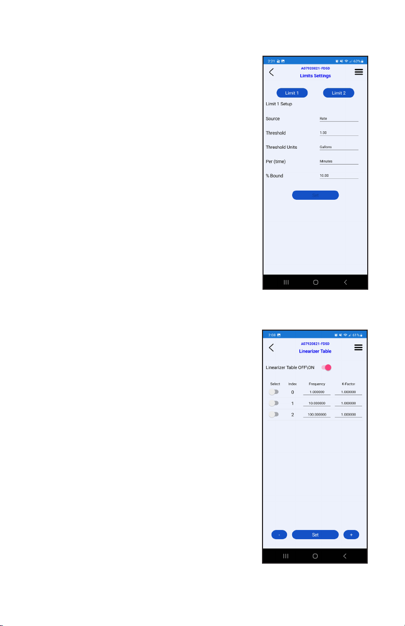
Limits
The limit screen is used to set the parameters that
trigger the outputs. To use this function, set the
Input Source on the Output Settings menu to Limit.
The limit has 4 types of triggers: Rate, Total, Grand
Total, and Cycle Output.
Rate – Output will go high when flow rate is within
the given parameters and low when it goes outside.
Select a threshold/ target rate, then select the
percentage the flow rate that is allowed to drift
from that threshold. Example: a 10% bound on a
threshold of 20 gpm would give a rate range of 1822 gpm.
Total – Output will go high when Total goes above
the threshold value.
Grand Total - Output will go high when Grand
Total goes above threshold value.
Cycle Output – Output will change state between
high and low every time the threshold total is
reached. To achieve one pulse per desired output,
divide that value by 2. For example, to get 1 pulse
per gallon set threshold to 0.5 gallons.
*Cycle Output limited to 5Hz or 300 pulses per minute*
Linearizer
The linearizer function is designed to correct for
devices that will vary in a nonlinear way as a device
changes in flow/frequency. It can take nonlinear
input and change it to a more linear analog output.
(Figure 14)
Ex. Looking at a meter that has a range of 0.5-2 GPM.
If at 0.5 GPM (=100HZ) it has a K-factor of 1800, at 1.5
GPM (=200Hz) it has a K-factor of 1850, and at 2.0 GPM
(=300Hz) it has a K-factor of 1900. Using a linearizer
would ensure the most accurate results over the full
range of ow.
Figure 13: Limits
Figure 14: Linearizer
Table
22
Page 23

Turn On Linearizer: Press the slider to turn the linearizer On and Off. The Slider
will turn pink to indicate it is On. Press the Set button for selection to take place.
Changing Values: To change values in the table, press on the desired data point
that needs changing. Enter in new values and press the Set button to save the
changes.
Entering New Values: To enter in values to the linearizer, press the (+) button.
This will bring up the option to type in a desired frequency and corresponding
K-factor. After values are entered, press Add, this should input the values into
the table. Continue to the next Row and repeat the process for each additional
value needed. There are 10 rows available, but it is not required to fill them all.
When desired amount of points are entered, press SET to save the changes.
Deleting Values: To Remove a value, press the slider next to the row that needs
to be delete. The slider will turn Pink to indicate the row is selected. When all
desired rows are selected, press the ( - ) button to remove them. Press Set to
save the changes.
23
Page 24
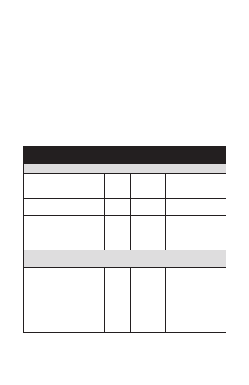
Sensor Modbus Registers
RS485 Settings
• 1 Start Bit
• 8 data Bit
• No Parity Bit
• 1 Stop Bit
• 9600 Baud Rate
Example of Use
Below is a screenshot of the Modbus registers in Modbus Poll. 32-bit float
registers are being read in Big-Endian. Integers (Int) are set up as Signed
values. And the total resets are set up as single write coils.
Name Register Start
Address
Input Registers (read-only register addresses, read funcon byte 0x04)
Raw
Frequency
Input
Flow Rate
(Users units)
Total (Users
Units)
Grand Total
(Users units)
Write Coils (Write coil addresses, read funcon byte 0x05 or 0x000) Single
Coil funcons only
Reset Total 1000 1 Bool 0 - False - Normal
Reset Grand
Total and
Total
5000 2 32 Bit Float (Hz)
5002 2 32 Bit Float User Selected
5004 2 32 Bit Float User Selected
5006 2 32 Bit Float User Selected
1001 1 Bool 0 - False - Normal
Register
Count
Value type Value Units/
Descripon
Mode
1- True - Reset
(0x000)
Mode
1- True - Reset
(0x000)
24
Page 25
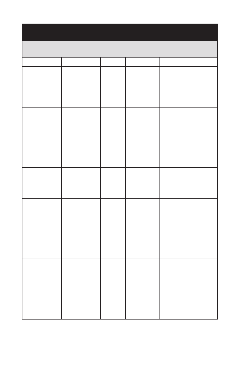
Name Register Start
Address
Holding Registers (read-write register addresses, read funcon byte 0x03,
write funcon byte 0x06 for single or 0x10 for mulple registers)
K-Factor 3000 2 32 Bit Float
Max Flowrate 3002 2 32 Bit Float
Flow Rate
Time Base
Flow Rate
Volume Unit
Max Flow
Time Base
Max Flow
Volume Unit
Total Volume
Units
4000 1 Int 0 - Seconds
4001 1 Int 0 - Pulses
4002 1 Int 0 - Seconds
4003 1 Int 0 - Pulses
4004 1 Int 0 - Pulses
Register
Count
Value type Value Units/
Descripon
1 - Minutes
2 - Hours
3 - Days
1 - Ounces
2 - Gallons
3 - Barrels (Oil)
4 - Cubic Cenmeters
5 - Cubic Meters
6 - Milliliters
7 - Liters
1 - Minutes
2 - Hours
3 - Days
1 - Ounces
2 - Gallons
3 - Barrels (Oil)
4 - Cubic Cenmeters
5 - Cubic Meters
6 - Milliliters
7 - Liters
1 - Ounces
2 - Gallons
3 - Barrels (Oil)
4 - Cubic Cenmeters
5 - Cubic Meters
6 - Milliliters
7 - Liters
25
Page 26

Page 27

WARRANTY/DISCLAIMER
OMEGA ENGINEERING, INC. warrants this unit to be free of defects in materials and workmanship
for a period of 13 months from date of purchase. OMEGA’s WARRANTY adds an additional one (1)
month grace period to the normal one (1) year product warranty to cover handling and shipping
time. This ensures that OMEGA’s customers receive maximum coverage on each product.
If the unit malfunctions, it must be returned to the factory for evaluation. OMEGA’s Customer
Service Department will issue an Authorized Return (AR) number immediately upon phone
or written request. Upon examination by OMEGA, if the unit is found to be defective, it
will be repaired or replaced at no charge. OMEGA’s WARRANTY does not apply to defects
resulting from any action of the purchaser, including but not limited to mishandling, improper
interfacing, operation outside of design limits, improper repair, or unauthorized modification. This
WARRANTY is VOID if the unit shows evidence of having been tampered with or shows evidence
of having been damaged as a result of excessive corrosion; or current, heat, moisture or vibration;
improper specification; misapplication; misuse or other operating conditions outside of OMEGA’s
control. Components in which wear is not warranted, include but are not limited to contact
points, fuses, and triacs.
OMEGA is pleased to offer suggestions on the use of its various products. However,
OMEGA neither assumes responsibility for any omissions or errors nor assumes liability for
any damages that result from the use of its products in accordance with information provided
by OMEGA, either verbal or written. OMEGA warrants only that the parts manufactured by
the company will be as specified and free of defects. OMEGA MAKES NO OTHER WARRANTIES
OR REPRESENTATIONS OF ANY KIND WHATSOEVER, EXPRESSED OR IMPLIED, EXCEPT THAT OF
TITLE, AND ALL IMPLIED WARRANTIES INCLUDING ANY WARRANTY OF MERCHANTABILITY AND
FITNESS FOR A PARTICULAR PURPOSE ARE HEREBY DISCLAIMED. LIMITATION OF LIABILITY:
The remedies of purchaser set forth herein are exclusive, and the total liability of OMEGA with
respect to this order, whether based on contract, warranty, negligence, indemnification, strict
liability or otherwise, shall not exceed the purchase price of the component upon which liability
is based. In no event shall OMEGA be liable for consequential, incidental or special damages.
CONDITIONS: Equipment sold by OMEGA is not intended to be used, nor shall it be used: (1) as
a “Basic Component” under 10 CFR 21 (NRC), used in or with any nuclear installation or activity;
or (2) in medical applications or used on humans. Should any Product(s) be used in or with any
nuclear installation or activity, medical application, used on humans, or misused in any way,
OMEGA assumes no responsibility as set forth in our basic WARRANTY / DISCLAIMER language,
and, additionally, purchaser will indemnify OMEGA and hold OMEGA harmless from any liability or
damage whatsoever arising out of the use of the Product(s) in such a manner.
RETURN REQUESTS/INQUIRIES
Direct all warranty and repair requests/inquiries to the OMEGA Customer Service Department.
BEFORE RETURNING ANY PRODUCT(S) TO OMEGA, PURCHASER MUST OBTAIN AN AUTHORIZED
RETURN (AR) NUMBER FROM OMEGA’S CUSTOMER SERVICE DEPARTMENT (IN ORDER TO AVOID
PROCESSING DELAYS). The assigned AR number should then be marked on the outside of the
return package and on any correspondence.
The purchaser is responsible for shipping charges, freight, insurance and proper packaging to
prevent breakage in transit.
FOR WARRANTY RETURNS, please have the
following information available BEFORE
contacting OMEGA:
1. Purchase Order number under which
the product was PURCHASED,
2. Model and serial number of the product
under warranty, and
3. Repair instructions and/or specific
problems relative to the product.
OMEGA’s policy is to make running changes, not model changes, whenever an improvement is possible.
This affords our customers the latest in technology and engineering.
OMEGA is a registered trademark of OMEGA ENGINEERING, INC.
© Copyright 2015 OMEGA ENGINEERING, INC. All rights reserved. This document may not be copied, photocopied,
reproduced, translated, or reduced to any electronic medium or machine-readable form, in whole or in part, without the prior
written consent of OMEGA ENGINEERING, INC.
FOR NON-WARRANTY REPAIRS,
consult OMEGA
for current repair charges. Have the following
information available BEFORE
contacting OMEGA:
1. Purchase Order number to cover the
COST of the repair,
2. Model and serial number of the product, and
3. Repair instructions and/or specific problems
relative to the product.
27
Page 28

Where Do I Find Everything I Need for
Process Measurement and Control?
OMEGA…Of Course!
Shop online at omega.com
TEMPERATURE
5 Thermocouple, RTD & Thermistor Probes, Connectors, Panels & Assemblies
5 Wire: Thermocouple, RTD & Thermistor
5 Calibrators & Ice Point References
5 Recorders, Controllers & Process Monitors
5 Infrared Pyrometers
PRESSURE, STRAIN AND FORCE
5 Transducers & Strain Gages
5 Load Cells & Pressure Gages
5 Displacement Transducers
5 Instrumentation & Accessories
FLOW/LEVEL
5 Rotameters, Gas Mass Flowmeters & Flow Computers
5 Air Velocity Indicators
5 Turbine/Paddlewheel Systems
5 Totalizers & Batch Controllers
pH/CONDUCTIVITY
5 pH Electrodes, Testers & Accessories
5 Benchtop/Laboratory Meters
5 Controllers, Calibrators, Simulators & Pumps
5 Industrial pH & Conductivity Equipment
28
DATA ACQUISITION
5 Data Acquisition & Engineering Software
5 Communications-Based Acquisition Systems
5 Plug-in Cards for Apple, IBM & Compatibles
5 Data Logging Systems
5 Recorders, Printers & Plotters
HEATERS
5 Heating Cable
5 Cartridge & Strip Heaters
5 Immersion & Band Heaters
5 Flexible Heaters
5 Laboratory Heaters
ENVIRONMENTAL
MONITORING AND CONTROL
5 Metering & Control Instrumentation
5 Refractometers
5 Pumps & Tubing
5 Air, Soil & Water Monitors
5 Industrial Water & Wastewater Treatment
5 pH, Conductivity & Dissolved Oxygen Instruments
M0000/0015
 Loading...