

Page 1
POSITIVE DISPLACEMENT
FLOW METER FOR SOLVENTS
FPD3300 Series
TM
U Aluminum Body
FEP Seals
U
U Stainless Steel Rotors
U
Temperatures up to
80ºC (176ºF)
NPT or BSP Threads
U
U
DIN, JIS or ANSI
Connection (Av
on 1" and Larger Sizes)
ailable
FPD3305D-A
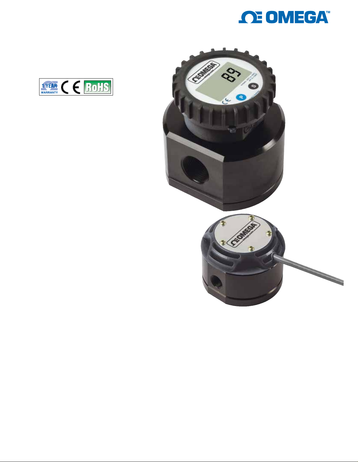
The FPD3300 Series positive
displacement flow meters are
affordable and accurate. One
primary feature is the ability to
maintain consistent accuracy
despite changing viscosity
conditions. The meter’s solid
construction and excellent dynamic
response are well suited to the
measurement of many solv
as well as other non-abrasive
lubricating fluids. Since there is
no need for straight run piping
upstream or downstream of the
flow meter, the FPD3300 flow
meters are simple to use and
to install. The meter has good
resolution and high accuracy at
low flow rates.
ents
SPECIFICATIONS
Accuracy: ±0.5% of reading
Repeatability: ±0.03%
Fitting Type:
NPT:
Female
BSP: “-BSP” option
DIN: “-DIN” option
JIS: “-JIS” option
ANSI: “-ANSI” option
Hall-Effect Sensor Po
24 Vdc (7.5 mA)
Reed Sensor Power:
Output Options:
Pulse Output: Standard
4 to 20 mA Transmitter:
“-D-A” option; no output on battery
powered
“-D” model
wer: 4.5 to
30 Vdc (500 mA)
Both models shown
smaller than actual size.
FPD3303
Display: 7-digit/12 mm (0.47") upper,
7-digit/7 mm (0.28") lower all,
“-D” options
Rate: User defined
Total:
Accumulated-T
Minimum Viscosity: 1 cPs
Maximum Viscosity: 1000 cPs standard
Maximum Pressure: See chart
on page 3
Strainer Size:
Mounting: Shafts must be in a
horizontal plane
Electrical Connections: 2 x 12 mm
(0.08 x 0.47"), fittings included
“-D-A”
Cable Length:
non-display models
Resettable
otal: Non-resettable
See chart on next page
option
1 m (3') stripped ends
1
Mounting: Pipe
P
ower: 4 to 20 mA, “-D-A” models
18 to 30 Vdc display, “-D” models
3 Vdc lithium battery (included)
Liquid Temperature: -40 to 80°C
(-40 to 176°F)
Materials
Body: Aluminum
Enclosure: Polypropylene
Seals: FEP
Rotors: Stainless steel
Fasteners: Stainless steel
Cable Insulation: PVC
Enclosure: NEMA 6 (IP67)
Page 2
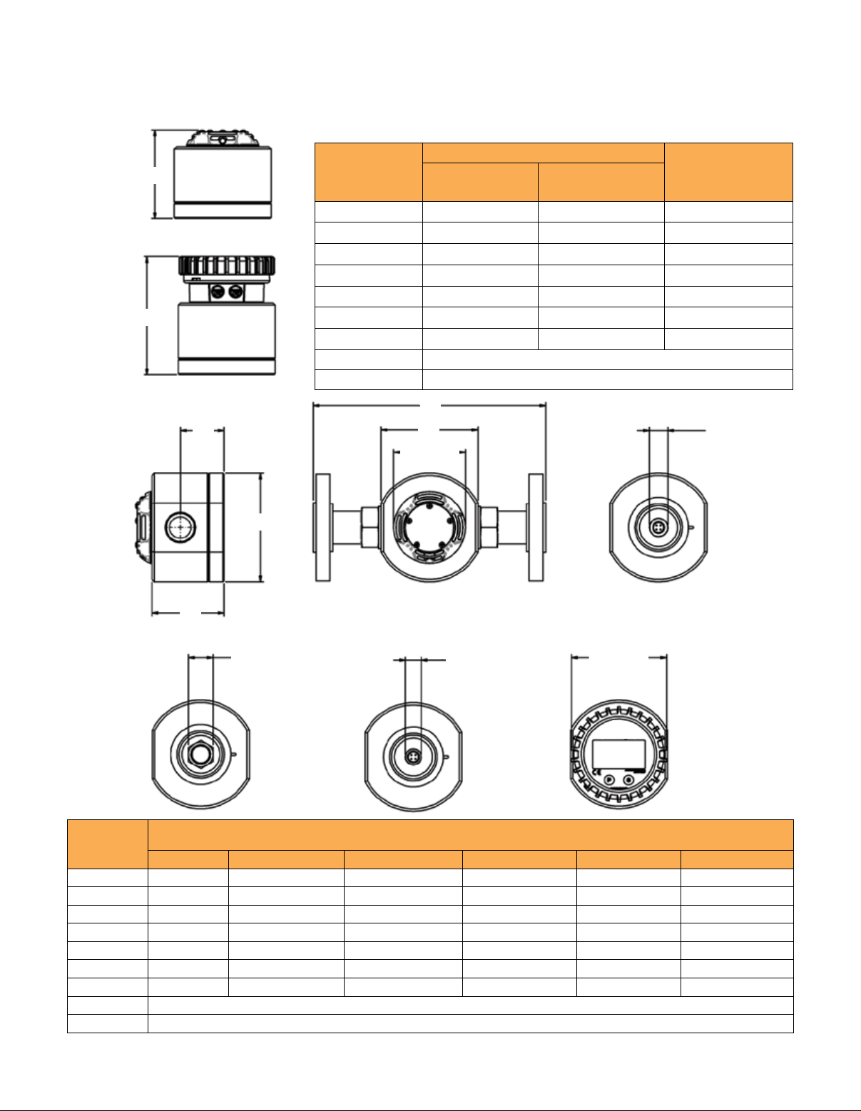
Pulsar and Display Height, F
Dimensions: mm (inch)
F
Model No.
Standar
d -D options
Recommended
Strainer
Standard
F
F
Display (-D options)
E
D
FPD3302
FPD3303
FPD3304
FPD3334
FPD3305
FPD3306
FPD3307
FPD3308
FPD3309
Ø74 (2.9)
B
59 (2.3) 90 (3.5)
59 (2.3) 90 (3.5)
66 (2.6) 97 (3.8)
79 (3.1) 110 (4.3)
92 (3.6) 123 (4.8)
120 (4.7) 151 (5.9)
141 (5.5) 172 (6.7)
See operator’s manual for dimensional drawings
See operator’s manual for dimensional drawings
C
A
200 mesh (74 um)
200 mesh (74 um)
60 mesh (250 um)
60 mesh (250 um)
60 mesh (250 um)
60 mesh (250 um)
60 mesh (250 um)
Ø19 (0.75)
Model No.
FPD3302
FPD3303
FPD3304
FPD3334
FPD3305
FPD3306
FPD3307
FPD3308
FPD3309
* Flanges
25.4 (1) A/F
Ø16 (0.6)
Ø99 (3.9)
Ø = Diameter
Meter and Flange, Dimensions: mm (inch)
ort Size A B C* D E
P
1
⁄4" 71 (2.8) 74 (2.9) N/A 42 (1.7) 25 (1)
1
⁄4" 71 (2.8) 74 (2.9) N/A 42 (1.7) 24 (0.9)
1
⁄2" 81 (3.2) 87 (3.4) N/A 49 (1.9) 28 (1.1)
3
⁄4" 100 (3.9) 112 (4.4) N/A 62 (2.4) 37 (1.5)
1" 100 (3.9) 112 (4.4) 240 (9.4) 75 (3) 45 (1.8)
1
1
⁄2" 120 (4.7) 137 (5.4) 240 (9.4) 103 (4.1) 61 (2.4)
2" 140 (5.5) 163 (6.4) 264 (10.4) 124 (4.9) 72 (2.8)
See operator’s manual for dimensional drawings
See operator’s manual for dimensional drawings
2
Page 3
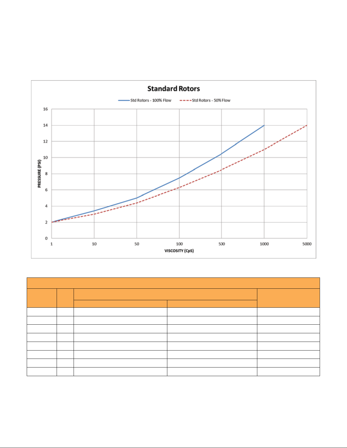
Pressure Drop vs. Viscosity (-HV pressure drop curves can be found in operator’s manual)
100%
50%
To Order
Model No.
FPD3302
FPD3303
FPD3304
FPD3334
FPD3305
FPD3306
FPD3307
FPD3308
Comes complete with lithium battery and operator’s manual.
For units with a battery powered digital display add “-D” to the model number, for an additional charge.
For units with a DC powered digital display and 4 to 20 mA output add “-D-A” to the model number, for an additional charge.
For units with BSP connections add “-BSP” to the model number, no additional charge.
For units with DIN flanges add “-DIN” to the model number, for an additional charge (1" and larger only).
For units with JIS flanges add “-JIS” to the model number, for an additional charge (1" and larger only).
For units with ANSI flanges add “-ANSI” to the model number, for an additional charge (1" and larger only).
For units with high viscosity rotors add “-HV” to the model number, for an additional charge.
Port
Size
< 5 cPs > 5 cPs
1
⁄4" 2 to 100 LPH (0.5 to 26 GPH) 0.5 to 100 LPH (0.13 to 26 GPH) 1000 (6895)
1
⁄4" 25 to 500 LPH (6.6 to 132 GPH) 15 to 500 LPH (4 to 132 GPH) 1001 (6895)
1
⁄2" 3 to 25 LPM (0.8 to 6.6 GPM) 2 to 30 LPM (0.5 to 8 GPM) 2000 (13790)
3
⁄4" 8 to 70 LPM (2 to 18.5 GPM) 3 to 80 LPM (0.8 to 21 GPM) 2001 (13790)
Flow Range
1" 10 to 100 LPM (2.6 to 26 GPM) 6 to 120 LPM (1.6 to 32 GPM) 2002 (13790)
1
1
⁄2" 15 to 235 LPM (4 to 62 GPM) 10 to 250 LPM (2.6 to 66 GPM) 1200 (8274)
2" 15 to 500 LPM (4 to 130 GPM) 16 to 500 LPM (4 to 130 GPM) 1001 (6895)
3" 60 to 600 LPM (15.8 to 158 GPM) 20 to 733 LPM (5.3 to 193 GPM) 175 (1206)
3
Maximum
Pressure
psi (Kpa)
 Loading...