

Page 1
User’s Guide
Shop online at
omega.com
e-mail: [email protected]
For latest product manuals:
www.omegamanual.info
®
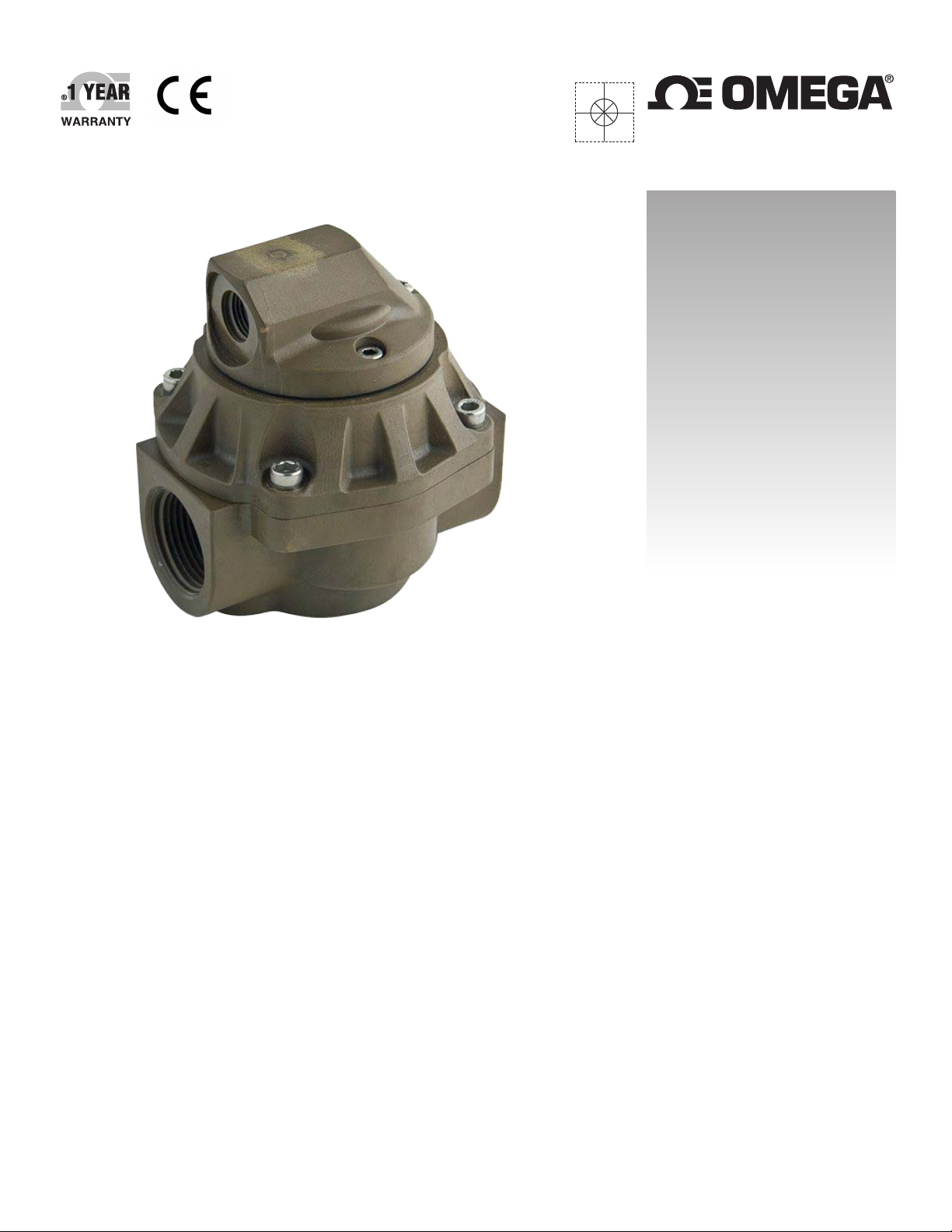
FPD3100 Series
1/4" - 1" Oval Gear Flowmeter
for use with Corrosive Chemicals
Page 2

omega.com [email protected]
Servicing North America:
U.S.A.: Omega Engineering, Inc., One Omega Drive, P.O. Box 4047
Stamford, CT 06907-0047 USA
Toll-Free: 1-800-826-6342 (USA & Canada only)
Customer Service: 1-800-622-2378 (USA & Canada only)
Engineering Service: 1-800-872-9436 (USA & Canada only)
Tel: (203) 359-1660 Fax: (203) 359-7700
e-mail: [email protected]
For Other Locations Visit omega.com/worldwide
The information contained in this document is believed to be correct, but OMEGA accepts no liability for any errors it contains, and reserves
the right to alter specifications without notice.
WARNING: These products are not designed for use in, and should not be used for, human applications.
Page 3

index
Installation
Pre-installation checks
Operating Principle
Installation Procedure
Maintenance Procedure
Disassembly
Reassembly
Flowmeter Specifications
Flowmeter Specifications
Electrical Specifications
Service
………………………………………………………….
………………………………………………………….
………………………………………………………….
………………………………………………………….
………………………………………………………….
………………………………………………………….
………………………………………………………….
Page 4
Page 5
Page 5
Page 6
Page 6
Page 7
Page 8
Digital Displays
Troubleshooting Guide
Exploded Diagram
Spare Parts Kits
Wetted Parts
General
Pressure Drop Graphs
Dimensional Diagrams
………………………………………………………….
………………………………………………………….
………………………………………………………….
………………………………………………………….
………………………………………………………….
………………………………………………………….
Page 9
Page 9
Page 10-11
Page 12
Page 12 ………………………………………………………….
Page 13
Page 14-15
3
Page 4
To the Owner
Please read and retain this instruction manual to assist you in the operation and maintenance
of this product.
This manual contains connection and operating instructions for the FPD Flowmeter series
with Pulse outputs.
Models with a Liquid Crystal Display have an additional LCD instruction manual supplied. If
you need further assistance, contact your local representative or distributor for advice.
This Flow Meter has incorporated the oval rotor principal into its design. This is proven to be a
reliable and highly accurate method of measuring flow.
Exceptional repeatability and high accuracy over a wide range of fluid viscosities and flow
rates are features of the oval rotor design.
With a low pressure drop and high pressure rating oval rotor flow meters are suitable for both
gravity and (in-line) pump applications.
IMPORTANT INFORMATION
FLUID COMPATABILITY
Before use, confirm the fluid to be
used is compatible with the meter.
Refer to Industry fluid compatibility
charts or consult your local representative for advice.
STRAINER
To prevent damage from dirt or
foreign matter it is recommended that
a Y or Basket type mesh strainer be
installed as close as
possible to the inlet side of the meter.
When a strainer is installed it
should be regularly inspected and
cleaned. Failure to keep the strainer
clean will dramatically effect flow meter performance.
Contact your local representative for advice.
AIR PURGE / LINE PRESSURE
To prevent damage caused by air purge
slowly fill the meter with fluid.
To reduce pressure build-up turn off
the
at the end of each day.
REED SWITCH
The reed switch can cause inaccurate
rate counts when used with high speed
counters.
It is advised that a low speed counter is
used or alternatively a denounce circuit
be installed.
4
Page 5
OPERATING PRINCIPLE
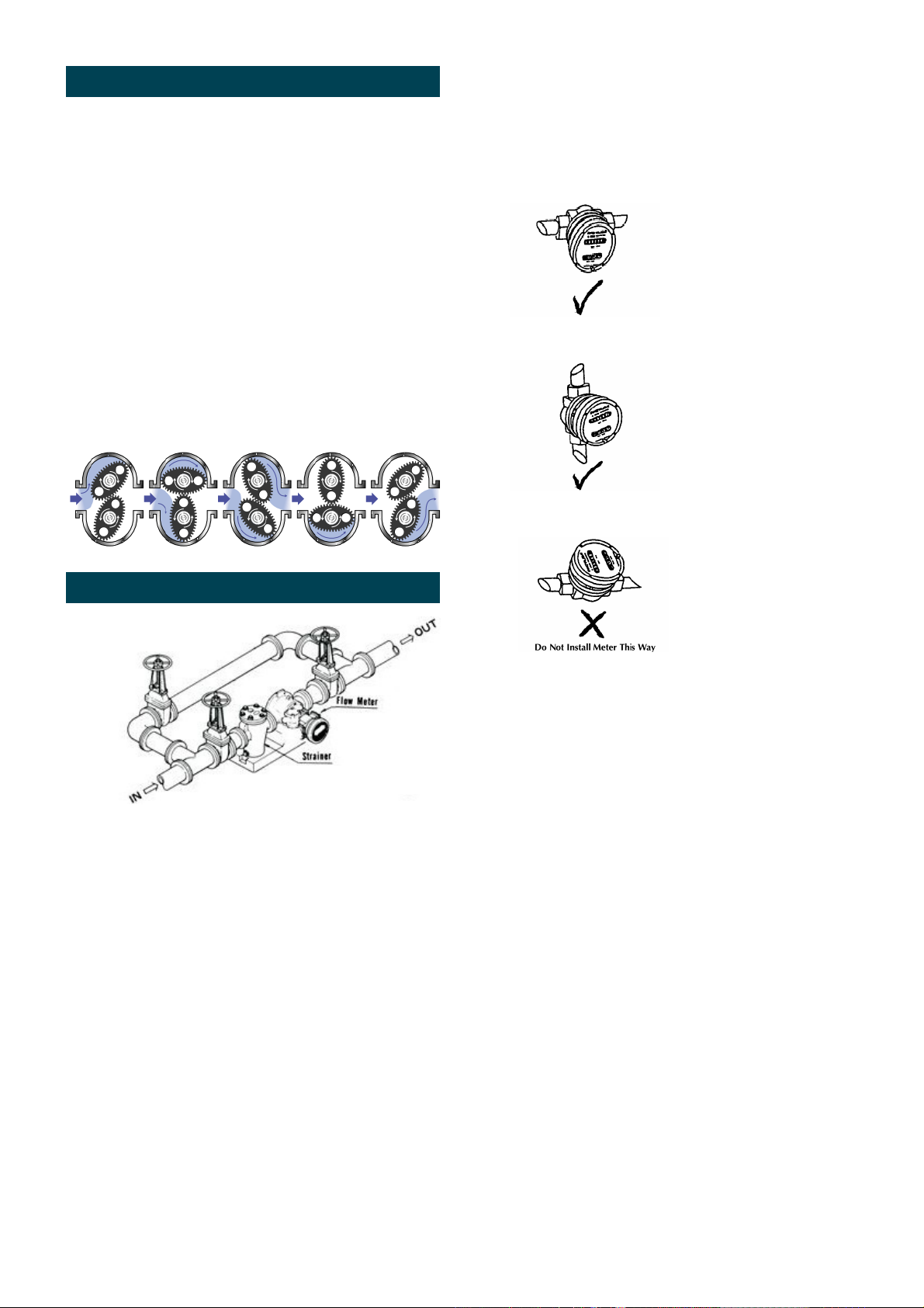
Fluid passing through the meter causes the rotors to
turn, as shown below.
One of the rotors (the active rotor) is fitted with
magnets.
The passing of the magnets are picked up by the
sensing elements (Reed and Hall Effect sensors)
located in the Pulser Circuit Board.
The excitation of these switches provides a ‘Raw
Pulse Output’ which relates to the K-Factor.
(e.g. KF 36 = 36 pulses per litre of fluid passed)
This Pulse Output Signal can either be fed directly to
an external receiving element (e.g. Data Logger or
PLC) or alternatively to an LC Display which conditions the Pulse input signal to display volume of fluid
passed. (e.g. Display 1 Litre per for every 36 pulses
received)
5. Note: The Flowmeter can accept flow in any
direction.
6. The meter can be installed in any orientation as
long as the meter shafts are in a horizontal plane.
(Refer to diagram below for correct installation)
.
INSTALLATION PROCEDURE
1. It is recommended that when setting up pipe work
for meter installations, a bypass line be included in
the design. This provides the facility for a meter to
be removed for maintenance without interrupt ing
production. (see figure above)
2. Use thread sealant on all pipe threads.
3. For pump applications ensure pipe work and
Meter have the appropriate working pressure
rating to match the pressure output of the pump.
Refer to Meter Specifications section for further
details.
Note: Incorrect installation can cause premature
wear of meter components.
The LC display may removed by loosening the 4
mounting screws and be orientated as required.
7. Do not over tighten meter connections. .
8. It is important that after initial installation you
fill the line slowly, high speed air purge could
cause damage to the rotors.
9. Test the system for leaks.
10. Check the strainer for swarf or foreign material,
after the first 200 litres check periodically,
particularly if the flow rate is noted to be
decreasing.
4. Install a wire mesh strainer, Y or basket type
as close as possible to the inlet side of the meter.
Meter 1/4” 74 micron / 200 mesh
Meter 1” 250 micron / 60 mesh
5
Page 6
Maintenance Procedures
Disassembly
Ensure that the fluid supply to the meter is disconnected, and the line pressure is released before disassembly, with the exception for repair or
maintenance to the LC Display or PCB where
there is no necessity to isolate the meter from flow.
Refer to the exploded parts diagram on subsequent
pages for item numbers.
1) Pulse Caps Models: Undo the conduit connector,
remove pulse cap (item 9) and remove the wires
from the pulse terminal board (item 5).
2) Standard LC Display: Mark the display orientation
with a marking pen, unscrew the four large screws
on top of the LC Display. Carefully separate the
LC Display from the plastic housing and
disconnect the wires from the pulse terminal
block. (Refer to additional LCD instruction manual
accompanying these instructions). Remove the
mounting adaptor plate and gasket.
3) Loosen the cap head screws (Item 7) that hold
down the meter cap (Item 4), remove the screws,
washers and lift off the cap.
4) Remove the o-ring (Assembly Item 2) from the o-
ring groove in the meter cap (Assembly Item 4).
5) Remove rotors (Item 3).
7) Insert the cap head screws (Item 7) and tighten i n
a diagonal sequence 1, 3, 2, 4, etc.
8) The replacement of cables and connectors are
a reversal of the disassembly procedure, replace
conduit fitting if required.
When replacing the Standard LC Display confirm
the orientation marks made on disassembly are
aligned then screw the register into place.
9) Test the meter by turning the rotors with a finger
or by applying very low air pressure (no more
than a good breath) to one end of the meter,
before returning the meter to the line.
Reassembly
1) Before reassembling check the condition of the
rotors (replace if necessary).
2) Check that the smooth side of the rotors (not the
plug side) is facing you when inserting the rotors,
the smooth side of the rotor is the magnet side.
There is no difference between rotor one or rotor
two.
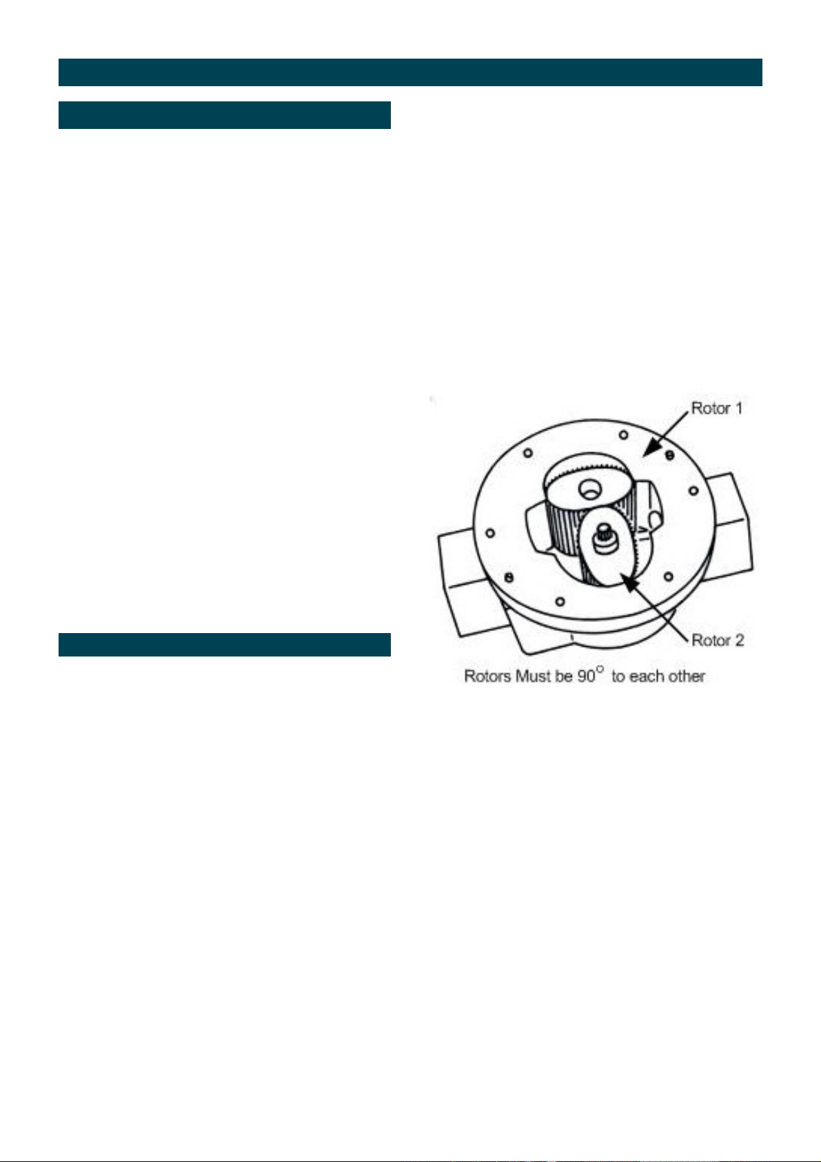
3) Replace the rotors (Item 3) onto the shafts at 90
degrees to each other (refer Fig) and check
their operation by turning either of the rotors.
If the rotors are not in mesh correctly or do
not move freely, remove one of the rotors and
replace correctly at 90 degrees to the other rotor.
4) Re-check the operation of the rotors
5) Replace the o’ring (Item 2) into groove in the
meter cap, if the o’ring has grown or is damaged
in any way replace it with a new part.
6) Replace the meter cap making sure that the
locating pin in the body lines up with the hole in
the meter cap.
6
Page 7
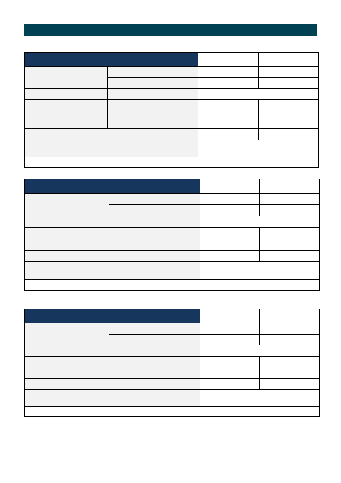
FLOWMETER SPECIFICATIONS
Series FPD3102
Flow Range
K-Factor Pulses per unit of measure
Max Temperature
Maximum Operating Pressure
Accuracy of Reading
1. Conforms to Directive 97/23/EC—Cat 1
Below 5 cP
5 to 1000 cP
without Digital Display
with –D or –D-A Digital Display
1
Series FPD3103
Flow Range
Nominal K-Factor Pulses per unit of measure
Below 5 cP
5 to 1000 cP
Metric US
2 to 100 LPH 0.5 to 26 GPH
0.5 to 100 LPH 0.13 to 26.4 GPH
Refer to Flowmeter Data Plate
-40°C - 80°C -40°F - 176°F
-20°C - 60°C -4°F - 140°F
500 kPa 75 psi
±0.25% available with reduced flow range
±0.5% standard
Metric US
25 to 500 LPH 6.6 to 132 GPH
15 to 500 LPH 4 to 132 GPH
Refer to Flowmeter Data Plate
Max Temperature
without Digital Display
with –D or –D-A Digital Display
Maximum Operating Pressure
1
Accuracy of Reading
1. Conforms to Directive 97/23/EC—Cat 1
Series FPD3105
Flow Range
Nominal K-Factor Pulses per unit of measure
Max Temperature
Maximum Operating Pressure
Accuracy of Reading
Below 5 cP
5 to 1000 cP
without Digital Display
with –D or –D-A Digital Display
1
-40°C - 80°C -40°F - 176°F
-20°C - 60°C -4°F - 140°F
500 kPa 75 psi
±0.25% available with reduced flow range
±0.5% standard
Metric US
8 to 70 LPM 2 to 18.5 GPM
3 to 80 LPM 0.8 to 21 GPM
Refer to Flowmeter Data Plate
-40°C - 80°C -40°F - 176°F
-20°C - 60°C -4°F - 140°F
1000 kPa 150 psi
±0.25% available with reduced flow range
±0.5% standard
1. Conforms to Directive 97/23/EC—Cat 1
7
Page 8
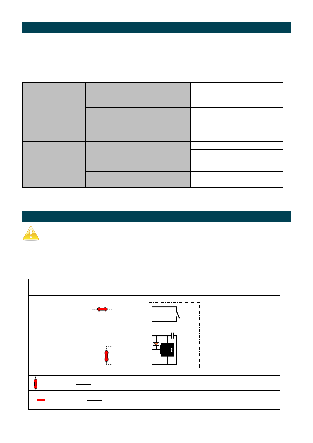
ELECTRICAL SPECIFICATIONS
Pulser Board/Sensor Specifications
There are two sensors on each PCB
1x Reed Switch 1x Hall Effect Output
Output Signals Standard Pulse Meter 2x Digital (Square Wave)
Current Maximum2 500mA
Reed Switch2
(Mechanical Sensor)
Hall Effect IC2
(Electronic Sensor)
2. Voltage & current specifications apply per sensor (not combined).
3. Contact rating maximum is 10W. Neither current nor voltage maximums should be exceeded in achieving this.
Voltage Maximum2 30V DC
Contact Rating Maximum
Maximum Output Current
Operating Voltage 4.5V to 24V DC
Transistor Type Open-Collector NPN
3
10W
7.5mA Maximum Sensor Supply Current
25mA
WIRING DIAGRAM
Please read this information carefully before installation
Hall Effect:
Hall effect sensors require an external pull up resistor to be fitted by the installer for correct operation. Powering a Hall effect
sensor without a resistor wired between the supply voltage and the signal line will result in damage to the sensor.
Reed Switch:
In order to protect the reed switch from over current, and to maximise life expectancy, we recommend limiting the current
through the switch by fitting a series resistor in between the signal leg and the PLC/signal sensing device.
FPD3105 Pulser Board
V1+
Series
Res Ω**
Pull up
Res Ω*
* Pulser boards are not fitted with a pull up resistor. Consult sensor specifications on page 4 for selection of appropriate resistance.
** Pulser boards are not fitted with a current limiting resistor. For 12VDC we recommend a1kΩ resistor. For 24VDC, we recommend a
1.8k-2.2kΩ resistor.
1
2
3
4
5
V1-
GND
SIG2
Vcc
1x Reed and 1x Hall Effect
Reed
Switch
Hall
HE
Effect
8
Page 9
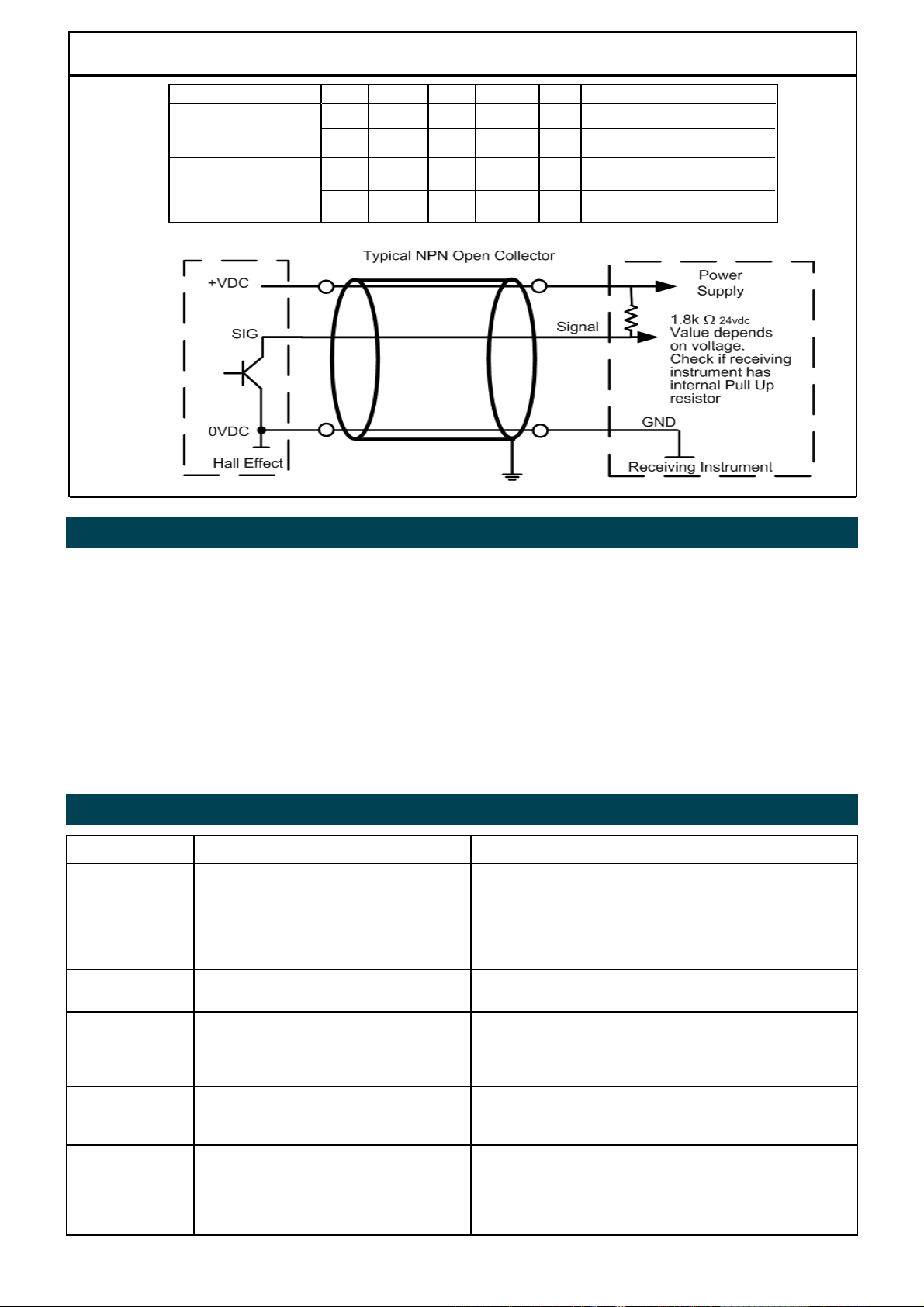
FPD3102/FPD3103 Wiring Connections and Diagram
Output Type Wire Function Wire Function Wire Function Note
Reed/Hall Reed Green Yellow
No Polarity Required
Hall
Reed/Hall LCD Reed Black Black
Hall
Red
+ VDC Black Gnd (0V) White Signal
Red + VDC Black Gnd (0V) White Signal
NPN Open Collector
Connects to LCD
NPN Open Collector
DIGITAL DISPLAYS
The Flow meter series is supplied with either a Blind Pulser and Digital Display option.
If the Flow meter is supplied with an LC Display fitted, please consult the appropriate Instruction Manual, as
advised below, for all programming and wiring instructions.
Analog Output (4-20mA)
Analog outputs are available as an auxiliary display signal by including either of the following LC displays with your flowmeter.
These may be fitted to the meter or remote (wall mount) types.
FPD3100-D 12mm LC Display (No output options)
FPD3100-D-A 12mm LC Display with analog output module
Troubleshooting Guide
Problem Cause Remedy
Fluid will not flow
through meter
Reduced flow
through meter
Meter reading
inaccurate
a) Foreign matter blocking rotors
b) Line strainer blocked
c) Damaged rotors
d) Meter connections over tightened
e) Fluid is too viscous
a) Strainer is partially blocked
b) Fluid is too viscous
a) Fluid flow rate is too high or too low
b) Air in fluid
c) Excess wear caused by incorrect installation
a) Dismantle meter, clean rotors (strainer must be fitted in
line)
b) Clean strainer
c) Replace rotors (Strainer must be fitted in line)
d) Re-adjust connections
e) See specifications for maximum viscosity
a) Clean strainer
b) See specifications for maximum viscosity
a) See specifications for minimum and maximum flow rates
b) Bleed air from system
c) Check meter body and rotors. Replace as required. Refer
to installation instructions
Meter not giving a
pulse signal
LCD register not
working
a) Faulty hall effect sensor
b) Faulty reed switch
c) Magnets failed
a) Battery not connected properly
b) Battery flat
c) Faulty wiring connections
d) Faulty LC Display
e) Faulty connection from LC Display
a) Replace PCB Board
b) Replace PCB Board
c) Replace magnets
a) Check battery connections
b) Replace battery
c) Check wiring for loose or faulty connections
d) Replace LC Display
e) Check wiring connections
9
Page 10
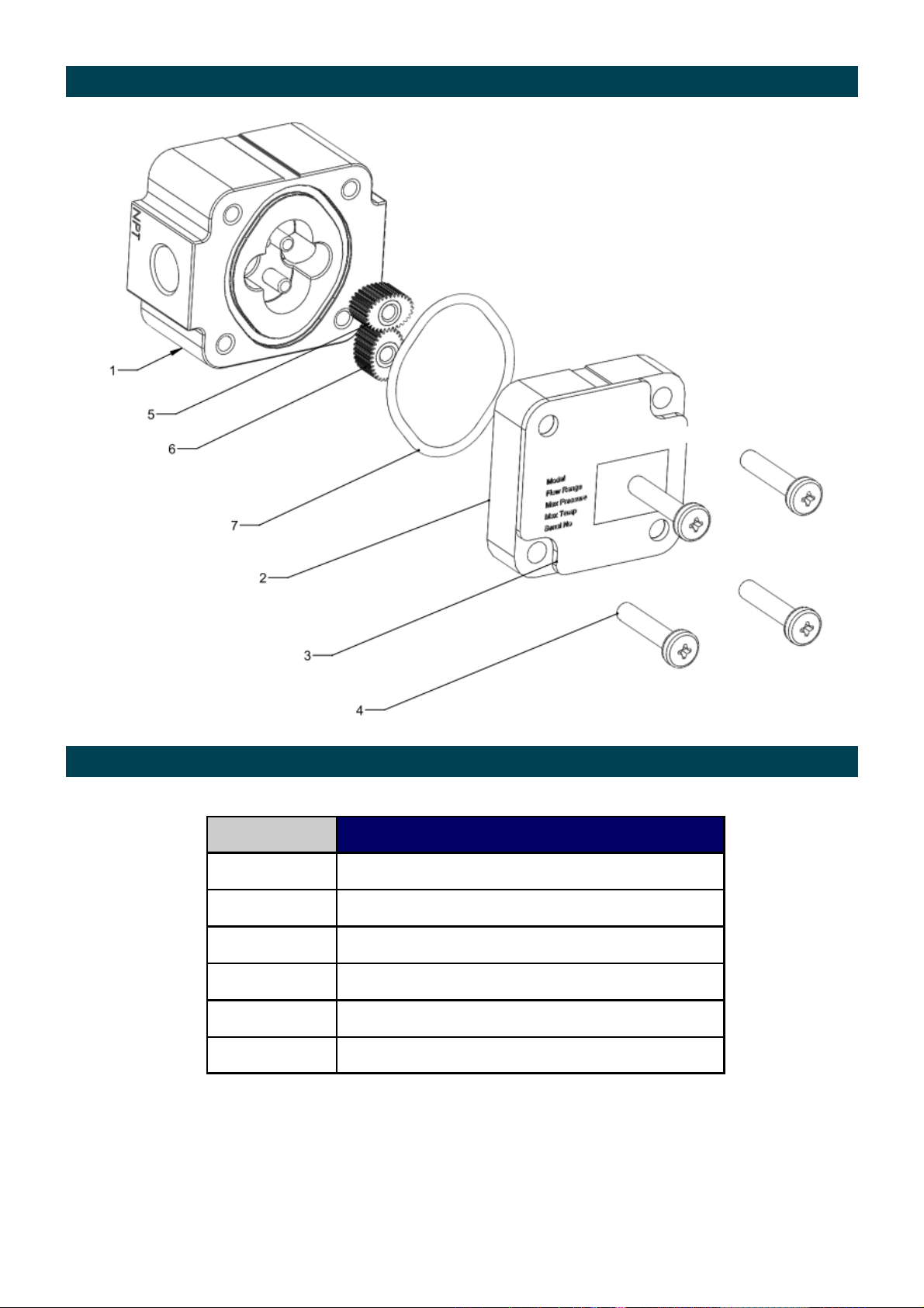
EXPLODED DIAGRAM Models 3102 and 3103
PARTS IDENTIFICATION
Item No. Part Description
1
2
3
4
5 & 6
7
Meter Body
Meter Cap (PCB)
Legend Plate
Meter Cap Mounting Screws
Rotors
0-Ring
10
Page 11
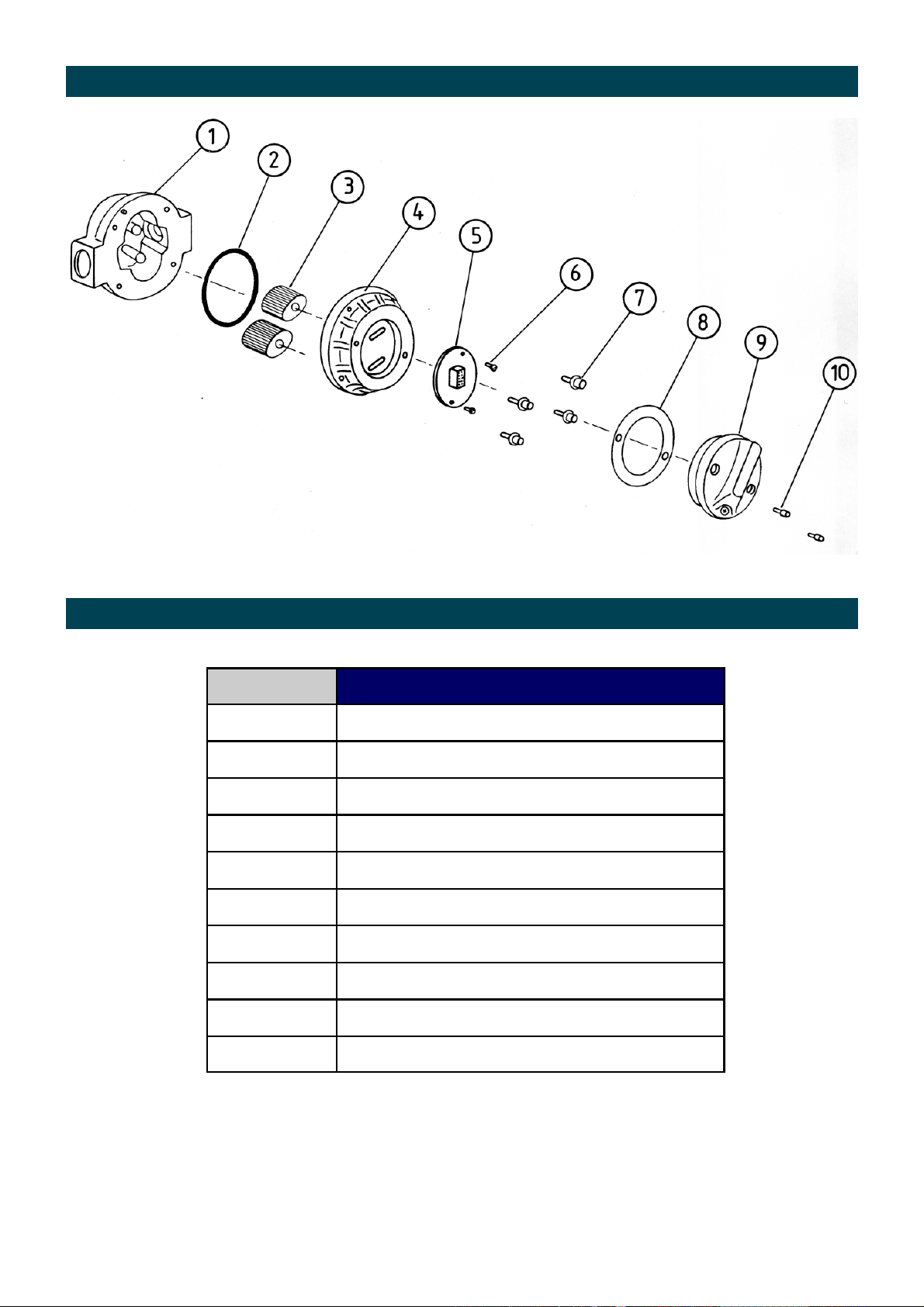
EXPLODED DIAGRAM Models 3105
PARTS IDENTIFICATION
Item No. Part Description
1
2
3
4
5
6
7
8
9
10
Meter Body
0-Ring
Rotors
Meter Cap
Printed Circuit Board
PCB Mounting Screws
Meter Cap Screws
Pulser Cap Gasket
Pulser Cap
Pulser Cap Screws
11
Page 12
SPARE PARTS KITS
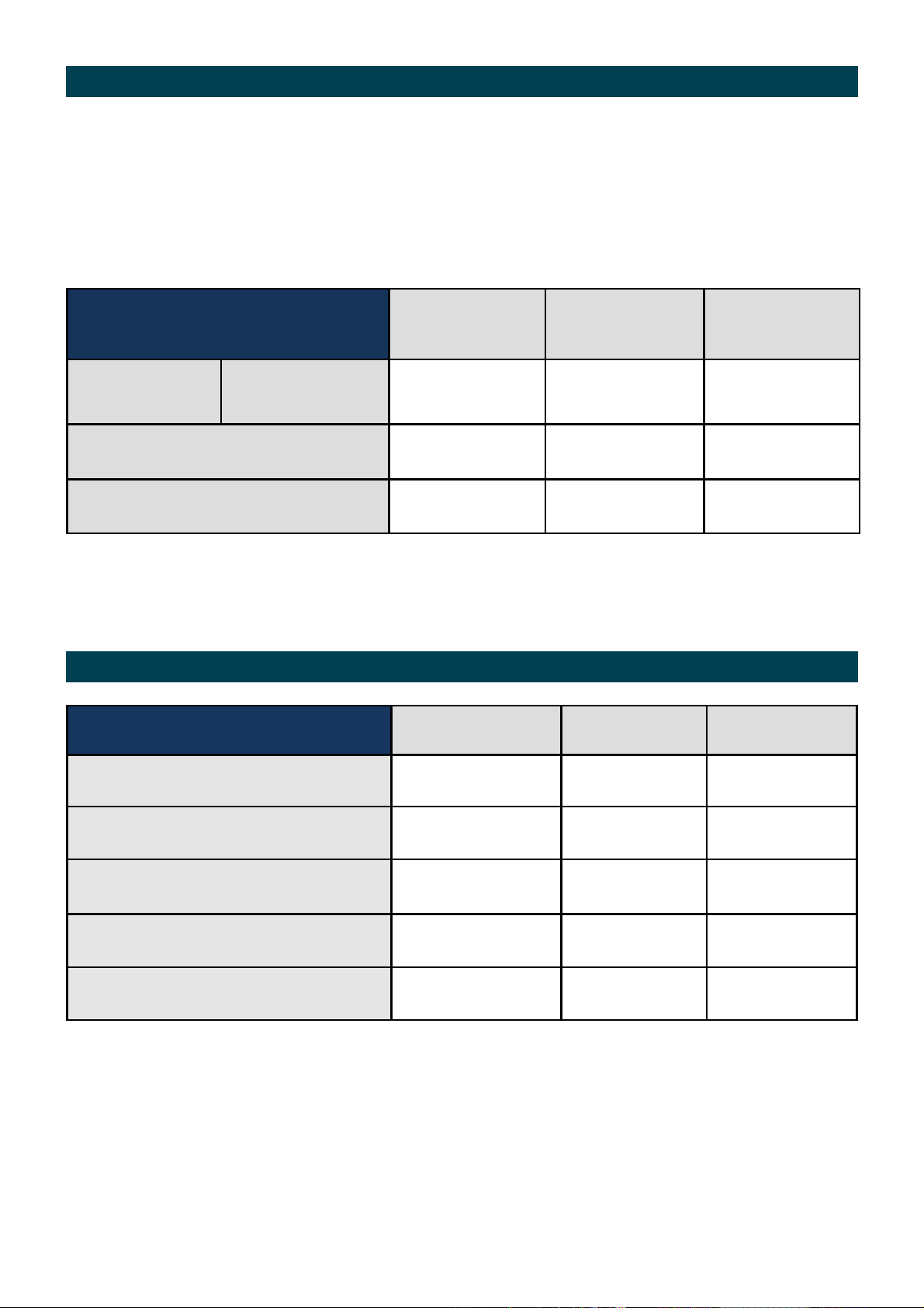
There are 4 Spare Kit options available for the purchase of replacement components:
Pulser Kit (PKit) - Replacement PCB.
Rotor Kit (RKit) - Complete Rotor assembly
Seal Kit (SKit) - Complete set of O-Rings/Gaskets
SPARES KIT FPD3102 FPD3103 FPD3105
PULSER KIT
ROTOR KIT
SEAL KIT
Reed / Hall Effect FPD3102-Pulser FPD3103-Pulser FPD3105-Pulser
FPD3102-Rotor FPD3103-Rotor FPD3105-Rotor
FPD3102-Seal FPD3103-Seal FPD3105-Seal
WETTED PARTS
METER COMPONENTS FPD3102 FPD3103 FPD3105
METER BODY
METER CAP
PPS PPS PPS
PPS
PPS
PPS
ROTORS
ROTOR SHAFTS
O-RINGS
K - FEP/PTFE Encapsulated
FFKM - Perfluoroelastomer
PPS - Polyphenylene Sulphide (PPS Resin)
PPS PPS PPS
Hastelloy C Hastelloy C Hastelloy C
FFKM FFKM K
12
Page 13
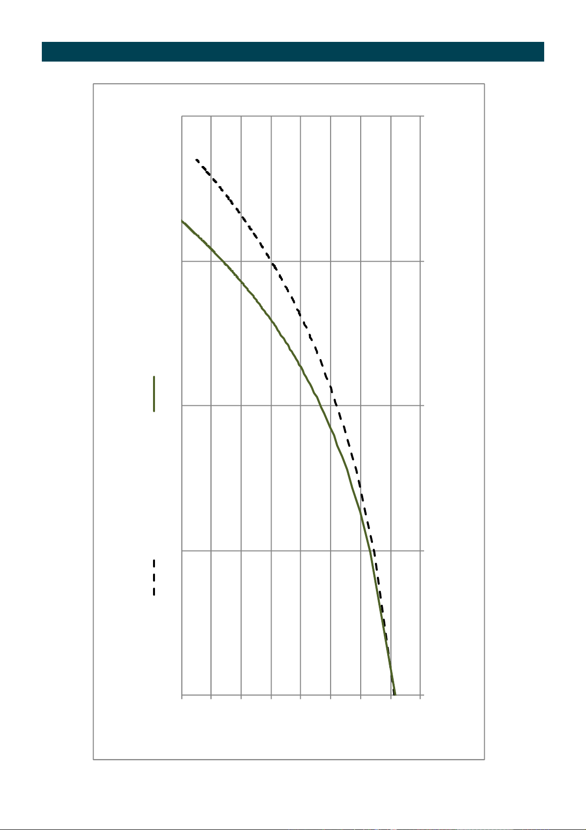
PRESSURE DROP v VISCOSITY
0
2
4
6
8
10
12
14
16
1 10 100 1000 10000
PRESSURE (psi)
VISCOSITY (cps)
STANDARD ROTORS
Std Rotors - 50% Flow Std Rotors - 100% Flow
13
Page 14
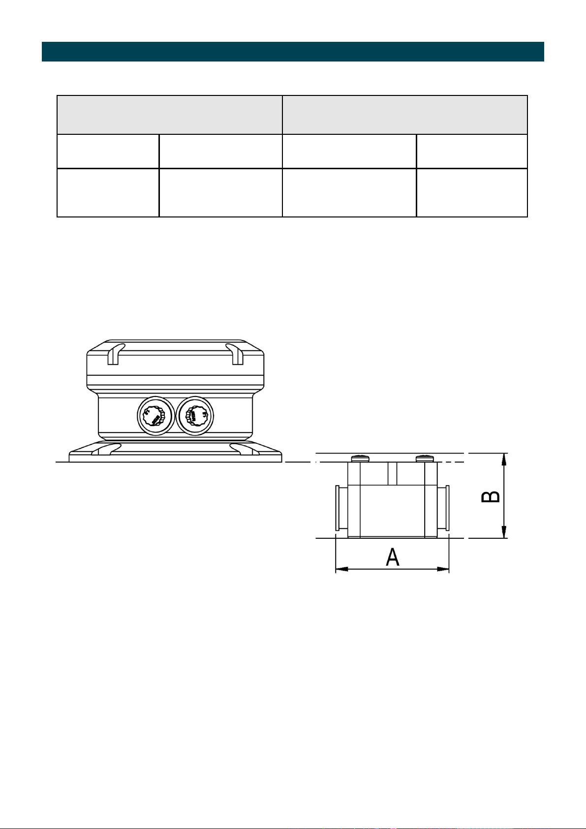
Meter Dimensions Models 3102 and 3103
Face to Face Dimensions (A) Register Height (B)
RC / NPT
64mm
Digital Display
Type -D or -D-A
Pulser
Digital Display
Types –D and –D-A
Pulser
59mm
116mm
14
Page 15
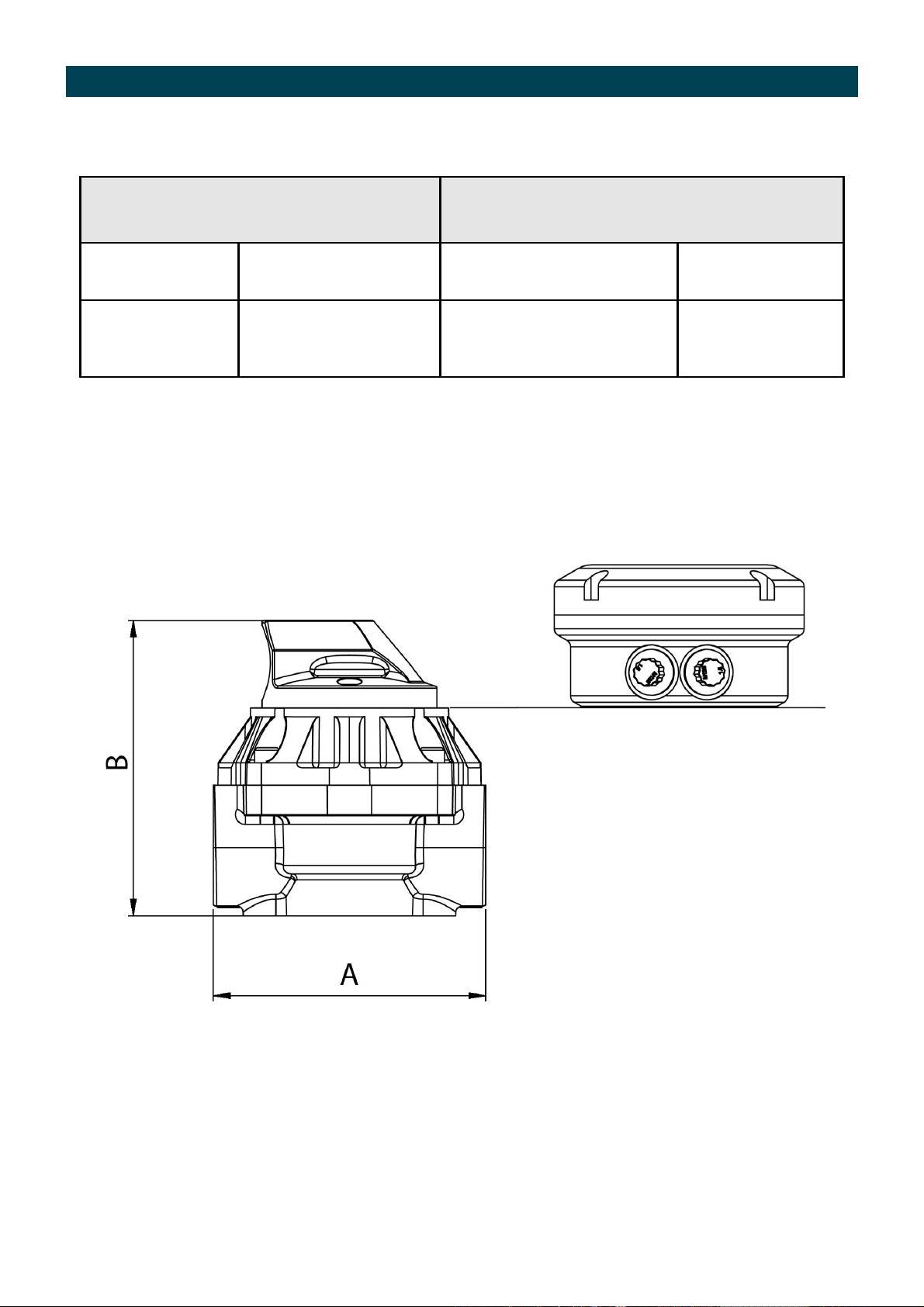
Meter Dimensions Models 3105
Face to Face Dimensions (A) Register Height (B)
RC / NPT
109mm
Pulser
Pulser
Digital Display
Types –D and –D-A
Digital Display
Type -D or -D-A
119mm
141mm
15
Page 16

WARRANTY/DISCLAIMER
OMEGA ENGINEERING, INC. warrants this unit to be free of defects in materials and workmanship for a
period of 13 months from date of purchase. OMEGA’s WARRANTY adds an additional one (1) month
grace period to the normal one (1) year product warranty to cover handling and shipping time. This
ensures that OMEGA’s customers receive maximum coverage on each product.
If the unit malfunctions, it must be returned to the factory for evaluation. OMEGA’s Customer Service
Department will issue an Authorized Return (AR) number immediately upon phone or written request.
Upon examination by OMEGA, if the unit is found to be defective, it will be repaired or replaced at no
charge. OMEGA’s WARRANTY does not apply to defects resulting from any action of the purchaser,
including but not limited to mishandling, improper interfacing, operation outside of design limits,
improper repair, or unauthorized modification. This WARRANTY is VOID if the unit shows evidence of
having been tampered with or shows evidence of having been damaged as a result of excessive corrosion;
or current, heat, moisture or vibration; improper specification; misapplication; misuse or other operating
conditions outside of OMEGA’s control. Components in which wear is not warranted, include but are not
limited to contact points, fuses, and triacs.
OMEGA is pleased to offer suggestions on the use of its various products. However,
OMEGA neither assumes responsibility for any omissions or errors nor assumes liability for
any damages that result from the use of its products in accordance with information provided
by OMEGA, either verbal or written. OMEGA warrants only that the parts manufactured by the
company will be as specified and free of defects. OMEGA MAKES NO OTHER WARRANTIES OR
REPRESENTATIONS OF ANY KIND WHATSOEVER, EXPRESSED OR IMPLIED, EXCEPT THAT OF
TITLE, AND ALL IMPLIED WARRANTIES INCLUDING ANY WARRANTY OF MERCHANTABILITY
AND FITNESS FOR A PARTICULAR PURPOSE ARE HEREBY DISCLAIMED. LIMITATION OF
LIABILITY: The remedies of purchaser set forth herein are exclusive, and the total liability of
OMEGA with respect to this order, whether based on contract, warranty, negligence,
indemnification, strict liability or otherwise, shall not exceed the purchase price of the
component upon which liability is based. In no event shall OMEGA be liable for
consequential, incidental or special damages.
CONDITIONS: Equipment sold by OMEGA is not intended to be used, nor shall it be used: (1) as a “Basic
Component” under 10 CFR 21 (NRC), used in or with any nuclear installation or activity; or (2) in medical
applications or used on humans. Should any Product(s) be used in or with any nuclear installation or
activity, medical application, used on humans, or misused in any way, OMEGA assumes no responsibility
as set forth in our basic WARRANTY/DISCLAIMER language, and, additionally, purchaser will indemnify
OMEGA and hold OMEGA harmless from any liability or damage whatsoever arising out of the use of the
Product(s) in such a manner.
RETURN REQUESTS/INQUIRIES
Direct all warranty and repair requests/inquiries to the OMEGA Customer Service Department.
BEFORE RETURNING ANY PRODUCT(S) TO OMEGA, PURCHASER MUST OBTAIN AN AUTHORIZED
RETURN (AR) NUMBER FROM OMEGA’S CUSTOMER SERVICE DEPARTMENT (IN ORDER TO AVOID
PROCESSING DELAYS). The assigned AR number should then be marked on the outside of the return
package and on any correspondence.
The purchaser is responsible for shipping charges, freight, insurance and proper packaging to prevent
breakage in transit.
FOR WARRANTY RETURNS, please have the
following information available BEFORE
contacting OMEGA:
1. Purchase Order number under which the product
was PURCHASED,
2. Model and serial number of the product under
warranty, and
3. Repair instructions and/or specific problems
relative to the product.
OMEGA’s policy is to make running changes, not model changes, whenever an improvement is possible. This affords
our customers the latest in technology and engineering.
OMEGA is a registered trademark of OMEGA ENGINEERING, INC.
© Copyright 2013 OMEGA ENGINEERING, INC. All rights reserved. This document may not be copied, photocopied,
reproduced, translated, or reduced to any electronic medium or machine-readable form, in whole or in part, without the
prior written consent of OMEGA ENGINEERING, INC.
FOR NON-WARRANTY REPAIRS,
for current repair charges. Have the following
information available BEFORE contacting OMEGA:
1. Purchase Order number to cover the COST
of the repair,
2. Model and serial number of the product, and
3. Repair instructions and/or specific problems
relative to the product.
consult OMEGA
Page 17

Where Do I Find Everything I Need for
Process Measurement and Control?
OMEGA…Of Course!
Shop online at omega.com
TEMPERATURE
MU
Thermocouple, RTD & Thermistor Probes, Connectors, Panels & Assemblies
MU
Wire: Thermocouple, RTD & Thermistor
MU
Calibrators & Ice Point References
MU
Recorders, Controllers & Process Monitors
MU
Infrared Pyrometers
PRESSURE, STRAIN AND FORCE
MU
Transducers & Strain Gages
MU
Load Cells & Pressure Gages
MU
Displacement Transducers
MU
Instrumentation & Accessories
FLOW/LEVEL
MU
Rotameters, Gas Mass Flowmeters & Flow Computers
MU
Air Velocity Indicators
MU
Turbine/Paddlewheel Systems
MU
Totalizers & Batch Controllers
SM
pH/CONDUCTIVITY
MU
pH Electrodes, Testers & Accessories
MU
Benchtop/Laboratory Meters
MU
Controllers, Calibrators, Simulators & Pumps
MU
Industrial pH & Conductivity Equipment
DATA ACQUISITION
MU
Data Acquisition & Engineering Software
MU
Communications-Based Acquisition Systems
MU
Plug-in Cards for Apple, IBM & Compatibles
MU
Data Logging Systems
MU
Recorders, Printers & Plotters
HEATERS
MU
Heating Cable
MU
Cartridge & Strip Heaters
MU
Immersion & Band Heaters
MU
Flexible Heaters
MU
Laboratory Heaters
ENVIRONMENTAL
MONITORING AND CONTROL
MU
Metering & Control Instrumentation
MU
Refractometers
MU
Pumps & Tubing
MU
Air, Soil & Water Monitors
MU
Industrial Water & Wastewater Treatment
MU
pH, Conductivity & Dissolved Oxygen Instruments
M-5425/0816
 Loading...