

Page 1
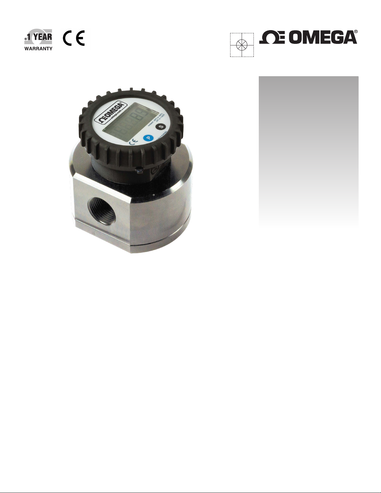
User’s Guide
Shop online at
omega.com
®
e-mail: [email protected]
For latest product manuals:
www.omegamanual.info
FPD3000-D and FPD3000-D-A Series
12mm LC Digital Display
with Analog Output Options for
FPD3000, FPD3200, FPD3300 Series
Page 2

omega.com [email protected]
Servicing North America:
U.S.A.: Omega Engineering, Inc., One Omega Drive, P.O. Box 4047
Stamford, CT 06907-0047 USA
Toll-Free: 1-800-826-6342 (USA & Canada only)
Customer Service: 1-800-622-2378 (USA & Canada only)
Engineering Service: 1-800-872-9436 (USA & Canada only)
Tel: (203) 359-1660 Fax: (203) 359-7700
e-mail: [email protected]
For Other Locations Visit omega.com/worldwide
The information contained in this document is believed to be correct, but OMEGA accepts no liability for any errors it contains, and reserves
the right to alter specifications without notice.
WARNING: These products are not designed for use in, and should not be used for, human applications.
Page 3

index
Product Overview
General Product Functionality
………………………………………………………….
Type FPD3000-D Digital Register
Program Overview
Set-up Functions
Wiring Diagram
Parts Listing
Technical Specifications
………………………………………………………….
………………………………………………………….
………………………………………………………….
………………………………………………………….
………………………………………………………….
Page 4
Page 5
Page 6
Page 7
Page 7
Page 8
Type FPD3000-D-A Digital Register
Program Overview
Set-up Functions
Wiring Diagram
Outputs
Parts Listing
Technical Specifications
List Configuration Settings
Wall Mount Bracket Dimensions
………………………………………………………….
………………………………………………………….
………………………………………………………….
………………………………………………………….
………………………………………………………….
………………………………………………………….
………………………………………………………….
………………………………………………………….
Page 10
Page 11-13
Page 13
Page 14
Page 15
Page 16-17
Page 18
Page 19
3
Page 4
Please read and retain this instruction manual to assist you in the operation of this product.
This Instruction Manual provides a instruction guide on the set-up and programming of the Type FPD3000-D and
FPD3000-D-A, 12mm LCD Digital Register.
PRODUCT OVERVIEW
SYSTEM DESCRIPTION OF THE FPD3000-D and FPD3000-D-A
Functions and features
The flow rate / totalizer model FPD3000 series is a microprocessor driven instrument designed to display flow rate,
total and accumulated total.
This product has been designed with a focus on:
ultra-low power consumption to allow long-life battery powered applications.
The glass reinforced polypropylene housing offers IP65 environmental protection.
Configuration of the unit
The FPD3000 Series has been designed to be implemented in many types of applications. For that reason, a SETUPlevel is available to configure your FPD3000 according to your specific requirements.
It includes several important features, such as K-factors, measurement units etc. All setting are stored in EEPROM
memory and will not be lost in the event of power failure.
Display information
The unit has a large transflective LCD with a range of symbols and digits to display measuring units, status information, trend-indication and key-word messages.
Flow rate and totals can be displayed by using the S button to move through the various options..
A backup of the total and accumulated total in EEPROM memory is made every minute.
OPERATIONALGENERAL
This chapter describes the daily use of the FPD3000–D / -D-A Series Digital Register. This instruction is meant for users / operators.
CONTROL PANEL
The following keys are available:
Functions of the keys
This key is used to program and save new values or settings.
It is also used to gain access to SETUP-level.
This key is used to SELECT the display defaults, ACC.TOTAL, RATE, TOTAL, BATCH
The key is also used in the setup program to scroll through the base levels and options in each level
Pressing both keys simultaneously to CLEAR the value for total and batch then press P
for NO or S for YES to clear the total/batch.
In the setup mode pressing both keys simultaneously whilst in the upper levels of each of
the functions will allow modification of the setting and pressing again will save
4
Page 5
FPD3000-D DIGITAL REGISTER Program Overview
GENERAL
Configuration of the FPD3000-D is done at SETUP-level.
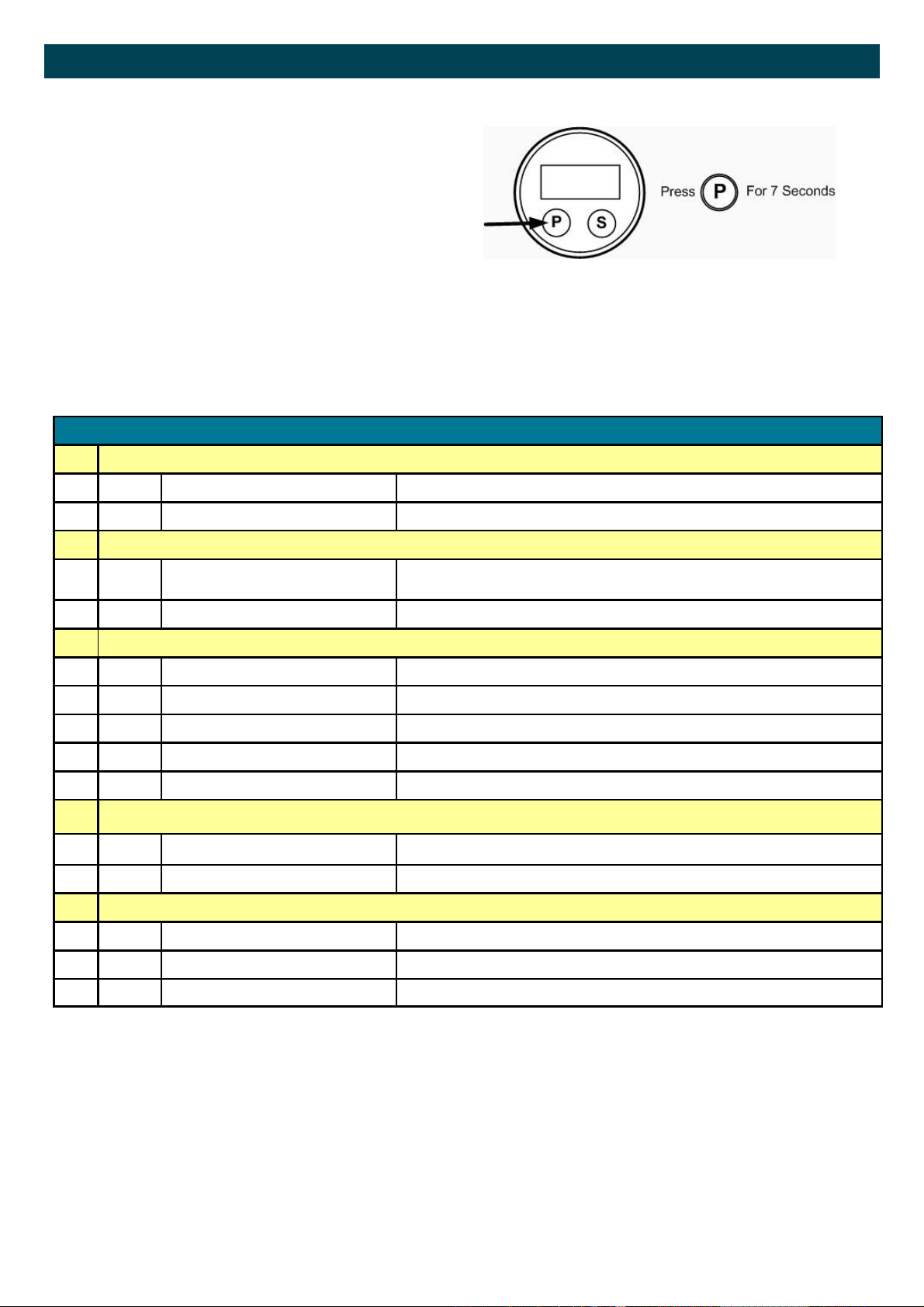
SETUP-level is reached by pressing the PROG/ENTER
key for
7 seconds; at which time, setup will be displayed. In order to return to the operator level, PROG will have to be
pressed for three seconds. Alternatively, if no keys are
pressed for 2 minutes, the unit will exit SETUP automatically.
SETUP can be reached at all times while the register
remains fully operational.
SETUP FUNCTIONS AND VARIABLES
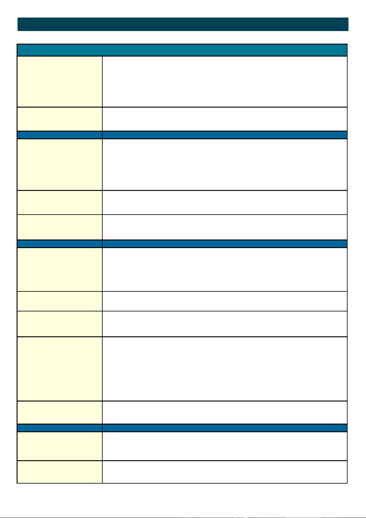
1 TOTAL/BATCH TOTAL
1.1 UNIT L - m3 - UKGAL - USGAL - OILbbl -UKbbl –USbbl
1.2 DECIMALS 0 - 1 - 2 - 3
2 ACCUMULATED TOTAL
2.1 UNIT L - m3 - UKGAL - USGAL - OILbbl -UKbbl –USbbl
2.2 DECIMALS 0 - 1 - 2 - 3
3
RATE
3.1 UNIT L - m3 - UKGAL - USGAL - OILbbl -UKbbl –USbbl
3.2 PERIOD sec - min - hour
3.3 DECIMALS 0 - 1 - 2 - 3
3.4 CALCULATION per 1 - 255 pulses (default 10)
4 METER
3.5 CUT-OFF 0.1 - 999.9 seconds (Default 35)
4 METER SIGNAL Reed Switch Only
4.1 K FACTOR (Pulses per Unit) 0000.000 to 9999.999
5 OTHERS
6.1 TYPE PR
6.2 SOFTWARE VERSION 03.xx.xx
6.3 SERIAL NO. xxxxxxx
5
Page 6
FPD3000-D DIGITAL REGISTER Set-up Functions
SETUP PARAMETERS
TOTAL/BATCH TOTAL
1.1
DECIMALS
1.2
TOTAL ACCUMULATED
2.1
Decimals
2.2
Flow Note The settings for total and flow rate are entirely separate. In this way, different units of measure-
SETUP - 1.1 determines the measurement unit for total and batch total The following units can
be selected:
L - m3 - UKGAL - USGAL - UKbbl - USbbl - OILbbl
Please note that the K-Factor entered in 4.1 should be in pulses per litre and unit adjustment is
done automatically.
The decimal point determines for total and batch total the number of digits following the decimal
point. The following can be selected:
0000000 - 111111.1 - 22222.22 - 3333.333
SETUP - 2.1 determines the measurement unit for accumulated total. The following units can be
selected:
L - m3 - UKGAL - USGAL - UKbbl - USbbl - OILbbl
Please note that the K-Factor entered in 4.1 should be in pulses per litre and unit adjustment is
done automatically.
The decimal point determines for accumulated total the number of digits following the decimal
point. The following can be selected:
0000000 - 111111.1 - 22222.22 - 3333.333
ment can be used for each e.g. cubic meters for total and liters for flow rate.
The display update time for flow rate is one second or more.
RATE
3.1
TIME UNIT
3.2
DECIMALS
3.3
CALCULATION
3.4
CUT-OFF TIME
3.5
K-FACTOR
4.1
The setting allows a K Factor with up to 3 decimal places and 4 whole numbers eg;
SETUP - 21 determines the measurement unit for flow rate.
The following units can be selected:
L - m3 - UKGAL - USGAL - UKbbl - USbbl - OILbbl
Please note that the K-Factor entered in 4.1 should be in pulses per litre and unit adjustment is
done automatically.
The flow rate can be calculated per second (SEC), minute (MIN), hour (HR) or day (DAY).
This setting determines for flow rate the number of digits following the decimal point. The following can be selected:
00000 - 1111.1 - 2222.22 - 3333.333
The flow rate is calculated by measuring the time between a number of pulses, for example 10
pulses. The more pulses the more accurate the flow rate will be. The maximum value is 255
pulses.
Note: the lower the number of pulses, the higher the power consumption of the unit will
be (important for battery powered applications).
Note: for low frequency applications (below 10Hz): do not program more than 10 pulses
else the update time will be very slow.
Note: for high frequency application (above 1kHz) do program a value of 100 or more
pulses.
With this setting, you determine a minimum flow requirement thresh-hold, if during this time
less than XXX-pulses (SETUP 26) are generated, the flow rate will be displayed as zero.
The cut-off time has to be entered in seconds - maximum time is 999 seconds (about 15 minutes).
With the K-factor, the flow meter pulse signals are converted to a flow rate.
The K-factor is based on the number of pulses generated by the flow meter per selected measurement unit (SETUP 1.1), for example per liter. The more accurate the K-factor, the more accurate
the functioning of the system will be.
1234.123
6
Page 7
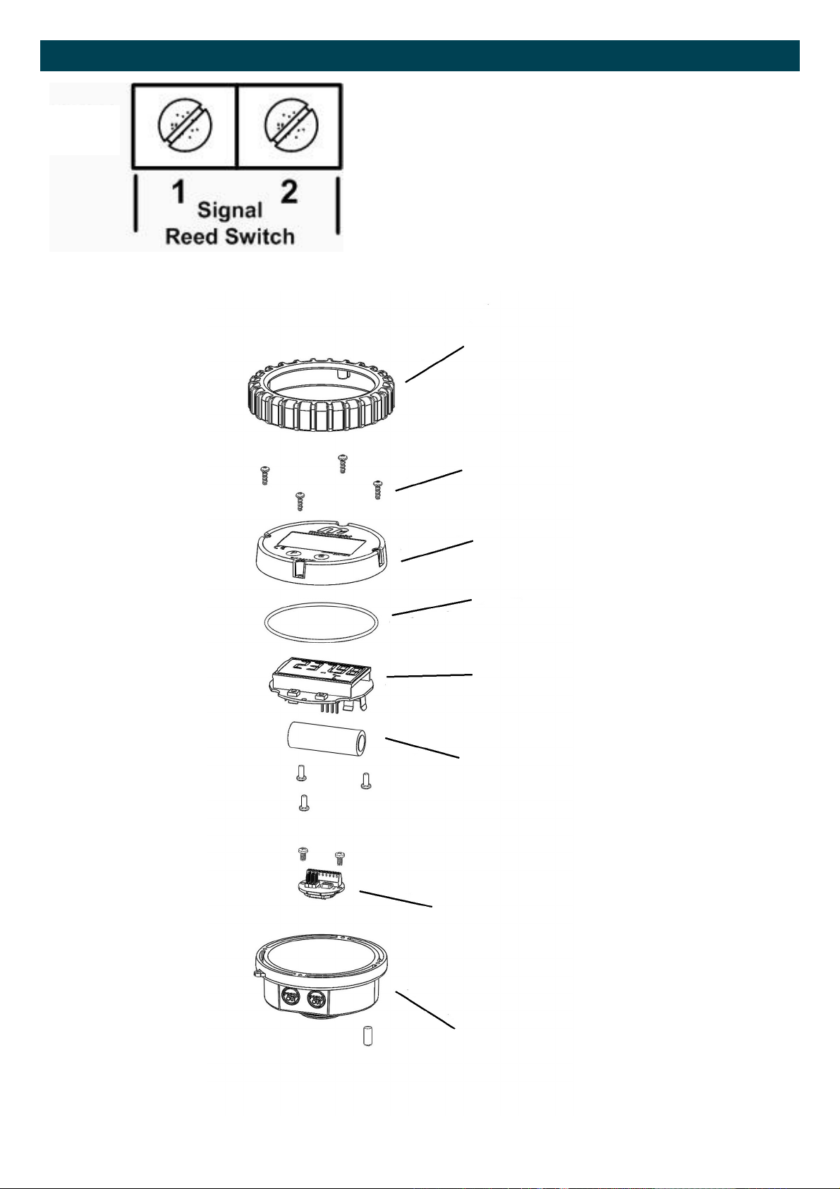
FPD3000-D DIGITAL REGISTER Wiring Diagram and Parts Description
The FPD3000 unit cam only accept a reed switch input, this sensor
has been selected as the most common sensor and requires very
little power with small effect on battery life.
The 2 position terminal block is not polarity conscious so the reed
switch wires can be connected in any order.
Connecting any other sensor type could cause damage to the electronics module
1. Rubber Boot
2. Cover Screws
3. LCD Cover
4. Cover O-Ring
5. LC Display
6. Battery
7. PCB Sensor
8. Polypropylene Housing
7
Page 8
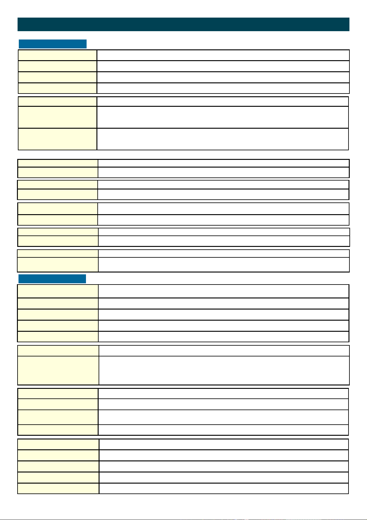
FPD3000-D DIGITAL REGISTER Technical Specifications
GENERAL
Display
Refresh rate Flow Rate: once per second. Total: 8 times/second after key press to one second.
Type High intensity reflective numeric and alphanumeric LCD, UV-resistant.
Digits Seven 12mm (0.47") and seven 8mm (0.31"). Various symbols and measuring units.
Enclosures
General
Control Keys
Aluminium with Polycarbonate window, silicone and EPDM gaskets. UV stabilized and flame retardant material.
Two industrial micro-switch keys. UV-resistant silicone keypad.
Meter mount enclosures
Classification
Cable entry
Operating temperature
Dimensions: 100mm diameter
IP67
Black Anodised
Operational -20°C to +60°C (-4°F to +140°F).
Power supply
Battery powered Lithium battery - life-time depends upon settings - up to 3 years @ 20°C.
Terminal connections
Type: Terminal strip. Wire max. 1mm2
Data protection
Type Backup of all settings and running totals in flash memory.
Environment
Electromagnetic compatibility Compliant ref: EN 61326-1:2006, EN61010-1:2001
INPUT
Total / Batch total /
Accumulated total
Digits 7 digits.
Operator functions
Displayed functions Flow Rate.
Flow Meter
Flow Rate
Units L, m3, US-GAL, UK-GAL, US-bbl, UK-bbl, OIL-bbl.
Decimals 0 - 1 - 2 or 3.
Note total and batch total can be reset to zero.
Total (can be reset to zero by the operator).
Batch total (can be reset to zero by the operator).
Accumulated total (non resettable)
Type reed-switch
Frequency Total: minimum 0 Hz - maximum 120 Hz for total
Flow Rate: 0.01 Hz – maximum 120Hz.
K-Factor 0000.001 - 9,999.999 pulses per unit of measure
Digits 7 digits.
Units L, m3, US-GAL, UK-GAL, US-bbl, UK-bbl, OIL-bbl.
Decimals 0 - 1 - 2 or 3.
Time units /sec - /min - /hr .
8
Page 9

NOTES
9
Page 10
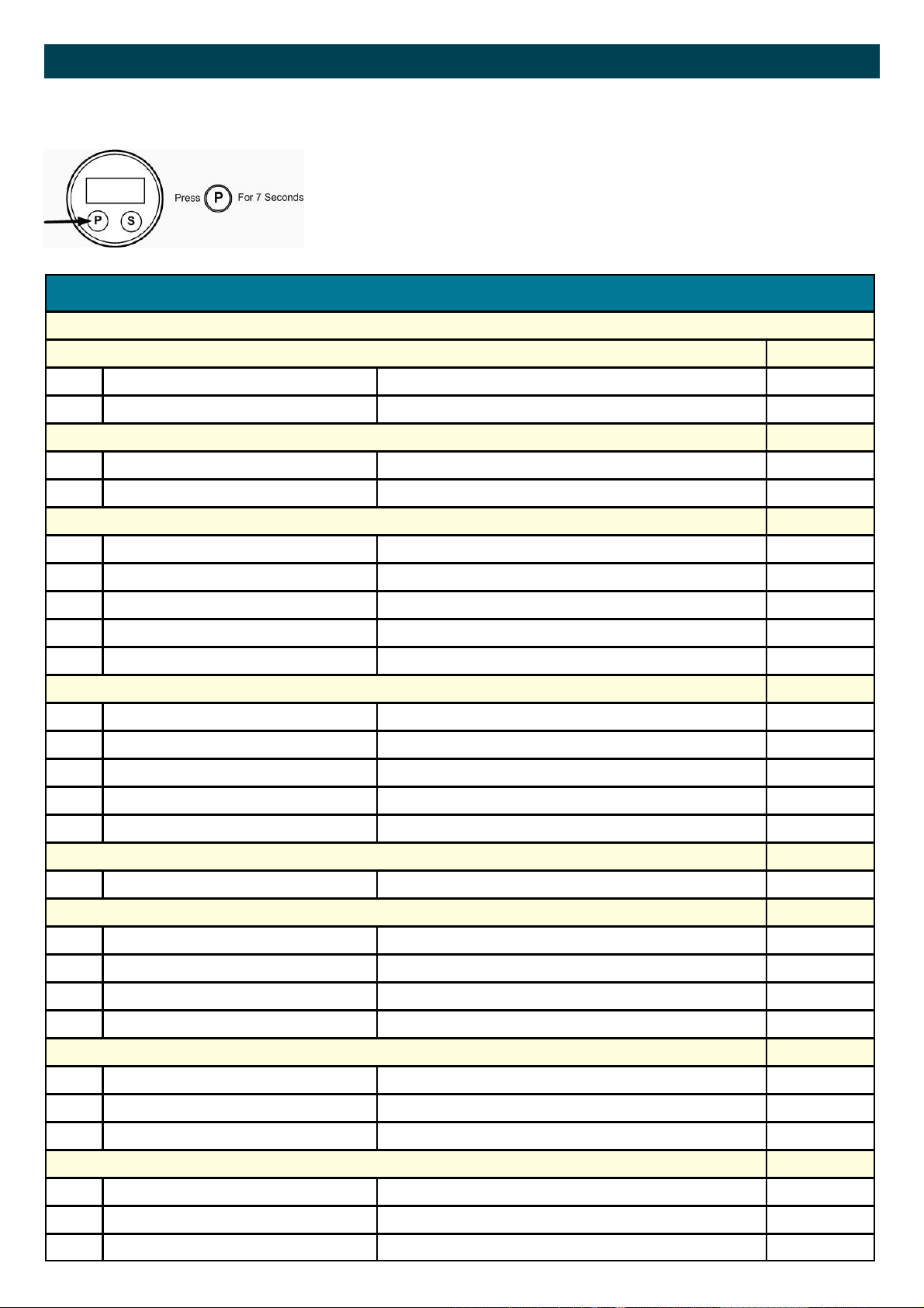
FPD3000-D-A DIGITAL REGISTER Program Overview
PROGRAMMING SETUP-LEVEL
GENERAL
Configuration of the FPD3000-D-A is done at SETUP-level. SETUP-level is
reached by pressing the PROG/ENTER key for 7 seconds; at which time, setup
will be displayed. In order to return to the operator level, PROG will have to be
pressed for three seconds. Alternatively, if no keys are pressed for 2 minutes,
the unit will exit SETUP automatically.
SETUP can be reached at all times while the register remains fully operational.
SETUP FUNCTIONS AND VARIABLES DRA
OPERATE / RUN TIME VARIABLES
TOTAL / BATCH TOTAL DEFAULT
11 UNIT
12 DECIMALS 0 - 1 - 2 – 3 0
L, m3, US-GAL, UK-GAL, US-bbl, UK-bbl, OIL-bbl.
L
ACCUMULATED TOTAL DEFAULT
21 UNIT
22 DECIMALS 0 - 1 - 2 – 3 0
L, m3, US-GAL, UK-GAL, US-bbl, UK-bbl, OIL-bbl.
L
FLOWRATE DEFAULT
31 UNIT
32 TIME UNIT sec - min - hour min
33 DECIMALS 0 - 1 - 2 – 3 0
34 CALCULATION per 1 – 255 pulses 10
35 CUT-OFF 0.1 – 999.9 seconds 30.0
L, m3, US-GAL, UK-GAL, US-bbl, UK-bbl, OIL-bbl.
L
ALARM DEFAULT
41 FLOW ALARM operate - hidden - off off
42 FLOW ZERO on - off on
43 ALARM LOW 0000.000 unit/time unit 0
44 ALARM HIGH 0000.000 unit/time unit 99999
45 DELAY ALARM 0… 99 seconds 0
FLOWMETER DEFAULT
51 K-FACTOR 0000.001 - 9999.999 pulses / unit of measure 1.000
ANALOG OUTPUT DEFAULT
61 LOW FLOW 0000.000 - 9,999,999 unit/time unit 0
62 HIGH FLOW 0000.000 - 9,999,999 unit/time unit 99999
63 LOW CALIB - 4mA 0 - 9999 631
64 HIGH CALIB - 20mA 0 - 9999 3200
PULSE OUTPUT DEFAULT
71 DECIMALS 0 - 1 - 2 – 3 0
72 PULSE WIDTH 0.005 - 1.000 sec 0
73 PULSE PER X,XXX,XXX quantity 1000
OTHERS DEFAULT
81 MODEL / TYPE DRA -
82 SOFTWARE VERSION xx.xx.xx -
83 SERIAL NO. xxxxxxx -
10
Page 11
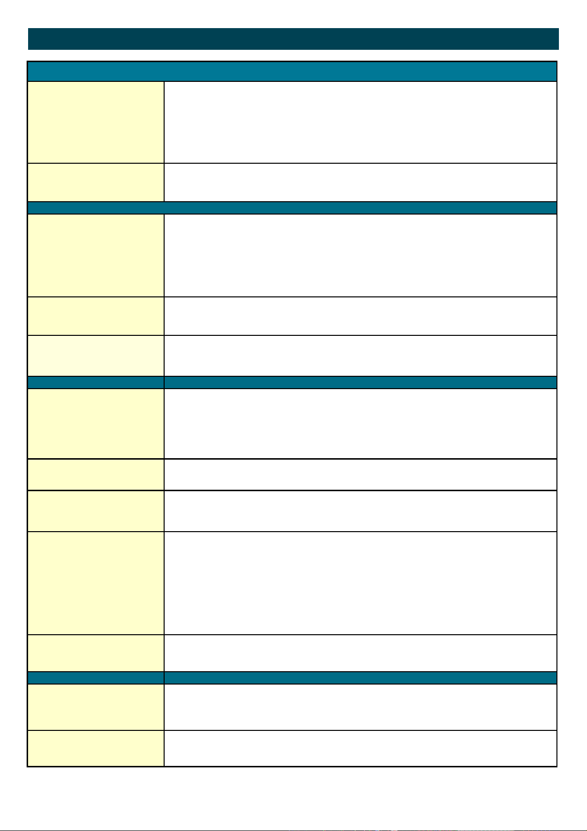
FPD3000-D-A DIGITAL REGISTER Set-up Functions
SETUP PARAMETERS
TOTAL/BATCH TOTAL
1.1
DECIMALS
1.2
TOTAL
ACCUMULATED
2.1
Decimals
2.2
Flow Note The settings for total and flow rate are entirely separate. In this way, different units of measure-
SETUP - 1.1 determines the measurement unit for total and batch total The following units can
be selected:
L - m3 - UKGAL - USGAL - UKbbl - USbbl - OILbbl
Please note that the K-Factor entered in 5.1 should be in pulses per litre and unit adjustment is
done automatically.
The decimal point determines for total and batch total the number of digits following the decimal
point. The following can be selected:
0000000 - 111111.1 - 22222.22 - 3333.333
SETUP - 2.1 determines the measurement unit for accumulated total. The following units can be
selected:
L - m3 - UKGAL - USGAL - UKbbl - USbbl - OILbbl
Please note that the K-Factor entered in 5.1 should be in pulses per litre and unit adjustment is
done automatically.
The decimal point determines for accumulated total the number of digits following the decimal
point. The following can be selected:
0000000 - 111111.1 - 22222.22 - 3333.333
ment can be used for each e.g. cubic meters for total and liters for flow rate.
The display update time for flow rate is one second or more.
FLOW RATE
3.1
TIME UNIT
3.2
DECIMALS
3.3
CALCULATION
3.4
CUT-OFF TIME
3.5
FLOW METER
K FACTOR
5.1
SETTING K-FACTOR The setting allows a K Factor with up to 3 decimal places and 4 whole numbers eg;
SETUP - 21 determines the measurement unit for flow rate.
The following units can be selected:
L - m3 - UKGAL - USGAL - UKbbl - USbbl - OILbbl
Please note that the K-Factor entered in 5.1 should be in pulses per litre and unit adjustment is
done automatically.
The flow rate can be calculated per second (SEC), minute (MIN), hour (HR) or day (DAY).
This setting determines for flow rate the number of digits following the decimal point. The following can be selected:
00000 - 1111.1 - 2222.22 - 3333.333
The flow rate is calculated by measuring the time between a number of pulses, for example 10
pulses. The more pulses the more accurate the flow rate will be. The maximum value is 255
pulses.
Note: the lower the number of pulses, the higher the power consumption of the unit will
be (important for battery powered applications).
Note: for low frequency applications (below 10Hz): do not program more than 10 pulses
else the update time will be very slow.
Note: for high frequency application (above 1kHz) do program a value of 100 or more
pulses.
With this setting, you determine a minimum flow requirement thresh-hold, if during this time
less than XXX-pulses (SETUP 26) are generated, the flow rate will be displayed as zero.
The cut-off time has to be entered in seconds - maximum time is 999 seconds (about 15 minutes).
With the K-factor, the flow meter pulse signals are converted to a flow rate.
The K-factor is based on the number of pulses generated by the flow meter per selected measurement unit (SETUP 1.1), for example per liter. The more accurate the K-factor, the more accurate
the functioning of the system will be.
1234.123
11
Page 12
FPD3000-D-A DIGITAL REGISTER Set-up Functions
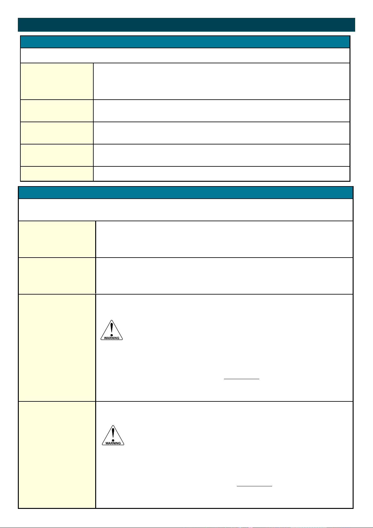
4 - ALARM
With these settings, it is determined how the flow rate will be monitored and the functionality of the transistor outputs be determined.
ALARM
4.1
ALARM VALUE
ZERO
4.2
ALARM VALUE
LOW
4.3
ALARM VALUE
HIGH
4.4
DELAY TIME ALARM
4.5
Setting the function of the Alarm
The following settings can be selected:
Off: Function disabled.
Operate: Full function of the low flow alarm.
Hidden: Does not display alarms on LCD.
The Zero alarm is set with this setting. An alarm will be generated as long as there is no flow rate.
Select Off to disable
The low alarm is set with this setting. An alarm will be generated as long as the flow rate is lower
than this.
With value 0.0 this function is disabled.
The high alarm is set with this setting. An alarm will be generated as long as the flow rate is higher
than this.
With value 0.0 this function is disabled.
This function allows a delay period before the alarm is activated 0—99 seconds.
6 - ANALOG OUTPUT
A linear analog (0)4-20mA signal is generated according to the flow rate with a 10 bits resolution. The settings for flow rate
(SETUP - 2) influence the analog output directly.
The relationship between rate and analog output is set with the following functions:
MINIMUM FLOWRATE
6.1
MAXIMUM FLOWRATE
6.2
TUNE MIN / 4MA
6.3
TUNE MAX / 20MA
6.4
Enter here the flowrate at which the output should generate the minimum signal (0/4mA or 0V) - in
most applications at flow rate "zero".
The number of decimals displayed depend upon SETUP 23.
The time and measuring units (L/min for example) are dependant upon SETUP 21 and 22 but are
not displayed.
Enter here the flow rate at which the output should generate the maximum signal (20mA or 10V) in most applications at maximum flow.
The number of decimals displayed depend upon SETUP 23.
The time and measuring units (L/min for example) are dependant upon SETUP 21 and 22 but can
not be displayed.
The initial minimum analog output value is 4mA . However, this value might differ slightly due to
external influences such as temperature for example. The 4mA value can be tuned precisely with
this setting.
Before tuning the signal, be sure that the analog signal is not being used for any
application!
After pressing PROG, the current will be about 4mA The current can be increased / decreased with
incrementing or decrementing the numbers and is directly active. Press ENTER to store the new
value.
Remark: the analog output value can be programmed “up-side-down” if desired, so 20mA at mini-
mum flowrate for example!
The initial maximum analog output value is 20mA. However, this value might differ slightly due to
external influences such as temperature for example. The 20mA value can be tuned precisely with
this setting.
Before tuning the signal, be sure that the analog signal is not being used for any
application!
After pressing PROG, the current will be about 20mA. The current can be increased / decreased
with incrementing or decrementing the numbers and is directly active. Press ENTER to store the
new value.
Remark: the analog output value can be programmed “up-side-down” if desired, so 4mA at maxi-
mum flow rate for example!
12
Page 13
FPD3000-D-A DIGITAL REGISTER Set-up Functions
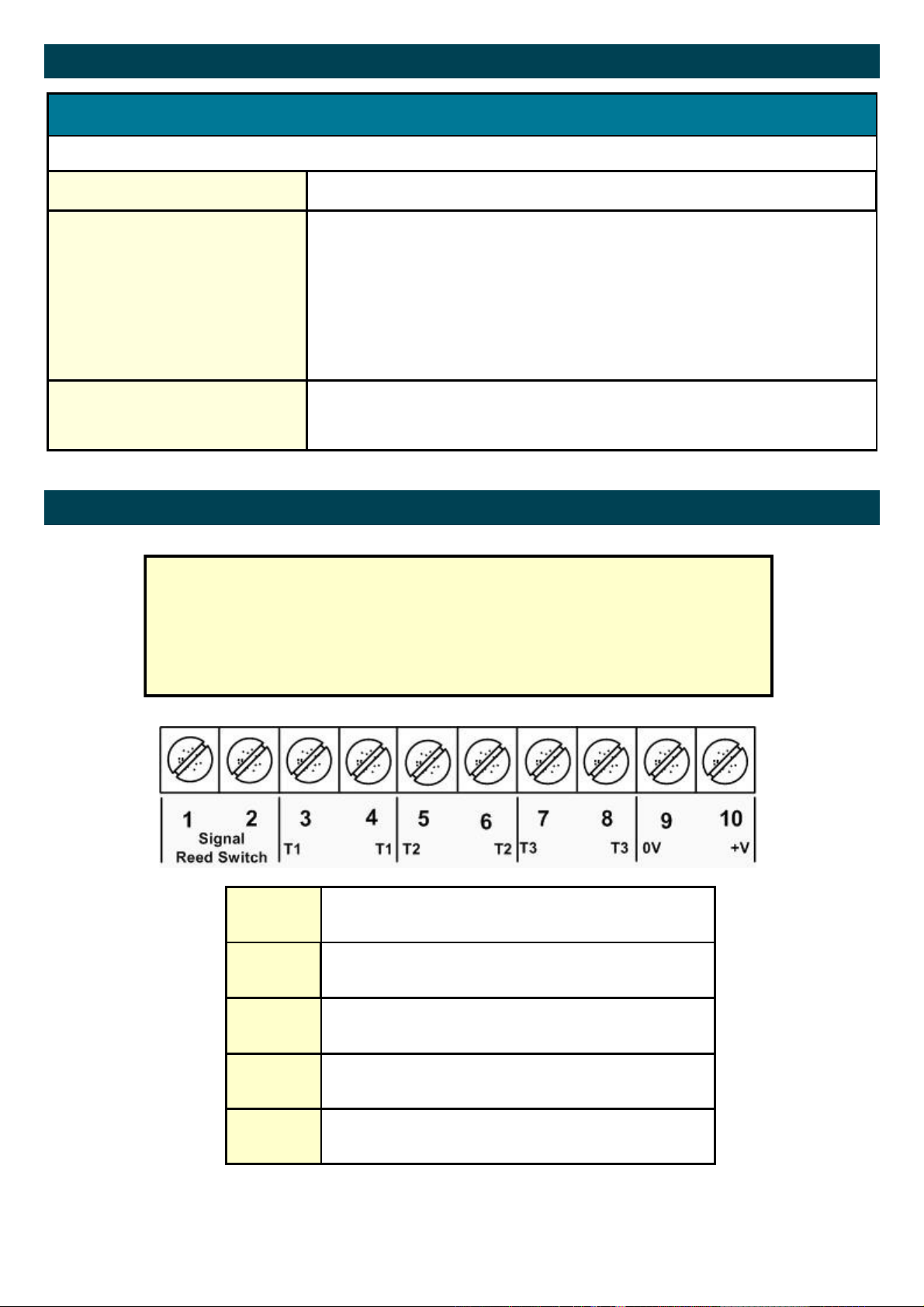
7 - PULSE OUTPUT
One transistor output is available as scaled pulse output according to the accumulated total.
DECIMALS
7.1
WIDTH OF PULSE
7.2
PULSE PER
7.3
Sets the decimals for the pulses per 7.3
The pulse width determines the time that the transistor will be switched; in other words
the pulse length. The minimum time between the pulses is as long as the selected period
time.
Pulse widths are between 5 m sec to 1 sec at 5 m sec this is a frequency of 100Hz
Note: If the frequency should go out of range - when the flow rate increases for
example - an internal buffer will be used to "store the missed pulses": As soon as
the flow rate reduces again, the buffer will be "emptied".
It might be that pulses will be missed due to a buffer-overflow, so it is advised to
program this setting within it's range.
According to the measurement unit settings for total, a pulse will be generated every Xquantity. Enter this quantity here while taking the displayed decimal position and measuring unit into account. i.e. set to 00000.10 = 10 pulses per unit of measure selected
Type DRA DIGITAL REGISTER Wiring Diagram
The FPD3000-D-A unit can only accept a reed switch input, this sensor has been selected as the most common sensor and requires very little power with small effect on battery life.
The reed switch is not polarity conscious so the reed switch wires can be connected in
any order to pins 1 and 2
1
2
3 T1
4 T1
5 T2
6 T2
7 T3
8 T3
9
10
Reed Switch Sensor Input
Reed Switch Sensor Input
Pulse Output - 0V
Pulse Output +V
Low Alarm 0V
Low Alarm +V
High Alarm 0V
High Alarm +V
Analog Output & Power Supply 0V
Analog Output & Power Supply +V
13
Page 14
9
10
FPD3000-D-A DIGITAL REGISTER Outputs
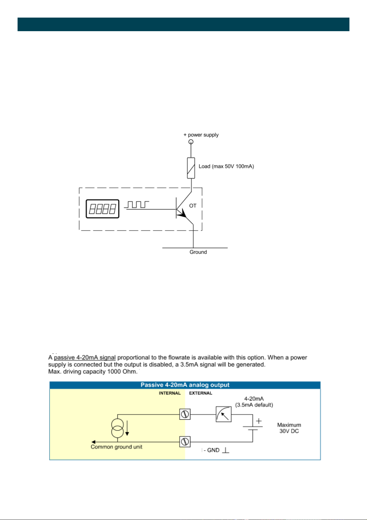
Pulse Output
Example for scaled 1 pulse per litre the output must be programmed as follows:
In menu 7.1 set 2222.22
In menu 7.2 set 10 or more (10mS or more if needed)
In menu 7.3 set 1.00
Example Pulse/Alarm Output Setup
Passive 4-20mA setup
14
Page 15
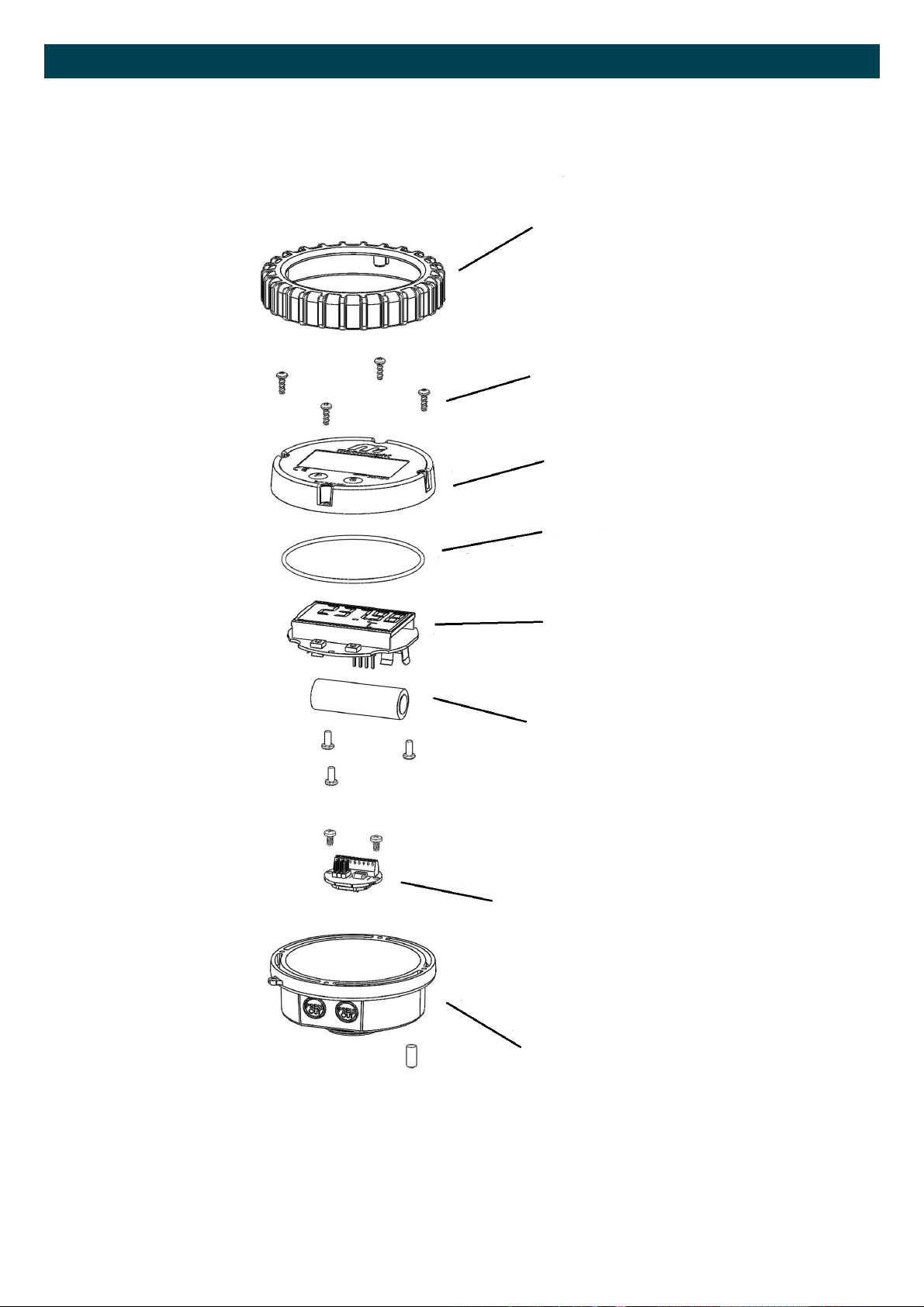
FPD3000-D-A DIGITAL REGISTER Parts Description
1. Rubber Boot
2. Cover Screws
3. LCD Cover
4. Cover O-Ring
5. LC Display
6. Battery
7. PCB Sensor
8. Polypropylene Housing
15
Page 16
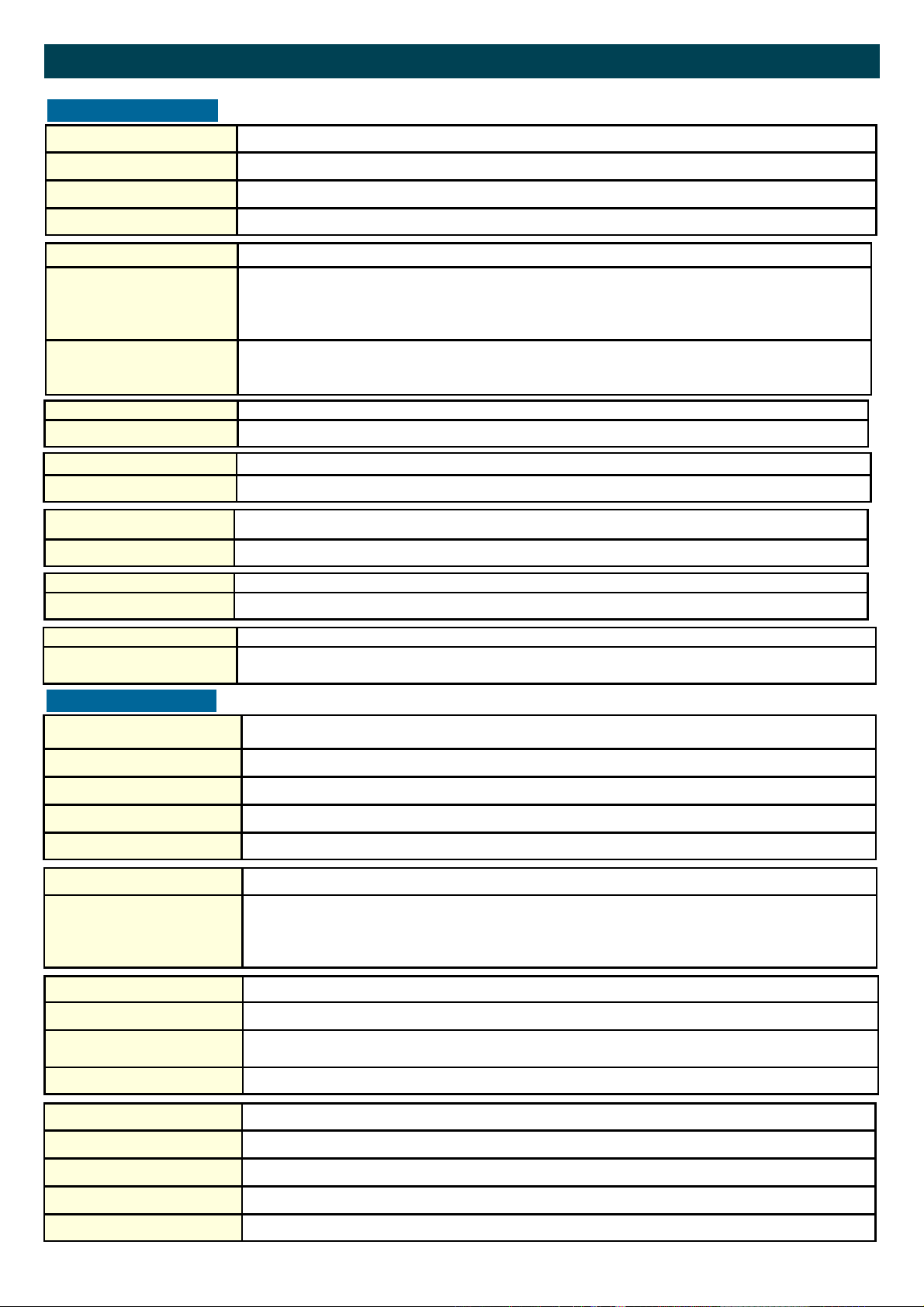
FPD3000-D-A DIGITAL REGISTER Technical Specifications
GENERAL
Display
Refresh rate Flow Rate: once per second. Total: 8 times/second after key press to one second.
Type High intensity reflective numeric and alphanumeric LCD, UV-resistant.
Digits Seven 12mm (0.47") and seven 8mm (0.31"). Various symbols and measuring units.
Enclosures
General
Control Keys
Painting
Meter mount enclosures
Classification
Cable entry
Operating temperature
Aluminium with Polycarbonate window, silicone and EPDM gaskets. UV stabilized and flame retardant material.
Two industrial micro-switch keys. UV-resistant silicone keypad.
?????
Dimensions: 100mm diameter
IP67
Black Anodised
Operational -20°C to +60°C (-4°F to +140°F).
Power supply
Battery powered Lithium battery - life-time depends upon settings - up to 3 years @ 20°C.
Terminal connections
Type: Terminal strip. Wire max. 1mm2
Data protection
Type Backup of all settings and running totals in flash memory.
Environment
Electromagnetic compatibility Compliant ref: EN 61326-1:2006, EN61010-1:2001
INPUT
Total / Batch total /
Accumulated total
Digits 7 digits.
Operator functions
Displayed functions Flow Rate.
Flow Meter
Flow Rate
Units L, m3, US-GAL, UK-GAL, US-bbl, UK-bbl, OIL-bbl.
Decimals 0 - 1 - 2 or 3.
Note total and batch total can be reset to zero.
Total (can be reset to zero by the operator).
Batch total (can be reset to zero by the operator).
Accumulated total (non resettable)
Type reed-switch
Frequency Total: minimum 0 Hz - maximum 120 Hz for total
Flow Rate: 0.01 Hz – maximum 120Hz.
K-Factor 0000.001 - 9,999.999 pulses per unit of measure
Digits 7 digits.
Units L, m3, US-GAL, UK-GAL, US-bbl, UK-bbl, OIL-bbl.
Decimals 0 - 1 - 2 or 3.
Time units /sec - /min - /hr .
16
Page 17
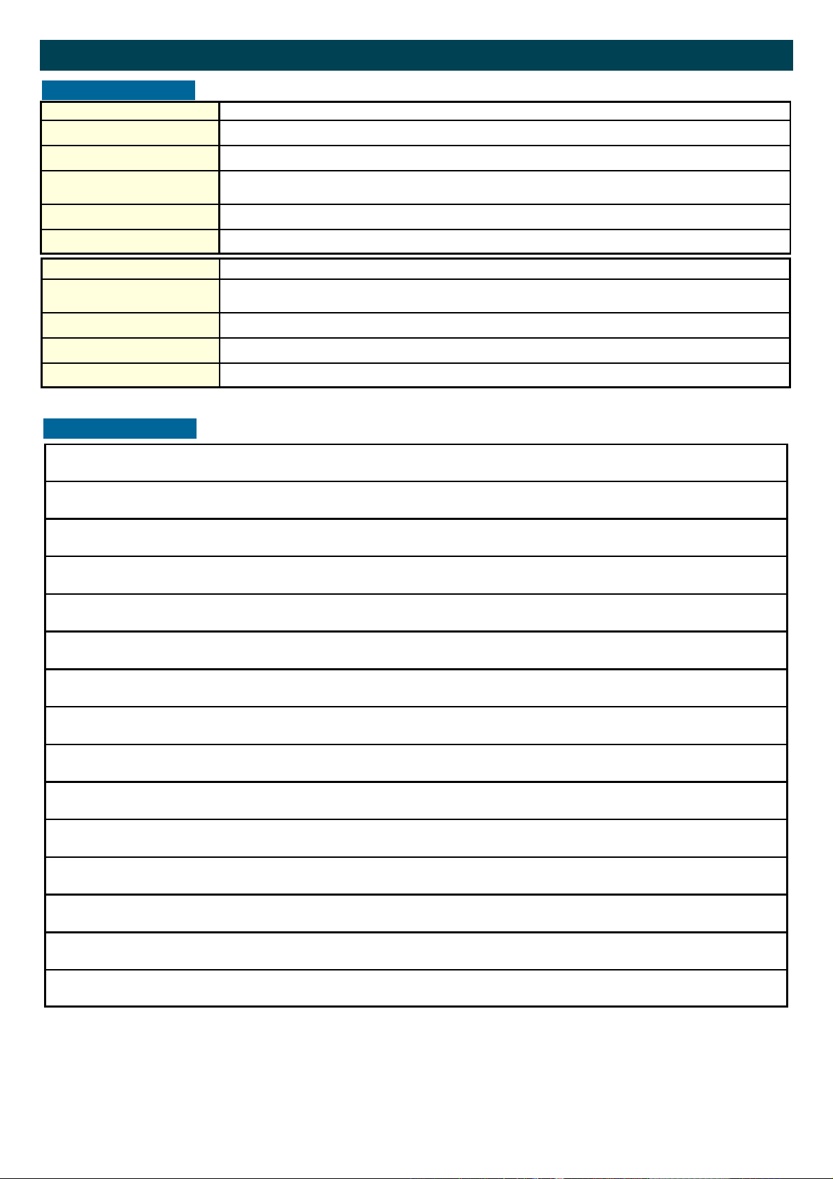
FPD3000-D-A DIGITAL REGISTER Technical Specifications
OUTPUTS
Analog output
Function transmitting flow rate.
Type Passive 4-20mA output - output loop powered.
Accuracy 10 bit. Update 8 times a second.
Software function to calibrate the 4.00mA and 20.00mA levels precisely within set-up.
Minimum operating voltage 8V DC
Power supply 18-30V DC
Switch outputs
Function One scaled pulse output - transmitting accumulated total.
One high flowrate and one low flowrate alarm output.
Pulse output Max. frequency 100Hz. Pulse length user definable between 5msec up to 1 second.
Type OT Passive transistor output - isolated. Load max. 50V DC - 100mA.
Isolation 100V DC maximum.
NOTES
17
Page 18
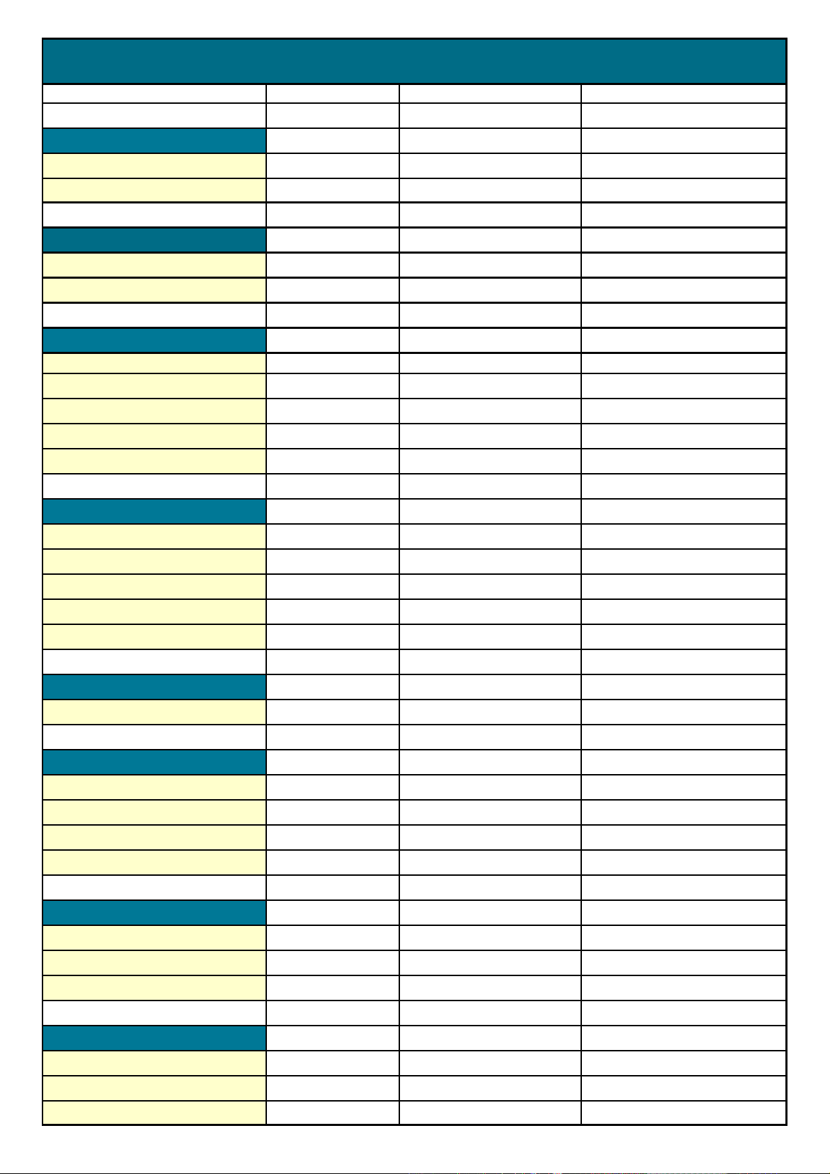
List of configuration settings
SETTING DEFAULT DATE : DATE :
1 - TOTAL
11 unit
12 decimals
2- ACCMULATED TOTAL
21 unit
22 decimals
3 - FLOWRATE
31 unit
32 time unit
33 decimals
34 calculation / pulses
35 cut-off time
L
0000000
L
0000000
L
/min
0000000
010
30.0 sec.
Enter your settings here
4 - Alarm
41 alarm
42 flow zero
43 alarm low
44 alarm high
45 delay alarm
5 - FLOWMETER
51 k factor
6 - ANALOG OUTPUT
61 4 mA
62 20 mA
63 max. tune min 4 mA
64 tune max 20 mA
7 - PULSE OUTPUT
71 decimal
71 impulse width
72 pulse per
disabled
on
0
9999
0
1.000
0
99999
0
0
1000
8 - OTHERS
81 model
82 software version
83 serial number
DRA
30.05.01
18
Page 19
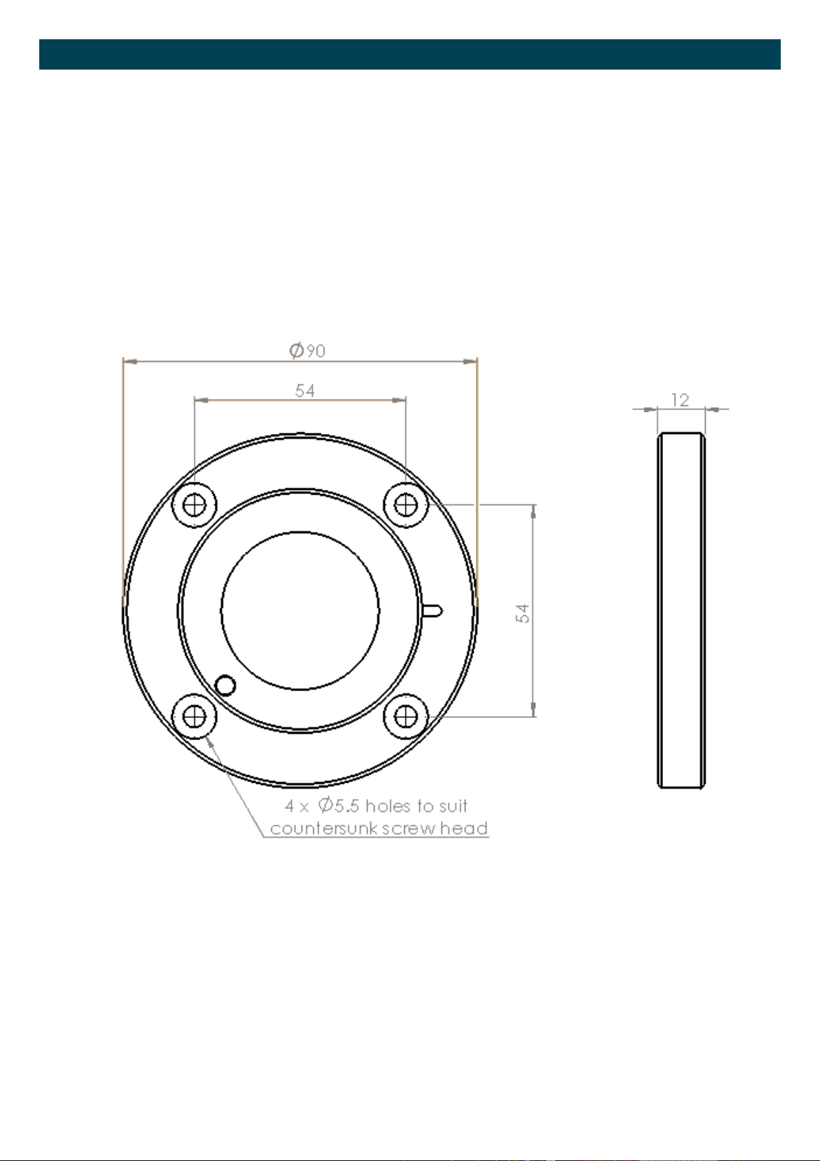
Wall Mount Bracket
The FPD3000 series is available with a Wall Mount Bracket option for applications requiring remote mount display.
Both the models -D and –D-A are available with this option.
Following is a dimensional drawing for the wall mount bracket.
19
Page 20

WARRANTY/DISCLAIMER
OMEGA ENGINEERING, INC. warrants this unit to be free of defects in materials and workmanship for a
period of 13 months from date of purchase. OMEGA’s WARRANTY adds an additional one (1) month
grace period to the normal one (1) year product warranty to cover handling and shipping time. This
ensures that OMEGA’s customers receive maximum coverage on each product.
If the unit malfunctions, it must be returned to the factory for evaluation. OMEGA’s Customer Service
Department will issue an Authorized Return (AR) number immediately upon phone or written request.
Upon examination by OMEGA, if the unit is found to be defective, it will be repaired or replaced at no
charge. OMEGA’s WARRANTY does not apply to defects resulting from any action of the purchaser,
including but not limited to mishandling, improper interfacing, operation outside of design limits,
improper repair, or unauthorized modification. This WARRANTY is VOID if the unit shows evidence of
having been tampered with or shows evidence of having been damaged as a result of excessive corrosion;
or current, heat, moisture or vibration; improper specification; misapplication; misuse or other operating
conditions outside of OMEGA’s control. Components in which wear is not warranted, include but are not
limited to contact points, fuses, and triacs.
OMEGA is pleased to offer suggestions on the use of its various products. However,
OMEGA neither assumes responsibility for any omissions or errors nor assumes liability for
any damages that result from the use of its products in accordance with information provided
by OMEGA, either verbal or written. OMEGA warrants only that the parts manufactured by the
company will be as specified and free of defects. OMEGA MAKES NO OTHER WARRANTIES OR
REPRESENTATIONS OF ANY KIND WHATSOEVER, EXPRESSED OR IMPLIED, EXCEPT THAT OF
TITLE, AND ALL IMPLIED WARRANTIES INCLUDING ANY WARRANTY OF MERCHANTABILITY
AND FITNESS FOR A PARTICULAR PURPOSE ARE HEREBY DISCLAIMED. LIMITATION OF
LIABILITY: The remedies of purchaser set forth herein are exclusive, and the total liability of
OMEGA with respect to this order, whether based on contract, warranty, negligence,
indemnification, strict liability or otherwise, shall not exceed the purchase price of the
component upon which liability is based. In no event shall OMEGA be liable for
consequential, incidental or special damages.
CONDITIONS: Equipment sold by OMEGA is not intended to be used, nor shall it be used: (1) as a “Basic
Component” under 10 CFR 21 (NRC), used in or with any nuclear installation or activity; or (2) in medical
applications or used on humans. Should any Product(s) be used in or with any nuclear installation or
activity, medical application, used on humans, or misused in any way, OMEGA assumes no responsibility
as set forth in our basic WARRANTY/DISCLAIMER language, and, additionally, purchaser will indemnify
OMEGA and hold OMEGA harmless from any liability or damage whatsoever arising out of the use of the
Product(s) in such a manner.
RETURN REQUESTS/INQUIRIES
Direct all warranty and repair requests/inquiries to the OMEGA Customer Service Department.
BEFORE RETURNING ANY PRODUCT(S) TO OMEGA, PURCHASER MUST OBTAIN AN AUTHORIZED
RETURN (AR) NUMBER FROM OMEGA’S CUSTOMER SERVICE DEPARTMENT (IN ORDER TO AVOID
PROCESSING DELAYS). The assigned AR number should then be marked on the outside of the return
package and on any correspondence.
The purchaser is responsible for shipping charges, freight, insurance and proper packaging to prevent
breakage in transit.
FOR WARRANTY RETURNS, please have the
following information available BEFORE
contacting OMEGA:
1. Purchase Order number under which the product
was PURCHASED,
2. Model and serial number of the product under
warranty, and
3. Repair instructions and/or specific problems
relative to the product.
OMEGA’s policy is to make running changes, not model changes, whenever an improvement is possible. This affords
our customers the latest in technology and engineering.
OMEGA is a registered trademark of OMEGA ENGINEERING, INC.
© Copyright 2013 OMEGA ENGINEERING, INC. All rights reserved. This document may not be copied, photocopied,
reproduced, translated, or reduced to any electronic medium or machine-readable form, in whole or in part, without the
prior written consent of OMEGA ENGINEERING, INC.
FOR NON-WARRANTY REPAIRS,
for current repair charges. Have the following
information available BEFORE contacting OMEGA:
1. Purchase Order number to cover the COST
of the repair,
2. Model and serial number of the product, and
3. Repair instructions and/or specific problems
relative to the product.
consult OMEGA
Page 21

Where Do I Find Everything I Need for
Process Measurement and Control?
OMEGA…Of Course!
Shop online at omega.com
TEMPERATURE
MU
Thermocouple, RTD & Thermistor Probes, Connectors, Panels & Assemblies
MU
Wire: Thermocouple, RTD & Thermistor
MU
Calibrators & Ice Point References
MU
Recorders, Controllers & Process Monitors
MU
Infrared Pyrometers
PRESSURE, STRAIN AND FORCE
MU
Transducers & Strain Gages
MU
Load Cells & Pressure Gages
MU
Displacement Transducers
MU
Instrumentation & Accessories
FLOW/LEVEL
MU
Rotameters, Gas Mass Flowmeters & Flow Computers
MU
Air Velocity Indicators
MU
Turbine/Paddlewheel Systems
MU
Totalizers & Batch Controllers
SM
pH/CONDUCTIVITY
MU
pH Electrodes, Testers & Accessories
MU
Benchtop/Laboratory Meters
MU
Controllers, Calibrators, Simulators & Pumps
MU
Industrial pH & Conductivity Equipment
DATA ACQUISITION
MU
Data Acquisition & Engineering Software
MU
Communications-Based Acquisition Systems
MU
Plug-in Cards for Apple, IBM & Compatibles
MU
Data Logging Systems
MU
Recorders, Printers & Plotters
HEATERS
MU
Heating Cable
MU
Cartridge & Strip Heaters
MU
Immersion & Band Heaters
MU
Flexible Heaters
MU
Laboratory Heaters
ENVIRONMENTAL
MONITORING AND CONTROL
MU
Metering & Control Instrumentation
MU
Refractometers
MU
Pumps & Tubing
MU
Air, Soil & Water Monitors
MU
Industrial Water & Wastewater Treatment
MU
pH, Conductivity & Dissolved Oxygen Instruments
M-5427/0714
 Loading...