

Page 1

User’s Guide
Shop online at
omega.com
e-mail: [email protected]
For latest product manuals:
www.omegamanual.info
SM
FPB SERIES
Paddlewheel Flowmeter
Page 2

omega.com [email protected]
Servicing North America:
U.S.A. Omega Engineering, Inc.
Headquarters: Toll-Free: 1-800-826-6342 (USA & Canada only)
Customer Service: 1-800-622-2378 (USA & Canada only)
Engineering Service: 1-800-872-9436 (USA & Canada only)
Tel: (203) 359-1660 Fax: (203) 359-7700
e-mail: [email protected]
For Other Locations Visit omega.com/worldwide
The information contained in this document is believed to be correct, but OMEGA accepts no liability for any errors it contains, and reserves
the right to alter specifications without notice.
Page 3
Omega FPB Series Paddlewheel Flowmeter
SAFETY INSTRUCTIONS
1. Depressurize and vent system prior to installation or removal.
2. Conrmchemicalcompatibilitybeforeuse.
3. Donotexceedmaximumtemperature/pressurespecications.
4. Wearsafetygogglesorfaceshieldduringinstallation/service.
5. Donotalterproductconstruction.
6. Ifthisequipmentisusedinamannernotspeciedbythemanufacturer,theprotectionprovided
bytheequipmentmaybeimpaired.
7. This device is not approved for use or installation in hazardous locations.
Description
TheOmegaFPBPaddlewheelFlowmeterSeriesofferslowow,lowpowerandhighresolutionwithvariousoutputoptionssuchas
aVolumetricPulse,PulseDivider,FlowSwitch,or4to20mA.Thisunitcanbeconguredon-sitedirectlythroughthebuilt-inuser
interface.
• The4to20mAmodelprovidesablindcurrentloopoutput.
• TheMultimodelusesasinglerelay(mechanicalorsolidstate)andhasthreeselectableoperatingmodes:
• DividerModescalesthepaddlewheelfrequencydowntoaccommodatelowfrequencyinputdevices.
• TotalModeoutputsonepulseperasetvolumeofuid.
• FlowSwitchModeusesasinglerelayforHiorLoalarmoperation.
AsmallLCDenablestheFPBtobeprogrammedwithoutanyexternalequipment.Duringnormaloperationthedisplayisnotvisible.
Specications
General
Wetted Materials
Series Sensor Body Rotor Pin O-ring
FPB1X1,1X2 glass-lledPP PVDF,Black Titanium FPM
FPB1X3 PVDF,Natural PVDF,Natural PVDF,Natural FPM
Case: PBT,yellow
InsideCover: Valox,black
WiringPorts: ½in.NPTthreads;liquid-tight
connectoracceptscables7to
10mmOD(0.275in.to0.394in.)
Power Requirements
Multi:
withDry-ContactRelay: 24VDCnominal,±10%,regulated
30mAmax.current
withSolid-StateRelay: 5to24VDCnominal,±10%,regulated
30mAmax.current
4to20mA: 400mVmax.ripplevoltage
30mAmax.current
ReversePolarityandShortCircuitProtected:Upto40V,1hour
Over-VoltageProtection: >40VDCover1hour
Paddlewheel Sensor Performance Specications
PipeSizeRange: DN15toDN200(½in.to8in.)
Min.ReynoldsNumber: 4500
PaddlewheelFrequency: 49Hzperm/snominal
(15Hzperft/snominal)
OperatingRange: 0.1m/sto6m/s(0.3ft/sto20ft/s)
Linearity: ±1%ofmax.range@25°C(77°F)
Repeatability: ±0.5%ofmax.range@25°C(77°F)
Electronics Performance Specications
InputFrequencyRange: 1to1000Hz
SystemResponse: 100msupdateratenominal
Output Specications
SignalAveraging: Programmable0to100seconds
SensitivityResponse: Programmable0to9scale
Pulse Divider/Total Pulse Output
PulseDividerSetting: 1.0000to99999
Maximumpulserate:300Hz
Maximumpulsewidth:50ms
Flow Switch Output
RelayModes: Low,High
TimeDelay: 0.0to6400.0seconds
Hysteresis: AdjustableinEngineeringUnits
Relay Specications
DryContactSPDT: 5A@30VDC,5A@250VAC
Solid-StateRelay: 100mA@40VDC,70mA@33VAC
Current output (Passive 4 to 20 mA)
LoopAccuracy: ±32µA(@25°C@24VDC)
LoopResolution: 5µA
Temp.Drift: ±1µAper°Cmax.
PowerSupplyRejection: ±1uAperV
MaximumCableLength: 305m(1,000ft)
MaxLoopResistance: 600Ω@24VDC,1KΩ@32VDC
Standards & Approvals
• CE
• ManufacturedunderISO9001,ISO14001
Environmental Requirements
EnclosureRating: NEMA4X/IP65
StorageTemperature: -10to75°C(14to167°F)
AmbientTemperature: 0to65°C(32to150°F)
RelativeHumidity: 0to90%RH,non-condensing
Altitude: 2000m(6,562ft)
PollutionDegree: 2
1Omega FPB Series Flowmeter
Page 4
-18 4
27
49
71 93
°C
psi
bar
115
3
6
8
11
14
bar
-18 4
27
49
71 93
°C
115
PVDF
Polypropylene
Fluid Conditions
Reducer
15 x I.D. 5 x I.D.
20 x I.D. 5 x I.D.
90° Elbow
40 x I.D. 5 x I.D.
2 x 90° Elbow
3 dimensions
25 x I.D. 5 x I.D.
2 x 90° Elbow
50 x I.D. 5 x I.D.
Pump/Valve
+
GF
+
+GF+
+
GF
+
+
GF
+
+GF+
OKOK OK
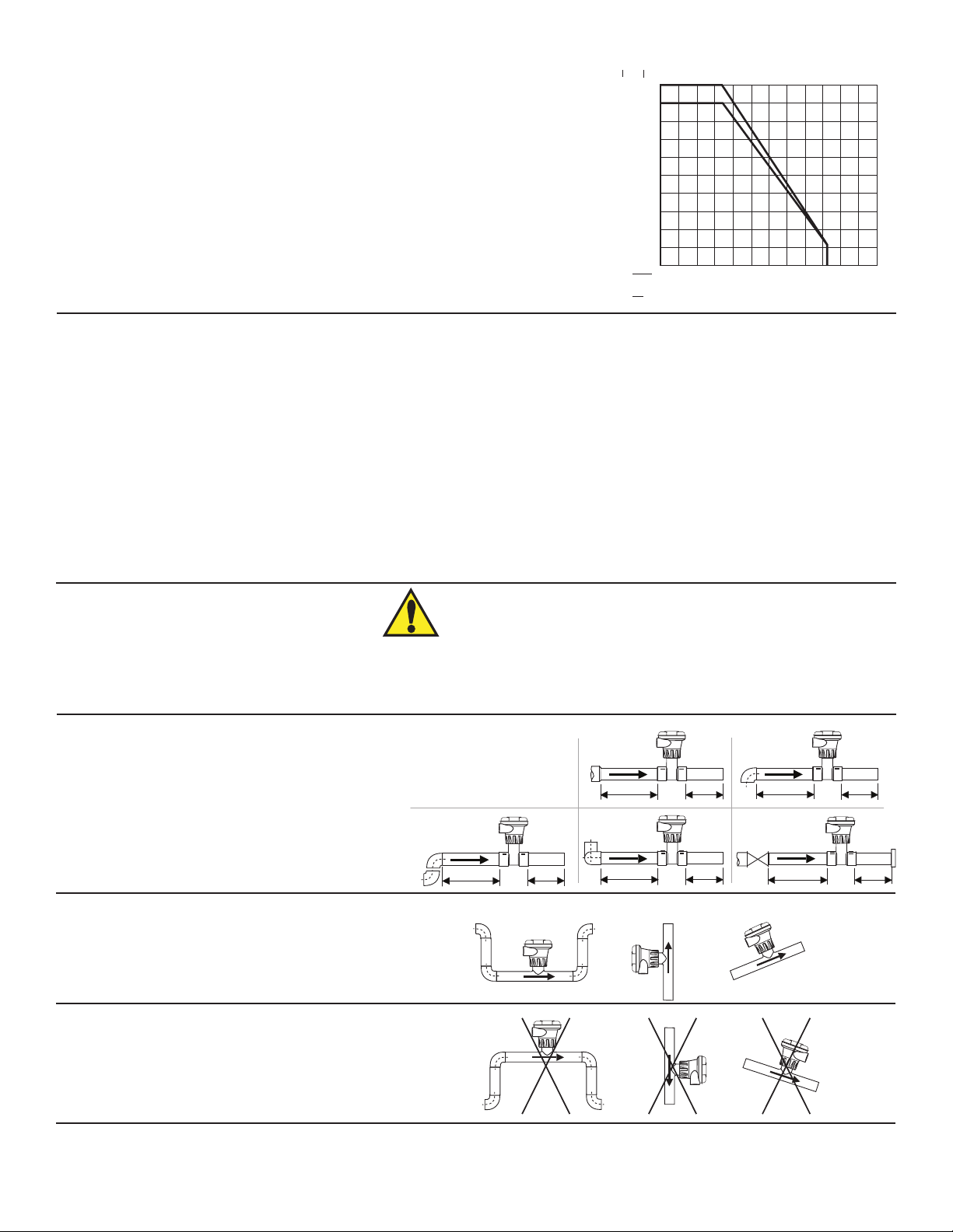
Vertical flow is OK if the pipe remains full at all times.
200
Pressure/TemperatureRatings:
Polypropylene Body:
• 12.5bar(180psi)max.@20°C(68°F)
• 1.7bar(25psi)max.@85°C(185°F)
PVDF Body:
14
11
160
PVDF
Polypropylene
120
8
• 14bar(200psi)max@20°C(68°F)
80
• 1.7bar(25psi)max@85°C(185°F)
Intended Use: Thisproductisintendedforuseinindustrialwatertreatment
6
40
3
andwastewatertreatmentapplicationswherethechemicalcontentandtheuid
temperaturesareconsistentwiththespecicationslistedherein.
°F
04080 120 160 200
240
This device is not approved for use or installation in ammable liquids.
Chemical Compatibility
OMEGAproductsaremanufacturedinavarietyofwettedmaterialstosuitvariousliquidsandchemicals.
Allplasticmaterialsincludingtypicalpipingtypes(PVC,PVDF,PPandPE)aremoreorlesspermeabletocontainedmedia,suchas
waterorvolatilesubstances,includingsomeacids.Thiseffectisnotrelatedtoporosity,butpurelyamatterofgasdiffusionthroughthe
plastic.Iftheplasticmaterialiscompatiblewiththemediumaccordingtotheapplicationguidelines,thepermeationwillnotdamage
theplasticitself.However,iftheplasticenclosesothersensitivecomponents,asisthecasewithOMEGAplasticpaddlewheelsensors,
thesemaybeaffectedordamagedbythemediadiffusingthroughtheplasticbodyandrotor.
PVDFpaddlewheelsensorfailurewhenusedinhotnitricacidapplicationshasbeenreported.PVDFisknowntoallowforsubstantial
permeationofnitricacidconstituentswithoutbeingdamageditself.Noclearguidelinecanbegivenhere,sincethedamagingeffect
tothesensorishighlydependentontemperature,pressureandconcentration.Utilizingsensorsinapplicationswithaggressive
substancesispossible.OnspecialrequestOMEGAcanprovidesensorswithadifferentinternalresinencapsulation(potting)thatwill
delaythedamagingeffectofacidstothesensors.ForallSpecialProductinquiriesortoplaceanorder,pleasecontactOMEGA.
The retaining nuts of paddlewheel sensors are not designed for prolonged contact with aggressive substances. Strong acids,
caustic substances and solvents or their vapor may lead to failure of the retaining nut, ejection of the sensor and loss of the
process uid with possibly serious consequences, such as damage to equipment and serious personal injury. Retaining nuts
Location of Fitting
Recommendedsensorupstream/downstreammounting
requirements
Selectalocationwithsufcientlengthofstraightpipe
immediatelyupstreamofthesensor.
Locatingthesensorinatraporwheretheowisupward
helpstoprotectthesensorfromexposuretoairbubbles
whenthesystemisinoperation.
Thesecongurationsarenotrecommendedbecauseitis
difculttokeepthepipefull.
WARNING
that may have been in contact with such substances, e.g. due to leakage or spilling, must be replaced.
2 Omega FPB Series Flowmeter
Page 5
sensor
cap
tab
notch
Lubricate
O-rings
for ½ in. to 4 in. pipe
97 mm
for 5 to 8 in. pipe
97 mm
Sensor Mounting Position
+45°
-45°
0°
Process
Pipe
+45°
-45°
0°
Tuyau
du fluide de
l'opération
Type Description
2 to 4 inch, cut 1-7/16 inch hole in pipe
Over 4 inch, cut 2-1/8 inch hole in pipe
Special order 14 in. to 36 in.
0.5 to 2 inch versions (MPVC or CPVC)
2.5 to 4 inch versions (PVC)
2 to 4 inch, cut 1-7/16 inch hole in pipe
6 to 8 inch, cut 2-1/8 inch hole in pipe
Available in 10 and 12 inch sizes only
Cut 2-1/2 inch hole in pipe
Weld in place using solvent cement
Iron, Carbon Steel,
316 SS Threaded
tees
Carbon steel &
stainless steel
Weld-on
Weldolets
2 to 4 inch, cut 1-7/16 inch hole in pipe
Over 4 inch, cut 2-1/8 inch hole in pipe
For pipes from DN 15 to 50 mm
PP or PVDF
Type Description
Plastic
tees
Metric
Union
Fitting
PVC
Saddles
Iron
Strap-on
saddles
PVC
Glue-on
Saddles
1.5 in. to 2 in. PVDF insert
Fiberglass
tees
FPT
0.5 to 2 in. versions
Mounts on threaded pipe ends
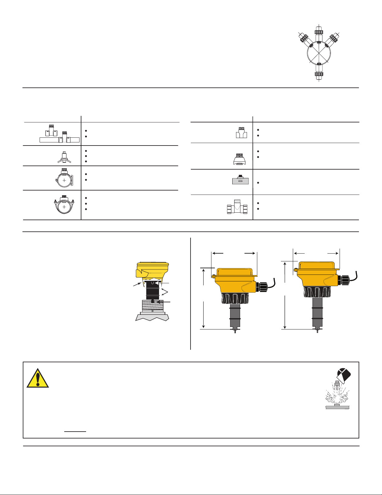
• Horizontalpiperuns:Mountsensorintheupright(0°)positionforbestperformance.Mountata
maximumof45°whenairbubblesarepresent(pipemustbefull).Donotmountonthebottomof
thepipewhensedimentsarepresent.
• Verticalpiperuns:Mountsensorinanyorientation,however,downwardowisnotrecomended.
Upwardowispreferredtoensurefullpipe.
Installation: Pipe ttings
Omegaoffersawideselectionofinstallationttingsthatcontrolthepositionofthepaddlewheelinrelationtothedimensionsofthepipe.
3. Installation
Plasticsensorinstallationtips
• InspectthesensorO-ringsfor
nicksandotherdamagethatmay
compromisetheseal.
• LubricateO-ringswithanon-
petroleumbased,viscouslubricant
(grease)compatiblewiththesystem.
• Usinganalternating/twistingmotion,
lowerthesensorintothetting,
makingsuretheconduitportsonthe
yellowhousingarepointinginthe
directionofow.
• Engageonethreadofthesensorcapthenturnthesensoruntil
thealignmenttabisseatedinthettingnotch.
WARNING!
FAILURE TO FOLLOW THESE INSTRUCTIONS MAY RESULT IN SENSOR BEING EJECTED FROM
THE PIPE!
► DO NOT USE ANY TOOLS ON THE RETAINING CAP. HAND TIGHTEN ONLY.
► DO NOT LUBRICATE THE RETAINING CAP OR THE INSTALLATION FITTING THREADS.
► DO NOT USE THREAD SEALANT ON THE RETAINING CAP OR ON THE PLASTIC FITTING THREADS.
► IF LEAKING IS OBSERVED FROM THE RETAINING CAP, IT INDICATES DEFECTIVE OR WORN O-RINGS ON THE
SENSOR. DO NOT ATTEMPT TO CORRECT BY FURTHER TIGHTENING.
Dimensions
(3.82 in.)
130 mm
(5.12 in.)
FPB 1x1, 1x3 Series
171 mm
(6.73 in.)
(3.82 in.)
FPB 1x2 Series
3Omega FPB Series Flowmeter
Page 6
S1
S2
Blk Red Shld
-
+
S1
S2
Blk Red Shld
-
+
Solid-State Relay Model
WIRING DIAGRAM
BLK
RED
SHLD
Sensor
PW/OUT
+
Power Rating:
5 - 24VDC 0.03 AMP
3-2505.612A
T
P
t
WIRING DIAGRAM
BLK
RED
SHLD
Sensor
PW/OUT
+
Power Rating:
5 - 24VDC 0.03 AMP
3-2505.612A
Solid-State
Relay
Relay Rating:
100mA @ 40VDC
70mA @ 33VAC
3-2505.616A
Load
12
Solid-State
Relay
Relay Rating:
100mA @ 40VDC
70mA @ 33VAC
3-2505.616A
Load
12
Wiring
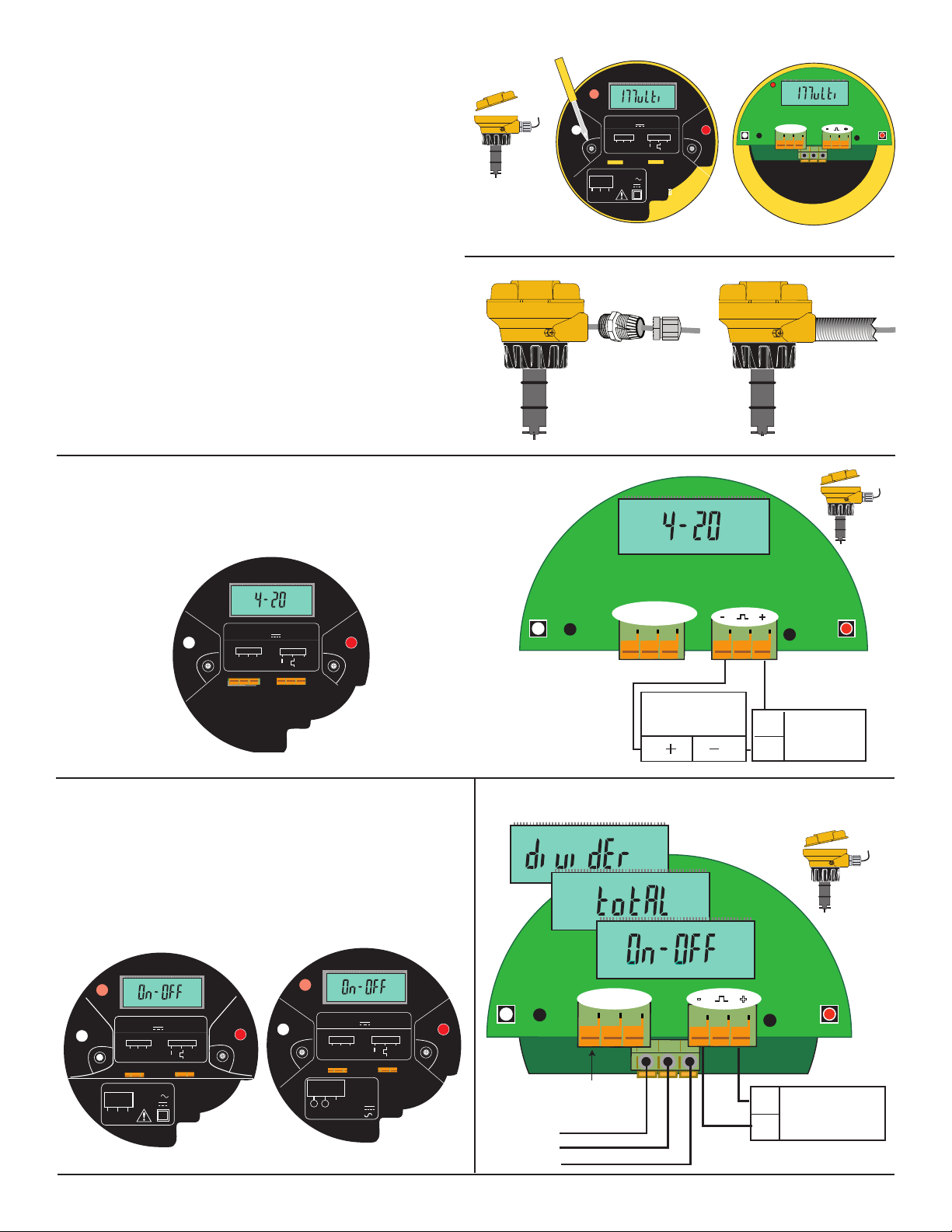
Electricalconnectionstothisproductshouldbemadeonlyby
qualiedpersonnel.
Toaccessthewiringterminals:
• Turnyellowcover¼turncounterclockwisetoremove.
• Removethetworetainingscrewsandremovetheblackcover.
• Routeallcablesthroughtheconduitportsbeforeconnecting
themtotheterminals.
• Wiringterminalsareratedfor16-22AWGconductors.
• Thecablemustbe7to10mmindiameter(0.275to0.394in.)
tosealproperlyintheliquidtightconnector.
• Theconduitportshave½inchNPTthreads.Afterrouting
thecables,sealtheportwithaliquid-tightconduitconnector
(FPM-5000-LTCK)orwithconduit.
• Forconduitinstallations:
• Threadconduitwith½in.NPTthreadsdirectlyintothe
conduitport.
• ForconduitwithISOthreads,usetheblackthreadadapter
includedwiththeconnectorkit.
• TocomplywithNECrequirements,donotuseanymetal
conduitintheinstallation.
Wiring: 4 to 20 mA Output
The4to20mAoutputcanbeconnectedtoChartRecorders,
PLCsoranydevicethatrequiresa4to20mAsignal.
The4to20mAmodelrequiresanexternalpowersourceof
12-32VDC.
Power Rating:
24VDC 0.03 AMP
WIRING DIAGRAM
Sensor
PW/OUT
+
3-2505.611A
SHLD
Dry-Contact
N/O
Relay Rating:
Relay
COM
N/C
BLK
5A @ 250VAC
5A @ 30VDC
RED
Usingtheliquid-tight
connector(FPM-5000-LTCK)
Blk Red Shld
S1
-
+
S2
Usingconduit
T
P
S1
Power Rating:
12 - 32VDC 0.03 AMP
WIRING DIAGRAM
Sensor
Blk Red Shld
BLK
RED
SHLD
PW/OUT
-
t
+
3-2505.614A
+
S2
Wiring: Flow Switch Output (On-Off)
• TheFlowSwitchmodelsprovideasinglerelaythatis
programmableasaHIGHsetpointorLOWsetpoint.
• Therelaymaybeadry-contacttypeorasolidstatetype.
• Thedrycontactrelayrequiresanexternalpowersourceof
24VDC±10%.
• Thesolidstaterelayrequiresanexternalpowersourceof
5 to 24 VDC.
T
P
24VDC 0.03 AMP
WIRING DIAGRAM
Sensor
BLK
Blk Red Shld
RED
Relay Rating:
5A @ 250VAC
Dry-Contact
Relay
5A @ 30VDC
N/C
N/O
COM
Power Rating:
SHLD
PW/OUT
-
+
+
S1
t
3-2505.611A
S2
S1
Solid-State
12
Load
T
P
Power Rating:
5 - 24VDC 0.03 AMP
WIRING DIAGRAM
Sensor
BLK
RED
Relay Rating:
100mA @ 40VDC
70mA @ 33VAC
SHLD
3-2505.616A
PW/OUT
-
Blk Red Shld
Relay
+
+
t
3-2505.612A
S1
Blk Red Shld
Internal sensor
connections
Programmable Logic Controller
Datalogger
Chart Recorder
4 to 20 mA Loop monitor
-
+
S2
+
Power Supply
12 to 32 VDC, 0.03 A
-
Dry Contact Relay Wiring
• ThewiringisidenticalforOn-OffandPulsemodels.
Blk Red Shld
S1
S2
Internal sensor
connections
Normally Open
Common
Normally Closed
-
+
S2
+
Power Supply
24 VDC, 0.03 A
-
4 Omega FPB Series Flowmeter
Page 7
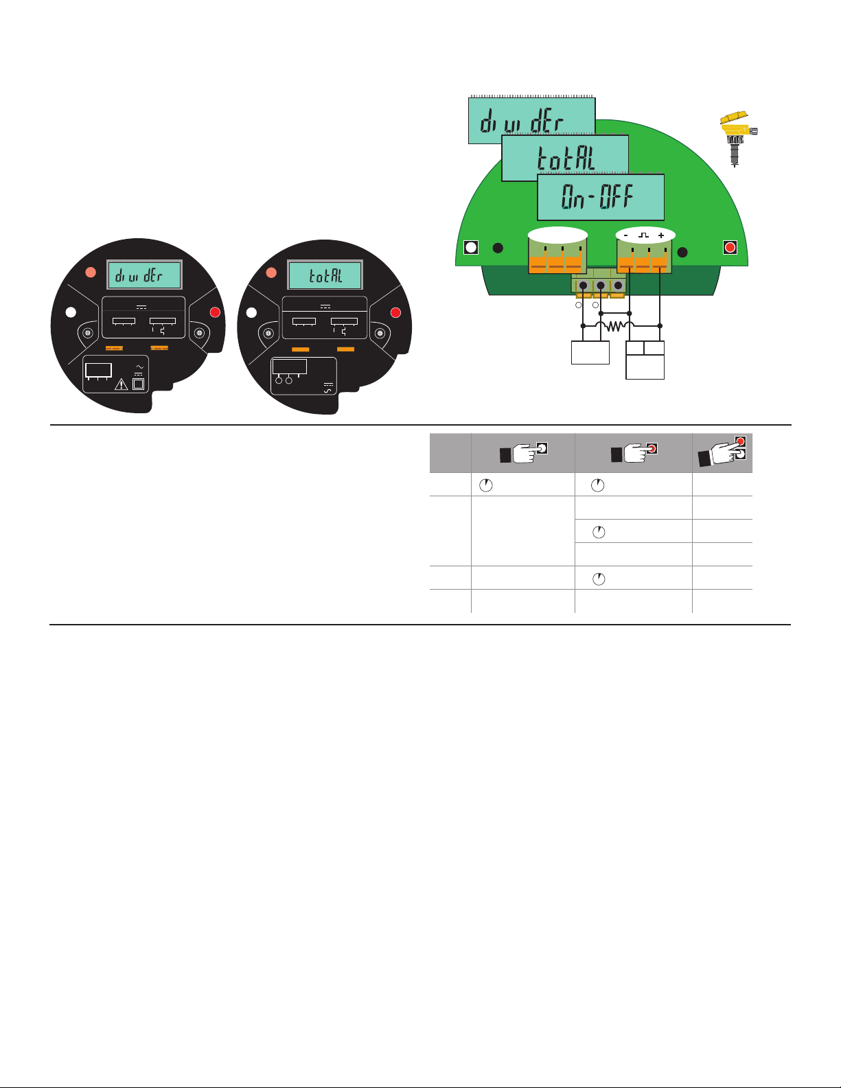
Wiring: Pulse Output
S1
S2
Blk Red Shld
-
+
S1
S2
Blk Red Shld
-
+
Solid-State Relay Model
T
P
t
T
P
t
WIRING DIAGRAM
BLK
RED
SHLD
Sensor
PW/OUT
+
Power Rating:
5 - 24VDC 0.03 AMP
3-2505.612A
WIRING DIAGRAM
BLK
RED
SHLD
Sensor
PW/OUT
+
Power Rating:
24VDC 0.03 AMP
3-2505.611A
Solid-State
Relay
Relay Rating:
100mA @ 40VDC
70mA @ 33VAC
3-2505.616A
Load
1 2
N/O
COM
N/C
Dry-Contact
Relay
Relay Rating:
5A @ 250VAC
5A @ 30VDC
2s
2s
2s
2s
2s
2s
2s
• The"Multi"modeallowsasinglerelaythatisprogrammable
asaFlowSwitch,Volumetricpulseoutputorasasimple
pulse divider output.
• Therelaymaybeadry-contacttypeorasolidstatetype.
• TheDryContactRelayrequiresanexternalpowersourceof
24VDC±10%.
• TheSolidStateRelayrequiresanexternalpowersourceof
5 to 24 VDC.
• SolidStateRelayrequiresapull-upresistor(10Kohm
recommended).Consultyourinstrument/PLCmanualfor
wiringinformation.
Solid State Relay Wiring
• ThewiringisidenticalforOn-OffandPulsemodels.
Blk Red Shld
-
+
S1
Power Rating:
24VDC 0.03 AMP
WIRING DIAGRAM
Sensor
PW/OUT
+
Blk Red Shld
BLK
RED
Relay Rating:
Relay
N/C
COM
5A @ 250VAC
5A @ 30VDC
SHLD
S1
Dry-Contact
N/O
3-2505.611A
-
+
S2
S1
Power Rating:
5 - 24VDC 0.03 AMP
WIRING DIAGRAM
Sensor
BLK
RED
Blk Red Shld
SHLD
3-2505.616A
Solid-State
Relay
Relay Rating:
1 2
100mA @ 40VDC
Load
70mA @ 33VAC
PW/OUT
-
Load
1 2
+
3-2505.612A
+
S2
10KΩ
I/O
Power Supply
5 to 24 VDC,
0.03 A
+–
S2
Operation
MODE
TheFPBFlowmeterisavailablein2differentmodels.The
programmingmenusvarysignicantlyfromonemodeltoanother.
VIEW
Thischartisprovidedinsidetheyellowcovertoassistin
navigatingtheprogrammingmenus.
MENU
EDIT
SAVE
Thistableshowsthedenitionofeachmenufunction,thesettingparametersandthepagewheredetailedinstructionscanbelocated.
1X
1X
1X
→
→
→
→
Display
FlowRate
Next
Menu
Increment
Value
Toggle
1X
1X
1X
→
→
→
→
→
→
Go to
MENU
Display
Current Val
Go to EDIT
Shiftdigitto
right
GotoSAVE
Store
Change
Go to
VIEW
Previous
MODE
Previous
MODE
Previous
MODE
Previous
MODE
N/A
Menu Function Denition Setting Parameters More Information On
FlowUnit LitersorGallonspersec,min,hourorday Seelistonpage7 page7
K-Factor SetPULSESperVOLUMEUNIT 0.0001to999999 page7
4Set SetowRATEtoberepresentedby4mA 0.0000to99999 page7
20Set SetowRATEtoberepresentedby20mA 0.0000to99999 page7
Contrast Adjustvisibilityofliquidcrystaldisplay 1to3 page7
Average Smoothsouterraticowconditions 0to100seconds page8
Sensitivity OverridesAverageforlargeratechanges 0to9 page8
Mode Selecttheoutputmode TotalorDividerorON/OFF page9
P-Factor AsPULSEDIVIDER,dividesinputfreq. 1.0000to99999 page9
P-Factor AsPULSETOTAL,multipliesK-Factor 1.0000to99999 page9
RelayLogic SelectHialarmorLoalarmmode HiorLo page10
RelaySet SetRelaySetpoint 0.0000to99999 page10
RelayHysteresis RateinsideSetpointtoDEENERGIZErelay 0.0000to99999 page10
RelayDelay TimedelaybeforerelayisENERGIZED 0000.0to6400.0 page10
5Omega FPB Series Flowmeter
Page 8
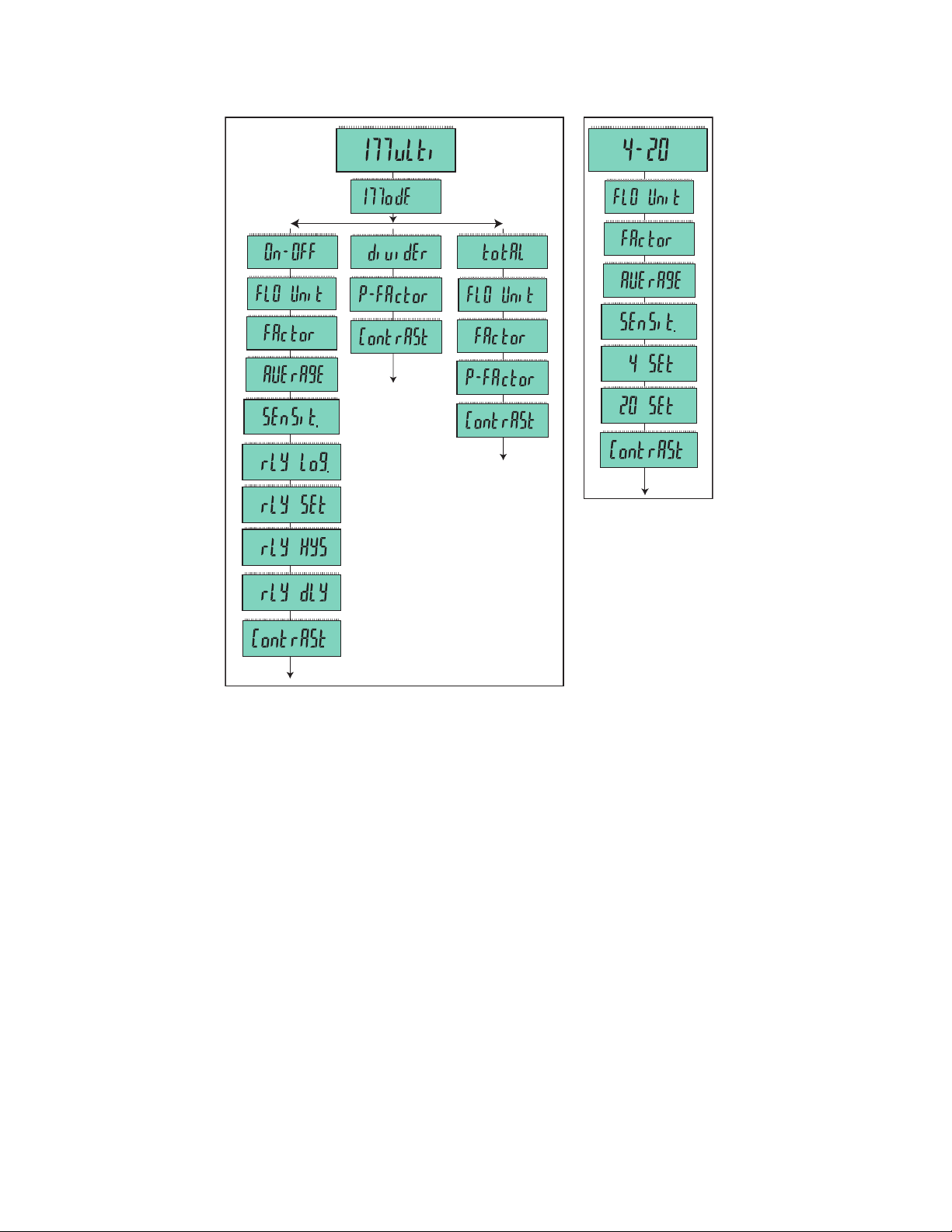
Thistableshowsthemenusequenceforeachmodel.
FPB11X, FPB12X FPB15X
T
P
T
P
T
P
t
t
t
T
P
t
View Mode Function
• Allmodelsdisplaythemodelname:Multi or 4-20.
• Ifthewhitekey(S1)ishelddownforthreeseconds,theowrateisdisplayedfor10minutesbeforerevertingbacktothemodel
name.
IntheMultimodels,ifthe“Multi”menuitemissetto“divider”,thenthedividedpulseoutputwillbedisplayedinpulses/seconds(p/s).
6 Omega FPB Series Flowmeter
Page 9
T
P
t
T
P
t
T
P
t
Repeat until
Choose:
t
T
P
t
T
P
t
Flow Units
t
T
P
t
T
P
t
K-Factor
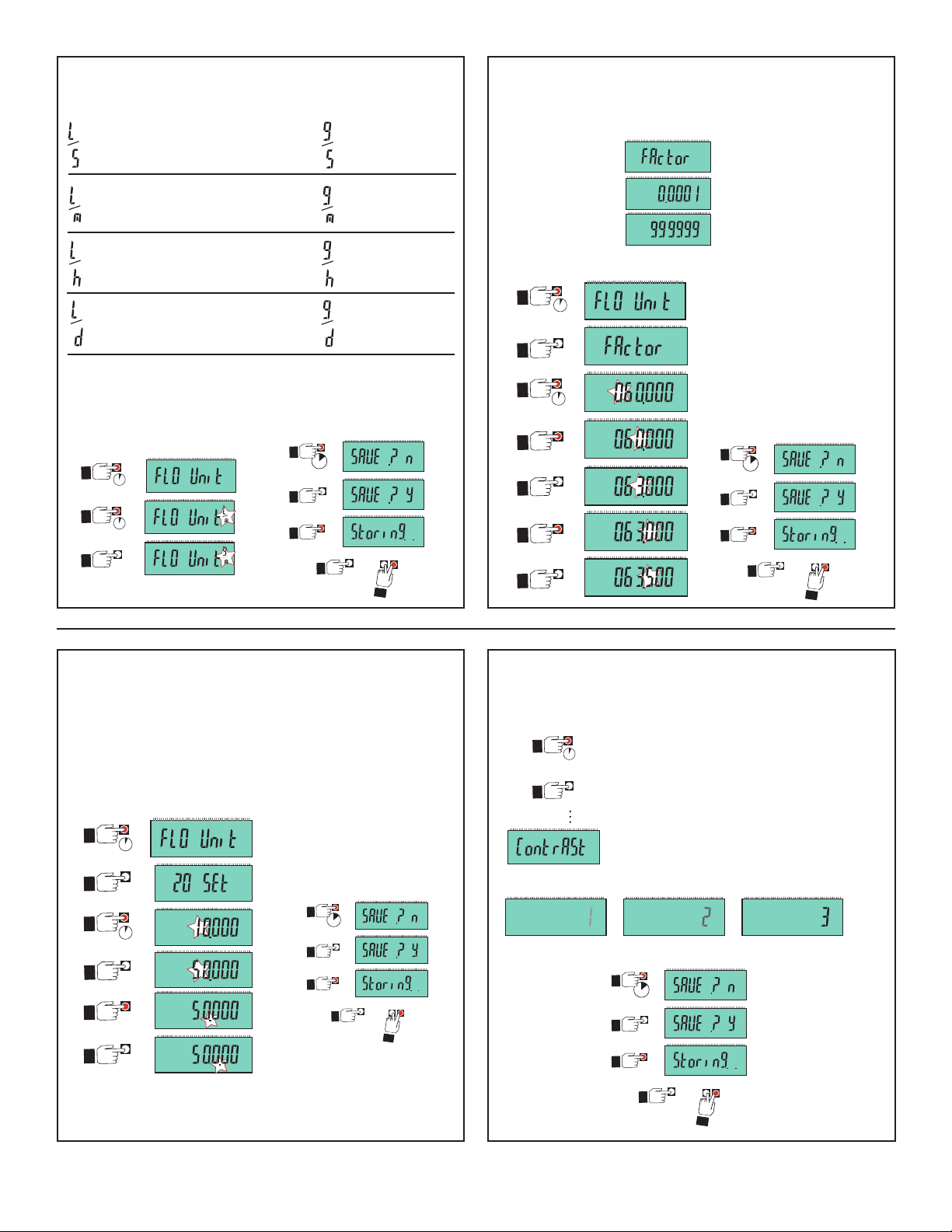
Selectthevolumetricunitsfortheowmeasurement.
Liters/second
Liters/minute
Gallons/second
Gallons/minute
(Factorysetting)
Liters/hour
Liters/day
Gallons/hour
Gallons/day
Example: Set the Flow Units to Gallons per minute:
Save the new setting:
1.
2.
2s
2s
3.
2s
Go to next
menu item
Return to
Normal Operation
Thefactorysettingis60.0000.
LocatetheK-factorinthetablesonpage10.
Minimum value
Maximum value
Example: Set the K-Factor to 63.5 Pulses per Gallon:
1.
2s
2.
3.
2s
Save the new setting:
4.
5.
6.
7.
x2
x3
x5
P
2s
Return to
Go to next
menu item
Normal Operation
Set 4 and Set 20
Thesetwofunctionsareusedtospanthe4to20mAoutput
signaltotherequiredrange.
Thefactorysettingis4-20mA=0to10.000
Onlythe20mAspanisillustratedhere.
Example: Set 20 mA = 500 GPM.
1.
2s
2.
3.
x5
2s
Save the new setting:
2s
Set Contrast
AllmodelsoftheFPBhavetheCONTRASTadjustment.Itis
alwayslocatedattheendofthemenu.
1.
2.
Toaccesstheadjustment,
2s
enterthemenuandscroll
untiltheContrastdisplay
x1
appears.
Therearethreelevelsofadjustment.
Thefactorysettingof3isthehighest
contrastsetting.
OR OR
Save the new setting:
4.
5.
6.
x4
2s
x2
Go to next
menu item
Return to
Normal Operation
Go to next
menu item
Return to
Normal Operation
7Omega FPB Series Flowmeter
Page 10
10 s2 s 20 s 30 s 40 s 50 s 60 s 70 s
No AVERAGING, no SENSITIVITY
No AVERAGING, no SENSITIVITY
AVERAGING only
No AVERAGING, no SENSITIVITY
AVERAGING and SENSITIVITY
AVERAGING only
Averaging and Sensitivity Settings
2s
2s
x2
x2
x4
1.
2.
3.
4.
5.
t
T
P
t
T
P
t
2s
Go to next
menu item
Return to
Normal Operation
t
T
P
t
T
P
t
• Becauseidealowconditionsareoftenimpossibletoachieve,theowrateisoftenerratic,whichcausesanycontrolfeatures
(e.g.,relays,4to20mAloops,etc.)thatareassociatedwiththeowratetobeerratic.
• Thebestsolutiontotheseproblemsistocorrectanypipingdeciencythatcausestheinstability.Thismayinvolvelongerstraight
runsupstream,reducingthepipesizetomaintainafullpipeatalltimes,andotherinstallationchanges.Inmanysituations,
however,thesemeasuresaresimplynotpossible.
• TheFPBmeterprovidestwotoolsthataredesignedto"workaround"thesedeciencies.TheAveragingandtheSensitivity
featuresshouldbestudiedbeforemakingadjustments.
Averaging Time in Seconds (Factory set: 0 seconds)
• Setthetimethemeterwilluseastheaveragingperiod.Therangeisfrom0(noaverageappliedtoinput)to100(secondsof
averagingappliedtoinput).
Usehigheraveragingtimestosmooththedisplayandcurrentoutputwheretheowinthepipeiserratic.
Quick Response Sensitivity (Factory set: 0)
• SettherelativedegreeofchangeintheowraterequiredtoallowtheFPBtodisabletheAVERAGINGandjumptoanewowrate
immediately.Thescaleisfrom0(Leastsensitive,averagingisneverdisabled.)to9(averysmallchangeinowratewilldisable
theaveraging).
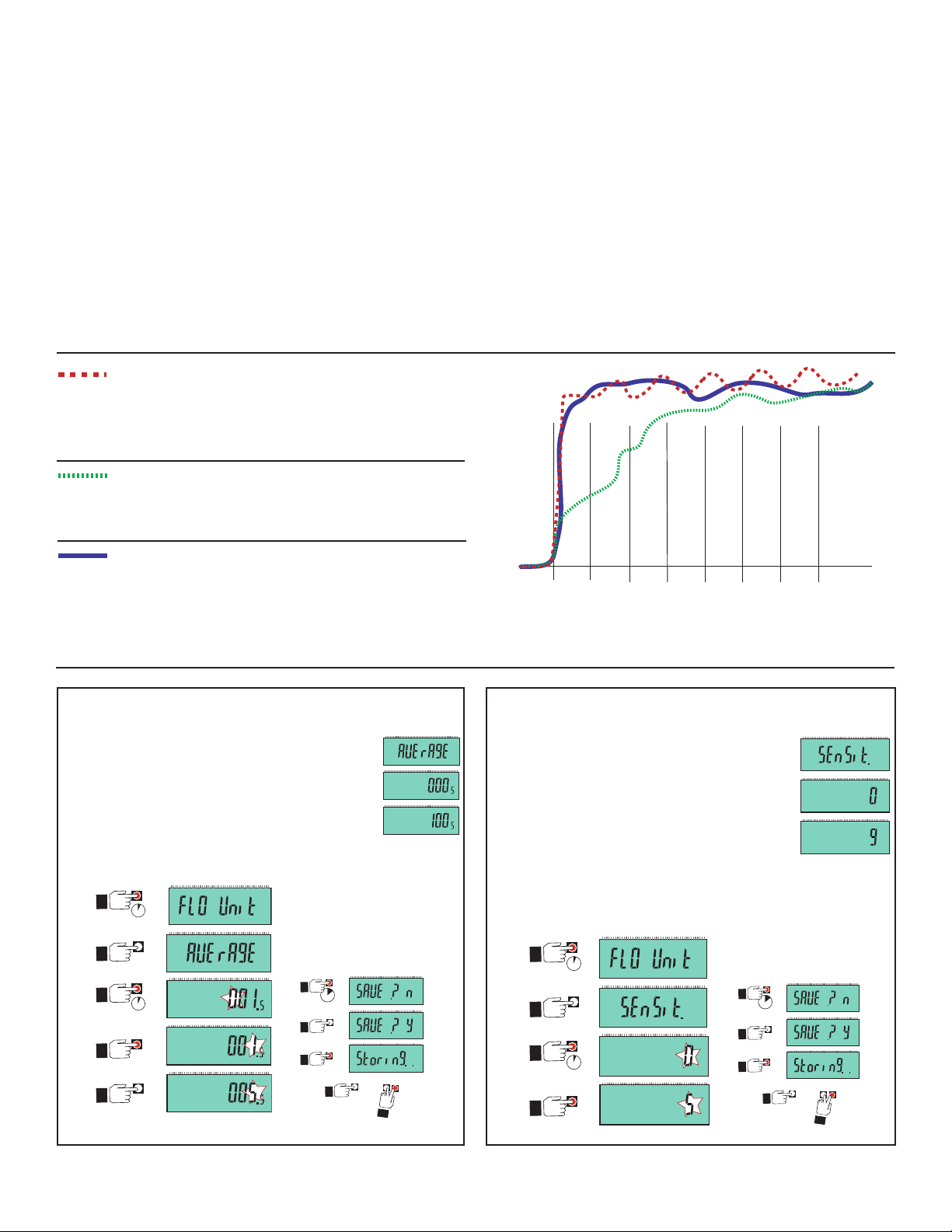
WithAVERAGINGsetto0(zero)andwithSENSITIVITYsettozero,
theFPBrespondstoeveryunstableshiftintheow.Thedashedred
linerepresentstheactualoutputoftheowsensorinunstableow
conditions.
WithAVERAGINGsetto50secondsandSENSITIVITYstillsetto
zerotheowrateisstabilized,butasharpchangeinowrateisnot
representedfor50secondsorlonger.(dottedgreenline).
WithAVERAGINGat50secondsandSENSITIVITYsetto4OR5,
theowrateisstabilized,whilethesuddenshiftinowisreected
veryquickly.(Solidblueline)
NOTE:TheSENSITIVITYfunctionisineffectiveiftheAVERAGINGfunctionissettozero(seconds).
Set Averaging
Thefactorysettingis0(zero).
Minimum value
Set Sensitivity
Thefactorysettingis0(zero).
Maximum value
Example:
Set the Averaging for 50 seconds.
Example: Set the Sensitivity to 5.
Save the new setting:
1.
2s
2.
x3
3.
2s
Minimum value
Maximum value
Save the new setting:
2s
8 Omega FPB Series Flowmeter
4.
x5
Go to next
menu item
Return to
Normal Operation
Page 11
t
T
P
t
T
P
t
Mode
t
t
t
T
P
T
P
t
P-Factor
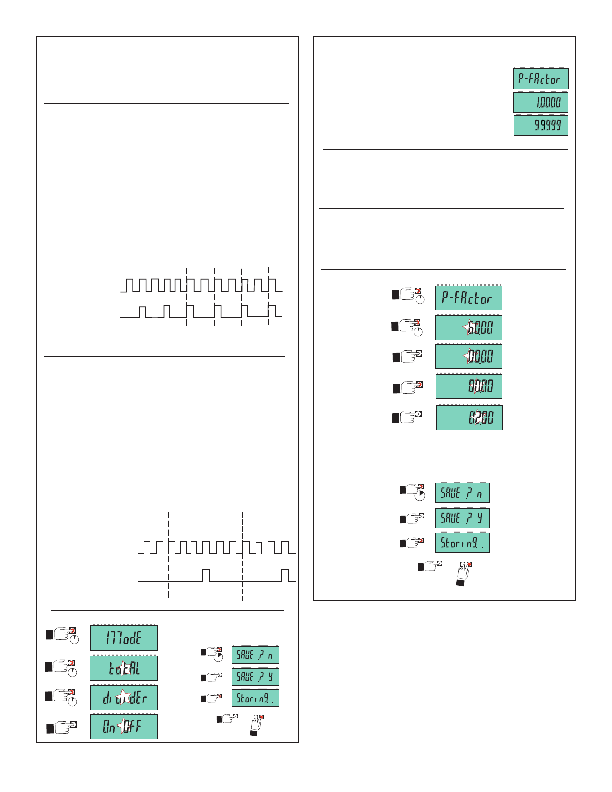
SelectDIVIDERorTOTALoperation.
ThefactorysettingisTOTAL.
PULSE DIVIDER Output = Input pulses ÷ P-Factor
DIVIDERallowsyoutosetascalingvalue(P-Factor)from
1.0000to99999.
Example:IftheP-Factorissetfor2,thentheFPBwilloutput
onepulseforevery2pulsesreceivedfromthesensor.
Thisselectionenablestheoutputfrequencytobescaleddown
tomatchassociatedequipmentcapabilities.
WhenusingthePULSEDIVIDERoutput,associatedequipment
mustdividetheK-FactorsinthismanualbytheP-Factorfor
correctcalibration.
1 2 3 5 7 94 6 8
1110 12
PulsesIN
1 2 3 4
5 6
PulsesOUT
PULSE TOTAL Output = Input pulses ÷ (K-Factor × P-Factor)
TOTALisatraditionalpumppulserfunction.Thisselectionwill
allowtheentryofaK-Factortodeneavolumetricunit,thenset
aP-Factortodenethenumberofvolumetricunitsrequiredto
generateonepulseout.
Thefactorysettingis1.0000
Minimum value
Maximum value
In PULSE DIVIDER mode the P-Factor divides:
Thepulsestreamfromthepaddlewheelsensorwillbedivided
bytheP-Factor.Theresultingfrequencyisoutputthrougha
relay.
In PULSE TOTAL mode the P-Factor multiplies:
Thepulsestreamfromthepaddlewheelsensorisdivided
bytheK-FactorMULTIPLIEDbytheP-factor.Theresulting
frequencyisoutputthrougharelay.
1.
2s
2.
3.
4.
5.
2s
x4
x2
Example:
SettheTotalPulseoutputsothereisonepulseoutforeach2
gallonsthatpassesthesensoriftheK-Factoris3.0.
1. K-Factor=3.0(pulsesinpergallon)
2. P-Factor=2(gallonsoutperpulse)
1 Gal 4 Gal
2 Gal 3 Gal
21 3 54 6 87 9 1110 12
PulsesIN
PulsesOUT
2s
2s
2s
T
P
t
1
Save the new setting:
2s
Return to
Go to next
menu item
Normal Operation
Save the new setting:
2s
2
Go to next
menu item
Return to
Normal Operation
9Omega FPB Series Flowmeter
Page 12
t
t
T
P
t
T
P
t
Set Relay operation
t
T
P
t
T
P
t
t
t
P
T
t
t
T
P
x4
2s
2s
1.
2.
3.
4.
t
T
P
t
T
P
t
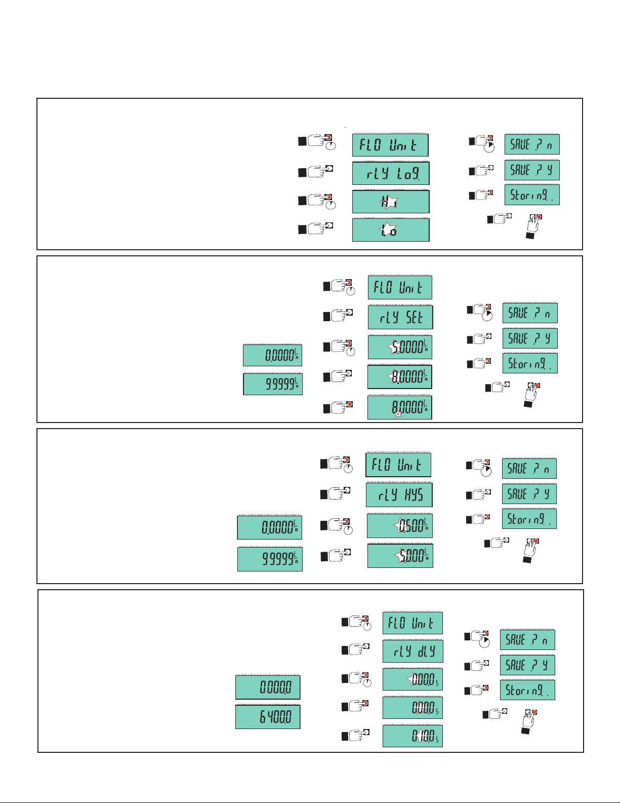
TheFlowSwitchhasonerelay(SPDTorsolid-state)thatcanbeprogrammedasaHIGH(Hi)
alarmoraLOW(Lo)alarm.
1. Select HI or LO Relay Alarm logic
AHIalarmwillbeactivatedwhenthe
owraterisesABOVEthesetpoint.
ALOalarmwillbeactivatedwhenthe
owratefallsBELOWthesetpoint.
ThefactorysettingisHi(gh).
2. Program the SETPOINT.
Example:ChangetheSetpointto8.0000:
TheSETPOINTistheowratewheretherelaywillbe
energized.Thefactorysettingis5.0000.
Minimum value
Maximum value
Example:ChangetheRelayLogictoLow:
1.
2.
3.
4.
5.
2s
x5
2s
x3
Save the new setting:
2s
Return to
Go to next
menu item
Normal Operation
Save the new setting:
2s
Return to
Go to next
menu item
Normal Operation
3. Program the HYSTERESIS.
Example:ChangetheHysteresisto5.0000:
Hysteresisholdsarelayenergizeduntiltheowrate
1.
2s
movesthisamountpastthesetpoint.
Thefactorysettingis0.5000
Minimum value
Maximum value
4. Program the DELAY.
Whentheowratereachesthesetpoint,theFPBwill
waitthislong(inseconds)beforetriggeringthealarm.
Thefactorysettingis0000.0seconds.
Minimum value
2.
3.
4.
x6
2s
x5
Example:ChangetheDelayto10.0:
1.
2.
3.
4.
2s
x7
2s
Maximum value
5.
Save the new setting:
2s
Return to
Go to next
menu item
Normal Operation
Save the new setting:
2s
Return to
Go to next
menu item
Normal Operation
10 Omega FPB Series Flowmeter
Page 13
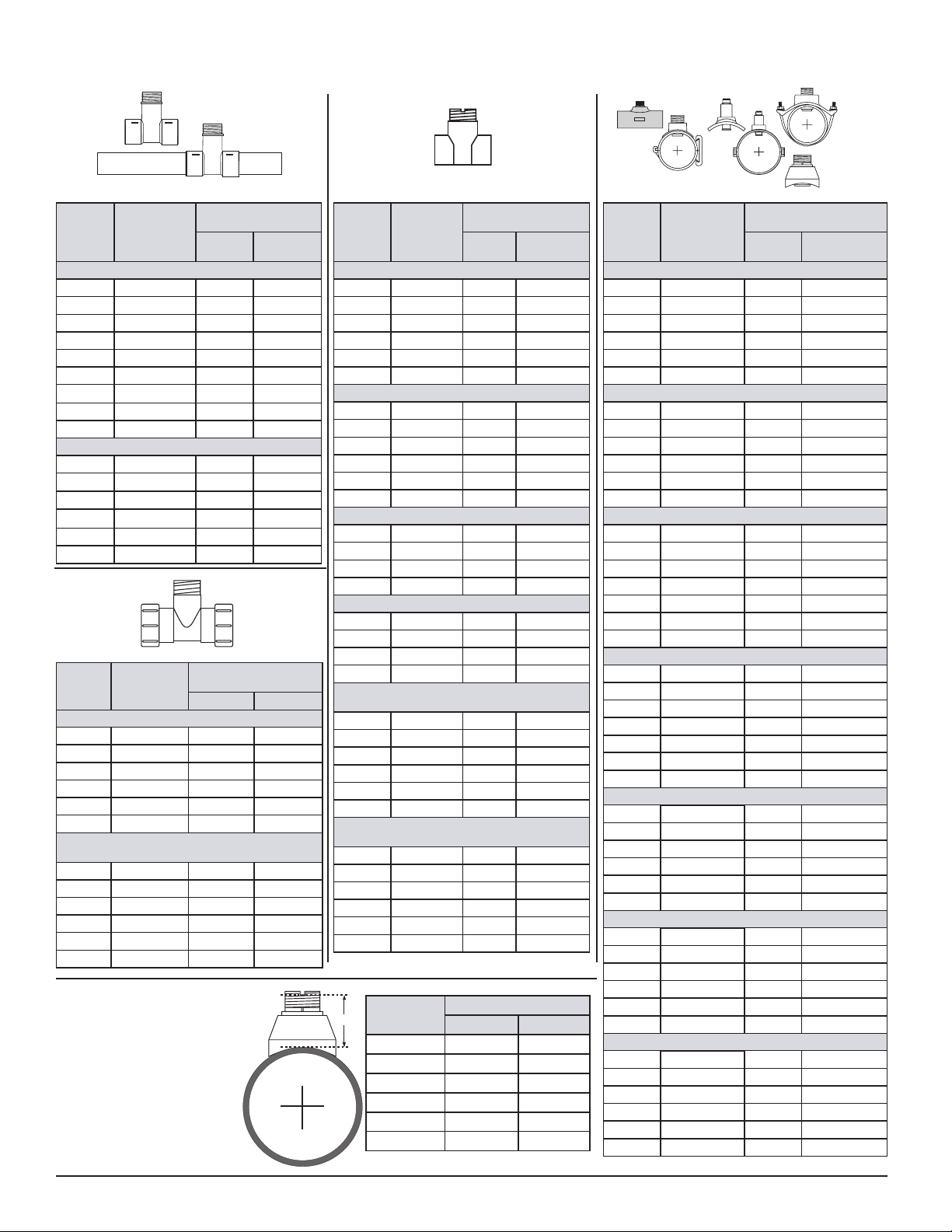
K-Factors
WhenusingthePULSEDIVIDERoutput,associatedequipmentmustdividetheK-FactorbytheP-Factor.
Molded Tees SaddlesandWeldoletsMetal Tees
PIPE
SIZE
(IN.)
SCH 80 MOLDED TEES FOR SCH 80 PVC PIPE
1/2
3/4
1
1-1/4
1-1/2
2
2-1/2
3
4
SCH 80 CPVC TEES FOR SCH 80 CPVC PIPE
1/2
3/4
1
1-1/4
1-1/2
2
FITTING
FP-5305M
FP-5307M
FP-5310M
FP-5312M
FP-5315M
FP-5320M
FP-5325
FP-5330
FP-5340
FP5305CM
FP-5307CM
FP-5310CM
FP-5312CM
FP-5315CM
FP-5320CM
FPB Series
Paddlewheel
U.S.
GAL
1027.1 271.37
583.19 154.08
335.53 88.65
178.79 47.24
121.42 32.08
71.44 18.87
42.994 11.359
26.652 7.0414
15.006 3.9645
1027.1 271.37
583.19 154.08
335.53 88.65
178.79 47.24
121.42 32.08
71.44 18.87
LITERS
UnionTees
PIPE
SIZE
(IN.)
PVDF FITTINGS (DIN/ISO AND BS AND ANSI)
DN15
DN20
DN25
DN32
DN40
DN50
POLYPROPYLENE FITTINGS (DIN/ISO AND BS
AND ANSI)
FITTING
FP-5105PO
FP-5107PO
FP-5110PO
FP-5112PO
FP-5115PO
FP-5120PO
DN15 FP-5105PO 952.87 251.75
DN20 FP-5107PO 563.10 148.77
DN25 FP-5110PO 291.60 77.042
DN32 FP-5112PO 169.22 44.709
DN40 FP-5115PO 103.90 27.450
DN50 FP-5120PO 60.789 16.060
FPB Series
Paddlewheel
U.S. GAL LITERS
827.26 218.56
489.87 129.42
283.55 74.915
158.59 41.899
86.980 22.980
50.385 13.312
H-Dimensions
Theplasticinsertin
WeldoletttingsMUSTbe
removedduringthewelding
process.Whenreinstalled,
itisimportantthattheinsert
bethreadedtotheproper
height("H"dimension).
PIPE
SIZE
(IN.)
CARBON STEEL TEES ON SCH 40 PIPE
1/2
3/4
1
1-1/4
1-1/2
2
STAINLESS STEEL TEES ON SCH 40 PIPE
1/2
3/4
1
1-1/4
1-1/2
2
GALVANIZED IRON TEES ON SCH 40 PIPE
1
1-1/4
11/2
2
BRONZE TEES ON SCH 40 PIPE
1
1-1/4
1-1/2
2
COPPER TEE FITTINGS ON COPPER PIPE
SCH K
1/2
3/4
1
1-1/4
1-1/2
2
COPPER TEE FITTINGS ON COPPER PIPE
SCH L
1/2
3/4
1
1-1/4
1-1/2
2
"H"
FITTING
FP-5305CS
FP-5307CS
FP-5310CS
FP-5312CS
FP-5315CS
FP-5320CS
FMG-5305
FMG-5307
FMG-5310
FMG-5312
FMG-5315
FMG-5320
FP-5310GI
FP-5312GI
FP-5315GI
FP-5320GI
FP-5310BR
FP-5312BR
FP-5315BR
FP-5320BR
FP-5305CU
FP-5307CU
FP-5310CU
FP-5312CU
FP-5315CU
FP-5320CU
FP-5305CU
FP-5307CU
FP-5310CU
FP-5312CU
FP-5315CU
FP-5320CU
Nominal
Pipe size
2½in. 2.33 59.18
3 in. 2.32 58.92
4 in. 2.30 58.42
5 in.
6 in. 2.96 75.18
8in. 2.73 69.34
FPB Series
Paddlewheel
U.S.
GAL
756.00 199.74
438.69 115.90
286.78 75.768
121.22 32.026
91.139 24.079
54.468 14.391
734.20 193.98
412.10 108.88
252.70 66.764
128.12 33.849
77.320 20.428
45.780 12.095
213.01 56.277
127.75 33.751
94.401 24.941
59.420 15.699
213.01 56.277
127.75 33.751
94.401 24.941
59.420 15.699
917.84 242.50
428.27 113.15
256.43 67.749
176.44 46.615
115.69 30.565
63.385 16.746
858.22 226.74
385.74 101.91
241.64 63.841
170.90 45.152
112.03 29.598
61.74 16.310
LITERS
“H” dimension
inches mm
3.09 78.48
PIPE
SIZE
(IN.)
SCH 80 PVC SADDLES FOR SCH 80 PVC PIPE
2
2-1/2
3
4
6
8
SCH 80 PVC SADDLE ON SCH 40 PVC PIPE
2
2-1/2
3
4
6
8
SCH 80 IRON SADDLES ON SCH 80 PIPE
2
2-1/2
3
4
5 FP-5350GS 12.180 3.218
6
8
SCH 80 IRON SADDLE ON SCH 40 PIPE
2
2-1/2
3
4
5 FP-5350GS 11.040 2.917
6
8
STAINLESS STEEL WELDOLETS ON SCH 40 PIPE
2-1/2
3
4
5
6
8
CARBON STEEL WELDOLETS ON SCH 40 PIPE
2-1/2
3
4
5
6
8
COPPER/BRONZE BRAZOLETS ON SCH 40 PIPE
2-1/2
3
4
5
6
8
FITTING
FP-5320S
FP-5325S
FP-5330S
FP-5340S
FP-5360S
FP-5380S
FP-5320S
FP-5325S
FP-5330S
FP-5340S
FP-5360S
FP-5380S
FP-5320GS
FP-5325GS
FP-5330GS
FP-5340GS
FP-5360GS
FP-5380GS
FP-5320GS
FP-5325GS
FP-5330GS
FP-5340GS
FP-5360GS
FP-5380GS
FMG-5325
FMG-5330
FMG-5340
FMG-5350
FMG-5360
FMG-5380
FP-5325CS
FP-5330CS
FP-5340CS
FP-5350CS
FP-5360CS
FP-5380CS
FP-5325BR
FP-5330BR
FP-5340BR
FP-5350BR
FP-5360BR
FP-5381BR
FPB Series
Paddlewheel
U.S.
GAL
66.739 17.633
42.994 11.359
26.652 7.0414
15.006 3.9645
8.3246 2.1994
5.0164 1.3253
54.700 14.452
37.159 9.8175
23.697 6.2608
13.456 3.5552
7.4594 1.9708
4.5292 1.1966
64.720 17.099
42.480 11.223
26.420 6.980
14.700 3.884
8.4400 2.230
4.9000 1.295
53.640 14.172
37.600 9.934
23.220 6.135
13.260 3.503
7.2400 1.913
4.4000 1.162
37.600 9.9339
24.340 6.4306
13.920 3.6777
10.860 2.8692
7.5200 1.9868
4.3400 1.1466
37.600 9.9339
24.340 6.4306
13.920 3.6777
10.860 2.8692
7.5200 1.9868
4.3400 1.1466
37.600 9.934
24.340 6.431
13.920 3.678
10.860 2.869
7.5200 1.987
4.3400 1.147
LITERS
11Omega FPB Series Flowmeter
Page 14

Maintenance and Cleaning
TheOmegaFPBSeriesrequiresverylittlemaintenance.
• Ifthepaddlewheelbecomesfouled,itcanbecleanedwithmilddetergentsandasmallbrush.
• TheelectronicsportionoftheFPBdoesnotrequiremaintenanceorcleaning.
Rotor Replacement Procedure
1. Toremovetherotor,insertasmallscrewdriverbetweentherotorandtheearofthesensor.
2. Twistthescrewdriverbladetoextheearoutwardenoughtoremoveoneendoftherotorandpin.
DONOTextheearanymorethannecessary!Ifitbreaks,thesensorcannotberepaired.
3. Installthenewrotorbyinsertingonetipofthepinintothehole,thenextheoppositeearback
enoughtosliprotorintoplace.
Ordering Information
Mfr. Part No. Description
FPB system for 0.5 in. to 4 in. pipes, with Polypropylene body, Black PVDF rotor, Titanium pin, FPM O-rings
FPB111 Pulse/FlowSwitchviaDry-ContactRelay,IntegralMount
FPB121 Pulse/FlowSwitchviaSolid-StateRelay,IntegralMount
FPB151 4-20mA,IntegralMount
FPB system for 5 in. to 8 in. pipes, with polypropylene body, Black PVDF rotor, Titanium pin, FPM O-rings
FPB152 4-20mA,IntegralMount
FPB system for 0.5 in. to 4 in. pipes, with natural PVDF body, rotor and pin, FPM O-rings
FPB153 4-20mA,IntegralMount
Accessories
Part No. Description
FMK-2536-1 Rotor,PVDFBlack
FMK-2536-5 RotorandPin,PVDFNatural
FMK-1546-1 RotorPin,Titanium
FMK-1546-2 RotorPin,Hastelloy-C
FMK-1546-3 RotorPin,Tantalum
FPP-1220-0021 O-Ring,FPM
FPP-1224-0021 O-Ring,EPDM
FMK-31536-1 SensorPlug,Polypro
FP90RC RCFilterkit(forrelayuse)
FPM-5000-LTCK LiquidTightConnectionKit
12 Omega FPB Series Flowmeter
Page 15

WARRANTY/DISCLAIMER
OMEGA ENGINEERING, INC. warrants this unit to be free of defects in materials and workmanship for a
period of 13 months from date of purchase. OMEGA’s WARRANTY adds an additional one (1) month
grace period to the normal one (1) year product warranty to cover handling and shipping time. This
ensures that OMEGA’s customers receive maximum coverage on each product.
If the unit malfunctions, it must be returned to the factory for evaluation. OMEGA’s Customer Service
Department will issue an Authorized Return (AR) number immediately upon phone or written request.
Upon examination by OMEGA, if the unit is found to be defective, it will be repaired or replaced at no
charge. OMEGA’s WARRANTY does not apply to defects resulting from any action of the purchaser,
including but not limited to mishandling, improper interfacing, operation outside of design limits,
improper repair, or unauthorized modification. This WARRANTY is VOID if the unit shows evidence of
having been tampered with or shows evidence of having been damaged as a result of excessive corrosion;
or current, heat, moisture or vibration; improper specification; misapplication; misuse or other operating
conditions outside of OMEGA’s control. Components in which wear is not warranted, include but are not
limited to contact points, fuses, and triacs.
OMEGA is pleased to offer suggestions on the use of its various products. However,
OMEGA neither assumes responsibility for any omissions or errors nor assumes liability for
any damages that result from the use of its products in accordance with information provided
by OMEGA, either verbal or written. OMEGA warrants only that the parts manufactured by the
company will be as specified and free of defects. OMEGA MAKES NO OTHER WARRANTIES OR
REPRESENTATIONS OF ANY KIND WHATSOEVER, EXPRESSED OR IMPLIED, EXCEPT THAT OF
TITLE, AND ALL IMPLIED WARRANTIES INCLUDING ANY WARRANTY OF MERCHANTABILITY
AND FITNESS FOR A PARTICULAR PURPOSE ARE HEREBY DISCLAIMED. LIMITATION OF
LIABILITY: The remedies of purchaser set forth herein are exclusive, and the total liability of
OMEGA with respect to this order, whether based on contract, warranty, negligence,
indemnification, strict liability or otherwise, shall not exceed the purchase price of the
component upon which liability is based. In no event shall OMEGA be liable for
consequential, incidental or special damages.
CONDITIONS: Equipment sold by OMEGA is not intended to be used, nor shall it be used: (1) as a “Basic
Component” under 10 CFR 21 (NRC), used in or with any nuclear installation or activity; or (2) in medical
applications or used on humans. Should any Product(s) be used in or with any nuclear installation or
activity, medical application, used on humans, or misused in any way, OMEGA assumes no responsibility
as set forth in our basic WARRANTY/DISCLAIMER language, and, additionally, purchaser will indemnify
OMEGA and hold OMEGA harmless from any liability or damage whatsoever arising out of the use of the
Product(s) in such a manner.
RETURN REQUESTS/INQUIRIES
Direct all warranty and repair requests/inquiries to the OMEGA Customer Service Department.
BEFORE RETURNING ANY PRODUCT(S) TO OMEGA, PURCHASER MUST OBTAIN AN AUTHORIZED
RETURN (AR) NUMBER FROM OMEGA’S CUSTOMER SERVICE DEPARTMENT (IN ORDER TO AVOID
PROCESSING DELAYS). The assigned AR number should then be marked on the outside of the return
package and on any correspondence.
The purchaser is responsible for shipping charges, freight, insurance and proper packaging to prevent
breakage in transit.
FOR WARRANTY RETURNS, please have the
following information available BEFORE contacting
OMEGA:
1. Purchase Order number under which the product
was PURCHASED,
2. Model and serial number of the product under
warranty, and
3. Repair instructions and/or specific problems
relative to the product.
OMEGA’s policy is to make running changes, not model changes, whenever an improvement is possible. This affords
our customers the latest in technology and engineering.
OMEGA is a registered trademark of OMEGA ENGINEERING, INC.
© Copyright 2016 OMEGA ENGINEERING, INC. All rights reserved. This document may not be copied, photocopied,
reproduced, translated, or reduced to any electronic medium or machine-readable form, in whole or in part, without the
prior written consent of OMEGA ENGINEERING, INC.
FOR NON-WARRANTY REPAIRS,
OMEGA for current repair charges. Have
the following information available BEFORE
contacting OMEGA:
1. Purchase Order number to cover the COST
of the repair,
2. Model and serial number of the product, and
3. Repair instructions and/or specific problems
relative to the product.
consult
13Omega FPB Series Flowmeter
Page 16

Where Do I Find Everything I Need for
Process Measurement and Control?
OMEGA…Of Course!
Shop online at omega.com
TEMPERATURE
MU
Thermocouple, RTD & Thermistor Probes, Connectors, Panels & Assemblies
MU
Wire: Thermocouple, RTD & Thermistor
MU
Calibrators & Ice Point References
MU
Recorders, Controllers & Process Monitors
MU
Infrared Pyrometers
PRESSURE, STRAIN AND FORCE
MU
Transducers & Strain Gages
MU
Load Cells & Pressure Gages
MU
Displacement Transducers
MU
Instrumentation & Accessories
FLOW/LEVEL
MU
Rotameters, Gas Mass Flowmeters & Flow Computers
MU
Air Velocity Indicators
MU
Turbine/Paddlewheel Systems
MU
Totalizers & Batch Controllers
SM
pH/CONDUCTIVITY
MU
pH Electrodes, Testers & Accessories
MU
Benchtop/Laboratory Meters
MU
Controllers, Calibrators, Simulators & Pumps
MU
Industrial pH & Conductivity Equipment
DATA ACQUISITION
MU Communications-Based Acquisition Systems
MU Data Logging Systems
MU Wireless Sensors, Transmitters, & Receivers
MU Signal Conditioners
MU Data Acquisition Software
HEATERS
MU
Heating Cable
MU
Cartridge & Strip Heaters
MU
Immersion & Band Heaters
MU
Flexible Heaters
MU
Laboratory Heaters
ENVIRONMENTAL
MONITORING AND CONTROL
MU
Metering & Control Instrumentation
MU
Refractometers
MU
Pumps & Tubing
MU
Air, Soil & Water Monitors
MU
Industrial Water & Wastewater Treatment
MU
pH, Conductivity & Dissolved Oxygen Instruments
6-2537.090-OM (D-02/17) M4591/0217
 Loading...