

Page 1
OMEGA FP85A Flow Transmitter Instructions
CAUTION!
Remove power to unit before wiring input and output connections.
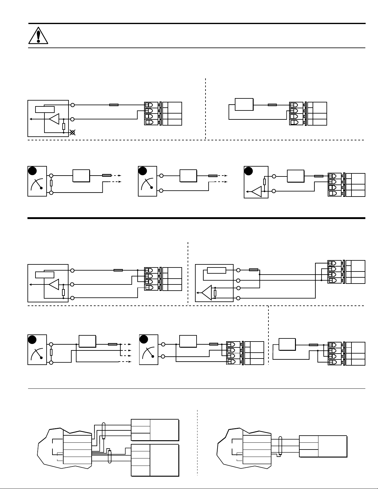
1. Loop/System Power Connections
1.1 2-Wire operation (for OMEGA FP-5200, FP-5300, FP-6000, FP-850X flow sensors).
A. Ground referenced PLC with internal transmitter power supply
PLC
4-20 mA Input
+
24 VDC
-
250Ω
C. 1 to 5 VDC recorder (C1), 4 to 20 mA indicator (C2), or ground referenced PLC (C3) connections without internal transmitter power supply
Recorder
1-5 VDC
C1
*
Refer to maximum loop impedance specification for minimum operating voltage requirements (section 10).
**1/8A fuse recommended (customer supplied)
1.2 3-Wire operation (for OMEGA FP-2541 flow sensors). This wiring is required for powered flow sensors that consume more than 1.5 mA DC current.
A. Ground referenced PLC with internal transmitter power supply
CH (gnd)
250Ω
CH +
PLC
4-20 mA Input
+
24 VDC
-
250Ω
*
*
-
*
Power out
CH +
CH - (gnd)
Power
supply
24
*
VDC
Power out
CH +
CH - (gnd)
Fuse**
1/8A
Fuse**
1/8A
+
Fuse**
1/4A
Indicator
4-20 mA
C2
FP85A
+
+
CH (gnd)
CH +
FP85A
+
+
-
-
-
-
4-20 mA
Loop
17-30V
Gnd
4-20 mA
Loop
17-30V
Gnd
*
Power
supply
-
24
VDC*
Fuse**
1/8A
+
B. Differential input PLC with internal transmitter power supply
4-20 mA Input
-
*
B. Power connection for display use only
Power
PLC
24 VDC
-
+
+
supply
24
*
VDC
4-20 mA Input
C3
Fuse**
PLC
250Ω
1/4A
Fuse**
1/8A
+
CH (gnd)
*
CH +
-
CH +
250Ω*
CH -
Power
supply
-
24*
VDC
FP85A
+
-
+
+
4-20 mA
Loop
17-30V
Gnd
-
Fuse**
1/8A
*
FP85A
FP85A
+
+
+
+
-
-
-
-
4-20 mA
Loop
17-30V
Gnd
4-20 mA
Loop
17-30V
Gnd
*
*
C. 1 to 5 VDC recorder (C1) and 4 to 20 mA indicator (C2) connections without internal transmitter
power supply
Recorder
1-5 VDC
C1
*
Refer to maximum loop impedance specification for minimum operating voltage requirements (section 10).
**1/4 A fuse recommended (customer supplied).
CH (gnd)
250Ω
CH +
Power
supply
-
24
VDC
Fuse**
1/4A
+
*
*
Indicator
4 -20 mA
C2
CH (gnd)
CH +
Power
supply
-
VDC
24
Fuse**
1/4A
+
*
FP85A
+
-
+
-
4-20 mA
Loop
17-30V
Gnd
2. Compatible Sensor Connections
2.1 2-Wire Operation (sec. 1.1) 2.2 3-Wire Operation (sec. 1.2)
FP85A
SENSOR
Frequency In
Sensor Power
Gnd
Frequency In
OPEN
COLLECTOR
SENSOR
STANDARD
OMEGA Flow Sensors:
Red
Black
Shld
OR
Shld
Black
Red
FP8501A
FP8502A
FP8503A
FP5100,
FP-5200,
FP-5300,
FP-6000,
FP-8501A
OPEN
COLLECTOR
SENSOR
STANDARD
SENSOR
FP85A
Frequency In
Sensor Power
Frequency In
D. Power connection for display use only
Power
*
Gnd
-
supply
24
VDC
Fuse**
1/4A
+
*
OMEGA Flow Sensor:
Red
Black
Shld
FP-2541
FP85A
+
-
+
-
4-20 mA
Loop
17-30V
Gnd
*
Page 2

3. Pulse Output Wiring
FP85A
FP85A
10 kΩ
+
5 to 30
VDC
-
Pulse Gnd
Pulse Out
Shld
Red
Receiving
instrument
4. Installation Options
4.1 Standard Panel Mount
• Panel cutout template/instructions (included).
®
Instrument
Panel
panel
Panel
FP85-A Flow Transmitter
4.2 Optional FP85UNM Universal Mounting Kit
• NPT and DIN conduit port kits available (see section 4.3).
• See section 9 for ordering options.
Pipe Pipe
Gnd.
Input
Other
instrument
Pulse Gnd
Pulse Out
4.3 Optional FP85NM Integral Mounting Kit
• NPT and DIN conduit port kits available.
• Compatible with FP850X flow sensors (only).
• Flow sensor and fitting purchased separately (see section 9).
Conduit ports
Conduit Port Options
DIN Ports
NPT Ports
®
FP85-A Flow Transmitter
5. FUNCTIONS
VIEW
CALIBRATE
OPTIONS
FP85-A Flow Transmitter
Press &
hold for
access:
®
2s 5s
Blind holes
for DIN conduit
connectors (8)
PG13.5 metric
threaded conduit
ports (2)
6. VIEW (example)
1
Choose:
E
↑
A.
B.
C.
Flow rate
2s
Resettable total
2s
Permanent tota
1/2 in. NPT
threaded conduit
ports (2)
Change:
OPTIONS =
1.
2.
2
Press and
hold 2s
OPTIONS =
1.
2.
3
Save:
Press keys in
sequence
Press and
l
To exit without
changes:
hold 2s
D.
Loop output
quick
press
3.
E.
Last cal.
A
↓
Page 3
Press keys in sequence to
1 2
To return to
VIEW:
quick
press
To restore original value:
Choose:
3
Save:
Change:
quick
press
Press keys in sequence to
continue:
2s
Press &
hold
VIEW= VIEW=Totalizer
low= τ=700 ms
hi= τ=3 s
off= 100 ms
Display
averging
Flow display
Output
Output
Decimal
postion
4 mA
adjust
20 mA
adjust
Return to
VIEW before
removing
power
A
↓
E
↑
continue:
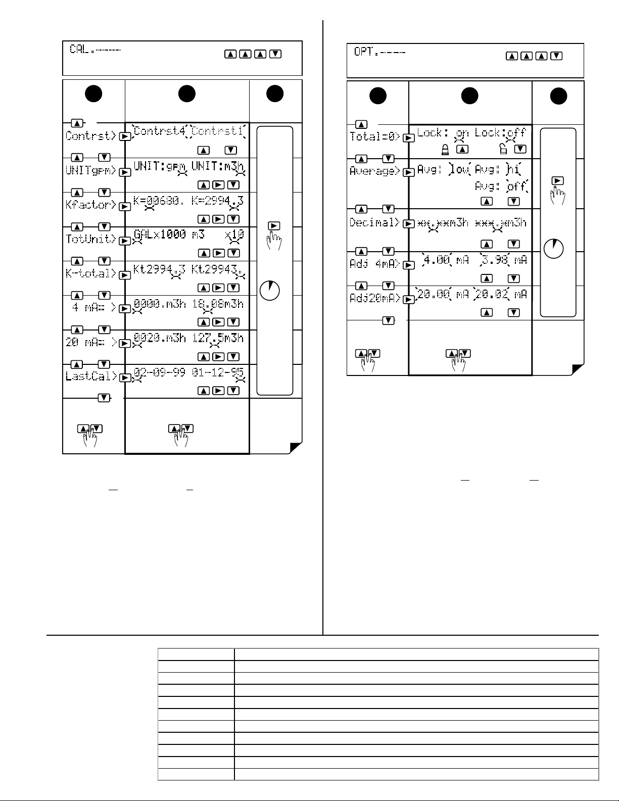
8. OPTIONS (example)7. CALIBRATE (example)
A.
B.
C.
D.
E.
F.
G.
H.
1 2
H
↑
Contrast
Flow
Flow
Totalizer
Totalizer
Output
Output
Last calibration
To return to
VIEW:
quick
press
Unit/timebase:
- label only -
A
↓
To restore original value:
h,m,s,d
K-factor
Units
K-factor
4 mA
setpoint
20 mA
setpoint
3
Change: Save:Choose:
A.
B.
C.
quick
press
Press &
hold
2s
Return to
VIEW before
removing
power
D.
E.
Menu Functions A - H:
A. Selects display contrast: 4 levels
B. Sets flow units (gpm) and timebase (gpm). Flow units label: Aa - Zz, 0 - 9;
Timebase options: s=seconds, m=minutes, h=hours, d=days (timebase
effects flow display and 4 to 20 mA output)
C. Sets flow K-factor: 000.01 to 99999. (see technical notes below)
D. Set totalizer units: For label purposes only
E. Sets totalizer K-factor: 000.01 to 99999. (see technical notes below)
F. Sets 4 mA setpoint (4 mA and 20 mA setpoints are reversible)
G. Sets 20 mA setpoint
H. Sets user defined date
Technical notes:
Flow and totalizer K-factors are independent of each other. These K-factors
represent the number of pulses generated by the flow sensor for each
engineering unit measured (published in flow sensor manual).
9. Accessories
Menu Functions A - E:
A. Selects totalizer reset options: Lock on (enables) or lock off (disables) the
VIEW menu totalizer reset security code feature (RST: -- -- -- --).
B. Selects display averaging: off = 100ms, low= τ=700ms, hi= τ=3s (also
affects 4 to 20 mA output).
C. Selects display decimal:
D. Adjusts 4 mA output: 3.9 to 4.1 mA (overrides 4.00 mA factory calibration)
E. Adjusts 20 mA output: 19.8 to 21.0 mA (overrides 20.00 mA factory
calibration)
****
. to ** .
**
Order no. Description
FP85UNM Universal mounting kit, NPT ports
FP85UDM Universal mounting kit, DIN ports
FP85NM Integral sensor mounting kit, NPT ports
FP85DM Integral sensor mounting kit, DIN ports
FP8501 Integral sensor, 0.5 to 4 inch pipe, Polypropylene body & Titanium rotor pin
FP8502 Integral sensor, 5 to 8 inch pipe, Polypropylene body & Titanium rotor pin
FP8503 Integral sensor, 0.5 to 4 inch pipe - PVDF body & Hastelloy C rotor pin
FP8501A Integral sensor, 0.5 to 4 inch pipe, Polypropylene body & Titanium rotor pin
FP8502A Integral sensor, 5 to 8 inch pipe - Polypropylene body & Titanium rotor pin
FP8503A Integral sensor, 0.5 to 4 inch pipe - PVDF body & Hastelloy C rotor pin
Page 4
10. Specifications
30 mm (1.2 in.)
36 mm (1.4 in.)
General Data
Compatible Sensors: FP-8501, FP-5300, FP-5100, FP-6000, and
FP-5200 Series (contact engineering for
additional compatible sensors).
Display Accuracy: Flow, ±0.1% of reading
Totalizers, ±0.03% of reading
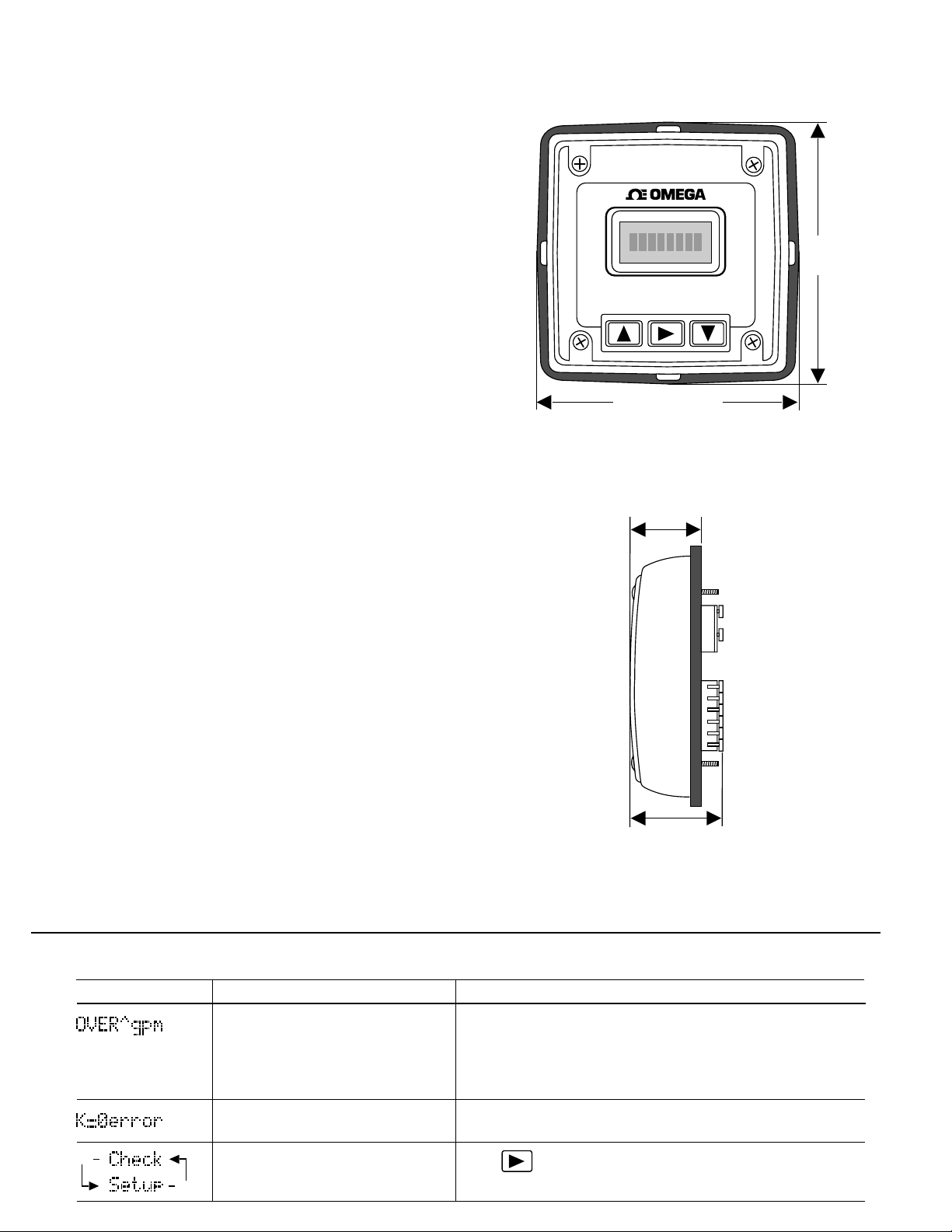
Dimensions:
Enclosure:
• Rating: NEMA 4X/IP65
• Material: Glass-filled polypropylene
• Gasket: Silicone rubber (captive)
• Screws: 8-32, self-tapping (captive)
Display:
• Type: 8-digit alphanumeric dot matrix
• Update rate: Flow=1s, Totalizers=100 mS
• Contrast: Variable
• Ranges: Flow, 0.01 to 9999.
Resettable/permanent totalizers, 0 to
99999999
Loop current, 3.90 to 21.00 mA
Environmental
Operating temperature: -15 to 70 °C (5 to 158 °F)
Storage temperature: -15 to 80 °C (5 to 176 °F)
Relative humidity: 0 to 95%, non-condensing
Agency Approvals
•CE
• Manufactured under ISO 9001
Electrical Data
Frequency range: 0.5 Hz to 500 Hz
Loop/system power: (2-wire mode) 17 to 30 VDC @ 20 mA max.
(3-wire mode) 17 to 30 VDC @ 68 mA max.
Sensor power: (2-wire mode) 5 VDC @ 1.5 mA max.
(3-wire mode) 5 VDC @ 20 mA max.
®
107 mm
(4.2 in.)
FP85A Flow Transmitter
107 mm (4.2 in.)
(front view)
Loop:
• Impedance: 1 Ω max. @ 17 VDC,
• Accuracy: ±0.050 mA
• Resolution: 5 µA
• Update rate: 100 ms
Outputs:
• Current: 4 to 20 mA (adjustable & reversible)
• Pulse output: Sensor frequency, optically isolated
300 Ω max. @ 24 VDC,
600 Ω max. @ 30 VDC
open-collector transistor, max. current sink
10 mA @ 30 VDC
11. Troubleshooting
Display Message Cause Solution
1) Input frequency too high
2) Display overrange
3) Display timebase too large
K-Factor cannot be zero
2s
Memory corrupted
2s
(side view)
1) Reduce input frequency.
2) Move display decimal to right in OPTIONS menu.
3) Change display timebase (H,M,S,D) to smaller value
(e.g. LPH to LPM).
Change K-Factor to a non-zero value.
Press to restore normal operation. Settings will revert to
factory default. Recalibration is required.
 Loading...