

Page 1
TM
NORWALK, CT
User’s Guide
Shop online at
omega.com
e-mail: [email protected]
For latest product manuals:
www.omegamanual.info
FP7002/FP7002A
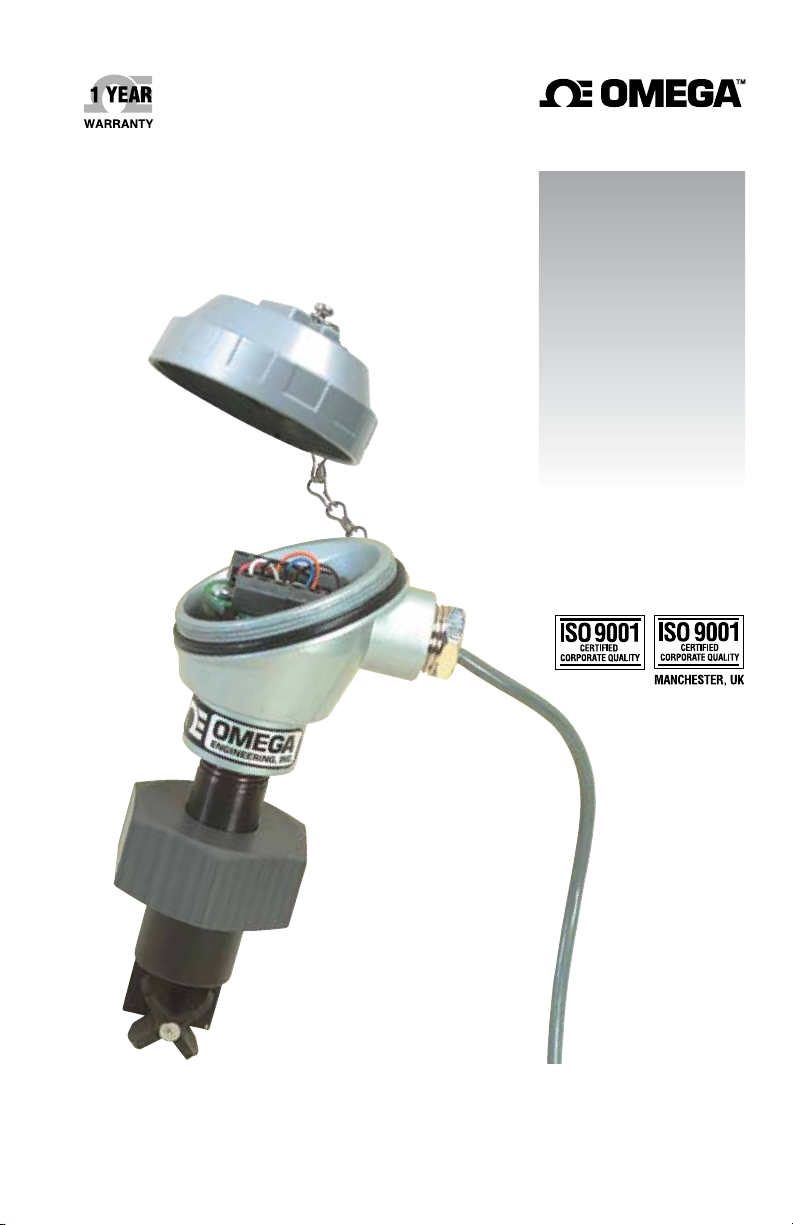
Flow/Temperature Transmitter
Page 2

omega.com [email protected]
Servicing North America:
U.S.A. Omega Engineering, Inc.
Headquarters: Toll-Free: 1-800-826-6342 (USA & Canada only)
Customer Service: 1-800-622-2378 (USA & Canada only)
Engineering Service: 1-800-872-9436 (USA & Canada only)
Tel: (203) 359-1660 Fax: (203) 359-7700
e-mail: [email protected]
For Other Locations Visit omega.com/worldwide
The information contained in this document is believed to be correct, but OMEGA accepts no liability for any errors it contains,
and reserves the right to alter specifications without notice.
Page 3

Table of
FP7002/FP7002A Flow/Temperature Transmitter
Contents
FP7002/FP7002A FLOW/TEMPERATURE TRANSMITTER
SECTION PAGE
Section 1 - General Description ......................... 1
Section 2 - Installation ................................. 1
2.1 Unpacking .............................................. 1
2.2 Important Considerations Before Installation ................ 1
2.3 Flowmeter Installation .................................... 2
2.4 Electrical Connections .................................... 4
Section 3 - Maintenance ................................ 5
Section 4 - Calibration ................................. 5
4.1 Flow Calibration ......................................... 5
4.2 Temperature Calibration .................................. 6
4.3 Calibration Setup ........................................ 7
Section 5 - Specifications ............................... 9
i
Page 4

FP7002/FP7002A Flow/Temperature Transmitter
Introduction/Safety
Your FP7002/FP7002A has been designed for ease of use and flexibility.
It is important that you read this user’s manual completely and follow
all safety precautions before operating your unit.
Precautions
1. FOLLOW ALL SAFETY PRECAUTIONS AND OPERATING
INSTRUCTIONS OUTLINED IN THIS MANUAL.
3. ADD ADDITIONAL SAFEGUARDS TO YOUR SYSTEM IN
CRITICAL APPLICATIONS WHERE DAMAGE OR INJURY
MAY RESULT FROM SENSOR FAILURE.
5. DO NOT OPERATE IN FLAMMABLE OR EXPLOSIVE
ENVIRONMENTS.
6. DO NOT USE IN HUMAN MEDICAL OR NUCLEAR
APPLICATIONS.
7. NEVER OPERATE WITH A POWER SOURCE OTHER THAN
WHAT IS SPECIFIED IN THIS MANUAL.
8. REMOVE AND/OR DISCONNECT POWER SOURCE BEFORE
ATTEMPTING INSTALLATION OR MAINTENANCE.
9. ALWAYS OPERATE YOUR UNIT WITH THE SHIELD WIRE
CONNECTED TO EARTH GROUND.
10. INSTALLATION AND WIRING SHOULD BE DONE BY
TRAINED PROFESSIONALS ONLY.
NOTE
There are no user serviceable parts inside your unit.
Attempting to open, repair or service your unit may void
your warranty.
ii
Page 5
FP7002/FP7002A Flow/Temperature Transmitter
Section 1 - General Description
The FP7002 flow/temperature transmitter is ideal for monitoring of
typical industrial water flows and temperature, from hard-to-handle
corrosive aqueous solutions to high purity fluids. The FP7002 uses a
paddlewheel-like rotor whose motion is converted into a pulse output.
This pulse output is converted to a 4 - 20 mA (or 1 - 5 Vdc) analog
output by the built-in signal conditioner. A solid state temperature
sensor built into the sensor body provides a separate 4 - 20 mA (or
1 - 5 Vdc) analog output directly proportional to changes in fluid
temperature. These independent analog outputs can be run long
distances to a panel meter, controller or computer.
A complete flow measurement system consists of the flow sensor/
transmitter, the installation fitting and a readout device. The FP7002
has polypropylene, 316SS, and FKM wetted parts. The schedule 40 PVC
tee fittings are supplied with a PVC locking nut, and the galvanized
iron tee fittings are supplied with a brass locking nut to provide a
secure metal to-metal mounting to the threaded brass insert.
Section 2 - Installation
2.1 Unpacking
Remove the Packing List and verify that you have received all
equipment. If you have any questions about the shipment, please call
the OMEGA Customer Service Department.
When you receive the shipment, inspect the container and equipment
for any signs of damage. Note any evidence of rough handling in
transit. Immediately report any damage to the shipping agent.
1
NOTE
The carrier will not honor any claims unless all shipping
material is saved for their examination. After examining
and removing contents, save packing material and carton
in the event that reshipment is necessary.
2.2 Important Considerations Before Installation
CAUTION
THE FP7002 PADDLEWHEEL FLOW TRANSMITTER IS NOT
EXPLOSION-PROOF, NOR IS IT INTRINSICALLY SAFE. IT
IS NOT TO BE USED FOR FLAMMABLE OR HAZARDOUS
LIQUIDS, NOR CAN IT BE USED IN HAZARDOUS AREAS.
The FP7002 is intended for use with water and other low viscosity
liquids ONLY; it can NOT be used with oils and other viscous
1
Page 6

2
FP7002/FP7002A Flow/Temperature Transmitter
materials. It can be used with non-flammable, non-hazardous liquids
up to 5 centipoise viscosity, but field calibration is recommended for
accurate measurements.
It is important to note that most process water contains dissolved
minerals. If the flowsensor is repeatedly exposed to process water and
then the line is allowed to dry, these dissolved minerals will deposit
onto the FP7002 and will inhibit the low flowrate operation of the
sensor. If this occurs, cleaning of the sensor is recommended.
CAUTION
WATER HAMMER AND SURGES CAN BE DAMAGING TO
ANY FLOWMETER AND MUST ALWAYS BE AVOIDED.
WATER HAMMER OCCURS WHEN A LIQUID FLOW IS
SUDDENLY STOPPED AS WITH QUICK CLOSING AND
SOLENOID OPERATED VALVES. SURGES OCCUR WHEN
FLOW IS SUDDENLY BEGUN, AS WHEN A PUMP IS
TURNED ON AT FULL POWER OR A VALVE IS QUICKLY
OPENED.
LIQUID SURGES ARE PARTICULARLY DAMAGING TO
FLOWMETERS IF THE PIPE IS ORIGINALLY EMPTY. TO
AVOID DAMAGING SURGES, FLUID LINES SHOULD
REMAIN FULL (IF POSSIBLE) AND PUMPS SHOULD
BE BROUGHT UP TO POWER AND VALVES OPENED
SLOWLY. IN ADDITION, TO AVOID BOTH WATER
HAMMER AND SURGES, A SURGE CHAMBER SHOULD
BE INSTALLED.
2.3 Flowmeter Installation
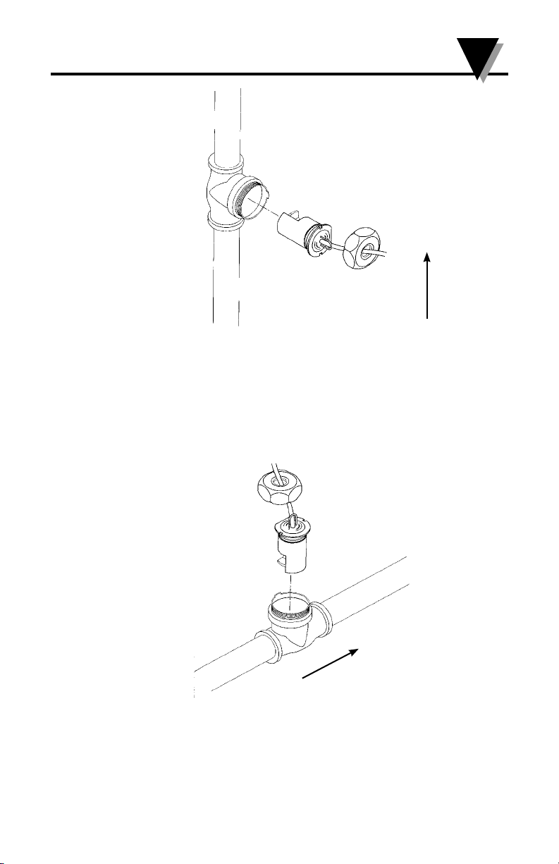
The FP7002 can be mounted in vertical or horizontal pipe runs;
however, the pipe must be full of liquid for proper readings. Thus, the
sensor should not be mounted in vertical pipe where the liquid flows
down, since the pipe may not always be full in this situation. Refer to
Figures 2-1 and 2-2.
2
Page 7
FP7002/FP7002A Flow/Temperature Transmitter
Figure 2-1. Horizontal Mounting Position
2
FLOW
FLOW
Figure 2-2. Vertical Mounting Position
3
Page 8
2
FP7002/FP7002A Flow/Temperature Transmitter
The FP7002 should not be mounted at the bottom of the pipe (the 6
o’clock position) because this is where sediment in the liquid will tend
to accumulate. The best mounting location is at or near the 12 o’clock
position, so long as bubbles are not present in the liquid. The 3 o’clock
and 9 o’clock positions are also acceptable. In an upward flowing
vertical pipe, the flowsensor can be mounted anywhere around the
pipe.
As with many flowmeters, the FP7002 requires a fully developed
flow profile in order to provide accurate readings. To insure this, a
length of straight pipe run before and after the flowmeter is required.
The amount of upstream straight pipe run that is required depends
upon the type of obstruction which is immediately upstream of the
flowsensor. See Table 2-1 for specific requirements. Downstream of the
flowsensor, in all situations, only 5 diameters of straight pipe run is
required, regardless of the downstream obstruction.
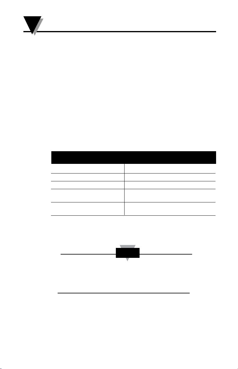
Table 2-1
UPSTREAM
OBSTRUCTION
Concentric reducer 15 pipe diameters
One elbow 20 pipe diameters
2 elbows, in same plane 25 pipe diameters
2 elbows, in two planes, 40 pipe diameters
or one expansion
Valves, pumps*, same plane at least 50 pipe diameters, prefer sensor
mounted upstream
STRAIGHT PIPE RUN REQUIRED
UPSTREAM OF PADDLEWHEEL SENSOR
*Oscillating or reciprocating pumps, which produce flow and pressure
pulses in the flowstream, are not recommended for use with the FP7002
flowsensor.
NOTE
If you do not have the proper amount of straight pipe
run available at your desired installation location, it is
recommended to use flow straighteners to decrease the
required straight run.
The paddlewheel must be aligned with the fluid flow; the installation
fitting is supplied with an alignment tab which mates with a flat on
the base of the paddlewheel sensor to insure proper sensor alignment.
When using the PVC installation fitting, it is critical that the cap of the
sensor is threaded onto the mating fitting HAND TIGHT ONLY; use
of pipe wrenches, etc. on the plastic cap can lead to damage to the cap
and/or the installation fitting.
4
Page 9
FP7002/FP7002A Flow/Temperature Transmitter
PANEL METER
The FP7002 has magnets installed in the rotating paddles; these
magnets will tend to attract rust from the flowing fluid. Thus, it is
NOT recommended to install the FP7002 in pipes which under typical
conditions contain rust, such as in cast iron, black iron, carbon steel
and other iron pipes (galvanized pipe has been treated to resist rust). In
situations where rust can not be avoided, it is recommended to install a
fine magnetic filter at least 50 pipe diameters upstream from the FP7002
and to periodically shut down the line and remove the sensor from the
installation fitting for cleaning.
2.4 Electrical Connections
CAUTION
All electrical connections and wiring should be performed
by suitably trained personnel only.
NOTE
To insure proper hook-up to your indicating device, the
paddles of the FP7002 can be spun in the open air by
blowing onto them before the sensor is installed into the
installation fitting.
This is particularly important where the pipeline can not
be conveniently shut down and the sensor removed after
installation.
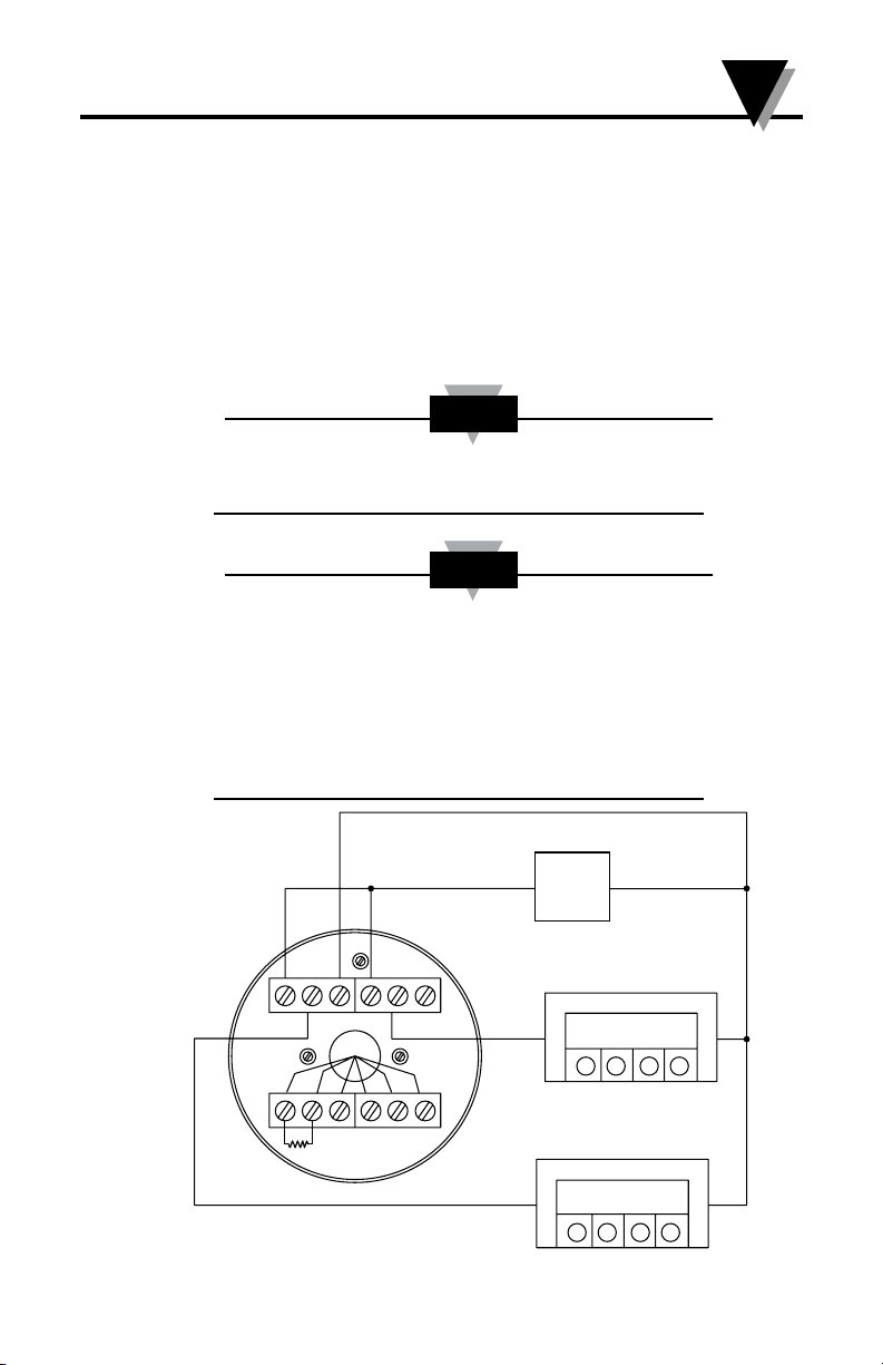
2
TB6
TB1
P3
1
P1
6
54 3261
10 K RESISTOR
5432
TB3
P2
TB4
Figure 2-3. Basic Wiring Diagram
+
+
18 Vdc
PWR
+
–
23.0 C
PANEL METER
200 GPM
–
–
5
Page 10

3
FP7002/FP7002A Flow/Temperature Transmitter
Section 3 - Maintenance
Except for intermittent removal of the sensor from the flow line for
cleaning, there is no routine maintenance for the FP7002.
Section 4 - Calibration
4.1 Flow Calibration
Equipment Required:
12-18 Vdc Regulated Power Supply
Frequency Generator/Calibrator (such as OMEGA Model: CL123)
Multimeter (such as OMEGA Model: HHM290)
Small jeweler’s type common blade screwdriver
Calibration Procedure:
1. Unscrew and remove the protection head cover.
2. Make wiring connections to the transmitter as shown on page 7.
3. Apply power and allow the unit to warm up for 10 minutes.
4. Determine the maximum volumetric flow rate expected by the
application.
For our example we will use “GPM”. This will be “GPM Max”
5. From the table on page 8, determine the proper “K-Factor” for the
model fitting you will be using.
6. Determine your full scale calibration frequency using this formula.
This will be “F Max”.
Example: Using a Model FP7015 Tee Fitting with a K-Factor of 29.46
and a GPM Max of 125.
29.46 x 125 GPM = 61.38 for your F Max
60
7. Set your frequency generator for an output of 0 Hz. Adjust the zero
potentiometer (P1) for a 4.00 mA output.
8. Set your frequency generator for the “F Max” you calculated above.
Adjust the span potentiometer (P2) for a 20.00 mA output.
9. Set your frequency generator for one half the “F Max” you calculated
above. You should have an output reading of 12.00 mA +/- 0.16 mA.
If not, repeat steps 7 & 8.
10. Re-install 10 k resistor across terminals 5 and 6 and re-install white
wire to terminal 5.
11. Calibration complete.
F Max = K-Factor x GPM Max
60
6
Page 11

FP7002/FP7002A Flow/Temperature Transmitter
Section 4 - Calibration Cont.
4.2 Temperature Calibration
Equipment Required:
12-18 Vdc Regulated Power Supply
Type-K Thermocouple Probe (such as OMEGA Model: KTSS-HH)
Multimeter (such as OMEGA Model: HHM290)
Small potentiometer adjustment tool
Calibration Procedure:
1. Unscrew and remove the protection head cover.
2. Make wiring connections to the transmitter as shown on page 7.
3. Apply power and allow the unit to warm up for 10 minutes.
4. Place a reference temperature probe next to the body of the
paddlewheel flow sensor with the unit removed from the flow line
and lying on a work bench.
5. Connect the reference probe to a thermometer and allow the reading
to stabilize for a few minutes. Record the reference probe reading as
“Rtemp”
6. Calculate the correct current output that the transmitter should have
for the ambient temperature your flow sensor and reference probe
are exposed to using this formula.
0.16 x Rtemp + 4 = output setting
Example: If your reference probe is reading 23.4°C
0.16 x 23.4 + 4 = 7.74 mA
7. Adjust potentiometer P3 for the correct current output you calculated
above.
8. Calibration complete.
4
7
Page 12
4
FP7002/FP7002A Flow/Temperature Transmitter
Section - Calibration Cont.
4.3 Calibration Setup
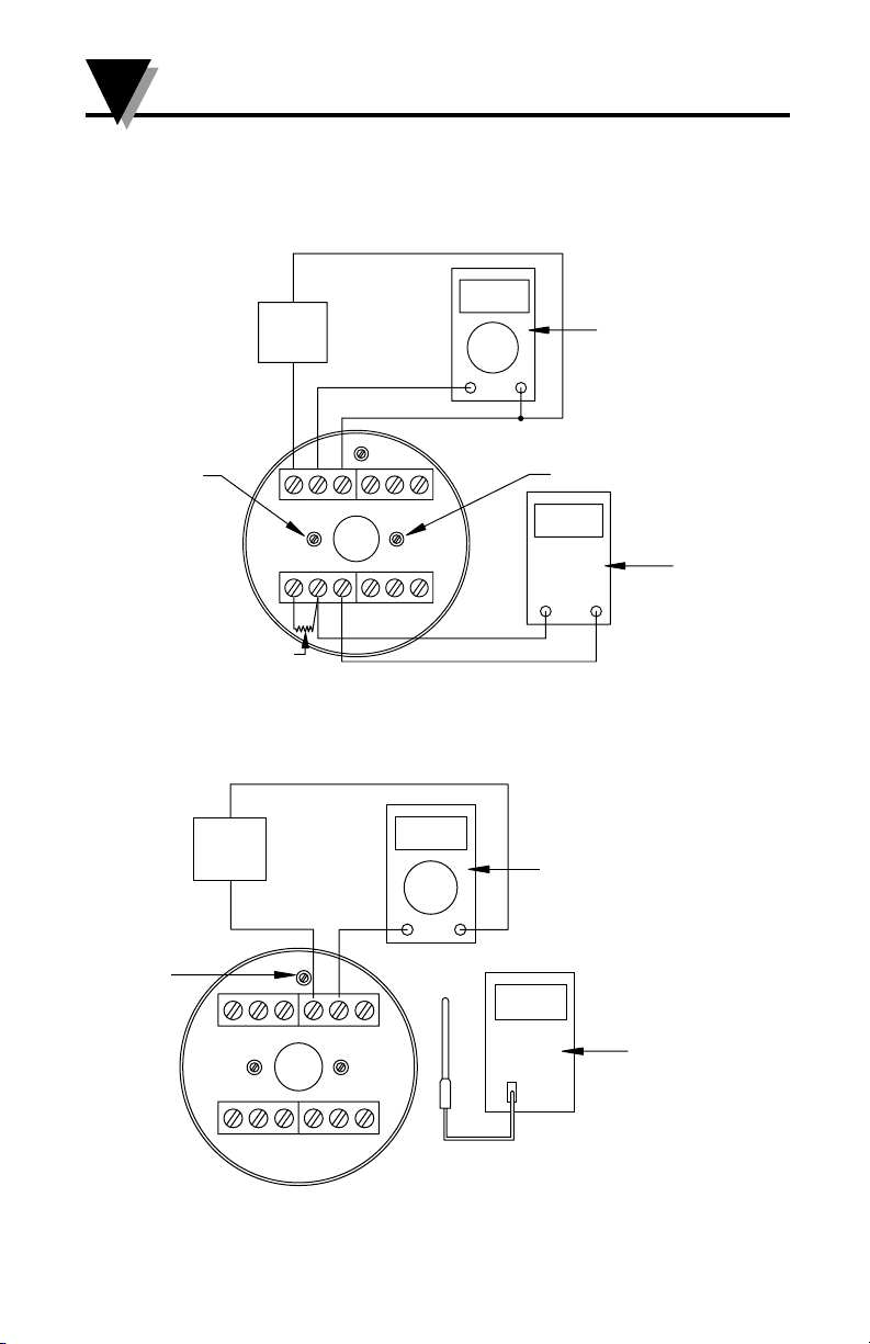
4.3.1 Flow Calibration Setup
18 Vdc
MAX
PWR
+
P1
TB6
TB1
REMOVE RESISTOR
AND WHITE WIRE
FOR CALIBRATION
1 2 3 4 5 6
TB3
1 5 4 3 2 6
TB4
Figure 4-1. Flow Calibration Setup
4.3.2 Temperature Calibration Setup
–
18 Vdc
MAX
PWR
+
7.85 mA
+
–
4.00 mA
+
–
P2
0.00 Hz
+
MULTIMETER
MULTIMETER
–
FREQUENCY
GENERATOR
P3
TB6
TB1
1
6
54 3
5432
6
TB3
1
2
TB4
23.0
C
THERMOMETER
Figure 4-2. Temperature Calibration Setup
8
Page 13
FP7002/FP7002A Flow/Temperature Transmitter
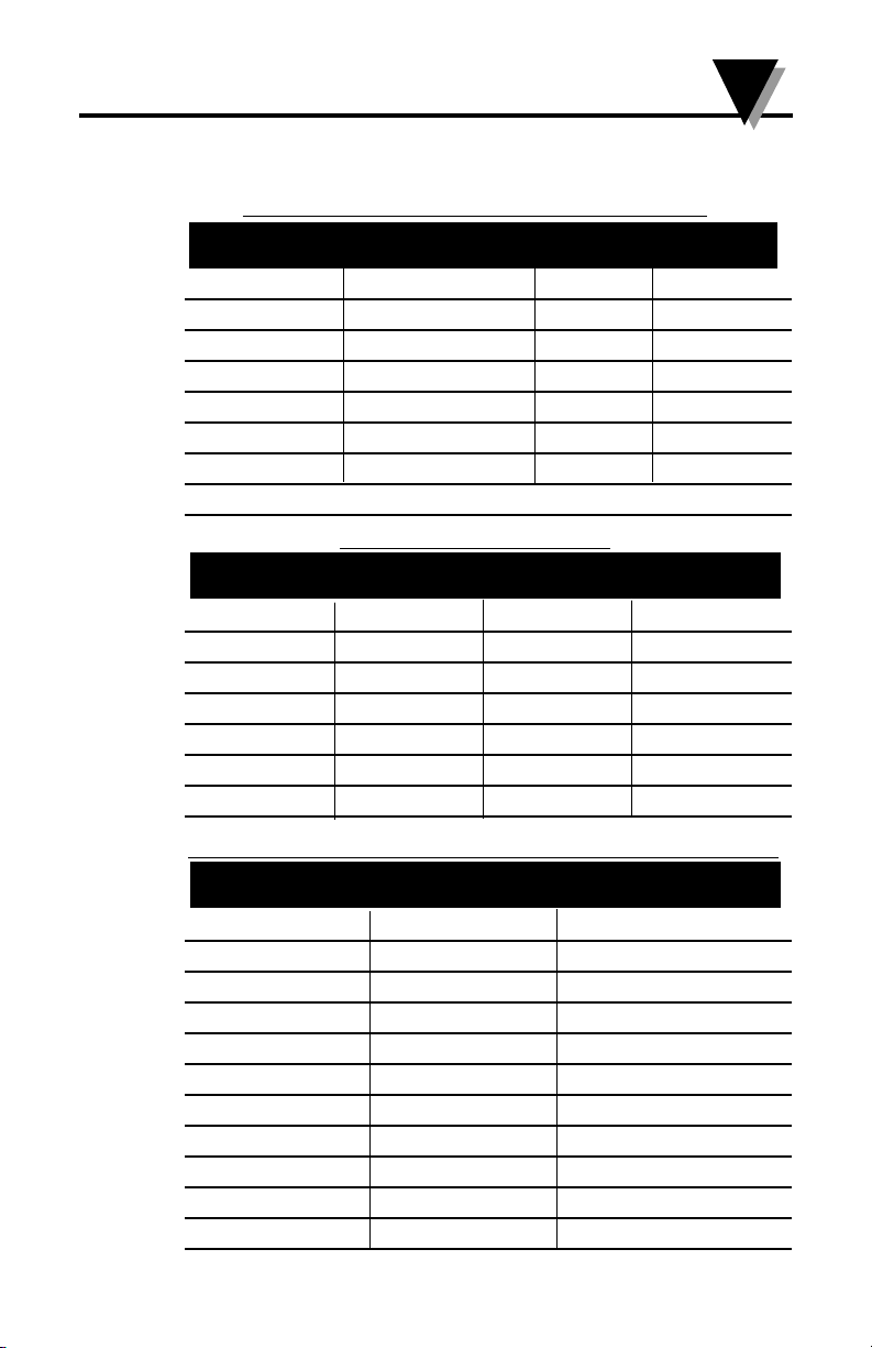
Sensor/Transmitter
FP7002 Polypropylene body/316SS shaft
INSTALLATION FITTINGS (includes locking nut)
PVC, SCHED. 40 GALVANIZED IRON PIPE RANGE
(PART NUMBER) (PART NUMBER) SIZE (GPM)
FP7007 FP7007-GI
3
⁄4” 2-30
FP7010 FP7010-GI 1” 3-50
FP7012 FP7012-GI 11⁄4” 5-90
FP7015 FP7015-GI 11⁄2” 7-125
FP7020 FP7020-GI 2” 11-205
FP7025 FP7025-GI 21⁄2” 15-285
FP7030 FP7030-GI 3” 25-460
Other fitting materials may be available. Consult the Flow Department at OMEGA.
CALIBRATION K-FACTORS
PART NUMBER K-FACTOR ART NUMBER K-FACTOR
FP7007 108.78 FP7007-GI 159.85
FP7010 70.53 FP7010-GI 82.94
FP7012 41.16 FP7012-GI 48.81
FP7015 29.46 FP7015-GI 35.52
FP7020 15.52 FP7020-GI 20.62
FP7025 11.40 FP7025-GI 12.44
FP7030 6.64 FP7030-GI 7.22
4
VISCOSITY and SURFACE TENSION of VARIOUS LIQUIDS at 293 K
COMMON LIQUID VISCOSITY/cP SURFACE TENSIO/N m
Diethyl ether 0.233 0.0728
Chloroform 0.580 0.0271
Benzene 0.652 0.0289
Carbon tetracholoride 0.969 0.0270
Water 1.002 0.0728
Ethanol 1.200 0.0228
Mercury 1.554 0.4360
Olive oil 84 _
Castor oil 986 –
Glycerol 1490 0.634
Glasses very large –
-1
9
Page 14

5
FP7002/FP7002A Flow/Temperature Transmitter
Section 5 - Specifications
Flow Transmitter
Accuracy: ± 2% of full scale
Repeatability: ± 1% of full scale
Power: Regulated 9 to 18 Vdc @ 50 mA max
Input: DC Pulse from Paddlewheel
Output: 3-Wire 4 to 20 mA or 1 to 5 Vdc
Max Loop Resistance: Ohms = (V supply - 9 V)/0.02 A
Temperature Transmitter
Accuracy: ± 1.7°C (3°F)
Repeatability: ± 0.2°C (0.4°F)
Range: 0 to 100°C (32 to 212°F)
Power: Regulated 9 to 18 Vdc @ 30 mA max
Output: 2-Wire 4 to 20 mA or 1 to 5 Vdc
Max Loop Resistance: Ohms = (V supply - 9 V)/0.02 A
General
NON-WETTED MATERIALS
Transmitter Housing: NEMA Rated - Painted Cast Aluminum
WETTED MATERIALS
Sensor Body: Polypropylene body (PVDF optional),
MAX, RECOMMENDED
FLUID VISCOSITY: 5 centipoise
FLUID TEMPERATURE/ Do not exceed the maximum ratings of
PRESSURE RANGE: your piping. Depending on the material
PVDF paddle, Viton O-ring, 316SS shaft.
Model FP7002A includes brass locking
nut. Model FP7002 includes PVC locking
nut.
of the fitting, the operating temperature/
pressure may be limited by your piping,
and not by the sensor. For all PVC tee
fittings, do not exceed 150 psig @ 27°C
(80°F), 100 psig @ 38°C (100°F), 60 psig @
49°C (120°F), 30 psig @ 60°C (140°F), due
to the insert in the tee. FP7000 sensor: 0°
to 26°C (32° to 80°F) up to 150 psig; max
pressure decreases 1.1 psig per each 1°F
about 80°F for a max. temperature of
200°F at 18 psig max.
10
Page 15

WARRANTY/DISCLAIMER
OMEGA ENGINEERING, INC. warrants this unit to be free of defects in materials and
workmanship for a period of 13 months from date of purchase. OMEGA’s WARRANTY adds
an additional one (1) month grace period to the normal one (1) year product warranty to
cover handling and shipping time. This ensures that OMEGA’s customers receive maximum
coverage on each product.
If the unit malfunctions, it must be returned to the factory for evaluation. OMEGA’s Customer
Service Department will issue an Authorized Return (AR) number immediately upon phone
or written request. Upon examination by OMEGA, if the unit is found to be defective, it
will be repaired or replaced at no charge. OMEGA’s WARRANTY does not apply to defects
resulting from any action of the purchaser, including but not limited to mishandling, improper
interfacing, operation outside of design limits, improper repair, or unauthorized modification.
This WARRANTY is VOID if the unit shows evidence of having been tampered with or shows
evidence of having been damaged as a result of excessive corrosion; or current, heat, moisture
or vibration; improper specification; misapplication; misuse or other operating conditions
outside of OMEGA’s control. Components in which wear is not warranted, include but are not
limited to contact points, fuses, and triacs.
OMEGA is pleased to offer suggestions on the use of its various products. However,
OMEGA neither assumes responsibility for any omissions or errors nor assumes
liability for any damages that result from the use of its products in accordance
with information provided by OMEGA, either verbal or written. OMEGA warrants
only that the parts manufactured by the company will be as specified and free of
defects. OMEGA MAKES NO OTHER WARRANTIES OR REPRESENTATIONS OF ANY
KIND WHATSOEVER, EXPRESSED OR IMPLIED, EXCEPT THAT OF TITLE, AND ALL
IMPLIED WARRANTIES INCLUDING ANY WARRANTY OF MERCHANTABILITY AND
FITNESS FOR A PARTICULAR PURPOSE ARE HEREBY DISCLAIMED. LIMITATION
OF LIABILITY: The remedies of purchaser set forth herein are exclusive, and the
total liability of OMEGA with respect to this order, whether based on contract,
warranty, negligence, indemnification, strict liability or otherwise, shall not exceed
the purchase price of the component upon which liability is based. In no event shall
OMEGA be liable for consequential, incidental or special damages.
CONDITIONS: Equipment sold by OMEGA is not intended to be used, nor shall it be used: (1)
as a “Basic Component” under 10 CFR 21 (NRC), used in or with any nuclear installation or
activity; or (2) in medical applications or used on humans. Should any Product(s) be used in or
with any nuclear installation or activity, medical application, used on humans, or misused in
any way, OMEGA assumes no responsibility as set forth in our basic WARRANTY / DISCLAIMER
language, and, additionally, purchaser will indemnify OMEGA and hold OMEGA harmless from
any liability or damage whatsoever arising out of the use of the Product(s) in such a manner.
Direct all warranty and repair requests/inquiries to the OMEGA Customer Service Department.
RETURN REQUESTS/INQUIRIES
BEFORE RETURNING ANY PRODUCT(S) TO OMEGA, PURCHASER MUST OBTAIN AN
AUTHORIZED RETURN (AR) NUMBER FROM OMEGA’S CUSTOMER SERVICE DEPARTMENT
(IN ORDER TO AVOID PROCESSING DELAYS). The assigned AR number should then be
marked on the outside of the return package and on any correspondence.
The purchaser is responsible for shipping charges, freight, insurance and proper packaging to
prevent breakage in transit.
FOR WARRANTY RETURNS, please have
the following information available BEFORE
contacting OMEGA:
1. Purchase Order number under which
the product was PURCHASED,
2. Model and serial number of the product
under warranty, and
3. Repair instructions and/or specific
problems relative to the product.
OMEGA’s policy is to make running changes, not model changes, whenever an improvement is possible.
This affords our customers the latest in technology and engineering.
OMEGA is a trademark of OMEGA ENGINEERING, INC.
© Copyright 2018 OMEGA ENGINEERING, INC. All rights reserved. This document may not be copied, photocopied,
reproduced, translated, or reduced to any electronic medium or machine-readable form, in whole or in part, without
the prior written consent of OMEGA ENGINEERING, INC.
FOR NON-WARRANTY REPAIRS,
consult
OMEGA for current repair charges. Have the
following information available BEFORE
contacting OMEGA:
1. Purchase Order number to cover the
COST of the repair,
2. Model and serial number of the product, and
3. Repair instructions and/or specific problems
relative to the product.
Page 16

Where Do I Find Everything I Need for
Process Measurement and Control?
OMEGA…Of Course!
Shop online at omega.com
TEMPERATURE
MU
Thermocouple, RTD & Thermistor Probes, Connectors, Panels & Assemblies
MU
Wire: Thermocouple, RTD & Thermistor
MU
Calibrators & Ice Point References
MU
Recorders, Controllers & Process Monitors
MU
Infrared Pyrometers
PRESSURE, STRAIN AND FORCE
MU
Transducers & Strain Gages
MU
Load Cells & Pressure Gages
MU
Displacement Transducers
MU
Instrumentation & Accessories
FLOW/LEVEL
MU
Rotameters, Gas Mass Flowmeters & Flow Computers
MU
Air Velocity Indicators
MU
Turbine/Paddlewheel Systems
MU
Totalizers & Batch Controllers
pH/CONDUCTIVITY
MU
pH Electrodes, Testers & Accessories
MU
Benchtop/Laboratory Meters
MU
Controllers, Calibrators, Simulators & Pumps
MU
Industrial pH & Conductivity Equipment
DATA ACQUISITION
MU
Communications-Based Acquisition Systems
MU
Data Logging Systems
MU
Wireless Sensors, Transmitters, & Receivers
MU
Signal Conditioners
MU
Data Acquisition Software
HEATERS
MU
Heating Cable
MU
Cartridge & Strip Heaters
MU
Immersion & Band Heaters
MU
Flexible Heaters
MU
Laboratory Heaters
ENVIRONMENTAL
MONITORING AND CONTROL
MU
Metering & Control Instrumentation
MU
Refractometers
MU
Pumps & Tubing
MU
Air, Soil & Water Monitors
MU
Industrial Water & Wastewater Treatment
MU
pH, Conductivity & Dissolved Oxygen Instruments
M4054/0118
 Loading...