

Page 1
User’s Guide
Shop online at
omega.com
e-mail: [email protected]
For latest product manuals:
omegamanual.info
FP6501/6502
FP6511/6512
FP6500 SERIES
Insertion Pa d d l ewheel Flow Sensor
Page 2

OMEGAnet®Online Service Internet e-mail
It is the policy of OMEGA Engineering, Inc. to comply with all worldwide safety and EMC/EMI
regulations that apply. OMEGA is constantly pursuing certification of its products to the European New
Approach Directives. OMEGA will add the CE mark to every appropriate device upon certification.
omega.com i n f o @ o m e g a . c o m
Servicing North America:
U.S.A.: One Omega Drive, P.O. Box 4047
ISO 9001 Certified
Stamford, CT 06907-0047
TEL: (203) 359-1660 FAX: (203) 359-7700
e-mail: [email protected]
Canada: 976 Bergar
Laval (Quebec) H7L 5A1, Canada
TEL: (514) 856-6928 FAX: (514) 856-6886
e-mail: [email protected]
For immediate technical or application assistance:
U.S.A. and Canada: Sales Service: 1-800-826-6342 / 1-800-TC-OMEGA
Customer Service: 1-800-622-2378 / 1-800-622-BEST
Engineering Service: 1-800-872-9436 / 1-800-USA-WHEN
TELEX: 996404 EASYLINK: 62968934 CABLE: OMEGA
Mexico: En Espan˜ ol: (001) 203-359-7803 e-mail: [email protected]
FAX: (001) 203-359-7807 [email protected]
®
®
®
Servicing Europe:
Benelux: Postbus 8034, 1180 LA Amstelveen, The Netherlands
TEL: +31 (0)20 3472121 FAX: +31 (0)20 6434643
Toll Free in Benelux: 0800 0993344
e-mail: [email protected]
Czech Republic: Frystatska 184, 733 01 Karviná, Czech Republic
France: 11, rue Jacques Cartier, 78280 Guyancourt, France
TEL: +33 (0)1 61 37 2900 FAX: +33 (0)1 30 57 5427
Toll Free in France: 0800 466 342
e-mail: [email protected]
Germany/Austria: Daimlerstrasse 26, D-75392 Deckenpfronn, Germany
TEL: +49 (0)7056 9398-0 FAX: +49 (0)7056 9398-29
Toll Free in Germany: 0800 639 7678
e-mail: [email protected]
United Kingdom: One Omega Drive, River Bend Technology Centre
ISO 9002 Certified
Northbank, Irlam, Manchester
M44 5BD United Kingdom
TEL: +44 (0)161 777 6611 FAX: +44 (0)161 777 6622
Toll Free in United Kingdom: 0800-488-488
e-mail: [email protected]
The information contained in this document is believed to be correct, but OMEGA accepts no liability for any
errors it contains, and reserves the right to alter specifications without notice.
WARNING: These products are not designed for use in, and should not be used for, human applications.
Page 3

TABLE OF CONTENTS
General Information
General Information, Features, Specications .................................................................................................Page 1
Installation
Piping, Positioning the Meter, Immersion, Depth Setting ................................................................................ Page 2
Installation .......................................................................................................................................................... Page 3
Dimension C, Pipe Wall Thickness .................................................................................................................... Page 4
Flow Rate, K-Factors .......................................................................................................................................... Page 5
Straight Pipe Recommendations ......................................................................................................................
Full Pipe Recommendations ..............................................................................................................................Page 7
Connection, Operation & Repair
Calibration, Theory of Operation, Flow Range, Rotor Replacement ...............................................................Page 8
Repair & Parts
Signal, Parts Explosion, Parts List .................................................................................................................... Page 9
Troubleshooting
Problem, Probable Cause, To Try....................................................................................................................... Page 10
TABLES AND DIAGRAMS
Page 6
Features .............................................................................................................................................................. Page 1
Specications Table ...........................................................................................................................................Page 1
Piping .................................................................................................................................................................. Page 2
Positioning the Meter ......................................................................................................................................... Page 2
Depth Setting ..................................................................................................................................................... Page 2
Meter Installation ............................................................................................................................................... Page 3
Table 1 (Dimension 'C') ...................................................................................................................................... Page 4
Table 2 (Pipe Wall Thinkness) ........................................................................................................................... Page 4
Table 3 (Flow Rate) ............................................................................................................................................ Page 5
Table 4 (K Factors) ............................................................................................................................................. Page 5
Straight Pipe Recommendations ......................................................................................................................
Full Pipe Recommendations ..............................................................................................................................Page 7
Connection Diagram .......................................................................................................................................... Page 8
Page 6
Rotor Replacement ............................................................................................................................................Page 8
Parts Explosion ................................................................................................................................................... Page 9
Parts List ............................................................................................................................................................. Page 9
Troubleshooting: Problem, Probable Cause, To Try .......................................................................................... Page 10
Page 4
GENERAL INFORMATION
GENERAL INFORMATION
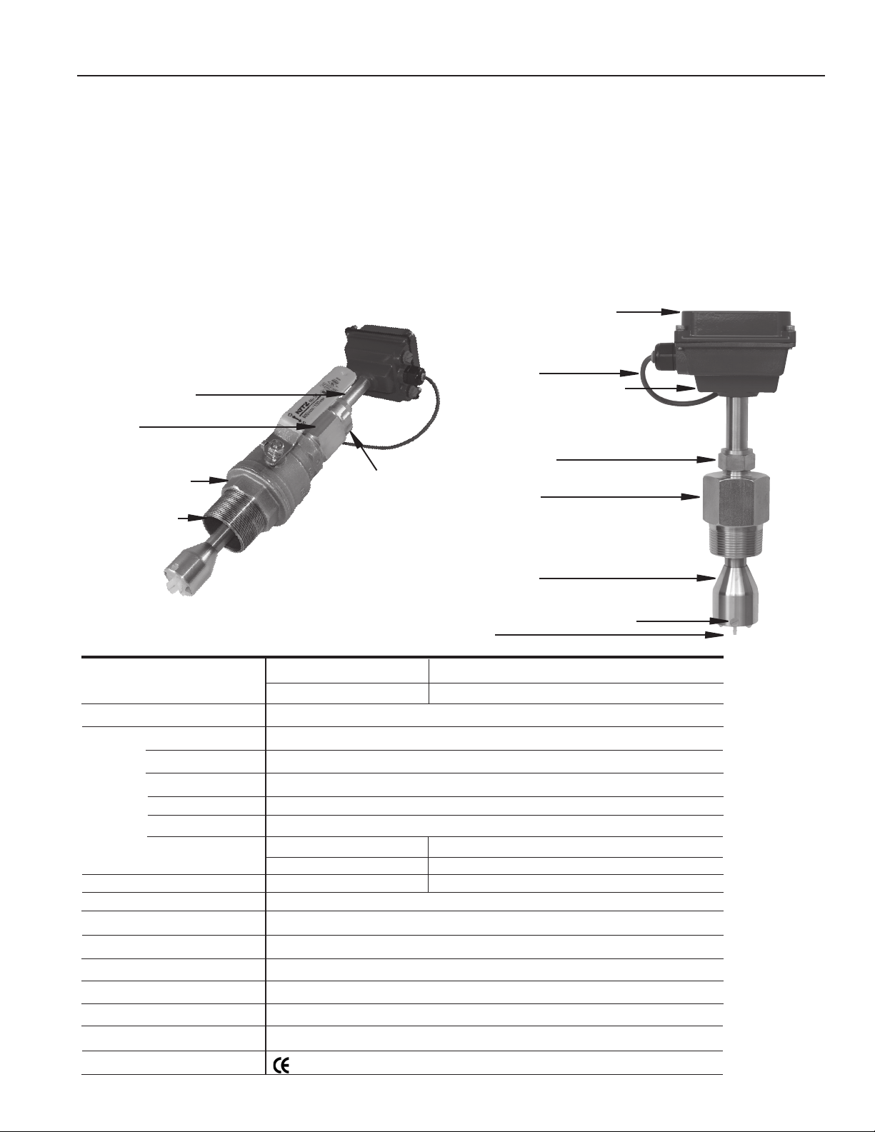
The FP6500 Series are adjustable depth insertion paddlewheels
that come in brass or 316 stainless models to t 3” to 40” pipe.
Installation ttings are standard 1-1/2" or 2” NPT. Fittings such
as saddles and weldolets may be purchased either locally or
from Omega.
Ruby bearings and a non-drag Hall-effect sensor give these meters
the widest ow range of any of the paddlewheel types. A sensor detects the passage of miniature magnets in the six rotor blades.
feet over unshielded cable without a transmitter and connected
directly to many PLC’s and other controls without any additional
electronics.
If desired, a modular system of electronics can be installed
directly on the ow sensor or mounted remotely.
The “hot-tap” models (FP6511/6512) can be installed or serviced
without shutting down the line by means of a 2” full-port isolation
valve that comes with a nipple for installation on the pipe tting.
In most circumstances, no special tool is required.
The resulting square-wave signal can be sent for hundreds of
FEATURES
3/4” diameter tubing
for low insertion force
2” Adapter
removes to mount
hot-tap machine
Full-port 2” ball valve
for sensor removal
Adapter tting with
2” NPT threads
FP6511/6512
(Add -SS for stainless)
Locking collar
Modular electronics (optional)
• rate/total/pulse/4-20 mA
• blind 4-20 transmitter
• pulse divider
18 Foot Cable
Rugged cast aluminum housing
Compression nut
for easy adjustment, secure locking
Adapter tting
with 1-1/2” male NPT threads
FP6501/6502
(Add -SS for stainless)
SPECIFICATIONS*
Pipe Size
Sensor
Materials Housing
Sensor Body
Rotor
Shaft
Bearings
Isolation Valve
Fitting Size
Flow Range
Accuracy
Maximum Temperature
Maximum Pressure
Insertion Force
Power
Cable
Regulatory
Page 1
Rotor housing
Removable jewel bearings for
exceptional low ow performance
Rotor
FP6501/6511 FP6502/6512
3” to 12” (50 - 300mm) 12” to 40” (300 - 1000mm)
Hall Effect sensor, 12 Vdc current sinking pulse
Cast aluminum
Brass or 316 SS
PVDF
Nickel-bound tungsten carbide (zirconia ceramic optional)
Ruby jewel
FP6501/6502 FP6511/6512
None Bronze (316SS optional)
1.5” NPT 2” NPT
0.3 - 30 feet/sec (0.1 - 9 meter/sec)
+/- 1.5% of full scale
200˚ F (93˚ C)
200 psi (14 bar)
0.44 x pressure in pipe
5-24 Vdc, 1.5 mA
#22 AWG 3-con, 18’ (6m); 2,000’ (650m) maximum cable run
Mark (Standard Power Only)
(Add -SS for stainless)
(Add -SS for stainless)
Note: For larger pipe sizes contact factory
*Specications subject to change.
Page 5
INSTALLATION
"D"
These ow sensors are not recommended for
installation downstream of the boiler feedwa-
ter pump where installation fault may expose
the meter to boiler pressure and temperature.
Maximum recommended temperature is
200ºF.
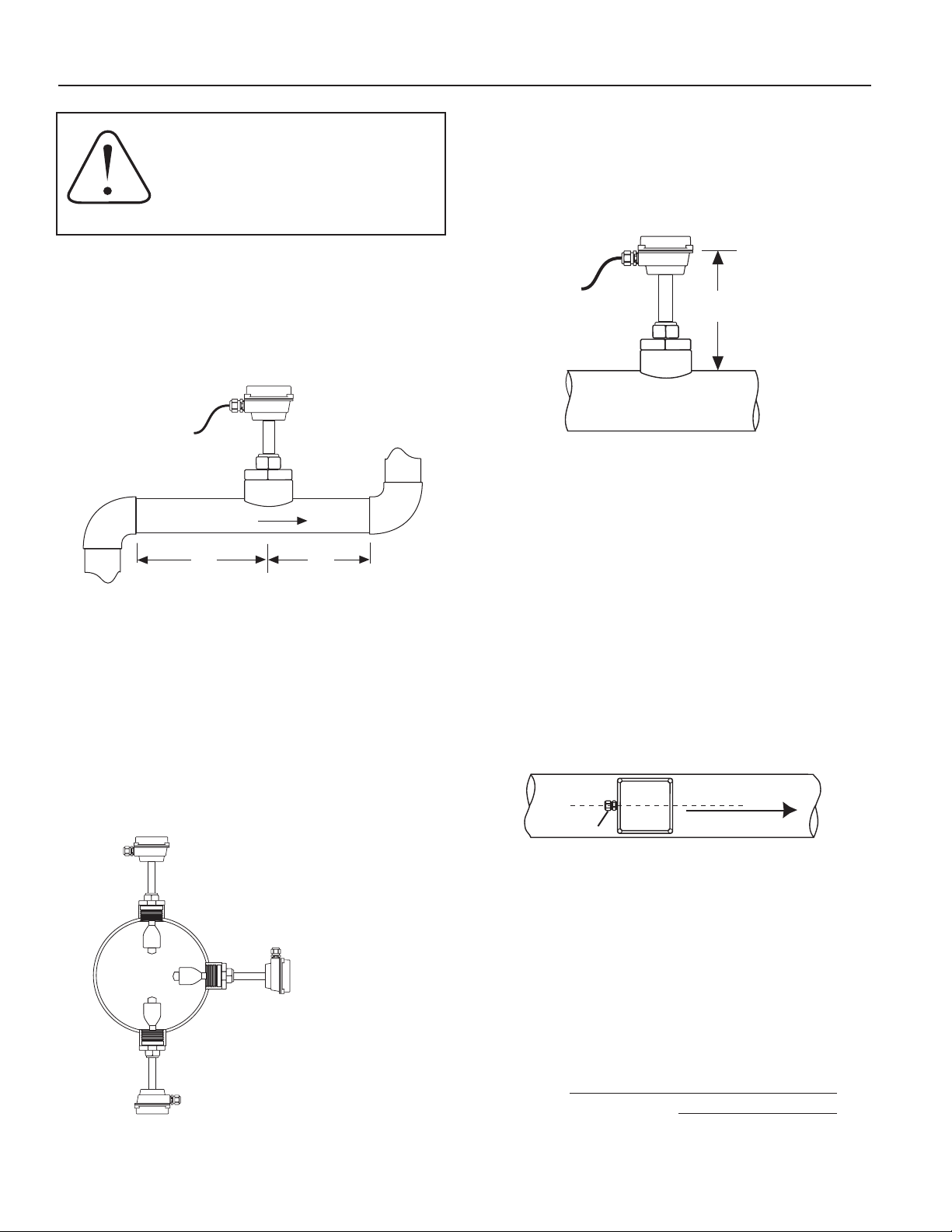
Piping. For best results, the FP6500 should be installed with
at least ten diameters of straight pipe upstream and ve down-
stream. Certain extreme situations such as partially-opened
valves are particularly difcult and may require fteen diameters
upstream (See Straight Pipe Recommendations).
FLOW
10
X Dia.
5
X Dia.
Immersion. The FP6500-Series standard sensors are not
designed for continuous underwater operation.
Depth Setting. It is important for accuracy that the sensor be
inserted to the correct depth into the pipe.
1. In Table 1, nd Dimension C for your sensor model
and pipe size.
2. Subtract wall thickness of your pipe (Table 2) to
nd Dimension D.
Horizontal is the preferred installation orientation, since it im-
proves low-ow performance slightly and avoids problems with
trapped air. Bottom, top, and vertical pipe installations are all
acceptable if required by the piping layout. See Full Pipe Recommendations.
POSITIONING THE METER
Fair (unacceptable if
air is present)
Best
3. Measuring from the outside of the pipe to the joint in
the housing, as shown in the diagram, adjust the sensor
to Dimension D and hand tighten compression nut.
4. Align the conduit housing with the centerline of the pipe,
as shown below. Be sure the arrow on the housing
points in the direction of ow.
strain relief
FLOW
5. Check Dimension D one more time.
6. Tighten the compression nut fully.
RECORD YOUR SETTINGS
Once you have the meter set up and operational, it is important to record your meter setttings and save them for
future reference.
Fair (unacceptable if uid
contains sediment)
K-Factor
Insertion Depth (Dim. D)
Page 2
Page 6
INSTALLATION
FP6501/6502 INSTALLATION
(Add -SS for stainless)
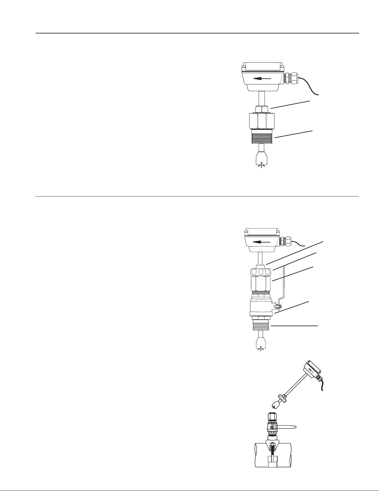
Fitting Installation. FP6501/6502 sensors come with a 1-1/2” male
NPT pipe thread adapter tting. Any tting that provides the matching
NPT female thread may be used. Installation procedure compensates
for tting height differences. Cut a minimum 1-3/4” hole in the pipe. If
possible, measure the wall thickness and write it down for use in depth
setting. Then install the threaded tting (saddle, weldolet, etc.) on the
pipe.
Meter Installation. Loosen the compression nut so that the adapter
slides freely. Pull the meter fully upward and nger-tighten the compression nut. Using a thread sealant, install the adapter in the pipe tting. Do
not overtighten. Now loosen the compression nut, lower the meter to the
appropriate depth setting (see diagram and instructions, preceding page).
Caution: Do not allow the meter to fall into the pipe uncontrolled, as
this may damag the meter. Be sure ow is in the direction of the arrow
on the housing. Tighten compression nut fully.
FP6511/6512 INSTALLATION
(Add -SS for stainless)
‘Hot tap’ FP6500 Series meters are designed to be installed and serviced
without depressurizing the pipe.
FP6501/6502
Compression nut
Adapter tting
with
standard NPT
threads
FP6511/6512
Compression nut
Fitting Installation. The sensors have a 2” NPT thread for compatibility
with the 2” isolation valve. Any tting that provides matching NPT
female thread may be used. The installation procedure compensates
for differences in tting height.
If initial installation is performed on an unpressurized pipe, cut a
minimum 1-3/4” hole in the pipe. If possible, measure the wall thickness
and write it down for use in depth setting. Then install the threaded tting
(saddle, weldolet, etc.) on the pipe.
If it is necessary to do the initial installation under pressure, any standard
hot tap drilling machine with 2” NPT adapter, such as a Transmate or a
Mueller, can be used. Ordinarily, it is not necessary to use an installation
tool, since the small-diameter tube can be controlled by hand at all but
the highest pressures.
Meter Installation. Remove the sensor unit from the valve assembly.
Using a thread sealant, install the valve assembly on the pipe tting. If
the initial installation is a pressure (“hot”) tap, remove the 1-1/2” x 2”
adapter bushing at the back of the valve. Thread the tapping machine on,
open the valve, and tap using a minimum of 1-3/4” or maximum 1-7/8”
cutter. After retracting the machine and closing the valve, reinstall the
ow sensor. When the sensor is secure, open the valve and adjust depth
setting (see diagram and instructions, preceding page). Be sure ow is
in the direction of the arrow on the housing. Tighten locking collar and
compression nut fully.
Page 3
Locking collar
2” adapter removes
to mount hot-tap
machine
Full-port 2” ball
valve allows sensor
removal
Standard 2”
NPT threads
FP6511/6512
Sensor Removal
Page 7

INSTALLATION
Table 1: Dimension "C"
3" 4" 6" 8" 10" 12" 16" 24" 30" 36"
FP6501
FP6502
FP6511
FP6512
9.20 9.03 8.69 8.35 8.01 7.67 6.99 - - -
14.20 14.03 13.69 13.35 13.01 12.67 11.99 10.63 9.61 9.59
16.21 16.01 15.71 15.31 15.01 14.7 14.01 - - -
- 20.06 19.66 19.36 19.06 18.66 17.96 16.66 15.66 14.56
Table 2: Pipe Wall Thickness
Nominal Pipe Size
3" 4" 6" 8" 10" 12" 16" 24" 30" 36"
PVC/Steel
Sch. 40
0.216 0.237 0.280 0.322 0.365 0.406 0.500 0.687 - -
Nominal Pipe Size
PVC/Steel
Sch. 80
Stainless
Steel (10S)
Stainless
Steel (40S)
Copper Tubing
(Type L)
Copper Tubing
(Type K)
Brass Pipe
Duct. Iron
(Class 52)
0.300 0.337 0.432 0.500 0.593 0.687 0.843 1.218 - -
0.120 0.120 0.134 0.148 0.165 0.180 - - - -
0.216 0.237 0.280 0.322 0.365 0.375 0.375 0.375 0.375 -
0.090 0.100 0.140 0.200 0.250 0.280 - - - -
0.109 0.134 0.192 0.271 0.338 0.405 - - - -
0.219 0.250 0.250 0.313 0.365 0.375 - - - -
0.280 0.290 0.310 0.330 0.350 0.370 0.400 0.440 0.470 0.530
Page 4
Page 8

INSTALLATION
Feet / sec.
5
Table 3: Flow (GPM) (Sched. 40 pipe)
Nominal pipe size
3" 4" 6" 8" 10" 12" 16" 24" 30" 36"
(0.3)
(0.5)
(1.0)
(2.0)
(5.0)
(10.0)
(20.0)
(30.0)
3.1 4.5 27 46.8 73.7 105 165 376 660 874
11.5 19.8 45 78 123 174 275 627 1100 1460
23 39.7 90 156 246 349 551 1250 2200 2910
46.1 79.4 180 312 492 698 1100 2510 4401 5830
115 198 450 780 1230 1740 2750 6270 11002 14570
230 397 900 1560 2460 3490 5510 12530 22005 29140
461 794 1800 3120 4920 6980 11020 25060 44010 58270
691 1190 2700 4680 7370 10470 16520 37600 66015 87410
Table 4: FP6500 Series K-factors
Nominal pipe size
3" 4" 6" 8" 10" 12" 16" 24" 30" 36"
Page 5
PVC/Steel
Sch. 40
PVC/Steel
Sch. 80
Stainless Steel
(10S)
Stainless Steel
(40S)
Copper Tubing
(Type K)
Copper Tubing
(Type L)
Brass Pipe
Duct. Iron
(Class 52)
34.246 19.221 7.830 4.611 2.883 1.859 1.224 .577 - -
38.329 21.844 8.779 4.980 3.213 2.097 1.304 .656 - -
30.331 16.581 7.045 4.270 2.621 1.703 1.160 .519 .332 -
34.246 19.221 7.830 4.611 2.883 1.836 - - - -
38.145 21.420 8.846 5.027 3.302 2.126 - - - -
37.167 20.774 8.505 4.873 3.167 2.011 - - - -
34.381 19.545 7.658 4.593 2.883 1.836 - - - -
28.137 16.994 7.238 4.213 2.633 1.681 1.065 .461 .297 .207
Page 9
INSTALLATION
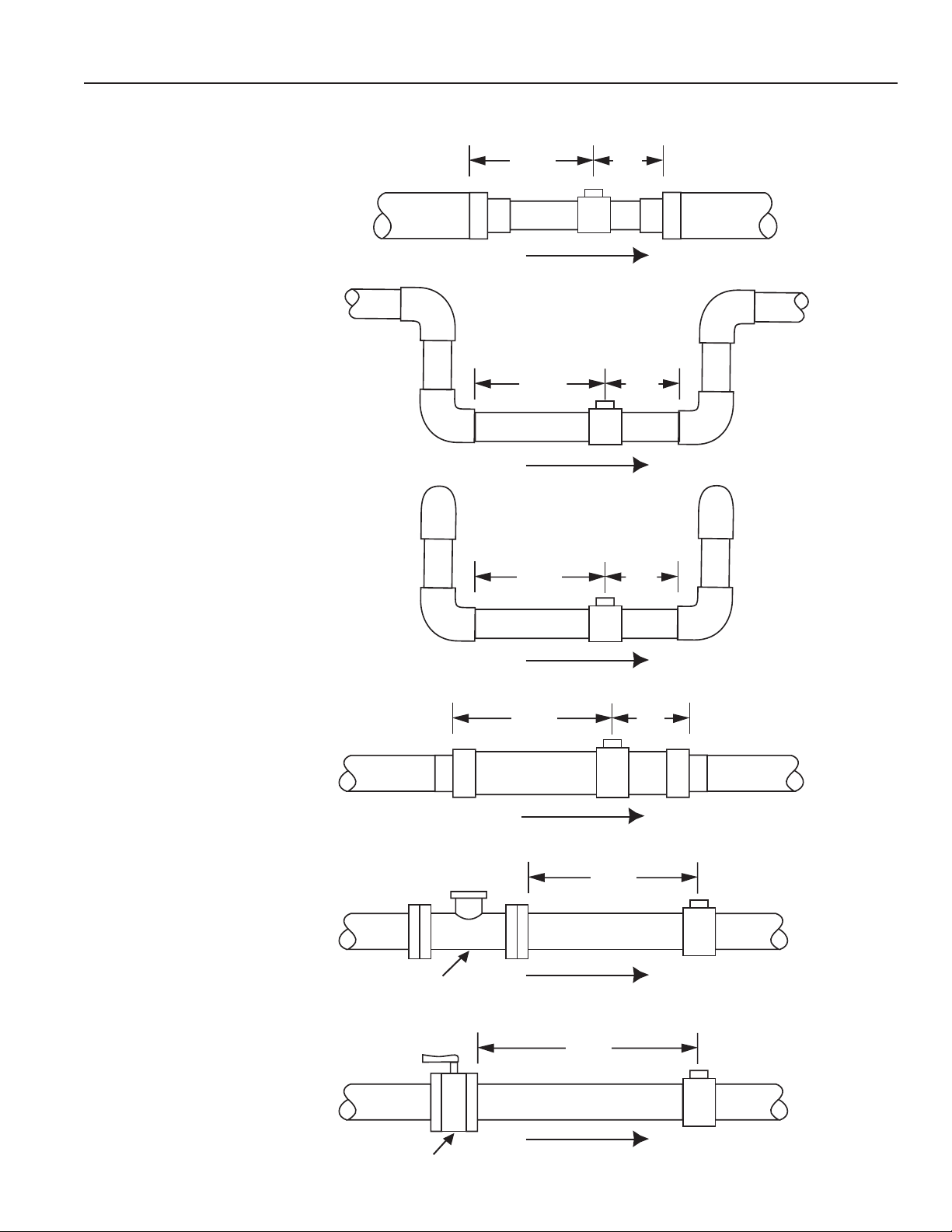
STRAIGHT PIPE RECOMMENDATIONS
(X = diameter)
Reduced Pipe
Two Elbows In Plane
Two Elbows, Out Of Plane
10X
20X
5X
5X10X
5X
Expanded Pipe
Spiral Flow
Swirling Flow
Propeller Meter
Partially Open
Buttery Valve
20X
5X
30X
50X
Page 6
Page 10

INSTALLATION
FULL PIPE RECOMMENDATIONS
Allows air pockets to form at sensor
RECOMMENDEDNOT RECOMMENDED
Ensures full pipe
RECOMMENDEDNOT RECOMMENDED
Post-valve cavitation can create air pocket Keeps pipe full at sensor
RECOMMENDEDNOT RECOMMENDED
Air can be trapped
Allows air to bleed off
Caution: These ow sensors are not recommended for installation down-
stream of the boiler feedwater pump where installation fault may expose the
ow sensor to boiler pressure and temperature. Maximum recommended
temperature is 200°F.
Page 7
Page 11
CONNECTION, OPERATION & REPAIR
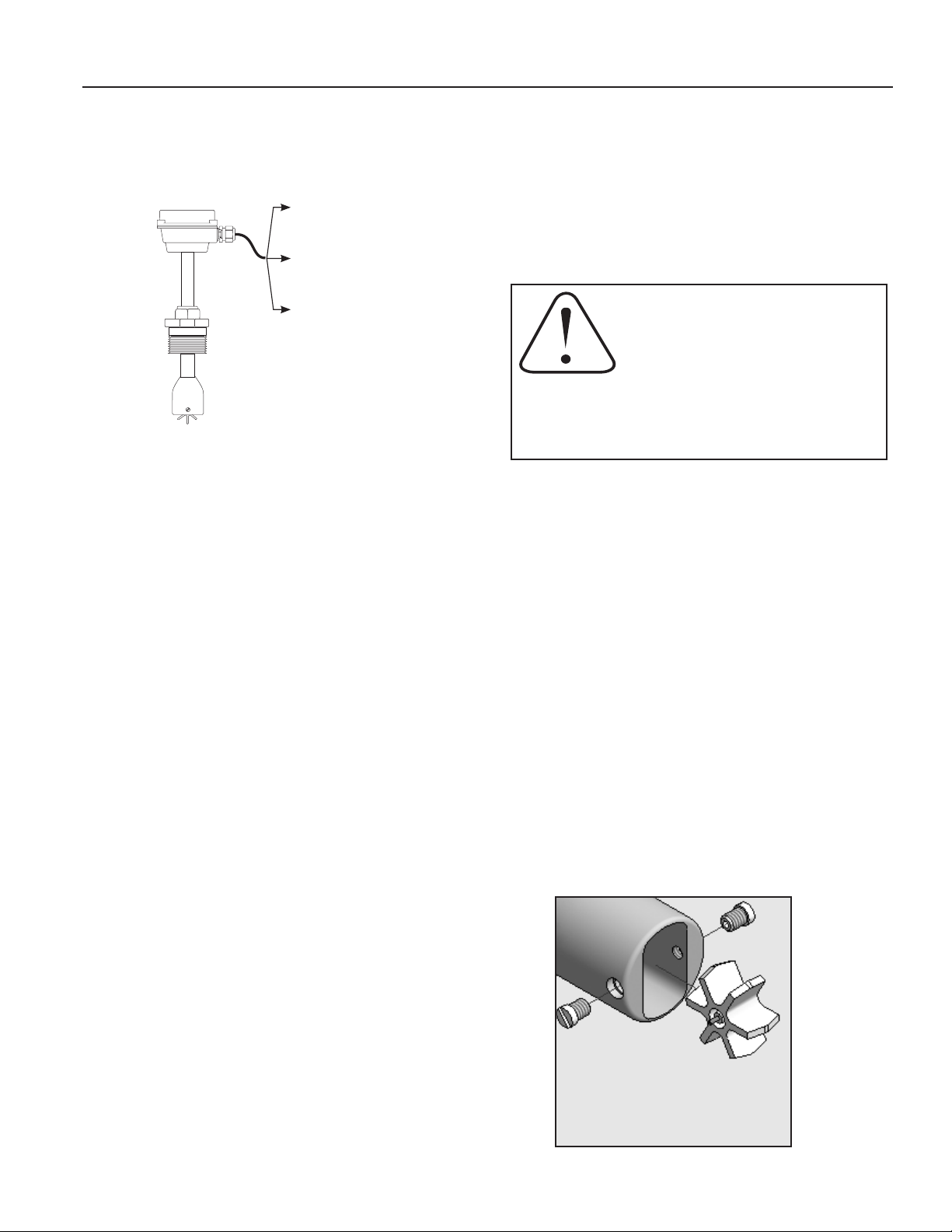
RED (+) 6-24 Vdc
WHITE (signal)
BLACK (-) Power
18' cable standard
CONNECTION
Sensors are supplied with 18 ft. of cable. See diagram for color
coding of connections.
Calibration (“K-Factor”). In order to properly process pulses
from the ow sensor, a number must be entered into the control to which the sensor is connected. This number, called the
K-factor, is the number of pulses the sensor puts out per unit
of uid passing through the pipe. It is provided in pulses per
gallon, and is given on the chart “K-factors for Various Pipe
Sizes.” These numbers are based on extensive testing, which
has shown close agreement between different FP6500-Series
sensors in the same installation. Typically, most K-factor error
can be attributed to installation variables, such as depth setting
and tting conguration.
It is occasionally possible to eld calibrate a sensor by catching
the uid in a measured container and comparing with the number
of pulses recorded. (To record individual pulses, set the K-factor
on the control to 1.00.) This is especially desirable if the installation has less than the recommended length of straight pipe
upstream of the sensor.
OPERATION
Theory. In principle, an insertion ow sensor measures the veloc-
ity of ow at one point in the pipe, and ow rate and total can be
inferred from this one point. Accuracy is decreased by any factor
which makes the ow at the measured point unrepresentative
of the entire ow stream. This includes distorted ow patterns
caused by upstream ttings too close to the sensor. The worst offenders are ttings that increase the ow on one side of the pipe,
such as partially-opened gate or buttery valves. Fluid moving in
a pipe does not all ow at the same velocity. Toward the center
of the pipe, uid moves faster than at the wall, and the relationship between the two changes as overall ow rate increases.
This change in the “velocity prole” can result in non-linearity,
which means that the K-factor that is correct for one ow rate
may be incorrect for another. The recommended depth settings
have been carefully chosen to minimize this source of error, and
should be followed carefully, especially in the smaller pipe sizes.
Flow Range. These sensors are designed to operate at
ow velocities of 0.3 to 30 feet per second. (See chart for
conversion to gallons per minute.) If erratic readings are
encountered at low ows, check the chart to see if ow is
below minimum for the pipe size. The standard shaft and
bearings should have a long life at continuous high ow.
REPAIR
CAUTION! Never attempt to remove a
ow sensor when there is pressure in
the pipe. Loosen the compression nut
slowly to release any trapped pressure.
If uid sprays out when removing the
sensor, stop turning and depressurize the pipe. Failure
to do so could result in the sensor being thrown from
the pipe, resulting in damage or serious injury.
Rotor Replacement. Rotors are easily eld-replaced. Shaft
and rotor are a single unit, and are not replaced separately.
If replacement is due only to normal shaft wear, bearing replacement is probably not necessary. If the rotor has been
damaged by impact, the bearings should also be replaced.
Rotor and bearings can be ordered as a kit, FP15827. Follow these steps:
1. Unscrew the threaded bearing housings to expose
the shaft ends. If bearings are being replaced, back
them completely out.
2. Remove the rotor. Put the new rotor in its place.
3. Thread in one bearing housing part way, then the
other. Take care to start the end of the shaft into
the bearing hole before tightening further.
4. Screw in bearing housings until they bottom.
Note: Do not use excessive force.
5. Check for free spin. Blowing lightly on the rotor
should result in it spinning rapidly and coasting to
a smooth stop.
Page 8
Page 12
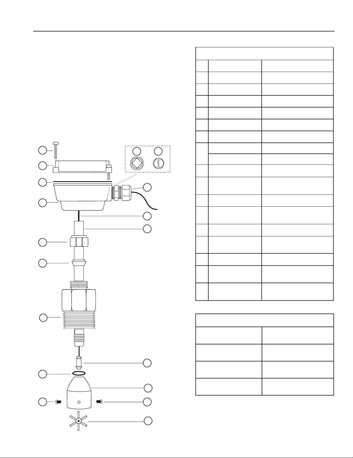
2
1
9
8
15
1
6
12
5
6
4
3
7
14
13
11
10
15
8
REPAIR & PARTS
Signal
The ow sensor has only one moving part, the rotor. If this is
turning properly and there is no signal, the Hall-effect sensor is
not operating properly. To check the signal, apply 12 Vdc regulated* power to the red (+) and black (-) leads. Set a multimeter
to voltage reading. Put the positive multimeter lead on the red
wire and the negative lead on the white wire. Slowly turn the
rotor. Voltage reading should swing between +12 Volts and 0
Volts as the rotor turns. If it does not, the Hall effect sensor
is not working properly. Checking for continuity is not a useful
test of these sensors.
*NOTE: An unregulated power supply can exceed max voltage of micro
powered sensor (gray cable) and damage sensor.
FP6501/6502 Parts
1 Upper housing assembly 30475
2 Gasket 26211
3 Lower housing Not Field Replaceable
4 Housing screw (4 req'd) 26229
5 Plug, steel 26073
6 Plug, plastic 26079
Parts Explosion
7 Strain relief 07655
Pickup, Micropower (for FT415)
8
Pickup, Standard (for FT420)
9 Tube Not Field Replaceable
10 Compression nut
11 Compression ferrule 26065
12 Adapter tting
13 Rotor housing O-ring (EPDM) 16454
14 Rotor housing
15 Jewel bearings (2 req) 25901
16 Rotor with shaft
Rotor repair kit
17
(includes of #15 & #16)
29953
26310
14199 (Brass)
15064 (S/S)
30998 (Brass)
30999 (S/S)
14220 (Brass)
15220 (S/S)
11130 (PVDF/Tungsten Carbide)
11132 (PVDF/Ceramic)
25902 (PVDF/Tungsten Carbide)
12131 (PVDF/Ceramic)
Page 9
HOT TAP: FP6511/6512 Parts (not shown)
Adapter tting
Ball valve assembly
Collar, locking
Hex nipple, 2"
14180 (Brass)
15060 (S/S)
14225 (Brass)
15225 (S/S)
14190 (Brass)
15070 (S/S)
14210 (Brass)
15100 (S/S)
Page 13

TROUBLESHOOTING
Problem
No pulse output
Output pulses incorrect
Jumpy reading
Probable Cause Try...
Below minimum ow cutoff
Empty pipe
No power
Incorrect depth setting
Pipe not full
Not enough straight pipe
Fluctuating ow rate
Fluctuating around low ow cutoff
Not enough straight pipe
Check Table for velocity vs. pipe size
Check plumbing
Check connections
Check depth setting from Dimension “C” table
Refer to Installation/diagrams
Refer to Installation/diagrams
Refer to installation diagrams
Check Table for velocity vs. pipe size
Refer to Installation/diagrams
Page 10
Page 14

WARRANTY/DISCLAIMER
FOR NON-WARRANTY REPAIRS,
OMEGA ENGINEERING, INC. warrants this unit to be free of defects in materials and workmanship for a
period of 13 months f rom date of purchase. OMEGA’s WARRANTY adds an additional one (1) month
grace period to the normal one (1) year product warranty to cover handling and shipping time. This
ensures that OMEGA’s customers receive maximum coverage on each product.
If the unit malfunctions, it must be re t u r ned to the factory for evaluation. O M E G A ’s Customer Serv i c e
D e p a rtm ent will issue an Authorized Return (AR) number immediately upon phone or written re q u e s t .
Upon examination by OMEGA, if the unit is found to be defective, it will be re p a i red or replaced at no
c h a rge. O M E G A ’s WARRANTY does not apply to defects resulting from any action of the purc h a s e r ,
including but not limited to mishandling, improper interfacing, operation outside of desi
i m p roper re p a i r, or unauthorized modification. This WARRANTY is VOID if the unit shows evidence of
having been tampered with or shows evidence of having been damaged as a result of excessive corro s i o n ;
or current, heat, moisture or vibration; improper specification; misapplication; misuse or other operating
conditions outside of OMEGA’s c o n t r ol. Components in which wear is not warranted, include but are not
limited to contact points, fuses, and triacs.
OMEGA is pleased to o ffer suggestions on the use of its various p roducts. Howev er,
OMEGA neither assumes responsibility for any omissions or e
damages that result from the use of its products in accordance with information provided by
OMEGA, either verbal or written. OMEGA warrants only that the parts manufactured by the
company will be as specified and free of defects. OMEGA MAKES NO OTHER WARRANTIES OR
R E P R E S E N T ATIONS OF ANY KIND WHATSOEVER, EXPRESSED OR IMPLIED, EXCEPT THAT OF
TITLE, AND ALL IMPLIED WARRANTIES INCLUDING ANY W
AND FITNESS FOR A PA R TICULAR PURPOSE ARE HEREBY DISCLAIMED. LIMITATION OF
L I A B I L I T Y: The remedies of purchaser set forth herein are exclusive, and the total liability of
OMEGA with respect to this ord e r , whether based on contract, warr a n t y, negligence,
indemnification, strict liability or otherwise, shall not exceed the purchase price of the
componen t upon which liab ility is based. In no eve n t shall OM EGA be liab le for
co
nsequential, incidental or special damages.
CONDITIONS: Equipment sold by OMEGA is not intended to be used, nor shall it be used: (1) as a “Basic
Component” under 10 CFR 21 (NRC), used in or with any nuclear installation or activity; or (2) in medical
applications or used on humans. Should any Product(s) be used in or with any nuclear installation or
a c t i v i t y , medical application, used on humans, or misused in any way, OMEGA assumes no re s p o n s i b i l i t y
as set forth in our basic WA R R A N T Y/ D ISCLAIMER language, and, additionally, purchaser will indemnify
OMEGA and hold OMEGA h a rmless from any liability or damage whatsoever arising out of the use of the
P roduct(s) in such a manner.
rrors nor assumes liability for any
ARRANTY OF MERCHANTA B I L I T Y
gn limits,
RETURN REQUESTS/INQUIRIES
Direct all warranty and repair requests/inquiries to the OMEGA Customer Service Department. BEFORE
RETURNING ANY PRODUCT(S) TO OMEGA, PURCHASER MUST OBTAIN AN AUTHORIZED RETURN
(AR
) NUMB E R F ROM OME G A’ S C U S TOME R S E RV I C E DEPA R TMENT ( I N O R DER TO AV O I D
PROCESSING DELAYS). The assigned AR number should then be marked on the outside of the return
package and on any correspondence.
The purchaser is responsible for shipping charges, freight, insurance and proper packaging to prevent
breakage in transit.
WARRANTY RETURNS, please have the
FOR
following information available BEFORE
contacting OMEGA:
1 . P u r chase Order number under which the pro d u c t
was PURCHASED,
2. Model and serial number of the product under
warranty, and
3. Repair instructions and/or specific problems
relative to the product.
OMEGA’s policy is to make running changes, not model changes, whenever an improvement is possible. This affords
our customers the latest in technology and engineering.
OMEGA is a registered trademark of OMEGA ENGINEERING, INC.
© Copyright 2005 OMEGA ENGINEERING, INC. All rights reserved. This document may not be copied, photocopied,
reproduced, translated, or reduced to any electronic medium or machine-readable form, in whole or in part, without the
prior written consent of OMEGA ENGINEERING, INC.
for current repair charges. Have the following
information available BEFORE contacting OMEGA:
1. Purchase Order number to cover the COST
of the repair,
2. Model and serial number of the product, and
3. Repair instructions and/or specific problems
relative to the product.
consult OMEGA
Page 15

W h e r e Do I Find Eve rything I Need for
P r ocess Measurement and Control?
OME GA…Of Cours e !
Shop online at omega.com
T E M P E R A T U R E
Thermocouple, RTD & Thermistor Probes, Connectors, Panels & Assemblies
Wire: Thermocouple, RTD & Thermistor
Calibrators & Ice Point References
Recorders, Controllers & Process Monitors
Infrared Pyrometers
PRESSURE, STRAIN AND FO R C E
Transducers & Strain Gages
Load Cells & Pressure Gages
Displacement Transducers
Instrumentation & Accessories
F L OW / L E V E L
Rotameters, Gas Mass Flowmeters & Flow Computers
Air Velocity Indicators
Turbine/Paddlewheel Systems
Totalizers & Batch Controllers
p H / C O N D U C T I V I T Y
pH Electrodes, Testers & Accessories
Benchtop/Laboratory Meters
Controllers, Calibrators, Simulators & Pumps
Industrial pH & Conductivity Equi
pment
DATA AC Q U I S I T I O N
Data Acquisition & Engineering Software
Communications-Based Acquisition Systems
Plug-in Cards for Apple, IBM & Compatibles
Datalogging Systems
Recorders, Printers & Plotters
H E A T E R S
Heating Cable
Cartridge & Strip Heaters
Immersion & Band Heaters
Flexible Heaters
Laboratory Heaters
E N V I R O N M E N T A L
M O N I T ORING AND CONTRO L
Metering & Control Instrumentation
R e f r a c t o m e t e r s
Pumps & Tubing
Air, Soil & Water Monitors
Industrial Water & Wastewater Treatment
pH, Conductivity & Dissolved Oxygen Instruments
PL-OM-10611-051811
05/18/2011
M-1949/0511
 Loading...