

Page 1
User’s Guide
Shop online at
omega.com
e-mail: [email protected]
For latest product manuals:
www.omegamanual.info
SM
FP-5200
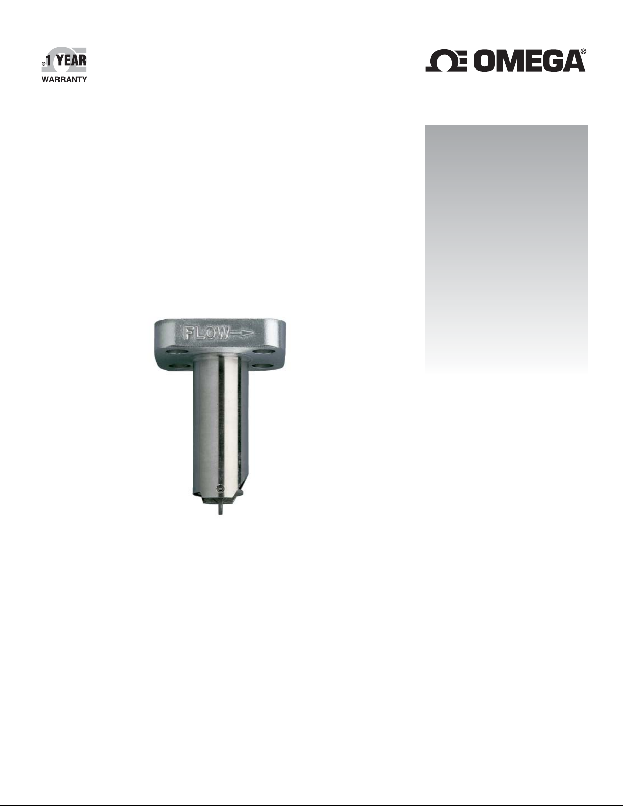
Flow Sensor
Page 2

omega.com [email protected]
Servicing North America:
U.S.A. Omega Engineering, Inc.
Headquarters: Toll-Free: 1-800-826-6342 (USA & Canada only)
Customer Service: 1-800-622-2378 (USA & Canada only)
Engineering Service: 1-800-872-9436 (USA & Canada only)
Tel: (203) 359-1660 Fax: (203) 359-7700
e-mail: [email protected]
For Other Locations Visit omega.com/worldwide
The information contained in this document is believed to be correct, but OMEGA accepts no liability for any errors it contains, and reserves
the right to alter specifications without notice.
Page 3
OMEGA FP-5200 Flow Sensor Instructions
uded
SAFETY INSTRUCTIONS
1. Do not remove from pressurized lines.
2. Do not exceed maximum temperature/pressure specifi cations.
3. Pipe fi tting must be installed by certifi ed welder only.
4. Do not install/service without following installation instructions
(see sensor manual).
5. Wear safety goggles and face shield during installation/service.
6. Do not alter product construction.
7. Failure to follow safety instructions could result in severe
personal injury!
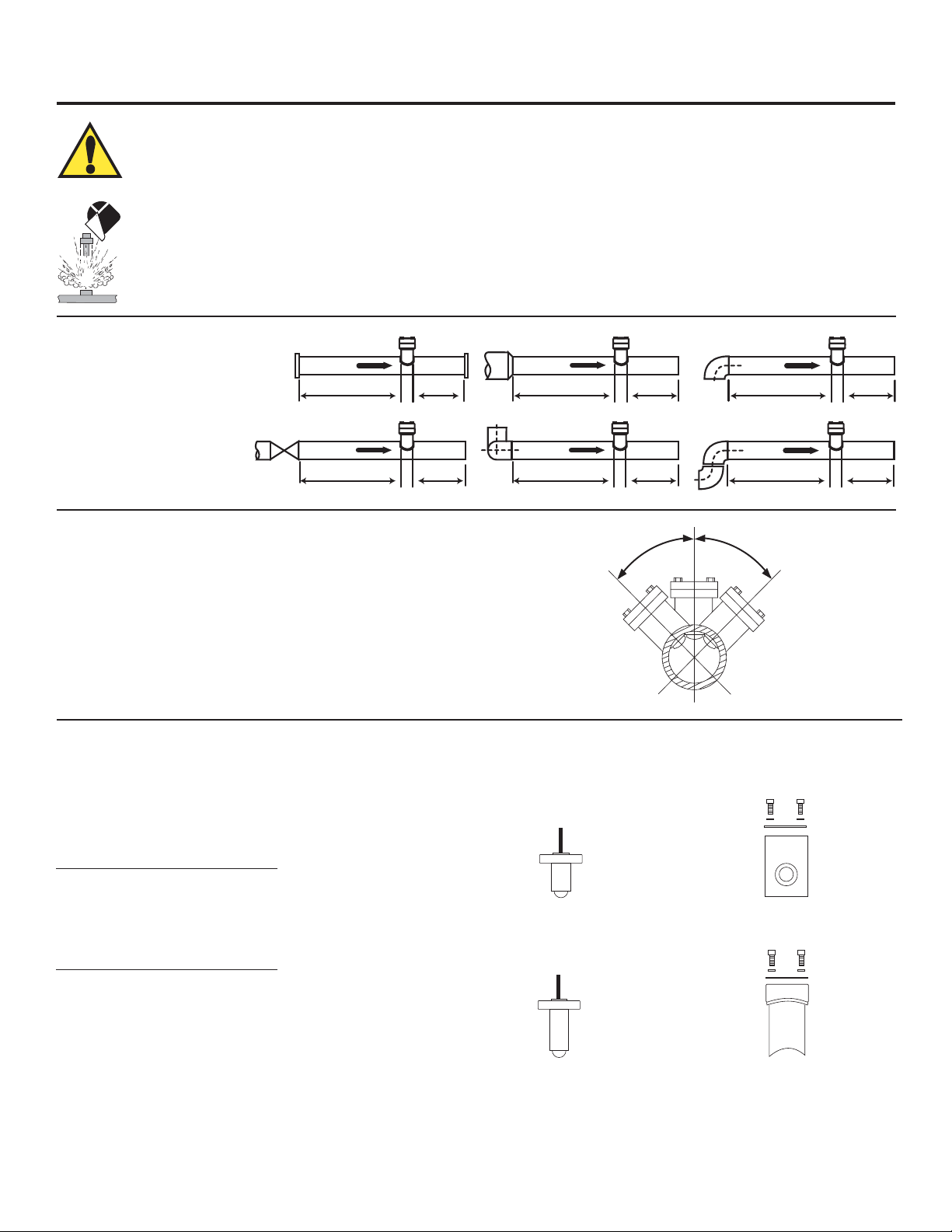
1. Location of Fitting
Recommended sensor
upstream/downstream mounting
requirements.
Flange
Valve/Gate
Inlet Outlet
10 X I.D. 5 X I.D.
50 X I.D. 5 X I.D.
Reducer
15 X I.D. 5 X I.D.
2 x 90° Elbow
40 X I.D. 5 X I.D.
2. Sensor Mounting Position
• Horizontal pipe runs: Mount sensor in the upright (0°) position for best overall
performance. Mount at a maximum of 45° when air bubbles are present. Do
not mount on the bottom of pipe when sediments are present.
Maximum Operating Pressure/Temperature:
FP-5200 Series Sensor with:
• FP-5200 Series Tee & Mini-Tap Fittings:
103 bar (1500 psi) @ 149 °C (300 °F)
90° Elbow
20 X I.D. 5 X I.D.
2 x 90° Elbow
25 X I.D. 5 X I.D.
45°
45°
• Vertical pipe runs: Sensor must be mounted in lines with UPWARD fl ow only.
3. Sensor/Fitting Selection
The FP-5200 Sensor is designed for installation into SCH 40
stainless steel pipes via FP-5200 Series Tee, Mini-Tap or Saddle
fi ttings, see options below:
FP-5200 Series Tee Fittings
Pipe (in.) Sensor Fitting
0.50 FP-5200 FP-5205
0.75 FP-5200 FP-5207
1.00 FP-5200 FP-5210
FP-5200 Series Mini-Tap Fittings
Pipe (in.) Sensor Fitting
1.25 FP-5201 FP-5212
1.50 FP-5201 FP-5215
2.00 FP-5201 FP-5220
2.50 FP-5201 FP-5225
3.00 FP-5201 FP-5230
4.00 FP-5201 FP-5240
5.00 FP-5201 FP-5250
6.00 FP-5201 FP-5260
8.00 FP-5201 FP-5280
10.0 FP-5201 FP-5281
12.0 FP-5201 FP-5282
Sensor
Sensor
Wetted fitting materials:
316 SS
hardware incl
Wetted fitting materials:
316 SS & 347 SS
Mini-Tap Fitting,
hardware included
Tee Fitting,
1OMEGA FP-5200 Flow Sensor Instructions
Page 4
4. Fitting Installation, Required Hardware
Tee & Mini-Tap Fittings
• 0.5 to 1 inch pipes, FP-5200 Series fi tting required
• 1.25 to 12 inch pipes: FP-5200 Series fi tting and 27 mm (1-1/16 in.) diameter drill required
• Mini-Tap fi ttings are welded onto the pipe and are used with FP-5200 sensors.
4.1 Installation, Tee & Mini-Tap Fittings
1. Select an appropriate mounting location as outlined in sections 1 and 2.
2. Depressurize and drain pipe.
3. Use the following welding and installation procedures appropriate for your fi tting/pipe size:
FP-5200 Series Tee Fittings, 0.5 to 1 inch:
• Insert pipe into fi tting socket
• Make sure the pipe is parallel to the bottom of the Mini-Tap fi tting.
• Weld pipe into place.
FP-5200 Series Mini-Tap Fittings, 1.25 to 12 inch:
• Drill a 27 mm (1-1/16 in.) diameter hole completely through the ONE surface of the pipe. Thoroughly deburr inner and outer edges
of hole.
• Tack weld the Mini-Tap fi tting onto the pipe, making sure the hole in the pipe is lined up with the Mini-Tap fi tting hole.
• Weld the Mini-Tap fi tting onto the pipe.
FP-5200 Series Saddle Fitting
• 27 mm (1-1/16 in.) diameter drill required.
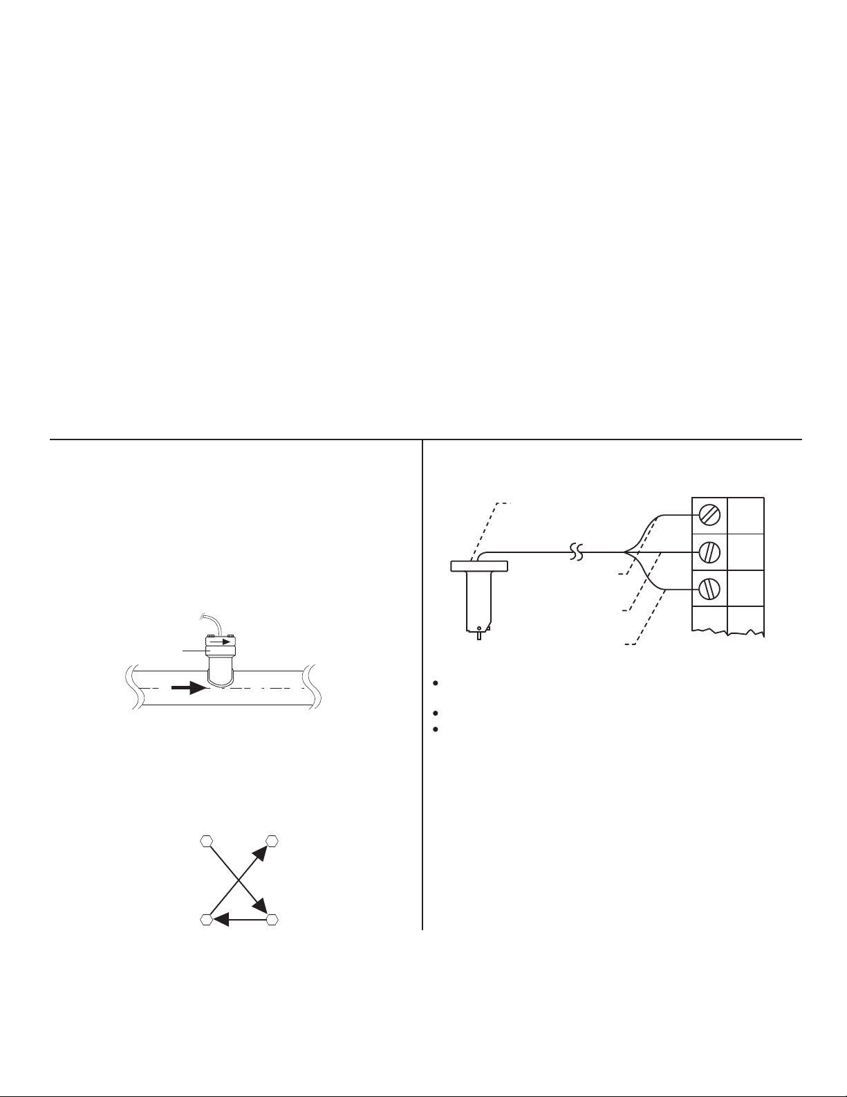
5. Sensor Installation
1. Set the gasket supplied with the fi tting onto the fi tting fl ange,
making sure the holes align.
2. Remove the red rotor protection cap and insert the sensor into
the fi tting, making sure not to bump the rotor assembly. Make
sure the arrow on the side of the sensor is pointing in the
direction of fl ow.
Fitting
flange
Flow
3. Slip two washers onto each bolt and insert the bolt/washer
onto each of the four fi tting fl ange holes.
4. Snug all four fl ange bolts in a criss-cross pattern. Using a
torque wrench (when possible), torque the fl ange nuts in a
criss-cross pattern to 52 foot-pounds.
Flow sensor
arrow
14
Flange
bolt torque
pattern
6. Sensor Wiring
1/2 in. NPT
conduit port
(AC signal out)
(AC signal out)
FP-5200 Series
Use 2-conductor shielded cable for cable splices up to
60 m (200 ft).
Maintain cable shield through splice.
Shield the unjacketed silver (ground) wire using electrical tape
to prevent potential noise interference and/or shorting hazards.
black
red
silver
(ground)
Blk
F-
Red
F+
Shld.
Instruments
23
2 OMEGA FP-5200 Flow Sensor Instructions
Page 5
7. Sensor Removal Procedure
1. Depressurize and drain pipe.
2. Remove the four sensor fl ange bolts and lockwashers.
Pull upward on the sensor fl ange with an alternating twisting
motion.
WARNING!
Never remove a sensor from a pressurized
pipeline. Always wear protective clothing
during sensor installation/service.
8. Maintenance
The FP-5200 Series Sensor requires little or no maintenance of any kind, with the exception of occasionally cleaning the
sensor/paddlewheel.
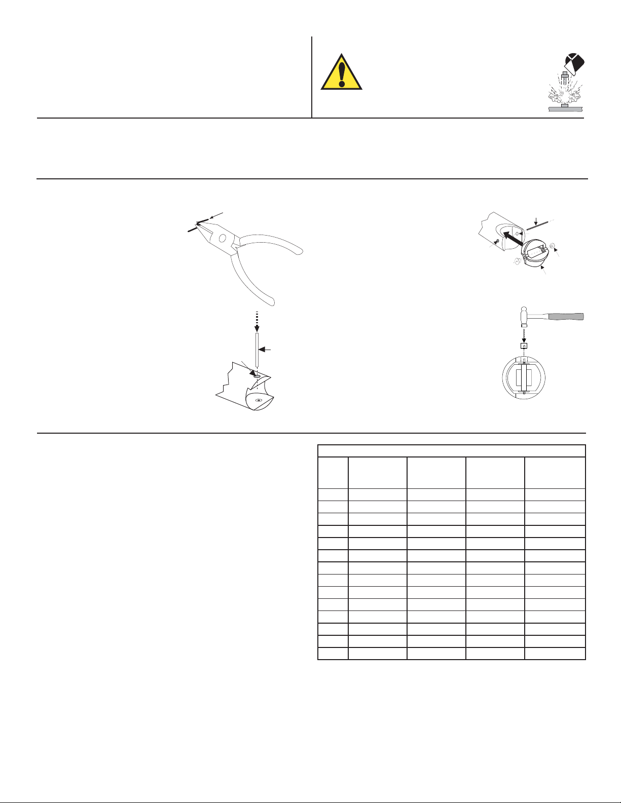
9. Rotor Replacement Procedure
1. With a small pair of needle-nose
Rotor Pin
pliers, fi rmly grip the center of
the rotor pin (axle) and with a
twisting motion, bend the rotor
pin into an "S" shape. This
should pull the ends of the pin
out of the retainers and free the
rotor assembly.
2. Remove retainer from each side
by gently tapping it inwards using
a punch. Install a new retainer
with its rotor pin clearance hole
inward. Only install one retainer
Retainer
Punch
at this time.
10. K-Factors
The K-Factor is the number of pulses the sensor will generate for
each engineering unit of fl uid which passes. They are listed in U.S.
gallons and in liters. For example, in a 1 inch SCH 40S stainless
steel pipe, the sensor generates 266.17 pulses per gallon of fl uid
passing the rotor. K-Factors are listed for SCH 40S stainless steel
pipes up to 12 inch.
3. Insert the new rotor assembly
Rotor Pin
and bearings into the rotor
housing of the sensor and
place the new rotor pin (axle)
through the open end of the
rotor housing, through the
rotor and bearings, and into the
previously installed retainer.
Existing
Retainer
Rotor
Assembly
4. Tap the second retainer (rotor pin
clearance hole inwards) into the
hole while lining up the rotor pin
with the center of the retainer hole.
This completes the rotor replacement
procedure.
SCH 40S STAINLESS STEEL PIPE PER ANSI B36.19
PIPE
SIZE
(in.)
1/2 873.03 230.66 0.0687 0.2601
3/4 515.41 136.17 0.1164 0.4406
1 266.17 70.322 0.2254 0.8532
1-1/4 148.84 39.324 0.4031 1.5258
1-1/2 107.98 28.528 0.5557 2.1032
2 64.808 17.122 0.9258 3.5042
2-1/2 44.685 11.806 1.3427 5.0822
3 28.579 7.5506 2.0994 7.9464
4 16.302 4.3070 3.6805 13.931
5 10.237 2.7046 5.8611 22.184
6 7.0057 1.8509 8.5645 32.416
8 3.9641 1.0473 15.136 57.289
10 2.4690 0.6523 24.301 91.981
12 1.6894 0.4463 35.516 134.43
K-FACTOR
PULSES/
U.S. GAL
K-FACTOR
PULSES/
U.S. LITER
A-FACTOR
GPM/Hz
A-FACTOR
LPM/Hz
New
Bearings
Conversion Formulas
1 U.S. gallon = 0.003785 cubic meters
0.000003069 Acre feet
8.3454 pounds of water
3OMEGA FP-5200 Flow Sensor Instructions
Page 6
11. Specifi cations
r
General Data
Flow velocity range: 0.5 to 6 m/s (1.6 to 20 ft/s)
Frequency output: 29 to 46 Hz per m/s (9 to 14 Hz per ft/s)
Linearity: ±1% of full range
Repeatability: ±0.5% of full range
Pipe size range: 13 to 305 mm (0.5 to 12 in.)
Cable length: 7.6 m (25 ft), can splice up to 60 m
(200 ft.) with no signifi cant degradation of
signal strength
Cable type: 150 °C 22 AWG, 2-conductor w/shield
Materials
Sensor body: ACI type CF-8M (316 cast stainless steel)
per ASTM A351
Rotor material: CD4MCu stainless steel
Rotor pin: Tungsten Carbide (316 stainless steel,
optional)
Retainers (2): 316 stainless steel
Rotor bearings (2): Fluoroloy B
®
Electrical Data
Voltage output: Approximate sine wave,
0.005 to 0.008 Vpp per Hz
Coil resistance: 11.6 kΩ @ 25 °C
Coil inductance: 3.5 H @ 25 °C
Quality Standards
• CE
• Manufactured under ISO 9001
Ambient Conditions
Maximum Pressure/Temperature Limitations:
• FP-5200 Series Sensor
with FP-5200 Series Tee
or Mini-Tap Fitting: 103 bar (1500 psi) max.
@ 149 °C (300 °F)
12. Accessories
retainer retaine
rotor pin
Refer to section 3 for a list of available sensors and fi ttings.
Part no. Description
FP-52648 Fitting cap kit, cap and gasket
bearing
bearing
FP-52509 Rotor kit, 316 SS pin
FP-52509-2 Rotor kit, Tungsten pin
M2489 Instruction manual
FP-52509/FP-52509-2 Rotor kit
rotor
Chemical Compatibility Warning
The retaining nuts of paddlewheel sensors, pH and ORP sensors as well as Magmeters are not designed for prolonged
contact with aggressive substances. Strong acids, caustic substances and solvents or their vapor may lead to failure of the
retaining nut, ejection of the sensor and loss of the process fl uid with possibly serious consequences, such as damage to
equipment and serious personal injury. Retaining nuts that may have been in contact with such substances e.g. due to leakage or spilling, must be replaced.
4 OMEGA FP-5200 Flow Sensor Instructions
Page 7

WARRANTY/DISCLAIMER
OMEGA ENGINEERING, INC. warrants this unit to be free of defects in materials and workmanship for a
period of 13 months from date of purchase. OMEGA’s WARRANTY adds an additional one (1) month
grace period to the normal one (1) year product warranty to cover handling and shipping time. This
ensures that OMEGA’s customers receive maximum coverage on each product.
If the unit malfunctions, it must be returned to the factory for evaluation. OMEGA’s Customer Service
Department will issue an Authorized Return (AR) number immediately upon phone or written request.
Upon examination by OMEGA, if the unit is found to be defective, it will be repaired or replaced at no
charge. OMEGA’s WARRANTY does not apply to defects resulting from any action of the purchaser,
including but not limited to mishandling, improper interfacing, operation outside of design limits,
improper repair, or unauthorized modification. This WARRANTY is VOID if the unit shows evidence of
having been tampered with or shows evidence of having been damaged as a result of excessive corrosion;
or current, heat, moisture or vibration; improper specification; misapplication; misuse or other operating
conditions outside of OMEGA’s control. Components in which wear is not warranted, include but are not
limited to contact points, fuses, and triacs.
OMEGA is pleased to offer suggestions on the use of its various products. However,
OMEGA neither assumes responsibility for any omissions or errors nor assumes liability for
any damages that result from the use of its products in accordance with information provided
by OMEGA, either verbal or written. OMEGA warrants only that the parts manufactured by the
company will be as specified and free of defects. OMEGA MAKES NO OTHER WARRANTIES OR
REPRESENTATIONS OF ANY KIND WHATSOEVER, EXPRESSED OR IMPLIED, EXCEPT THAT OF
TITLE, AND ALL IMPLIED WARRANTIES INCLUDING ANY WARRANTY OF MERCHANTABILITY
AND FITNESS FOR A PARTICULAR PURPOSE ARE HEREBY DISCLAIMED. LIMITATION OF
LIABILITY: The remedies of purchaser set forth herein are exclusive, and the total liability of
OMEGA with respect to this order, whether based on contract, warranty, negligence,
indemnification, strict liability or otherwise, shall not exceed the purchase price of the
component upon which liability is based. In no event shall OMEGA be liable for
consequential, incidental or special damages.
CONDITIONS: Equipment sold by OMEGA is not intended to be used, nor shall it be used: (1) as a “Basic
Component” under 10 CFR 21 (NRC), used in or with any nuclear installation or activity; or (2) in medical
applications or used on humans. Should any Product(s) be used in or with any nuclear installation or
activity, medical application, used on humans, or misused in any way, OMEGA assumes no responsibility
as set forth in our basic WARRANTY/D ISCLAIMER language, and, additionally, purchaser will indemnify
OMEGA and hold OMEGA harmless from any liability or damage whatsoever arising out of the use of the
Product(s) in such a manner.
RETURN REQUESTS/INQUIRIES
Direct all warranty and repair requests/inquiries to the OMEGA Customer Service Department.
BEFORE RETURNING ANY PRODUCT(S) TO OMEGA, PURCHASER MUST OBTAIN AN AUTHORIZED
RETURN (AR) NUMBER FROM OMEGA’S CUSTOMER SERVICE DEPARTMENT (IN ORDER TO AVOID
PROCESSING DELAYS). The assigned AR number should then be marked on the outside of the return
package and on any correspondence.
The purchaser is responsible for shipping charges, freight, insurance and proper packaging to prevent
breakage in transit.
FOR WARRANTY RETURNS, please have the
following information available BEFORE contacting
OMEGA:
1. Purchase Order number under which the product
was PURCHASED,
2. Model and serial number of the product under
warranty, and
3. Repair instructions and/or specific problems
relative to the product.
OMEGA’s policy is to make running changes, not model changes, whenever an improvement is possible. This affords
our customers the latest in technology and engineering.
OMEGA is a registered trademark of OMEGA ENGINEERING, INC.
© Copyright 2016 OMEGA ENGINEERING, INC. All rights reserved. This document may not be copied, photocopied,
reproduced, translated, or reduced to any electronic medium or machine-readable form, in whole or in part, without the
prior written consent of OMEGA ENGINEERING, INC.
FOR NON-WARRANTY REPAIRS,
OMEGA for current repair charges. Have
the following information available BEFORE
contacting OMEGA:
1. Purchase Order number to cover the COST
of the repair,
2. Model and serial number of the product, and
3. Repair instructions and/or specific problems
relative to the product.
consult
Page 8

Where Do I Find Everything I Need for
Process Measurement and Control?
OMEGA…Of Course!
Shop online at omega.com
TEMPERATURE
Thermocouple, RTD & Thermistor Probes, Connectors, Panels & Assemblies
Wire: Thermocouple, RTD & Thermistor
Calibrators & Ice Point References
Recorders, Controllers & Process Monitors
Infrared Pyrometers
PRESSURE, STRAIN AND FORCE
Transducers & Strain Gages
Load Cells & Pressure Gages
Displacement Transducers
Instrumentation & Accessories
FLOW/LEVEL
Rotameters, Gas Mass Flowmeters & Flow Computers
Air Velocity Indicators
Turbine/Paddlewheel Systems
Totalizers & Batch Controllers
SM
pH/CONDUCTIVITY
pH Electrodes, Testers & Accessories
Benchtop/Laboratory Meters
Controllers, Calibrators, Simulators & Pumps
Industrial pH & Conductivity Equipment
DATA ACQUISITION
Communications-Based Acquisition Systems
Data Logging Systems
Wireless Sensors, Transmitters, & Receivers
Signal Conditioners
Data Acquisition Software
HEATERS
Heating Cable
Cartridge & Strip Heaters
Immersion & Band Heaters
Flexible Heaters
Laboratory Heaters
ENVIRONMENTAL
MONITORING AND CONTROL
Metering & Control Instrumentation
Refractometers
Pumps & Tubing
Air, Soil & Water Monitors
Industrial Water & Wastewater Treatment
pH, Conductivity & Dissolved Oxygen Instruments
M-2489/0916
 Loading...