

Page 1
®
User’s Guide
http://www.omega.com
e-mail: [email protected]
FP-5300, FP-5100, FP8500,
and FP-319X Flow Sensors
Page 2

omega.com
TM
OMEGA
®
OMEGAnetSMOn-Line Service Internet e-mail
http://www.omega.com [email protected]
Servicing North America:
USA: One Omega Drive, Box 4047
ISO 9001 Certified Stamford, CT 06907-0047
Tel: (203) 359-1660 FAX: (203) 359-7700
e-mail: [email protected]
Canada: 976 Bergar
Laval (Quebec) H7L 5A1
Tel: (514) 856-6928 FAX: (514) 856-6886
e-mail: [email protected]
For immediate technical or application assistance:
USA and Canada: Sales Service: 1-800-826-6342 / 1-800-TC-OMEGA
Customer Service: 1-800-622-2378 / 1-800-622-BEST
Engineering Service: 1-800-872-9436 / 1-800-USA-WHEN
TELEX: 996404 EASYLINK: 62968934 CABLE: OMEGA
Mexico and
Latin America: Tel: (95) 800-TC-OMEGA
En Espan˜ ol: (203) 359-1660 ext: 2203 e-mail: [email protected]
SM
FAX: (95) 203-359-7807
SM
SM
SM
Servicing Europe:
Benelux: Postbus 8034, 1180 LA Amstelveen, The Netherlands
Tel: (31) 20 6418405 FAX: (31) 20 6434643
Toll Free in Benelux: 06 0993344
e-mail: [email protected]
Czech Republic: Ostravska 767, 733 01 Karvina
Tel: 420 (69) 6311899 FAX: 420 (69) 6311114
e-mail: [email protected]
France: 9, rue Denis Papin, 78190 Trappes
Tel: (33) 130-621-400 FAX: (33) 130-699-120
Toll Free in France: 0800-4-06342
e-mail: [email protected]
Germany/Austria: Daimlerstrasse 26, D-75392 Deckenpfronn, Germany
Tel: 49 (07056) 3017 FAX: 49 (07056) 8540
Toll Free in Germany: 0130 11 21 66
e-mail: [email protected]
United Kingdom: 25 Swannington Road, P.O. Box 7, Omega Drive,
ISO 9002 Certified Broughton Astley, Leicestershire, Irlam, Manchester,
LE9 6TU, England M44 5EX, England
Tel: 44 (1455) 285520 Tel: 44 (161) 777-6611
FAX: 44 (1455) 283912 FAX: 44 (161) 777-6622
Toll Free in England: 0800-488-488
e-mail: [email protected]
It is the policy of OMEGA to comply with all worldwide safety and EMC/EMI regulations that
apply. OMEGA is constantly pursuing certification of its products to the European New Approach
Directives. OMEGA will add the CE mark to every appropriate device upon certification.
The information contained in this document is believed to be correct but OMEGA Engineering, Inc. accepts
no liability for any errors it contains, and reserves the right to alter specifications without notice.
WARNING: These products are not designed for use in, and should not be used for, patient connected applications.
Page 3
OMEGA FP-5100, FP-5300, FP8500, and FP-319X Paddlewheel Flow Sensors
8
8
4
9
5
SAFETY INSTRUCTIONS
1. Do not remove from pressurized lines.
2. Do not exceed maximum temperature/pressure specifications.
3. Do not install/service without following installation instructions (see sensor manual).
4. Wear safety goggles and faceshield during installation/service.
5. Do not alter product construction.
6. Failure to follow safety instructions could result in severe personal injury!
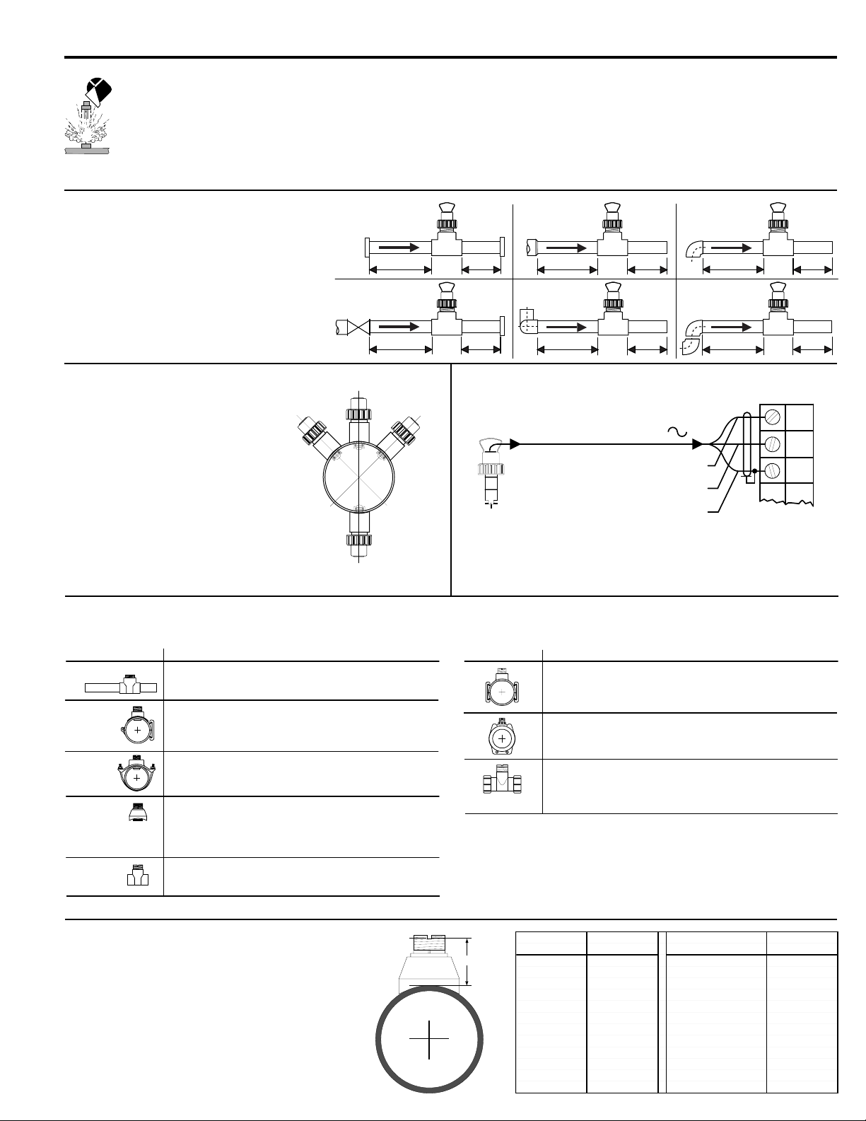
1. Location of Fitting
Recommended sensor upstream/downstream
mounting requirements
2. Sensor Mounting Position
• Horizontal pipe runs: Mount sensor in
the upright (0°) position for best overall
performance. Mount at a maximum of
45° when air bubbles are present. Do not
mount on the bottom of the pipe when
sediments are present.
• Vertical pipe runs: Sensor must be
mounted in lines with UPWARD flow only.
-45°
Flange
10x I.D. 5x I.D.
Valve/Gate
50x I.D. 5x I.D.
0°
Inlet
Process
Pipe
Outlet
Reducer
15x I.D. 5x I.D.
2 x 90° Elbow
3 dimensions
90° Elbow
20x I.D. 5x I.D.
2 x 90° Elbow
40x I.D. 5x I.D.
25x I.D. 5x I.D.
3. Sensor Wiring
+45°
FP-5100/FP-5300 Series Sensors
black (AC signal out)
red (AC signal out)
silver (shield)
Technical Notes
• Use 2-conductor shielded cable for cable extensions up to 60 m (200 ft).
• Cable shield must be maintained through cable splice.
• Refer to your instrument manual for specific wiring details.
Blk
F-
Red
F+
Shld
Instrument
4. OMEGA Fittings
Type Description
Plastic tees
PVC glue-on
saddles
(O-ring not
required)
Iron
strap-on
saddles
Carbon steel
weld-on
weldolets
Carbon steel
threaded tees
• 0.5 to 4 in. versions
• PVC or CPVC
• Mounts via glue-on fittings
• 2 to 4 in., cut 1-7/16 in. hole in pipe
• 6 to 8 in., cut 2-1/4 in. hole in pipe
• Align wedge arrows with saddle arrows during assembly.
• Pipes over 8 in., use iron saddle
• 2 to 4 in., cut 1-7/16 in. hole in pipe
• Over 4 in., cut 2-1/4 in. hole in pipe
• Special order over 12 in.
• 2 to 4 in., cut 1-7/16 in. hole in pipe.
• Over 4 in., cut 2-1/4 in. hole in pipe
• Remove insert before welding
• Installed by certified welder only
• Special order over 12 in.
• 0.5 to 2 in. versions
• Mounts on threaded pipe ends
5. H-Dimensions
The plastic sensor insert in the Weldolet fitting MUST be
removed during the welding process. When reinstalled, it is
important that the insert be threaded to the proper height
("H" dimension).
Type Description
Metric plastic saddle
• For pipes DN 65 to 200 mm
• Requires a 30 mm diam. hole in the pipe
• Wedge and saddle arrows must match
Metric wafer fitting
• For pipes DN 65 to 200 mm
• Follow the recommended installation guidelines
Metric union fitting
• For pipes from DN 15 to 50 mm
• PP or PVDF
• Follow the recommended installation guidelines
Weldolet "H" dimension Weldolet "H" dimension
part number inch mm part number inch mm
"H"
FP-5325CS 2.33 59.18 FP-5387CS 4.16 105.66
FP-5330CS 2.32 58.92 FP-5388CS 4.10 104.14
FP-5340CS 2.30 58.42
FP-5350CS 3.09 78.48
FP-5360CS 2.96 75.18 FMG-5325, FP-5325BR 2.33 59.18
FP-5380CS 2.73 69.34 FMG-5330, FP-5330BR 2.32 58.92
FP-5381CS 5.48 139.19 FMG-5340, FP-5340BR 2.30 58.42
FP-5382CS 5.25 133.35 FMG-5350, FP-5350BR 3.09 78.4
FP-5383CS 5.10 129.54 FMG-5360, FP-5360BR 2.96 75.1
FP-5384CS 4.85 123.19 FMG-5380, FP-5380BR 2.73 69.3
FP-5385CS 4.60 116.84 FMG-5381, FP-5381BR 5.48 139.1
FP-5386CS 4.38 111.25 FMG-5382, FP-5382BR 5.25 133.3
Page 4
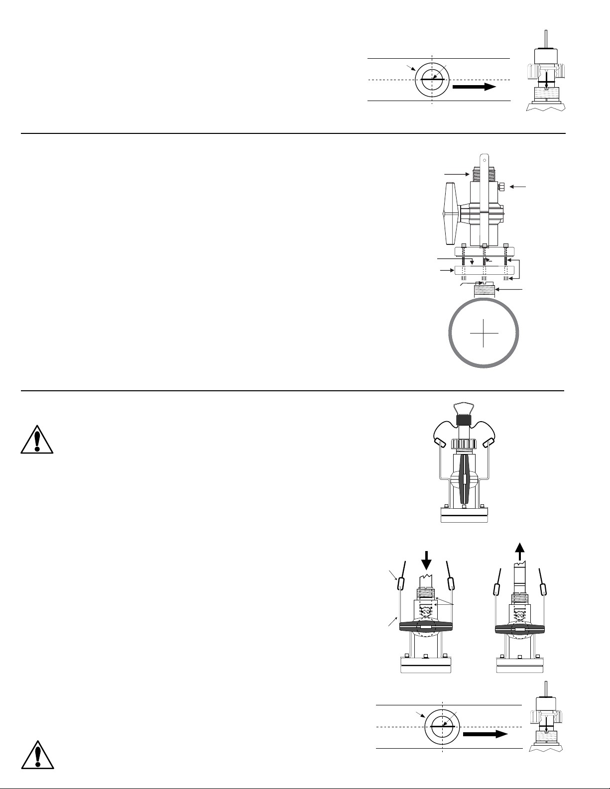
6. Standard Sensor Installation
safety
clamps
safety
lanyards
cable
brackets
o-rings
cable
clamps
safety
cables
cable
brackets
1. Lubricate the sensor O-rings with a silicone lubricant (e.g. GE silicone compound #G632 or
equivalent). Do not use any petroleum based lubricant that will attack the O-rings.
Figure B
Figure A
2. Using an alternating/twisting motion, lower the sensor into the fitting, making sure the installation
arrows on the black cap are pointing in the direction of flow, see Figure A.
3. Engage one thread of the sensor cap then turn the sensor until the alignment tab is seated in the
fitting notch. Hand tighten the sensor cap. DO NOT use any tools on the sensor cap or the cap
threads and/or fitting flange threads will be damaged, see Figure B.
7. Wet-Tap Installation
The OMEGA FP-319X Wet-Tap Assembly attaches directly onto any FP-53XX or FMG-53XX fitting to enable
sensor removal without system shutdown. It consists of a flange and support plate which thread onto the
pipe fitting insert, and a PVC ball valve through which an extended length sensor is inserted into the pipe.
Procedure
1. Remove six hex nuts and bolts from the Wet-Tap flange. Separate the support plate from the main
assembly. Be sure that the Viton O-ring is properly seated in the support plate groove.
2. Apply sealant to the pipe fitting insert threads to prevent leaks.
3. Screw support plate onto pipe fitting insert. It must be threaded completely down until the notches at
the top of the pipe fitting insert are exposed.
4. Mount the main Wet-Tap Assembly on the support plate. Make certain the alignment keys on the flange
mate with the notches on the pipe fitting insert.
5. Replace the six hex nuts and bolts to secure the Wet-Tap Assembly in place. Adjust the support plate
position as necessary to align screws.
6. Check the pressure relief plug on Wet-Tap Assembly. It must closed be finger tight to prevent leaks.
sensor cap
process pipe
(top view)
1-1/4 X 11-1/2 in.
NPSM thread
Valve handle
(shown in
open position)
Viton O-ring
Support plate
Align notch and key
under wet tap flange
parallel with pipe.
sensor bale
direction of flow
Key
Pressure
relief plug
Allen bolts
and hex nuts
Sealant
7. Close ball valve by turning the orange handle to the fully closed position (parallel with pipe).
8. Wet-Tap Sensor Installation
The FP-319X Wet-Tap Assembly allows installation into pressurized pipes without system
shutdown. OMEGA recommends reducing flow system pressure to 25 psi or less during
sensor installation in a pressurized pipe.
Non-Pressurized Installation
Open the orange ball valve handle to the full open position. Follow the steps 1-3 outlined in section 6.
Attach the cable clamps and safety cables to the cable brackets. Verify the relief valve is closed before
system operation, see Figure C.
Pressurized Installation
1. Lubricate the sensor O-rings with a silicone lubricant (e.g. GE silicone compound #G632 or
equivalent). Do not use any petroleum based lubricant that will attack the O-rings.
2. Being careful not to bump the sensor rotor against the closed ball valve orifice, gently insert the
extended sensor into the assembly until the first two O-rings seat inside the bore, see
Figure D.
3. Attach the cable clamps on each of the sensor's safety cables to the assembly cable brackets (Hand
tighten only), see Figure D.
4. Pull the flow sensor upward to remove slack in the safety cables, see Figure E
5. Reduce system pressure to 25 psi or less.
Figure C
Figure D
Figure E
6. Wearing safety face protection, slowly open the ball valve to the full open position (perpendicular to
pipe).
7. Using an alternating/twisting motion, push the extended sensor into the assembly, making sure the
sensor's installation decal is pointing in the direction of flow and the alignment tab seats into the fitting
notch, see Figure F. Align the tab under the red sensor cap in the notches on the fitting insert. Hand
tighten the red sensor cap, see Figure G. DO NOT use any tools on the red sensor cap or the cap
threads and/or fitting flange threads will be damaged.
CAUTION: Maximum FP-319X Wet-Tap operating pressure: 7 bar (100 psi) @
20 °C (68 °F) Maximum sensor installation/removal pressure: 1.7 bar (25 psi) @
22 °C (72 °F)
sensor cap
process pipe
(top view)
Figure F
sensor bale
direction of flow
Figure G
Page 5

9. K-Factors
The K-Factor is the number of pulses the sensor will generate for each engineering unit of fluid which passes. They are listed in U.S. gallons and in liters. For
example, in a 1 inch PVC pipe, the paddlewheel generates 176.670 pulses per gallon of fluid passing the rotor. K-factors are listed for pipes up to 12 inch. For
pipes over 12 inch, please contact OMEGA.
PIPE OMEGA --------KK--FFAACCTTOORR--------PIPE OMEGA --------KK--FFAACCTTOORR--------PIPE OMEGA --------KK--FFAACCTTOORR------SIZEFITTING TYPE U.S. GAL LITERS SIZE FITTING TYPE U.S. GAL LITERS SIZE FITTING TYPE U.S. GAL LITERS
SCH 80 PVC TEES FOR SCH 80 PVC PIPE GALVANIZED IRON TEES ON SCH 40 PIPE COPPER/BRONZE BRAZOLETS ON SCH 40 PIPE
1/2 IN. FP-5305 480.190 126.867 1 IN. FP-5310GI 104.538 27.619 2 1/2 IN. FP-5325BR 18.800 4.967
3/4 IN. FP-5307 257.720 68.090 1 1/4 IN. FP-5312GI 62.979 16.639 3 IN. FP-5330BR 12.170 3.215
1 IN.FP-5310 174.670 46.148 1 1/2 IN. FP-5315GI 46.688 12.335 4 IN. FP-5340BR 6.960 1.839
1 1/4 IN. FP-5312 83.390 22.032 2 IN. FP-5320GI 29.459 7.783 5 IN. FP-5350BR 5.260 1.390
1 1/2 IN. FP-5315 58.580 15.477 6 IN. FP-5360BR 3.690 0.975
2 IN.FP-5320 32.480 8.581
2 1/2 IN. FP-5325 21.833 5.768 1 IN. FP-5310BR 104.538 27.619 10 IN. FP-5381BR 1.350 0.357
3 IN.FP-5330 13.541 3.578 1 1/4 IN. FP-5312BR 62.979 16.639 12 IN. FP-5382BR 0.960 0.254
4 IN.FP-5340 7.626 2.015 1 1/2 IN. FP-5315BR 46.688 12.335
SCH 80 CPVC TEES FOR SCH 80 CPVC PIPE 2 IN. FP-5320GIS 32.360 8.550
1/2 IN. FP-5305C 480.190 126.867
3/4 IN. FP-5307C 257.720 68.090 1/2 IN.SK K FP-5305CU 443.206 117.095 3 IN. FP-5330GI 13.420 3.546
1 IN. FP-5310C 174.670 46.148 1/2 IN. SK L 414.413 109.488 4 IN. FP-5340GI 7.660 2.024
1 1/4 IN. FP-5312C 83.390 22.032 3/4 IN.SK K FP-5307CU 212.156 56.052 5 IN. FP-5350GI 5.860 1.548
1 1/2 IN. FP-5315C 58.580 15.477 3/4 IN. SK L 191.086 50.485 6 IN. FP-5360GI 4.090 1.081
SCH 80 PVC SADDLES FOR SCH 80 PVC PIPE 1 IN. SK L 119.840 31.662 10 IN. FP5381GI 1.530 0.404
2 IN. FP-5320S 32.480 8.581 1 1/4 IN.SK K FP-5312CU 88.218 23.307 12 IN. FP-5382GI 1.060 0.280
2 1/2 IN. FP-5325S 21.833 5.768 1 1/4 IN. SK L 85.451 22.576
3 IN. FP-5330S 13.541 3.578 1 1/2 IN.SK K FP-5315CU 56.962 15.049
4 IN. FP-5340S 7.626 2.015 1 1/2 IN. SK L 55.160 14.573 2 IN. FP-5320GIS 26.820 7.086
6 IN. FP-5360 4.162 1.100 2 IN.SK K FP-5320CU 29.370 7.759 2 1/2 IN. FP-5325GI 18.800 4.967
8 IN. FP-5380 2.370 0.626 2 IN. SK L 28.605 7.558 3 IN. FP-5330GI 11.990 3.168
SCH 80 PVC SADDLE ON SCH 40 PVC PIPE STAINLESS STEEL WELDOLETS ON SCH 40 PIPE 5 IN. FP-5350GI 5.330 1.408
2 IN. FP-5320S 27.350 7.226 2 1/2 IN. FMG-5325 18.800 4.967 6 IN. FP-5360GI 3.760 0.993
2 1/2 IN. FP-5325S 18.874 4.987 3 IN. FMG-5330 12.170 3.215 8 IN. FP-5380GI 2.130 0.563
3 IN. FP-5330S 12.638 3.339 4 IN. FMG-5340 6.960 1.839 10 IN. FP-5381GI 1.350 0.357
4 IN. FP-5340S 6.728 1.778 5 IN. FMG-5350 5.260 1.390 12 IN. FP-5382GI 0.960 0.254
6 IN. FP-5360 3.730 0.985 6 IN. FMG-5360 3.690 0.975
8 IN. FP-5380 2.153 0.569 8 IN. FMG-5380 2.130 0.563
CARBON STEEL TEES ON SCH 40 PIPE 12 IN. FMG-5382 0.960 0.254
1/2 IN. FP-5305CS 370.202 97.808
3/4 IN. FP-5307CS 212.063 56.027
1 IN. FP-5310CS 141.138 37.289 2 1/2 IN. FP-5325CS 18.800 4.967
1 1/4 IN. FP-5312CS 60.655 16.025 3 IN. FP-5330CS 12.170 3.215
1 1/2 IN. FP-5315CS 45.350 11.982 4 IN. FP-5340CS 6.960 1.839
2 IN. FP-5320CS 26.767 7.072 5 IN. FP-5350CS 5.260 1.390
STAINLESS STEEL TEES ON SCH 40 PIPE 8 IN. FP-5380CS 2.130 0.563
1/2 IN. FMG-5305 358.960 94.838 10 IN. FP-5381CS 1.350 0.357
3/4 IN. FMG5307 202.610 53.530 12 IN. FP-5382CS 0.960 0.254
1 IN. FMG5310 127.140 33.590
1 1/4 IN. FMG-5312 61.910 16.357
1 1/2 IN. FMG-5315 40.410 10.676
2 IN. FMG-5320 22.300 5.892
BRONZE TEES ON SCH 40 PIPE 8 IN.FP-5380BR 2.130 0.563
2 IN.FP-5320BR 29.459 7.783
COPPER TEE FITTINGS ON COPPER PIPE PIPE 2 1/2 IN. FP-5325GI 22.220 5.871
1 IN.SK K FP-5310CU 127.176 33.600 8 IN. FP-5380GI 2.330 0.616
SCH 80 IRON SADDLES ON SCH 80 PIPE
SCH 80 IRON SADDLE ON SCH 40 PIPE
4 IN. FP-5340GI 6.850 1.810
Conversion Formulas
1 U.S. gallon = 0.003785 cubic meters
10 IN. FMG-5381 1.350 0.357
0.000003069 Acre feet
8.3454 pounds of water
CARBON STEEL WELDOLETS ON SCH 40 PIPE
6 IN. FP-5360CS 3.690 0.975
-
K-Factors DIN Pipes
PIPE OMEGA --------KK--FFAACCTTOORR--------PIPE OMEGA --------KK--FFAACCTTOORR------SIZE FITTING TYPE U.S. GAL LITERS SIZE FITTING TYPE U.S. GAL LITERS
POLYPROPYLENE FITTINGS (DIN/ISO AND BS AND ANSI) PVDF FITTINGS (DIN/ISO AND BS AND ANSI)
DN 15 FP-5105PO 481.553 127.227 DN 15 FP-5105 420.868 111.194
DN 20 FP-5107PO 277.089 73.207 DN 20 FP-5107 228.149 60.277
DN 25 FP-5110PO 141.181 37.300 DN 25 FP-5110 136.697 36.116
DN 32 FP-5112PO 83.540 22.071 DN 32 FP-5112 79.294 20.950
DN 40 FP-5115PO 51.265 13.544 DN 40 FP-5115 43.490 11.490
DN 50 FP-5120PO 29.596 7.819 DN 50 FP-5120 25.908 6.845
DN 65 FP-5125PO 20.658 5.458 DN 65 FP-5125 18.067 4.773
DN 80 FP-5130PO 13.330 3.522 DN 80 FP-5130 12.357 3.265
DN 100 FP-5140PO 8.708 2.301 DN 100 FP-5140 8.060 2.129
DN 125 FP-5150PO 5.067 1.339 DN 125 FP-5150 4.431 1.171
DN 150 FP-5160PO 3.689 0.975 DN 150 FP-5160 3.227 0.853
DN 200 FP-5180PO 2.040 0.539 DN 200 FP-5180 2.036 0.538
-
Page 6
10. Order Information
Standard Paddlewheel Flow Sensors All O-rings are Viton® Accessories for FP-5300/FP-5100
Order No.
FP-5300
FP-5301
FP-5302
FP-5100 PVDF (natural) Hastelloy C PVDF (natural) 0.5 to 4.0 in.
FP-5101 PVDF (natural) Hastelloy C PVDF (natural) 5.0 to 8.0 in.
FP-5102 PVDF (natural) Hastelloy C PVDF (natural) 10 to 36 in.
FP-5100-AP PVDF (natural) PVDF (natural) PVDF (natural) 0.5 to 4.0 in.
FP-5101-AP PVDF (natural) PVDF (natural) PVDF (natural) 5.0 to 8.0 in.
FP-5102-AP PVDF (natural) PVDF (natural) PVDF (natural) 10 to 36 in.
FP-319X Wet-Tap Assembly Rotor pin material is Titanium O-Rings Material FMK-51542 Sensor cap, PP
Including Extended Sensor
Order No. Valve Body Rotor Pipe Size FPP-1228-0021 Kalrez (natural) with PP cap
FP-3193
FP-3194
FP-3195 PVC Polypro. PVDF (black) 10 to 36 in.
FP-319X Wet-Tap Without Sensor
Order No.
FP-319 PVC 319 Wet-Tap
Extended Sensors for FP-319 Wet-Tap Rotor pin material is Titanium FP85NM Integral sensor mounting kit with 1/2 in. NPT ports
Order No.
FMK-515-3P3
FMK-515-3P4
FMK-515-3P5 Polypro. Titanium PVDF (black) 10 to 36 in. FP8503 Integral sensor, PVDF (natural) 0.5 to 4 inch
Sensor Order No. Order No.
Body
Polypro.
Polypro.
Polypro.
PVC Polypro.
PVC Polypro.
Material
Sensor
Body
Polypro.
Polypro.
Rotor Pin Rotor Pipe Size
Titanium PVDF (black) 0.5 to 4.0 in.
Titanium PVDF (black) 5.0 to 8.0 in.
Titanium PVDF (black) 10 to 36 in.
Sensor FPP-1224-0021 EPR FMK-31536-2 Fitting plug, PVDF
PVDF (black) 0.5 to 4.0 in.
PVDF (black) 5.0 to 8.0 in.
Description
Rotor Pin Rotor Pipe Size
Titanium PVDF (black) 0.5 to 4.0 in.
Titanium PVDF (black) 5.0 to 8.0 in.
Rotors Material
FMK-1538-2 PVDF (FP-5300) FMK-1546-1 Titanium
FMK-51545-1 PVDF (natural) rotor + pin FMK-1546-2 Hastelloy C
FMK-1538-4 Tefzel FMK-1546-3 Tantalum
3-0515.320-3 Tefzel with Fluoroloy G sleeve FMK-1546-4 Stainless steel
3-0515.320-2 PVDF (natural) with Fluoroloy G sleeve FMK-51545 Ceramic
3-0515.320-1 PVDF (black) with Fluoroloy G sleeve
Order No. Order No. Description
FPP-1220-0021 Viton® (standard) FMK-31536-1 Fitting plug, PP
Integral Sensor Accessories for OMEGA FP85-A Flow Transmitter
Order No. Description
FP85DM Integral sensor mounting kit with PG 13.5 ports
Order No. Description Pipe Size
FP8501 Integral sensor, Polypro. 0.5 to 4 inch
FP8502 Integral sensor, Polypro. 5 to 8 inch
(FP-5100 & FP5100-AP) FMK-51545-1 PVDF (natural) + rotor
Rotor Pin
Material
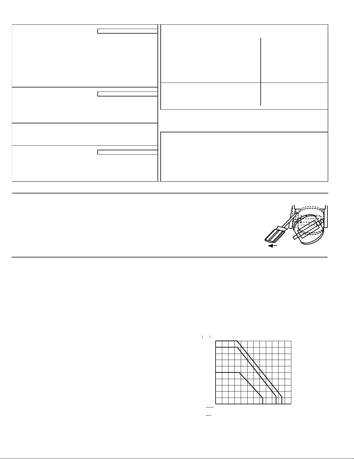
11. Rotor Replacement Procedure
1. To remove the rotor, insert a small screwdriver between the rotor and the ear of the sensor.
2. Twist the screwdriver blade to flex the ear outward enough to remove one end of the rotor and pin. DO NOT flex the ear
any more than necessary! If it breaks, the sensor cannot be repaired.
3. Install the new rotor by inserting one ear into the hole, then flex the opposite ear back enough to slip rotor into place.
12. Specifications
General Data
Flow Rate Range: 0.3 to 6 m/s (1 to 20 ft/s)
Linearity: ± 1% of maximum range
Repeatability: ±0.5% of maximum range
Pipe Size Range: 15 to 900 mm (0.5 to 36 in.)
Cable Length: 7.6 m (25 ft) can splice up to 60 m (200 ft) without
amplification
Cable type: 2-conductor twisted pair with shield
Materials
Sensor Assembly: Various thermoplastics available. Contact your OMEGA
dealer for additional information.
Electrical
Source Impedance: 8 kΩ
Fluid Conditions
Sensor Pressure/Temperature Ratings:
Polypropylene Body:
• 12.5 bar (180 psi) max. @ 20 °C (68 °F)
• 1.7 bar (25 psi) max. @ 90 °C (194 °F)
PVDF Body:
• 14 bar (200 psi) max. @ 20 °C (68 °F)
• 1.7 bar (25 psi) max. @ 100 °C (212 °F)
psi
bar
200
14
160
11
120
8
80
6
40
3
FP-319 W
FP-5100
5P-5300
et-Tap
°F
04080120 160 200
°C
-18 4
27
49
FP-319X Wet-Tap Assembly
Pressure/Temperature Ratings:
•7 bar (100 psi) max. @ 25 °C (77 °F)
• 1.4 bar (20 psi) max. @ 66 °C (150 °F)
71 93
240
115
Page 7

WARRANTY/DISCLAIMER
USA
ADE
IN
OMEGA ENGINEERING, INC. warrants this unit to be free of defects in materials and workmanship for a
period of 25 months from date of purchase. OMEGA Warranty adds an additional one (1) month grace
period to the normal two (2) year product warranty to cover handling and shipping time. This
ensures that OMEGA’s customers receive maximum coverage on each product.
If the unit should malfunction, it must be returned to the factory for evaluation. OMEGA’s Customer
Service Department will issue an Authorized Return (AR) number immediately upon phone or written
request. Upon examination by OMEGA, if the unit is found to be defective it will be repaired or replaced at
no charge. OMEGA’s WARRANTY does not apply to defects resulting from any action of the purchaser,
including but not limited to mishandling, improper interfacing, operation outside of design limits,
improper repair, or unauthorized modification. This WARRANTY is VOID if the unit shows evidence of
having been tampered with or shows evidence of being damaged as a result of excessive corrosion; or
current, heat, moisture or vibration; improper specification; misapplication; misuse or other operating
conditions outside of OMEGA’s control. Components which wear are not warranted, including but not
limited to contact points, fuses, and triacs.
OMEGA is pleased to offer suggestions on the use of its various products. However,
OMEGA neither assumes responsibility for any omissions or errors nor assumes liability for any
damages that result from the use of its products in accordance with information provided by
OMEGA, either verbal or written. OMEGA warrants only that the parts manufactured by it will be
as specified and free of defects. OMEGA MAKES NO OTHER WARRANTIES OR
REPRESENTATIONS OF ANY KIND WHATSOEVER, EXPRESSED OR IMPLIED, EXCEPT THAT OF
TITLE, AND ALL IMPLIED WARRANTIES INCLUDING ANY WARRANTY OF MERCHANTABILITY
AND FITNESS FOR A PARTICULAR PURPOSE ARE HEREBY DISCLAIMED. LIMITATION OF
LIABILITY: The remedies of purchaser set forth herein are exclusive and the total liability of
OMEGA with respect to this order, whether based on contract, warranty, negligence,
indemnification, strict liability or otherwise, shall not exceed the purchase price of the
component upon which liability is based. In no event shall OMEGA be liable for
consequential, incidental or special damages.
CONDITIONS: Equipment sold by OMEGA is not intended to be used, nor shall it be used: (1) as a “Basic
Component” under 10 CFR 21 (NRC), used in or with any nuclear installation or activity; or (2) in medical
applications or used on humans. Should any Product(s) be used in or with any nuclear installation or
activity, medical application, used on humans, or misused in any way, OMEGA assumes no responsibility
as set forth in our basic WARRANTY/ DISCLAIMER language, and additionally, purchaser will indemnify
OMEGA and hold OMEGA harmless from any liability or damage whatsoever arising out of the use of the
Product(s) in such a manner.
RETURN REQUESTS / INQUIRIES
Direct all warranty and repair requests/inquiries to the OMEGA Customer Service Department. BEFORE
RETURNING ANY PRODUCT(S) TO OMEGA, PURCHASER MUST OBTAIN AN AUTHORIZED RETURN
(AR) NUMBER FROM OMEGA’S CUSTOMER SERVICE DEPARTMENT (IN ORDER TO AVOID
PROCESSING DELAYS). The assigned AR number should then be marked on the outside of the return
package and on any correspondence.
The purchaser is responsible for shipping charges, freight, insurance and proper packaging to prevent
breakage in transit.
FOR W
following information available BEFORE
contacting OMEGA:
1. P.O. number under which the product was
2. Model and serial number of the product under
3. Repair instructions and/or specific problems
OMEGA’s policy is to make running changes, not model changes, whenever an improvement is possible. This affords
our customers the latest in technology and engineering.
OMEGA is a registered trademark of OMEGA ENGINEERING, INC.
© Copyright 1996 OMEGA ENGINEERING, INC. All rights reserved. This document may not be copied, photocopied,
reproduced, translated, or reduced to any electronic medium or machine-readable form, in whole or in part, without prior
written consent of OMEGA ENGINEERING, INC.
ARRANTY RETURNS, please have the
PURCHASED,
warranty, and
relative to the product.
FOR NON-WARRANTY REPAIRS,
consult OMEGA
for current repair charges. Have the following
information available BEFORE contacting OMEGA:
1. P.O. number to cover the COST
of the repair,
2. Model and serial number of product, and
3. Repair instructions and/or specific problems
relative to the product.
Page 8

Where Do I Find Everything I Need for
Process Measurement and Control?
OMEGA…Of Course!
TEMPERATURE
䡺⻬
Thermocouple, RTD & Thermistor Probes, Connectors, Panels & Assemblies
䡺⻬
Wire: Thermocouple, RTD & Thermistor
䡺⻬
Calibrators & Ice Point References
䡺⻬
Recorders, Controllers & Process Monitors
䡺⻬
Infrared Pyrometers
PRESSURE, STRAIN AND FORCE
䡺⻬
Transducers & Strain Gauges
䡺⻬
Load Cells & Pressure Gauges
䡺⻬
Displacement Transducers
䡺⻬
Instrumentation & Accessories
FLOW/LEVEL
䡺⻬
Rotameters, Gas Mass Flowmeters & Flow Computers
䡺⻬
Air Velocity Indicators
䡺⻬
Turbine/Paddlewheel Systems
䡺⻬
Totalizers & Batch Controllers
pH/CONDUCTIVITY
䡺⻬
pH Electrodes, Testers & Accessories
䡺⻬
Benchtop/Laboratory Meters
䡺⻬
Controllers, Calibrators, Simulators & Pumps
䡺⻬
Industrial pH & Conductivity Equipment
DATA ACQUISITION
䡺⻬
Data Acquisition & Engineering Software
䡺⻬
Communications-Based Acquisition Systems
䡺⻬
Plug-in Cards for Apple, IBM & Compatibles
䡺⻬
Datalogging Systems
䡺⻬
Recorders, Printers & Plotters
HEATERS
䡺⻬
Heating Cable
䡺⻬
Cartridge & Strip Heaters
䡺⻬
Immersion & Band Heaters
䡺⻬
Flexible Heaters
䡺⻬
Laboratory Heaters
ENVIRONMENTAL
MONITORING AND CONTROL
䡺⻬
Metering & Control Instrumentation
䡺⻬
Refractometers
䡺⻬
Pumps & Tubing
䡺⻬
Air, Soil & Water Monitors
䡺⻬
Industrial Water & Wastewater Treatment
䡺⻬
pH, Conductivity & Dissolved Oxygen Instruments
P51590-OM/(K-12/01) M-1931/1201
 Loading...