

Page 1

User’s Guide
Shop online at
omega.com
e-mail: [email protected]
For latest product manuals:
www.omegamanual.info
SM
FP-5070 SERIES
Flow Sensors
Page 2

omega.com [email protected]
Servicing North America:
U.S.A. Omega Engineering, Inc.
Headquarters: Toll-Free: 1-800-826-6342 (USA & Canada only)
Customer Service: 1-800-622-2378 (USA & Canada only)
Engineering Service: 1-800-872-9436 (USA & Canada only)
Tel: (203) 359-1660 Fax: (203) 359-7700
e-mail: [email protected]
For Other Locations Visit omega.com/worldwide
The information contained in this document is believed to be correct, but OMEGA accepts no liability for any errors it contains, and reserves
the right to alter specifications without notice.
Page 3
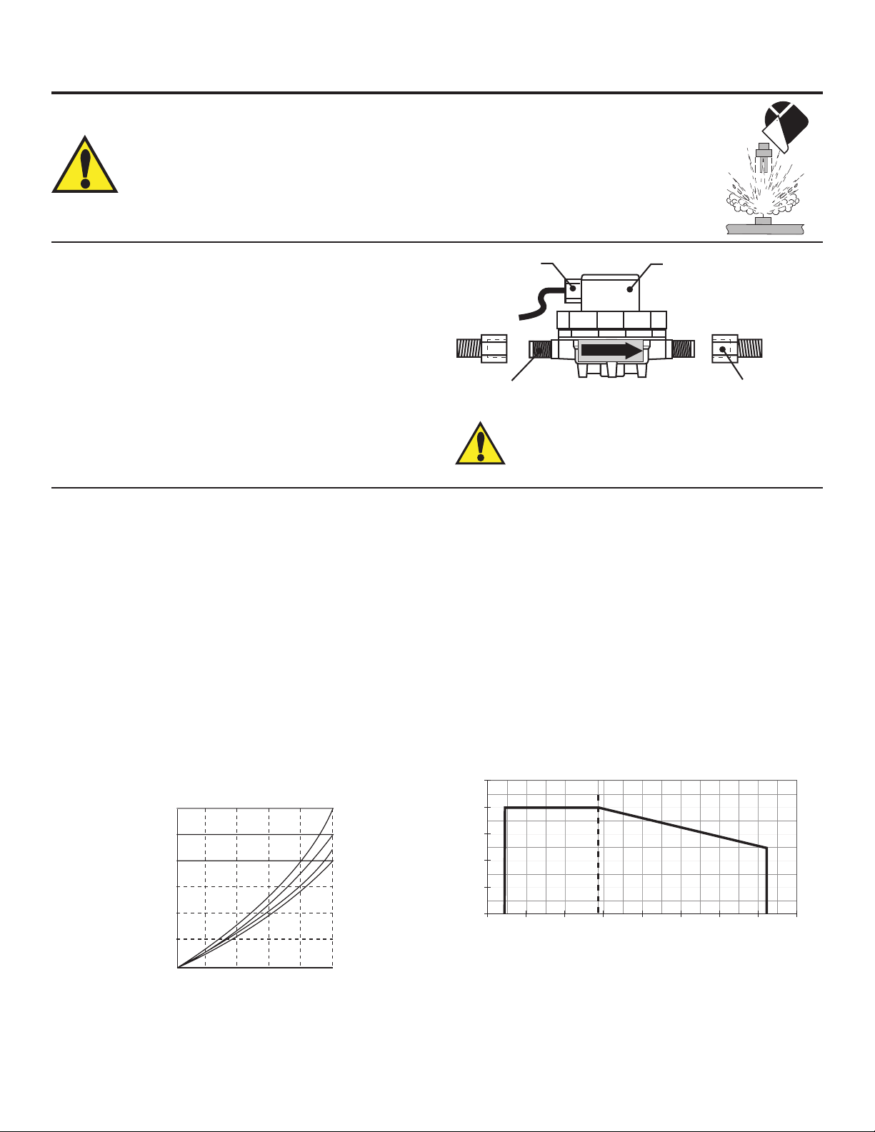
OMEGAFP-5070SeriesFlowSensors
FLOW
Cable plug
25 ft cable
Pipe fitting adapter
G
1
/4 x 1/4 in. NPT
G
1
/4 in.
port threads
Upper body with
electronic switch
Lower body with
built-in rotor
psibar
6.9 100
5.5 80
4.1 60
2.8 40
1.4 20
0
-40
-400-18
4048027120491607120093240
116
280
138°F°C
02040607080
0.25
0.50
0.75
1.00
1.25
1.50
3.63
7.25
10.88
14.50
18.13
21.76
PSI
BAR
Flow rate (%) of full scale
Pressure Drop Across Sensor vs. Flow Rate
-2V
-3V
-4V
-6V
SAFETY INSTRUCTIONS
WARNING!
1. Description
The FP-5070 Series Mini Flow Sensors contain a free-running
rotor which is driven by the uid ow. Within the given
measurement range, the rotational speed of the rotor is
proportional to the uid ow rate. Permanent magnets built into
the rotor actuate an electronic switch in the top of the sensor
generating a square-wave output signal proportional to ow rate.
Both opaque and transparent uids can be measured from 0.2 to
20.0 centistokes.
1. Do not remove from pressurized lines.
2. Do not exceed maximum temperature/pressure specications.
3. Pipe tting must be installed by certied welder only.
4. Do not install/service without following installation instructions (see sensor manual).
5. Wear safety goggles and face shield during installation/service.
6. Do not alter product construction.
7. Failure to follow safety instructions could result in severe personal injury!
Wetted sensor parts are constructed of PVDF and FPM, making
the sensor suitable for use with most process uids, including most
acids, bases, light oils, and solvents.
2. Specications
General
Flow Range:
• -2V sensor:..........400 to 2800 mL/m (0.105 to 0.740 U.S. gpm)
• -4V sensor:..........1300 to 6000 mL/m (0.343 to 1.585 U.S. gpm)
• -6V sensor:..........3200 to 12000 mL/m (0.845 to 3.170 U.S. gpm)
Linearity: .................±0.25% of full range
Repeatability: ..........±0.25% of full range
Viscosity range: ......0.2 to 20.0 centistokes
Pipe connections: ...G 1/4 in. ports, 1/4 in. NPT (male) pipe adapters
(2 included)
Cable length: ..........Std: 7.6m (25 ft), max.: 300 m (1000 ft)
Cable type: .............2-conductor shielded, twisted-pair, 22 AWG
Shipping Weight: ....0.4 kg (0.8 lb)
WARNING!
Polar organic solvents (e.g., ketones and chlorinated
hydrocarbons) and aromatic hydrocarbons are not
compatible with this sensor.
WettedMaterials
• Housing: ......................PVDF
• Flow insert:..................PTFE
• Quad ring seal:............FPM
• Rotor: ..........................PVDF
• Pipe thread adapters:..PVDF
• Suitable for clean uids only
Electrical
Power: ...........................5 to 24 VDC ±10%, regulated,
10 mA max.
Output Type: ..................Open-collector, sinking, 10 mA max.
Max.Temperature/PressureRating
• 5.5 bar @ -30 °C (80 psi @ -22 °F)
• 5.5 bar @ 24 °C (80 psi @ 75 °F)
• 3 bar @ 120 °C (45 psi @ 248 °F)
Omega FP-5070 Series Flow Sensors
StandardsandApprovals
• CE
• Manufactured under ISO 9001
1
Page 4
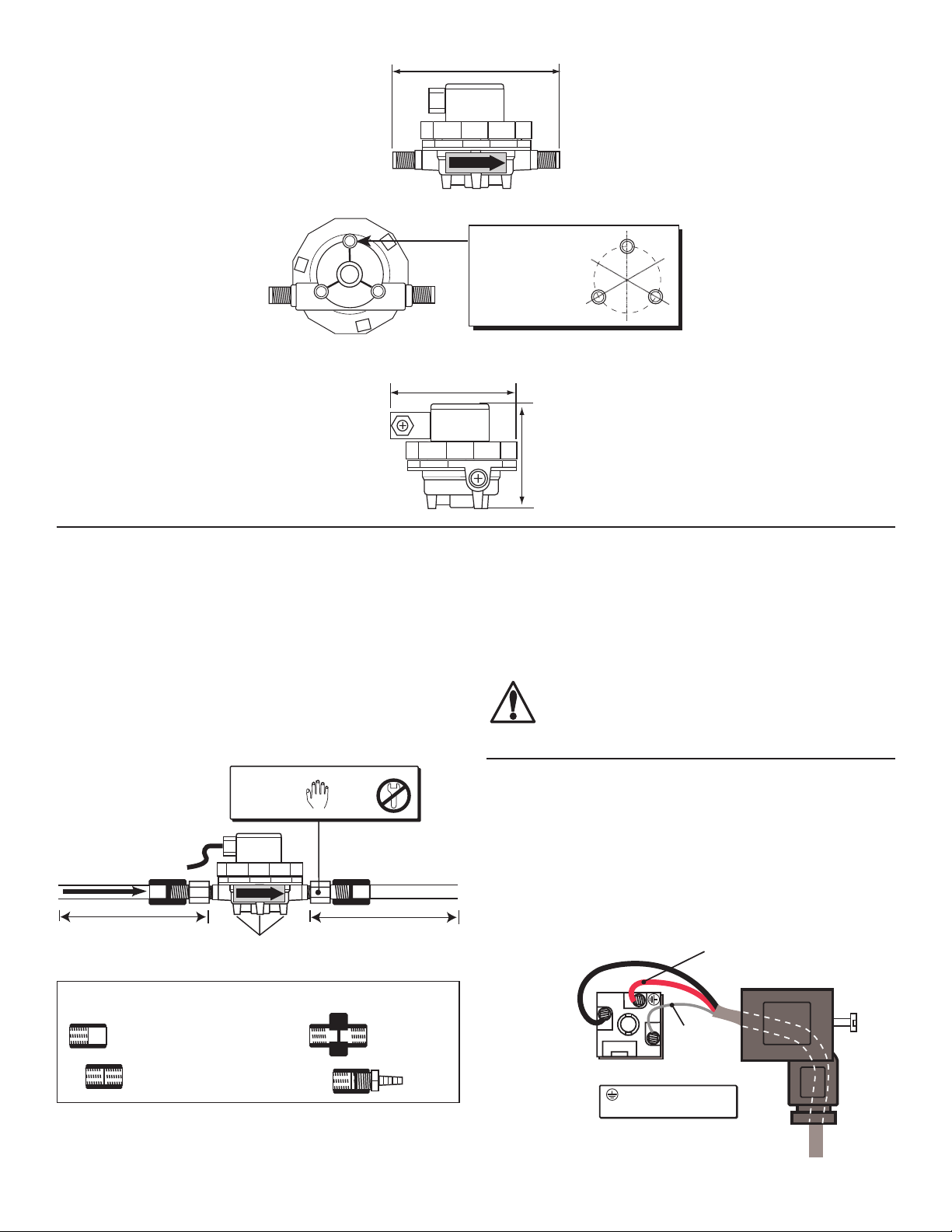
1
2
Sensor
Ground
(silver wire)
Sensor Power:
5 to 24 VDC
(black wire)
Sensor Signal Output
(Red wire)
Max cable length:
300 m (1000 ft)
Sensor
Plug (side)
Disregard ground
symbol on connector
95 mm (3.74 in.)
Dimensions:
FLOW
68 mm (2.7 in.)
Mounting tabs (3),
#8 or M4 self-tapping
screws required
(customer supplied)
32.5 mm (1.28 in.)
bolt circle
65 mm
(2.6 in.)
3. Installation
• The sensor may be installed in any position, although horizontal
ow is recommended (the sensor mounted upright). If the
sensor is not installed upright, the linearity error may be greater
in the lower part of the sensor's measurement range.
• Mounting tabs are provided using M4 or #8 self-tapping screws
(customer supplied). See Dimensions illustration for mounting
tab hole pattern specications.
• Install sensor with the arrow pointing in the direction of ow.
• Always maximize distance between the sensor and pump
source. Never install immediately downstream of valves,
FLOW
100 to 150 mm (4 to 6 in.)
Compatible pipe/tubing connections (customer supplied):
InstallationHints
• Avoid vibrations and shocks.
• Avoid solids in the uid.
• Install a lter or line strainer upstream to protect sensor.
Female SxT
coupling
Female TxT
coupling
Pipe Fitting
Adapters
(included)
FLOW
Mounting
tabs (3)
100 to 150 mm (4 to 6 in.)
Female TxT
coupling
Hand
tighten
only!
Coupling
Pipe or
tubing
Female TxT
union
Hose
adapter
ttings, etc. For optimum performance, a straight ow run of at
least 100 mm to 150 mm (4 to 6 in.) should be provided before
and after the sensor.
• Two pipe tting adapters (included) convert the G 1/4 in.
straight threads to 1/4 in. NPT pipe threads. Handtighten
only! Apply 1-2 turns of PTFE sealing tape to all threaded
connections to prevent leaks.
CAUTION!
Use an adjustable wrench to prevent the tting
adapters from overtightening while installing mating
pipe connectors. Sensor damage will occur if the ports
are overtightened.
4. WiringDetails
4.1 CableExtensions
The standard 25 foot sensor cable can be extended to 300 m
(1000 ft) using 2-conductor shielded twisted-pair cable.
• Always maintain cable shield through cable splice.
• For splice-free cable replacement up to 300 m (1000 ft), refer
to the sensor plug connection diagram (below) for connection
details.
2
Omega FP-5070 Series Flow Sensors
Page 5
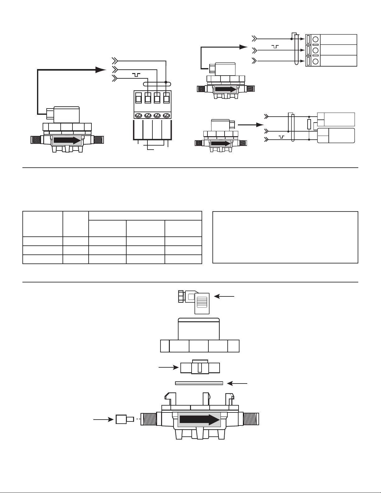
4.2InstrumentConnections
Black
Shield
Sensor
Red
FLOW
FP-5072
OMEGA
FP-90 Series
Sensr Gnd
(SHIELD)
Sensr IN
(RED)
Sensr V+
(BLACK)
9
8
7
FLOW
OMEGA
FPM-5500/FPM-9020A
Black
Shield
additional information.
Red
Black
Shield
Freq. IN
Sen. Pwr.
Freq. IN
Iso. Gnd
Open Collector
Sensor
Std. Sensor
Red
FLOW
FP-5072
FP-5072
OMEGA
FP-90 Series
Sensr Gnd
(SHIELD)
Sensr IN
(RED)
Sensr V+
(BLACK)
9
8
7
Flow inserts:
2 mm: #3-2507.081-2
3 mm: #3-2507.081-3
4 mm: #3-2507.081-4
Quad ring seal,
Cable plug,
OMEGA
FPM-5500/FPM-9020A
Shield
Black
Red
FP-5072
FLOW
Shield
Red
Black
Sensr Gnd
9
(SHIELD)
Sensr IN
8
(RED)
Sensr V+
7
(BLACK)
OMEGA
FP-90 Series
FP-5072
External Power supply
5 to 24
+
VDC
-
Gnd.
Other
instrument
Input
FLOW
Std. Sensor
Freq. IN
Freq. IN
Iso. Gnd
Sen. Pwr.
Open Collector
FP-5072
FLOW
• Pull-up resistor required (10 kΩ recommended). Consult your instrument manual for
Black
Shield
Red
10k Ω
5. Calibration
The K-Factors listed here represent the number of pulses the sensor will generate for each measured engineering unit. They are listed
in U.S. gallons, liters and milliliters (mL) for each sensor model.
Sensor
Model
FP-5072-PV 2 mm 5685 1502 1.502
FP-5074-PV 4 mm 2316 612 0.612
FP-5076-PV NONE 1249 330 0.330
6. ReplacementParts
Insert
Flow
K-FACTORS
Pulsesper
Pulsesper
U.S. GAL
Rotor,
#3-2507.080-2
LITER
Pulsesper
mL
IMPORTANT!
• K-Factors must be considered as approximate
values.
• The number of pulses per volumetric unit may vary
depending on the medium and the installation.
• For optimum performance, the system must be
calibrated after installation.
#3-2507.080-5
Upper body
#3-2507.080-3
Omega FP-5070 Series Flow Sensors
FLOW
Lower Body,
3-2507.080-4x
(x = size of flow insert)
3
Page 6
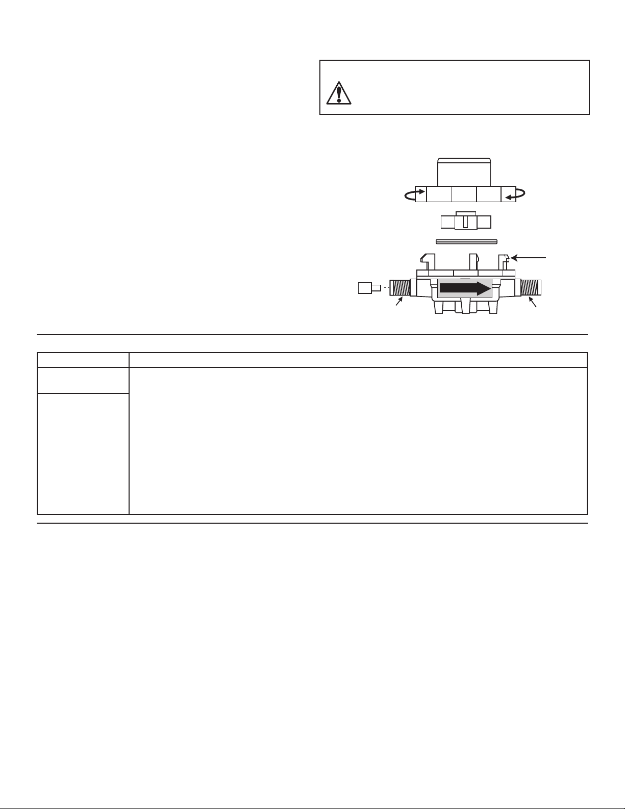
Assemble
(counterclockwise)
Disassemble
(clockwise)
Upper body
Lower Body
Assembly
Tabs (3)
FLOW
Inlet port
Outlet port
flow
insert
Rotor
Quad ring seal
7. ReplacingTheFlowInsert
Sensor range can be modied by changing the ow insert. The
sensor must be removed from service and disassembled prior to
installing the new ow insert. See Specications (Section 2) for
ow range data.
FlowInsertReplacementProcedure:
1. Depressurize system and remove sensor.
2. Rotate the upper sensor body clockwise until it releases from
the lower half, then lift off.
3. Remove rotor and quad ring seal from lower body.
4. Push the ow insert outward using a small screwdriver.
5. Install the new ow insert (small diameter inward) with the
eraser end of a pencil. Apply light pressure until insert seats
against the step in the lower body. Donotforce!
6. Install rotor into lower body. Spin rotor with nger and check
for free rotation. If rotor hits ow insert, remove rotor and
push insert back until free rotor rotation is established. Use
a rounded object such as a pen or pencil body to adjust ow
insert depth.
7. Install rotor, quad ring, and upper body. Handtightenonly!
Do not overtighten upper body or the lower body assembly
tabs will break.
8. Reprogram instrument with new K-Factor, see Calibration
(Section 5).
CAUTION!
Do not use tools of any kind on the sensor body or port
connections. Hand tighten only! Excessive force will
damage sensor.
Condition Recommendation
Erratic or missing
sensor signal
A. Verify ALL cable and instrument connections (section 4).
B. Verify proper sensor installation (section 3).
C. Remove power from instrument and disconnect sensor inputs. Apply power to the instrument and
check across Black and Shield terminals with a digital voltmeter for 5 VDC. If 5 VDC is not present, the
instrument requires service or may be miscongured.
Perform steps A - E.
If sensor problems
persist, contact
OMEGA.
D. Verify the FP-5072 paddlewheel spins freely by blowing into the ow chamber. If the paddlewheel does
not spin freely, the following conditions may exist:
• The sensor may be dirtty or clogged. Disassemble and clean with hot tap water and a soft brush (see
section 7).
• The rotor may be hitting the ow insert. Disassemble and adjust ow insert depth (see section 7).
E. Test sensor with ow system active and sensor powered. Use an oscilloscope to check the sensor input
signal across the Red (Signal IN) and Shield terminals. A square wave signal should appear at these
terminals. If no signal is present, replace sensor.
8. OrderingInformation
Mfr.PartNo. Description
FP-5072-PV Mini-Flow Sensor, 2 mm insert
FP-5074-PV Mini-Flow Sensor, 4 mm insert
FP-5076-PV Mini-Flow Sensor, 6 mm inlet, no insert
4
Omega FP-5070 Series Flow Sensors
Page 7

WARRANTY/DISCLAIMER
OMEGA ENGINEERING, INC. warrants this unit to be free of defects in materials and workmanship for a
period of 13 months from date of purchase. OMEGA’s WARRANTY adds an additional one (1) month
grace period to the normal one (1) year product warranty to cover handling and shipping time. This
ensures that OMEGA’s customers receive maximum coverage on each product.
If the unit malfunctions, it must be returned to the factory for evaluation. OMEGA’s Customer Service
Department will issue an Authorized Return (AR) number immediately upon phone or written request.
Upon examination by OMEGA, if the unit is found to be defective, it will be repaired or replaced at no
charge. OMEGA’s WARRANTY does not apply to defects resulting from any action of the purchaser,
including but not limited to mishandling, improper interfacing, operation outside of design limits,
improper repair, or unauthorized modification. This WARRANTY is VOID if the unit shows evidence of
having been tampered with or shows evidence of having been damaged as a result of excessive corrosion;
or current, heat, moisture or vibration; improper specification; misapplication; misuse or other operating
conditions outside of OMEGA’s control. Components in which wear is not warranted, include but are not
limited to contact points, fuses, and triacs.
OMEGA is pleased to offer suggestions on the use of its various products. However,
OMEGA neither assumes responsibility for any omissions or errors nor assumes liability for
any damages that result from the use of its products in accordance with information provided
by OMEGA, either verbal or written. OMEGA warrants only that the parts manufactured by the
company will be as specified and free of defects. OMEGA MAKES NO OTHER WARRANTIES OR
REPRESENTATIONS OF ANY KIND WHATSOEVER, EXPRESSED OR IMPLIED, EXCEPT THAT OF
TITLE, AND ALL IMPLIED WARRANTIES INCLUDING ANY WARRANTY OF MERCHANTABILITY
AND FITNESS FOR A PARTICULAR PURPOSE ARE HEREBY DISCLAIMED. LIMITATION OF
LIABILITY: The remedies of purchaser set forth herein are exclusive, and the total liability of
OMEGA with respect to this order, whether based on contract, warranty, negligence,
indemnification, strict liability or otherwise, shall not exceed the purchase price of the
component upon which liability is based. In no event shall OMEGA be liable for
consequential, incidental or special damages.
CONDITIONS: Equipment sold by OMEGA is not intended to be used, nor shall it be used: (1) as a “Basic
Component” under 10 CFR 21 (NRC), used in or with any nuclear installation or activity; or (2) in medical
applications or used on humans. Should any Product(s) be used in or with any nuclear installation or
activity, medical application, used on humans, or misused in any way, OMEGA assumes no responsibility
as set forth in our basic WARRANTY/DISCLAIMER language, and, additionally, purchaser will indemnify
OMEGA and hold OMEGA harmless from any liability or damage whatsoever arising out of the use of the
Product(s) in such a manner.
RETURN REQUESTS/INQUIRIES
Direct all warranty and repair requests/inquiries to the OMEGA Customer Service Department.
BEFORE RETURNING ANY PRODUCT(S) TO OMEGA, PURCHASER MUST OBTAIN AN AUTHORIZED
RETURN (AR) NUMBER FROM OMEGA’S CUSTOMER SERVICE DEPARTMENT (IN ORDER TO AVOID
PROCESSING DELAYS). The assigned AR number should then be marked on the outside of the return
package and on any correspondence.
The purchaser is responsible for shipping charges, freight, insurance and proper packaging to prevent
breakage in transit.
FOR WARRANTY RETURNS, please have the
following information available BEFORE contacting
OMEGA:
1. Purchase Order number under which the product
was PURCHASED,
2. Model and serial number of the product under
warranty, and
3. Repair instructions and/or specific problems
relative to the product.
OMEGA’s policy is to make running changes, not model changes, whenever an improvement is possible. This affords
our customers the latest in technology and engineering.
OMEGA is a registered trademark of OMEGA ENGINEERING, INC.
© Copyright 2016 OMEGA ENGINEERING, INC. All rights reserved. This document may not be copied, photocopied,
reproduced, translated, or reduced to any electronic medium or machine-readable form, in whole or in part, without the
prior written consent of OMEGA ENGINEERING, INC.
FOR NON-WARRANTY REPAIRS,
OMEGA for current repair charges. Have
the following information available BEFORE
contacting OMEGA:
1. Purchase Order number to cover the COST
of the repair,
2. Model and serial number of the product, and
3. Repair instructions and/or specific problems
relative to the product.
consult
Page 8

Where Do I Find Everything I Need for
Process Measurement and Control?
OMEGA…Of Course!
Shop online at omega.com
TEMPERATURE
MU
Thermocouple, RTD & Thermistor Probes, Connectors, Panels & Assemblies
MU
Wire: Thermocouple, RTD & Thermistor
MU
Calibrators & Ice Point References
MU
Recorders, Controllers & Process Monitors
MU
Infrared Pyrometers
PRESSURE, STRAIN AND FORCE
MU
Transducers & Strain Gages
MU
Load Cells & Pressure Gages
MU
Displacement Transducers
MU
Instrumentation & Accessories
FLOW/LEVEL
MU
Rotameters, Gas Mass Flowmeters & Flow Computers
MU
Air Velocity Indicators
MU
Turbine/Paddlewheel Systems
MU
Totalizers & Batch Controllers
SM
pH/CONDUCTIVITY
MU
pH Electrodes, Testers & Accessories
MU
Benchtop/Laboratory Meters
MU
Controllers, Calibrators, Simulators & Pumps
MU
Industrial pH & Conductivity Equipment
DATA ACQUISITION
MU Communications-Based Acquisition Systems
MU Data Logging Systems
MU Wireless Sensors, Transmitters, & Receivers
MU Signal Conditioners
MU Data Acquisition Software
HEATERS
MU
Heating Cable
MU
Cartridge & Strip Heaters
MU
Immersion & Band Heaters
MU
Flexible Heaters
MU
Laboratory Heaters
ENVIRONMENTAL
MONITORING AND CONTROL
MU
Metering & Control Instrumentation
MU
Refractometers
MU
Pumps & Tubing
MU
Air, Soil & Water Monitors
MU
Industrial Water & Wastewater Treatment
MU
pH, Conductivity & Dissolved Oxygen Instruments
6-2507.090-OM (Rev. L 01/17) M2972/0117
 Loading...