

Page 1
User’s Guide
Shop online at
omega.com
e-mail: [email protected]
For latest product manuals:
www.omegamanual.info
SM
FP-319
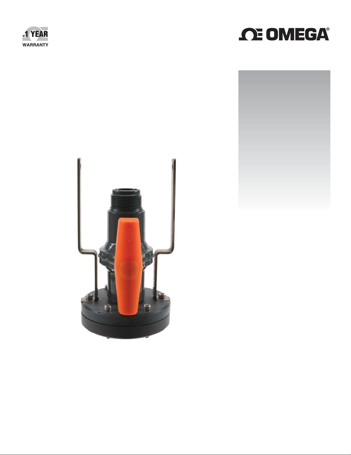
Flow Wet-Tap Assembly
Page 2

omega.com [email protected]
Servicing North America:
U.S.A. Omega Engineering, Inc.
Headquarters: Toll-Free: 1-800-826-6342 (USA & Canada only)
Customer Service: 1-800-622-2378 (USA & Canada only)
Engineering Service: 1-800-872-9436 (USA & Canada only)
Tel: (203) 359-1660 Fax: (203) 359-7700
e-mail: [email protected]
For Other Locations Visit omega.com/worldwide
The information contained in this document is believed to be correct, but OMEGA accepts no liability for any errors it contains, and reserves
the right to alter specifications without notice.
Page 3
OMEGA FP-319 Flow Wet-Tap Assembly
SAFETY INSTRUCTIONS
1. The FP-319 Flow Wet-Tap Valve may only be installed into, and removed from, non-pressurized
systems (0 psig).
2. The pressure must be reduced to 25 psi when removing or installing the sensor and must
maintain 25 psi or lower while the sensor is removed.
3. Stay clear of sensor stroke area and safety cable during sensor removal.
4. Confi rm chemical compatibility before use.
5. Do not exceed maximum temperature/pressure specifi cations.
6. Wear safety goggles or faceshield during installation/service.
7. Do not alter product construction.
Failure to follow safety precautions may result in severe personal injury!
1. Specifi cations
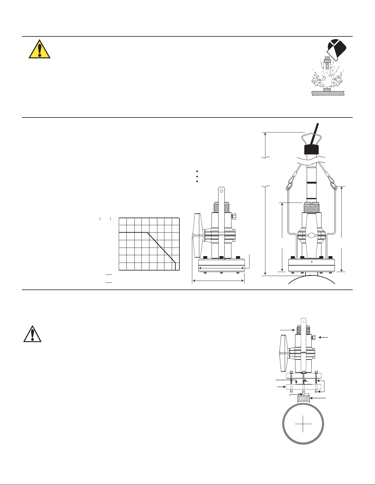
Dimensions
Materials
Body: PVC
Ball seat: PTFE
O-rings: FPM
Standards
• Manufactured under ISO 9001 and 14001
Fluid Conditions
Total minimum clearance for sensor insertion
and removal:
1/2 to 4 inch pipe: 737 mm (29 inches)
5 to 8 inch pipe: 762 mm (30 inches)
10 inch and up: 813 mm (32 inches)
Pressure/Temperature Ratings:
• 7 bar max. @ -18 to 20 °C
(100 psi max. @ 0 to 68 °F)
• 1.4 bar max. @ 66 °C
(20 psi max. @ 150 °F)
bar
8
6
3
°F
psi
120
80
40
0 40 80 120 160
-18 4 274971°C
FP-319 Wet-Tap
137 mm
(5.39 in.)
121 mm
(4.75 in.)
185 mm
(7.28 in.)
220 mm
(8.66 in.)
2. Wet-Tap Valve Installation
The OMEGA FP-319 Flow Wet-Tap Assembly attaches directly to OMEGA installation fi ttings to enable fl ow sensor removal without
system shutdown. It consists of a fl ange and support plate which thread onto the pipe fi tting insert, and a PVC ball valve through which
an extended length fl ow sensor is inserted into the pipe.
Caution: The FP-319 Flow Wet-Tap Valve may only be installed into, and
removed from, non-pressurized systems (0 psig).
Procedure
1. Remove six hex nuts and bolts from the Wet-Tap fl ange. Separate the support plate
from the main assembly. Be sure that the Viton O-ring is properly seated in the
support plate groove.
2. Apply sealant to the pipe fi tting insert threads to prevent leaks.
3. Screw support plate onto pipe fi tting insert (O-ring side facing up). It must be
threaded completely down until the notches at the top of the pipe fi tting insert are
exposed.
4. Mount the main Wet-Tap Assembly on the support plate. Make certain the
alignment keys on the fl ange mate with the notches on the pipe fi tting insert.
5. Loosen support plate (holding the main Wet-Tap Assembly in place) until it resists
slightly. Loosen an additional 1/4-turn to seat O-ring.
6. Replace the six hex nuts and bolts to secure the Wet-Tap Assembly in place. Adjust
the support plate position as necessary to align screws.
7. Check the pressure relief plug on Wet-Tap Assembly. It must be closed fi nger tight
to prevent leaks.
8. Close ball valve by turning the handle to the fully closed position (parallel with pipe).
1-1/4 X 11-1/2 in.
NPSM thread
Valve handle
(shown in
open position)
Viton O-ring
Support plate
Align notch and key
under wet tap flange
parallel with pipe.
Key
Pressure
relief plug
Allen bolts
and hex nuts
Sealant
1Omega FP-319 Flow Wet-Tap Assembly
Page 4
3. Flow Sensor Insertion/Removal
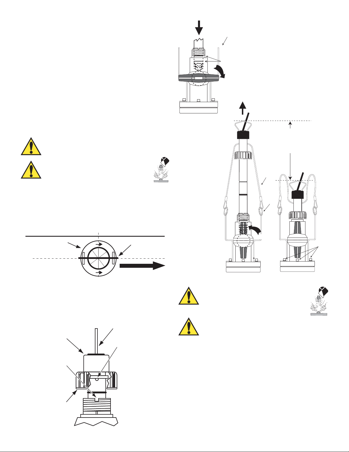
To insert the fl ow sensor:
1. Lubricate the sensor O-rings with a lubricant compatible
with your process and the sensor materials of construction.
Do not use petroleum based lubricants that will attack the
O-rings.
2. Carefully insert the sensor into the FP-319 valve assembly
until the fi rst two O-rings seat inside the bore (Figure 1).
• Do not damage the rotor on closed ball valve.
3. Using the clamps, attach the sensor safety cable to the
FP-319 assembly brackets (hand tighten only).
4. Pull the fl ow sensor upward to remove slack in the safety
cables (Figure 2).
WARNING: Safety cables are factory installed at
precise length. DO NOT attempt to service or replace
safety cables.
WARNING: System pressure must be 25 psi
or less prior to sensor insertion or removal.
5. Open the ball valve (Figure 2).
6. Push the fl ow sensor into the FP-319 assembly with a
twisting motion.
• Turn the sensor so the arrows on the black conduit cap
point in the direction of fl ow.
• When properly aligned the sensor bale will be parallel
with the pipe (Figure 3).
black conduit
sensor bale
cap
Figure 2
brackets
O-rings
CLOSED
Figure 1
OPEN
SENSOR
STROKE AREA
P3 sensor = 197 mm (7.75 inches)
P4 sensor = 229 mm (9 inches)
P5 sensor = 305 mm (12 inches)
safety
cable
clamps
Hex
bolts
(6 ea.)
PROCESS PIPE
(TOP VIEW)
Figure 3
7. Align the tabs under the sensor cap with the notches on the
fi tting insert and tighten the sensor cap (Figure 4).
• HAND TIGHTEN ONLY. DO NOT use any tools that may
damage plastic parts.
black
conduit
cap
notch
sensor
cap
direction of flow
sensor
bale
tab
Figure 4
To remove the fl ow sensor:
WARNING: System pressure must be 25
psi or less prior to fl ow sensor insertion or
removal. Stay clear of sensor stroke area
and safety cable during sensor removal.
WARNING: Check the six (6) hex bolts (Figure 2)
prior to unscrewing the sensor cap. If bolts are loose,
tighten securely before proceeding.
1. Unscrew the sensor cap. DO NOT use any tools that may
damage plastic parts.
2. Carefully pull the fl ow sensor upward with a twisting motion
until the safety lanyards are fully extended (Figure 2).
3. Close the ball valve (Figure 1).
4. Loosen the relief plug to depressurize the sensor area.
5. Disconnect the sensor safety cable clamps from the FP-319
assembly brackets.
6. The sensor can now be safely removed.
2 Omega FP-319 Flow Wet-Tap Assembly
Page 5
4. OMEGA Fittings
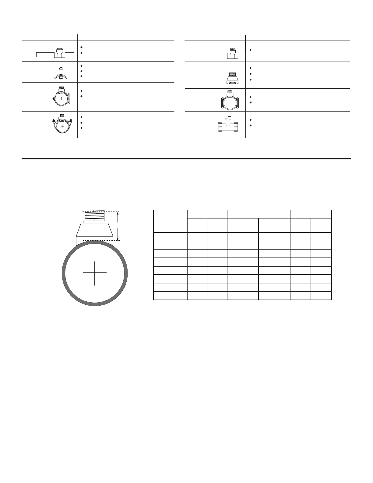
Type Description
Plastic tees
PVC
Glue-on
Saddles
PVC
Saddles
Iron
Strap-on
saddles
0.5 to 4 inch versions
PVC or CPVC
Available in 10 and 12 inch sizes only
Cut 2-1/2 inch hole in pipe
Weld in place using solvent cement
2 to 4 inch, cut 1-7/16 inch hole in pipe
6 to 8 inch, cut 2-1/4 inch hole in pipe
2 to 4 inch, cut 1-7/16 inch hole in pipe
Over 4 inch, cut 2-1/4 inch hole in pipe
Special order over 12 inch
Type
Carbon steel &
stainless steel
threaded tees
Carbon steel &
stainless steel
Weld-on
Weldolets
Metric
PVC-U
Saddle
Metric
Union
Fitting
Description
0.5 to 2 inch versions
2 to 4 inch, cut 1-7/16 inch hole in pipe
Over 4 inch, cut 2-1/4 inch hole in pipe
See section 4 below for details
For pipes DN 65 to 200 mm
Requires a 30 mm diam. hole in the pipe
For pipes from DN 15 to 50 mm
PP or PVDF
Consult the K-Factor section of the OMEGA fl ow sensor instruction manual for a complete listing of installation fi ttings.
5. H-Dimensions
The plastic sensor insert in the Weldolet or Brazolet fi tting MUST be removed before the welding process. When reinstalled, it is
important that the insert be threaded to the proper height ("H" dimension).
"H"
"H" dimension Part Number "H" dimension
Part Number
Carbon Steel
FP-5325CS 2.33 59.18 FMG-5325 FP-5325BR 2.33 59.18
FP-5330CS 2.32 58.92 FMG-5330 FP-5330BR 2.32 58.92
FP-5340CS 2.30 58.42 FMG-5340 FP-5340BR 2.30 58.42
FP-5350CS 3.09 78.48 FMG-5350 FP-5350BR 3.09 78.48
FP-5360CS 2.96 75.18 FMG-5360 FP-5360BR 2.96 75.18
FP-5380CS 2.73 69.34 FMG-5380 FP-5380BR 2.73 69.34
FP-5381CS 5.48 139.19 FMG-5381 FP-5381BR 5.48 139.19
FP-5382CS 5.25 133.35 FMG-5382 FP-5382BR 5.25 133.35
inches mm
Stainless
Steel
Copper/
Bronze inches mm
3Omega FP-319 Flow Wet-Tap Assembly
Page 6

6. Ordering Information
Part Number Description
FP-319 PVC wet-tap valve (sensor not included)
FMK-515-3P3 Polypro extended length paddlewheel sensor (0.5 to 4 in.)
FMK-515-3P5 Polypro extended length paddlewheel sensor (10 to 36 in.)
FMK-2536-3P3 Polypro extended length low fl ow paddlewheel sensor (0.5 to 4 in.)
4 Omega FP-319 Flow Wet-Tap Assembly
Page 7

WARRANTY/DISCLAIMER
OMEGA ENGINEERING, INC. warrants this unit to be free of defects in materials and workmanship for a
period of 13 months from date of purchase. OMEGA’s WARRANTY adds an additional one (1) month
grace period to the normal one (1) year product warranty to cover handling and shipping time. This
ensures that OMEGA’s customers receive maximum coverage on each product.
If the unit malfunctions, it must be returned to the factory for evaluation. OMEGA’s Customer Service
Department will issue an Authorized Return (AR) number immediately upon phone or written request.
Upon examination by OMEGA, if the unit is found to be defective, it will be repaired or replaced at no
charge. OMEGA’s WARRANTY does not apply to defects resulting from any action of the purchaser,
including but not limited to mishandling, improper interfacing, operation outside of design limits,
improper repair, or unauthorized modification. This WARRANTY is VOID if the unit shows evidence of
having been tampered with or shows evidence of having been damaged as a result of excessive corrosion;
or current, heat, moisture or vibration; improper specification; misapplication; misuse or other operating
conditions outside of OMEGA’s control. Components in which wear is not warranted, include but are not
limited to contact points, fuses, and triacs.
OMEGA is pleased to offer suggestions on the use of its various products. However,
OMEGA neither assumes responsibility for any omissions or errors nor assumes liability for
any damages that result from the use of its products in accordance with information provided
by OMEGA, either verbal or written. OMEGA warrants only that the parts manufactured by the
company will be as specified and free of defects. OMEGA MAKES NO OTHER WARRANTIES OR
REPRESENTATIONS OF ANY KIND WHATSOEVER, EXPRESSED OR IMPLIED, EXCEPT THAT OF
TITLE, AND ALL IMPLIED WARRANTIES INCLUDING ANY WARRANTY OF MERCHANTABILITY
AND FITNESS FOR A PARTICULAR PURPOSE ARE HEREBY DISCLAIMED. LIMITATION OF
LIABILITY: The remedies of purchaser set forth herein are exclusive, and the total liability of
OMEGA with respect to this order, whether based on contract, warranty, negligence,
indemnification, strict liability or otherwise, shall not exceed the purchase price of the
component upon which liability is based. In no event shall OMEGA be liable for
consequential, incidental or special damages.
CONDITIONS: Equipment sold by OMEGA is not intended to be used, nor shall it be used: (1) as a “Basic
Component” under 10 CFR 21 (NRC), used in or with any nuclear installation or activity; or (2) in medical
applications or used on humans. Should any Product(s) be used in or with any nuclear installation or
activity, medical application, used on humans, or misused in any way, OMEGA assumes no responsibility
as set forth in our basic WARRANTY/DISCLAIMER language, and, additionally, purchaser will indemnify
OMEGA and hold OMEGA harmless from any liability or damage whatsoever arising out of the use of the
Product(s) in such a manner.
RETURN REQUESTS/INQUIRIES
Direct all warranty and repair requests/inquiries to the OMEGA Customer Service Department.
BEFORE RETURNING ANY PRODUCT(S) TO OMEGA, PURCHASER MUST OBTAIN AN AUTHORIZED
RETURN (AR) NUMBER FROM OMEGA’S CUSTOMER SERVICE DEPARTMENT (IN ORDER TO AVOID
PROCESSING DELAYS). The assigned AR number should then be marked on the outside of the return
package and on any correspondence.
The purchaser is responsible for shipping charges, freight, insurance and proper packaging to prevent
breakage in transit.
FOR WARRANTY RETURNS, please have the
following information available BEFORE contacting
OMEGA:
1. Purchase Order number under which the product
was PURCHASED,
2. Model and serial number of the product under
warranty, and
3. Repair instructions and/or specific problems
relative to the product.
OMEGA’s policy is to make running changes, not model changes, whenever an improvement is possible. This affords
our customers the latest in technology and engineering.
OMEGA is a registered trademark of OMEGA ENGINEERING, INC.
© Copyright 2016 OMEGA ENGINEERING, INC. All rights reserved. This document may not be copied, photocopied,
reproduced, translated, or reduced to any electronic medium or machine-readable form, in whole or in part, without the
prior written consent of OMEGA ENGINEERING, INC.
FOR NON-WARRANTY REPAIRS,
OMEGA for current repair charges. Have
the following information available BEFORE
contacting OMEGA:
1. Purchase Order number to cover the COST
of the repair,
2. Model and serial number of the product, and
3. Repair instructions and/or specific problems
relative to the product.
consult
Page 8

Where Do I Find Everything I Need for
Process Measurement and Control?
OMEGA…Of Course!
Shop online at omega.com
TEMPERATURE
Thermocouple, RTD & Thermistor Probes, Connectors, Panels & Assemblies
Wire: Thermocouple, RTD & Thermistor
Calibrators & Ice Point References
Recorders, Controllers & Process Monitors
Infrared Pyrometers
PRESSURE, STRAIN AND FORCE
Transducers & Strain Gages
Load Cells & Pressure Gages
Displacement Transducers
Instrumentation & Accessories
FLOW/LEVEL
Rotameters, Gas Mass Flowmeters & Flow Computers
Air Velocity Indicators
Turbine/Paddlewheel Systems
Totalizers & Batch Controllers
SM
pH/CONDUCTIVITY
pH Electrodes, Testers & Accessories
Benchtop/Laboratory Meters
Controllers, Calibrators, Simulators & Pumps
Industrial pH & Conductivity Equipment
DATA ACQUISITION
Communications-Based Acquisition Systems
Data Logging Systems
Wireless Sensors, Transmitters, & Receivers
Signal Conditioners
Data Acquisition Software
HEATERS
Heating Cable
Cartridge & Strip Heaters
Immersion & Band Heaters
Flexible Heaters
Laboratory Heaters
ENVIRONMENTAL
MONITORING AND CONTROL
Metering & Control Instrumentation
Refractometers
Pumps & Tubing
Air, Soil & Water Monitors
Industrial Water & Wastewater Treatment
pH, Conductivity & Dissolved Oxygen Instruments
M3815/0916
 Loading...