

Page 1
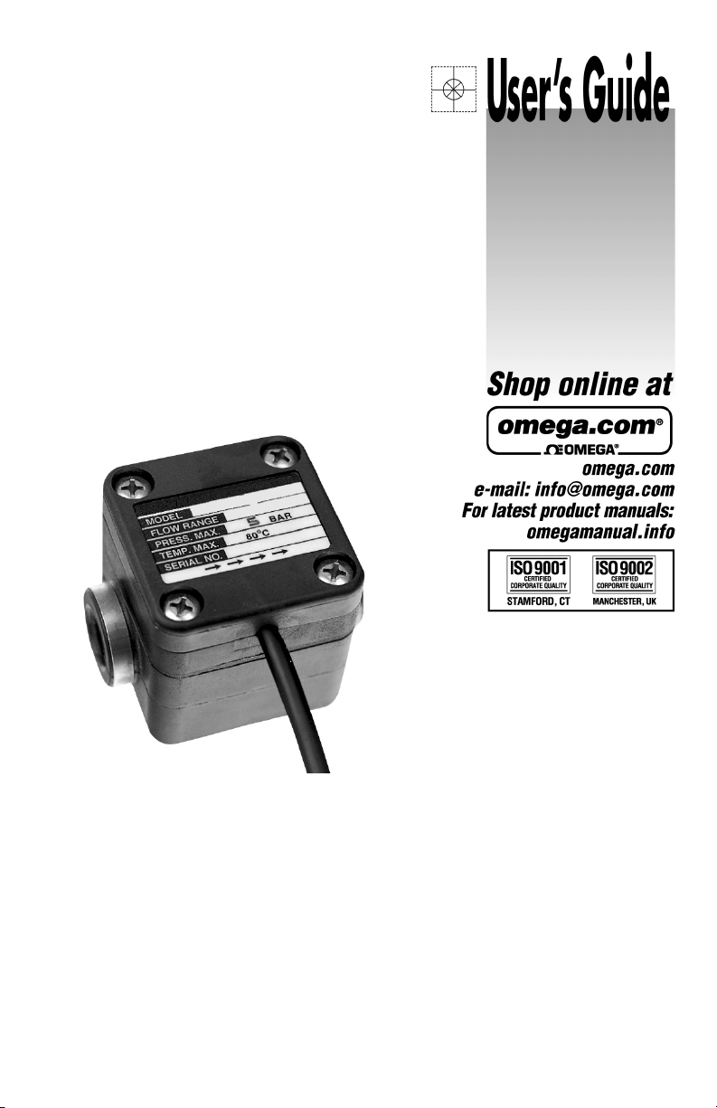
FPD1001B thru FPD1003B,
FPD1102B and FPD1103B,
FPD1201B thru FPD1203B
SERIES LOW FLOW
Positive Displacement Flowmeters
Page 2

Page 3

To the owner:
Please take a few minutes to read through
the manual before installing and operating
your meter. Always retain this manual for
future reference. If you have any problems
with the meter, refer to the Maintenance and
Troubleshooting sections of the manual.
This manual contains connection and operating instructions for the OMEGA FPD
Series meters. This includes the following
models:
FPD1001B FPD1102B
FPD1201B FPD1003B
FPD1002B FPD1203B
FPD1202B FPD1103B
Part breakdowns for each model are located at the back of this manual. For models
with displays and /or 4-20 mA output, an
additional instruction manual is provided.
The flowmeter has incorporated the oval rotor principal into its design. This has proven
to be a reliable and highly accurate method
of measuring flow. Exceptional repeatability
and high accuracy over a wide range of
fluid viscosities and flowrates are features
of the oval rotor design. With low pressure
drop and high pressure rating, oval rotor
flowmeters are suitable for both gravity and
pump (in-line) applications.
OPERATION
Please read this information
!
▲
carefully before use!
Before use, confirm the fluid to be used is
compatible with the meter. Refer to Industry
fluid compatibility charts or consult your
local representative for advice.
To prevent damage from dirt or foreign
matter it is recommended that a Y or basket type 200 mesh strainer be installed as
close as possible to the inlet side of the
meter. Contact your local representative
for advice.
NOTE: To prevent damage to the meter,
slowly fill the system with fluid (this will
prevent damage caused by air purge).
Failure to do this could damage the
meter.
To reduce pressure build up, turn off the
pump at the end of each day.
INSTALLATION
1. Use thread sealant on all pipe threads.
2. Ensure the meter is installed so that
rotor shafts are always in a horizontal
plane. Flow is bi-directional.
3. OMEGA recommends use of flexible
connections.
4. Extreme care must be taken when
installing the meter. Pipe strain or
overtightening the meter connections
can cause meter damage.
PULSER DETAILS
Your meter is equipped with both a Hall
Effect sensor and a Reed Switch sensor.
The equipment you are sending the pulse
signal to will determine which sensor you
use. The wires for the unused sensor will
not be used.
Refer to page 2 for specifications and wiring connections.
1
Page 4
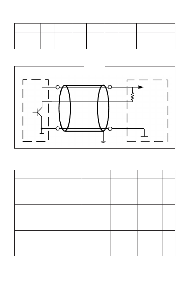
Sensor Wiring Connections
Output Type Wire Function Wire Function Wire Function Note
Reed Switch Green Yellow No Polarity Required
Hall Effect Red +VDC Black Gnd (0 V) White Signal NPN Open Collector
Figure 1
Typical NPN Open Collector
+
VDC
SIG
Signal
Power Supply
1.8k Ω 24 VDC
Value depends on
voltage. Check if
receiving instrument
has internal Pull Up
resistor.
0 VDC
Hall Effect
GND
Receiving Instrument
Hall Effect Specifications (Absolute Maximum Ratings)
Characteristic Symbol Notes Rating Units
Voltage Supply VCC 30 V
Reverse Supply Voltage V
Output Off Voltage V
Reverse Output Voltage V
Output Current I
Magnetic Flux Density B Unlimited G
Operating Ambient Temperature TA Range L -40 to 150 ° C
Maximum Junction Temperature T
Storage Temperature T
-30 V
RCC
30 V
OUT
-0.5 V
ROUT
25 mA
OUTSNK
(MAX) 165 ° C
J
STG
-65 to 170 ° C
2
Page 5
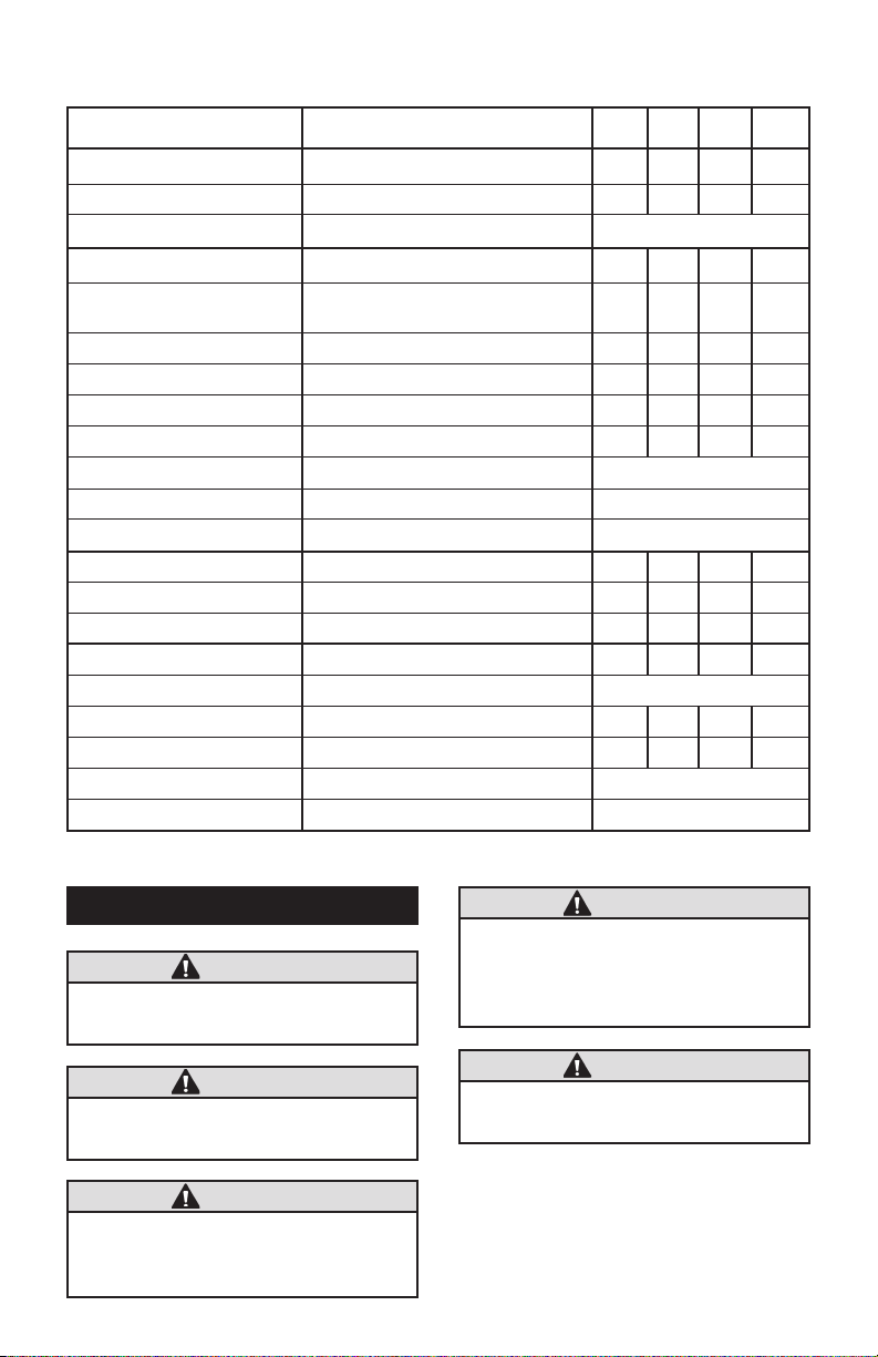
Reed Switch Specifications
Conditions Min. Typ. Max. Unit
Magnetic Properties:
Pull-In at 20°C 36.5 AT
Test Equipment KMS-03
Special Product Data:
Contact Rating Any DC combination of V & A not
to exceed their individual max.’s 10 W
Switching Voltage DC or Peak AC 30 VDC
Operating Ampere DC or Peak AC 0.5 A
Switching Current DC or Peak AC 0.5 A
Sensor Resistance Measured with 40% overdrive 360 mOhm
Housing Material Celanex 3216
Case Color Black
Sealing Compound Epoxy Resin
Environmental Data:
Operating Temperature -5 130 °C
Storage Temperature -20 130 °C
Cable Specifications:
Cable Type Single Wires
Temp. Range Unmoved -30 130 °C
Temp. Range Moved -5 130 °C
Cable Material FEP
Cross Section AWG 28
MAINTENANCE
CAUTION
Ensure the fluid is isolated from the
meter to be repaired.
CAUTION
Ensure the fluid line is depressurized
before commencing repairs.
CAUTION
Ensure electrical wiring is isolated
and disconnected before commencing repairs.
CAUTION
To prevent damage to the meter during re-commissioning, slowly fill the
piping system with fluid before starting the pumping system.
CAUTION
Refer to the Sensor Wiring section for
details.
3
Page 6
Body
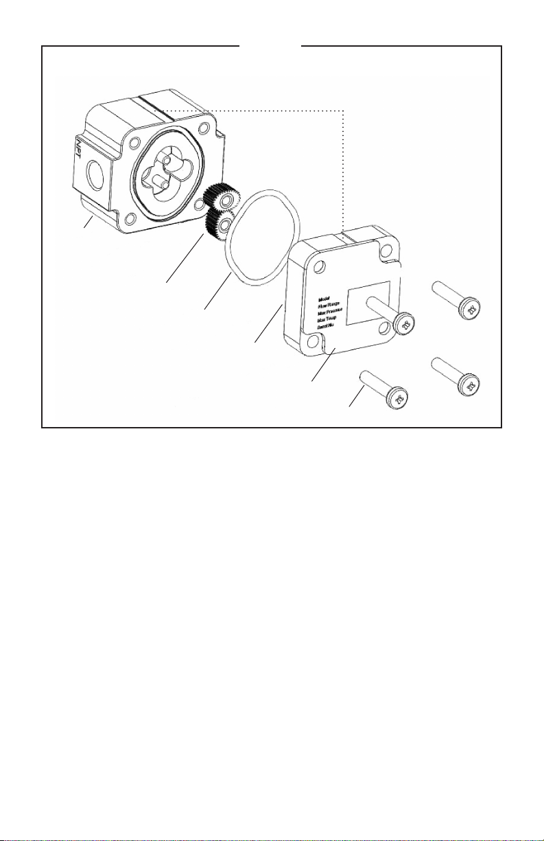
Figure 2
Pulse Meter Parts Breakdown
Allignment
Marks
Rotors
O-Ring
Meter Cap
Legend Plate
Screws
Pulse Meter Disassembly
1. Loosen and remove four Phillips head
or cap head screws (see Figure 2).
2. Remove the meter cap and O-ring.
3. Remove the rotors. Note the position
of the rotor with the magnet or grub
screws.
4. Clean and inspect all components,
replace as necessary.
Pulse Meter Reassembly
1. Replace the rotors. Refer to Figure 3 or
Figure 4 for correct orientation. Rotate
the rotors by hand to ensure correct
engagement.
2. Fit the O-ring into the O-ring groove in
the meter body.
4
3. Replace the meter cap.
NOTE: Ensure all the alignment marks are
lined up with the mark on the body
(see Figure 2).
4. Replace and tighten the four bolts
to the required torque. Refer to Bolt
Torque in the Specifications section
for details.
5. Check meter function using low air
pressure.
6. Restore the fluid and reconnect the
wiring as detailed in the Installation and
Pulser Details sections.
Page 7
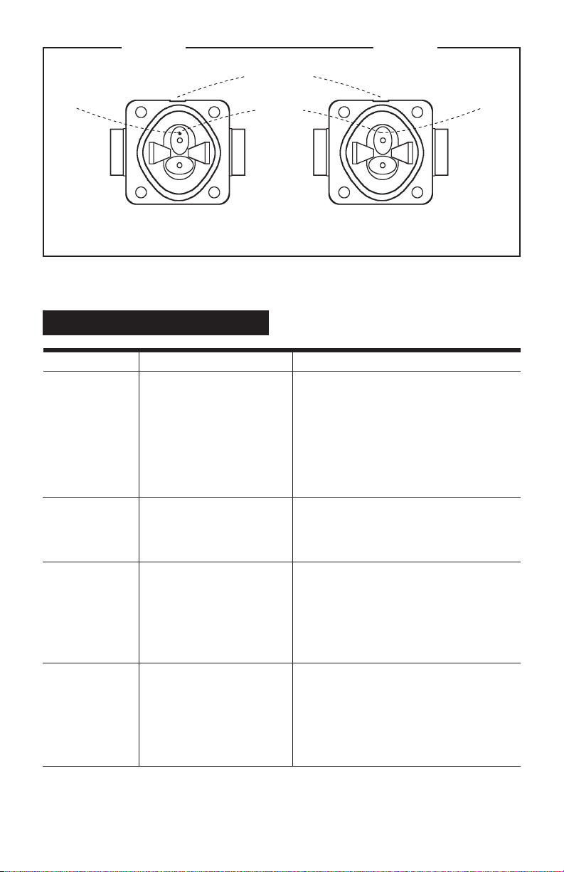
Magnets
Visible
Figure 3 Figure 4
Alignment Marks
Rotors with
Magnets
Magnets
NOT Visible
Models: FPD1001B & FPD1201B Models: FPD1002B, FPD1003B, FPD1102B,
FPD1103B, FPD1202B & FPD1203B
TROUBLESHOOTING
Symptom Probable Cause Corrective Action
FLUID WILL NOT 1. Foreign matter blocking Dismantle meter, clean rotors. Strainer must
FLOW THROUGH rotors be fitted in-line.
THE METER
2. Line strainer blocked Clean strainer.
3. Damaged rotors Replace rotors. Strainer must be fitted in-line.
4. Meter connections over- Readjust connections.
tightened
REDUCED FLOW 1. Line strainer partially Clean strainer.
THROUGH THE blocked
METER
2. Fluid is too viscous Maximum viscosity 1000 centipoise.
METER READING 1. Fluid flowrate is too low See specifications for minimum and maximum
INACCURATE or too high flowrates.
2. Air in fluid Bleed air from system.
3. Excess wear caused by Check meter body and rotors.
incorrect installation
METER NOT 1. Faulty Hall Effect sensor Replace meter cap.
GIVING A PULSE or Reed Switch
SIGNAL
2. Faulty magnet Replace rotors.
3. Rotors installed in wrong Refer to correct rotor positioning and
position assembly instructions.
5
Page 8

WETTED MATERIALS
Component Wetted Materials
Body:
FPD1001B, FPD1002B & FPD1003B Aluminum
FPD1102B & FPD1103B PPS
FPD1201B, FPD1202B & FPD1203B 316L Stainless Steel
Shafts:
FPD1001B, FPD1002B, FPD1003B, 316 Stainless Steel
FPD1201B, FPD1202B & FPD1203B
FPD1102B & FPD1103B Hastalloy (optional)
Rotors:
FPD1001B, FPD1002B, FPD1003B, PM Stainless Steel
FPD1201B, FPD1202B & FPD1203B
FPD1102B & FPD1103B PPS
Bushings:
FPD1001B, FPD1201B, FPD1002B, Carbon
FTB1003B, FPD1102B, FPD1103B,
FPD1202B & FPD1203B
Inner Plate / Meter Cap:
FPD1001B, FPD1002B, FPD1003B, PPS
FPD1102B & FPD1103B
FPD1201B, FPD1202B & FPD1203B Stainless Steel
Magnet:
All models Samarium Cobalt
6
Page 9
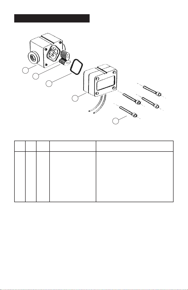
DISPLAY PARTS LISTING
Models: FPD1001B
FPD1201B
1
4
5
2
3
u = Recommended Spare Parts (See Figure 2).
Bold Text = Indicates Stainless Steel model parts.
Item Rec. Part or Set
No. Qty. Parts (Order from this column only) Part Description
1 1 MS600NS Meter Body & Shafts NPT Stainless Steel
1 1 MS605NS Meter Body & Shafts NPT Aluminum
2 1 u MS1180AS Meter Cap (FPD1001B)
2 1 u MS1180-1AS Meter Cap (FPD1201B)
3 4 MS1228S Screws, Aluminum
3 4 MS12138 Screws, Stainless Steel
4 1 MS601S Rotor Assembly Stainless Steel
5 1 BS029VS O-Ring (FKM)
5 1 BS029PS O-Ring (Perfluoroelastomer)
7
Page 10

SPECIFICATIONS
Stainless Steel Models Aluminum Models
Port Size 1/8 in. 1/8 in.
Accuracy of Reading ± 1% ± 1%
Maximum Viscosity 1000 Centipoise 1000 Centipoise
Flow Ranges (LPH or GPH)
Above 5 centipoise 0.5 to 50 / 0.132 to 13.2 0.5 to 50 / 0.132 to 13.2
Below 5 centipoise 2 to 50 / 0.528 to 13.2 2 to 50 / 0.528 to 13.2
K-Factor (Pulses per Liter/Gallon) 1552 / 5875.32 1552 / 5874.32
Max. Operating Pressure SS = 5500 kPa / 800 PSI / 55 Bar 1000 kPa / 150 PSI / 10 Bar
Strainer Size (Recommended) 200 Mesh 200 Mesh
Bolt Torque SS = 80 in-lb. 17.7 in-lb.
Min. Operating Temperature -10°C / +14°F -10°C / +14°F
Max. Operating Temperature 120°C / 248°F 60°C / 176°F
Pulse Type Hall Effect Sensor/Reed Switch Hall Effect Sensor/Reed Switch
Cable Length 1 meter / 3.28 feet 1 meter / 3.28 feet
Weight 602 g / 21.23 oz. 308 g / 10.86 oz.
Dimensions (W x D x H) 60mm x 50mm x 50mm 60mm x 50mm x 50mm
Face to Face 67mm / 2.63 in. 60mm / 2.36 in.
8
Page 11
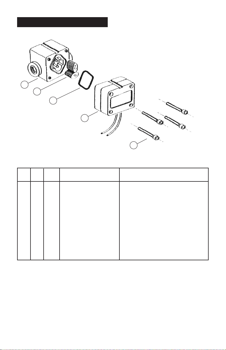
DISPLAY PARTS LISTING
Models: FPD1002B
FPD1202B
FPD1102B
1
2
5
4
3
u = Recommended Spare Parts (See Figure 2).
Bold Text = Indicates Stainless Steel model parts.
Item Rec. Part or Set
No. Qty. Parts (Order from this column only) Part Description
1 1 MS1S-2S Meter Body & Shafts NPT Stainless Steel
1 1 MS1AL-2S Meter Body & Shafts NPT Aluminum
1 1 MS1R-2C Meter Body & Hast Shafts NPT PPS
2 1 MS6-1S Rotor Assembly Stainless Steel
2 1 MS6S Rotor Assembly PPS
3 4 MS1228S Screws, Aluminum/PPS
3 4 MS1213S Screws, Stainless Steel
4 1 u MS1180AS Meter Cap (FPD1002B)
4 1 u MS1180-1AS Meter Cap (FPD1202B)
4 1 u MS11870RAS Meter Cap (FPD1102B)
5 1 BS029VS O-Ring (FKM)
5 1 BS029PS O-Ring (Perfluoroelastomer)
9
Page 12

SPECIFICATIONS
Stainless Steel & PPS Models Aluminum Models
Port Size 1/4 in. 1/4 in.
Accuracy of Reading ± 1% ± 1%
Maximum Viscosity 1000 Centipoise 1000 Centipoise
Flow Ranges (LPH or GPH)
Above 5 centipoise 2 to 100 / 0.53 to 26.4 2 to 100 / 0.53 to 26.4
Below 5 centipoise 5 to 100 / 1.32 to 26.4 5 to 100 / 1.32 to 26.4
K-Factor (Pulses per Liter/Gallon) 1000 / 3785 1000 / 3785
Max. Operating Pressure SS = 5515 kPa /800 PSI / 55 Bar 1000 kPa/ 150 PSI / 10 Bar
PPS = 500 kPa / 75 PSI / 5 Bar
Strainer Size (Recommended) 200 Mesh 200 Mesh
Bolt Torque SS = 80 in-lb. 17.7 in-lb.
PPS = 8.8 in-lb.
Min. Operating Temperature -10°C / +14°F -10°C / +14°F
Max. Operating Temperature SS = 120°C / 248°F 80°C / 176°F
PPS = 80°C / 176°F
Pulse Type Hall Effect Sensor/Reed Switch Hall Effect Sensor/Reed Switch
Cable Length 1 meter / 3.28 feet 1 meter / 3.28 feet
Weight SS = 240 g / 8.5 oz. 310 g / 11 oz.
PPS = 600 g / 21.2 oz.
Dimensions (W x D x H) 60mm x 50mm x 50mm 60mm x 50mm x 50mm
Face to Face SS = 67mm / 2.63 in. 60mm / 2.36 in.
PPS = 64mm / 2.52 in.
10
Page 13
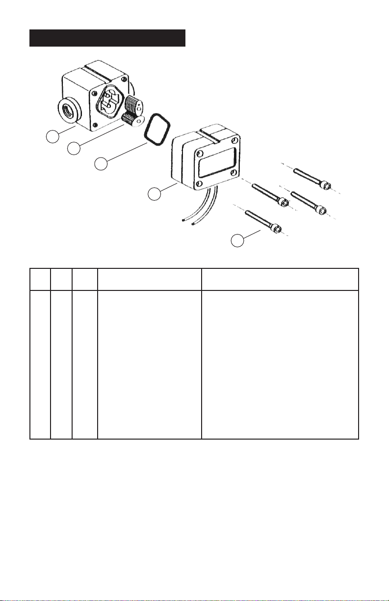
DISPLAY PARTS LISTING
1
4
5
2
Models: FPD1003B
FPD1203B
FPD1103B
u = Recommended Spare Parts (See Figure 2).
Bold Text = Indicates Stainless Steel model parts.
Item Rec. Part or Set
No. Qty. Parts (Order from this column only) Part Description
1 1 MS2S-2S Meter Body & Shafts NPT Stainless Steel
1 1 MS2AL-2S Meter Body & Shafts NPT Aluminum
1 1 MS2R-2C Meter Body & Hast Shafts NPT PPS
2 1 u MS1180AS Meter Cap (FPD1003B)
2 1 u MS1180-1AS Meter Cap (FPD1203B)
2 1 u MS1180RAS Meter Cap (FPD1103B)
3 4 MS1228S Screws, Aluminum
3 4 MS1213S Screws, Stainless Steel
4 1 MS814S Rotor Assembly Stainless Steel
4 1 MS813S Rotor Assembly PPS
4 1 MS814HS Rotor Assembly Stainless Steel High Viscosity
5 1 BS029VS O-Ring (FKM)
5 1 BS029PS O-Ring (Perfluoroelastomer)
3
11
Page 14

SPECIFICATIONS
Stainless Steel & PPS Models Aluminum Models
Port Size 1/4 in. 1/4 in.
Accuracy of Reading ± 1% ± 1%
Max. Viscosity 1000 Centipoise 1000 Centipoise
High Viscosity Option Yes Yes
Flow Ranges (LPH or GPH)
Above 5 centipoise 15 to 500 / 4 to 32 15 to 500 / 4 t o 32
Below 5 centipoise 25 to 500 / 6 to 132 25 to 500 / 6 to 132
K-Factor (Pulses per Liter/Gallon) 400 / 1514 400 / 1514
Max. Operating Pressure SS = 5515 kPa/800 PSI/55 Bar 1000 kPa/150 PSI/10 Bar
PPS = 500 kPa/75 PSI/5 Bar
Strainer Size (Recommended) 200 Mesh 200 Mesh
Bolt Torque SS = 80 in-lb. 17.7 in./lbs.
PPS = 8.8 in-lb.
Min. Operating Temperature -10°C / +14°F -10°C / +14°F
Max. Operating Temperature SS = 120°C / 248°F 80°C / 176°F
PPS = 80°C / 176°F
Pulse Type Hall Effect Sensor/Reed Switch Hall Effect Sensor/Reed Switch
Cable Length 1 meter / 3.28 feet 1 meter / 3.28 feet
Weight 240 g / 8.5 oz. 320 g / 12 oz.
600 g / 21.2 oz. (PPS)
Dimensions (W x D x H) 60mm x 50mm x 50mm 60mm x 50mm x 50mm
Face to Face SS = 67mm / 2.63 in. 60mm / 2.36 in.
PPS = 64mm / 2.52 in.
12
Page 15

Page 16

M-4 686 / 0611
 Loading...