

Page 1
Page 2
Page 3

1
FOH201
User manual
Page 4
2
WARNINGS
WARNING: HIGH PRESSURE!
High pressure gases and liquids are potentially hazardous. Energy
stored in these gases or liquids can be released suddenly and with
extreme force. High pressure systems should be assembled and
operated only by personnel who have been trained in proper safety
practices.
WARNING : HIGH STRAIN!
Highly strained materials and parts are potentially hazardous. Energy
stored in these materials or parts can be released suddenly and with
extreme force. Highly strained systems should be assembled and
operated only by personnel who have been trained in proper safety
practices.
WARNING: NOT EXPLOSION PROOF!
Installation of this instrument in an area requiring devices rated as
intrinsically safe is not recommended.
WARNING: VOLTAGE SUPPLY!
Use only the wall plug-in power supply delivered with your instrument
and verifies that the input voltage and frequency are compatible with the
power outlet.
Page 5

3
TABLE OF CONTENT
1. Quick start 5
1.1 FOH201 Powering 5
1.2 Sensor Connection 6
1.3 FOH201 setup 6
1.4 Define a sensor 7
1.5 Select a sensor among previously defined sensors 7
1.6 Zeroing a sensor (when required) 8
2. Operating Principle 8
3. Sensor type 8
4. Local Operation 9
4.1 Keyboard 9
4.1.1 Switch on/off 9
4.1.2 Menu Button 9
4.1.3 Left/Right Arrows 9
4.1.4 Up/Down Arrows 9
4.1.5 Confirmation button 9
4.1.6 Define Button 9
4.1.7 Select Button 10
4.1.8 Null Button 10
4.2 Sensor-related functions 10
4.2.1 Define sensor 10
4.2.2 Select sensor 10
4.2.3 Modify Gauge Factor 11
4.2.4 Delete Defined Sensor 11
4.3 System Setting 11
4.3.1 Average 11
4.3.2 Analog output 11
4.3.3 Auto 12
4.3.4 Unit Mod 12
4.4 System Diagnostic 12
4.5 Calib 13
4.6 Null button 13
4.6.1 Type T1, T2 Temperature sensors 13
4.6.2 Type P2, P3, Pv Pressure sensors; Type S1 strain sensors 13
4.6.3 Type N and X 13
4.7 Defining a sensor (Menu levels) 14
4.8 Selecting a sensor (Menus levels) 15
4.9 Modifying Gauge Factor(s) (Menus levels) 16
4.10 Delete Gauge Factor (Menus levels) 17
4.11 Averaging measurements (Menus levels) 18
Page 6

4
4.12 Setting the analog output (Menus levels) 19
4.13 Unit mode (Menus levels) 20
4.14 Diagnostic (Menus levels) 21
4.15 Zeroing pressure sensor of P2, P3 type; Strain sensor of S1 Type (Menus levels) 22
5. Remote operation 23
6. Specifications 24
Page 7
5
1. Quick start
1.1 FOH201 Powering
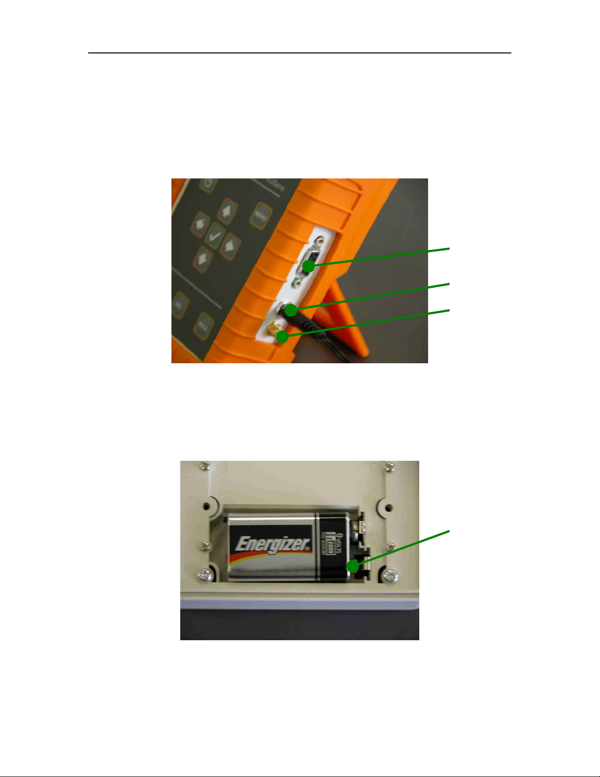
Connect the plug-in wall or tabletop power supply to a power outlet. Verify that the power
supply complies with the voltage and frequency outlet. Connect the power cable to the
PicoSens power connector (Figure 1.1).
Figure 1.1: Electrical connectors
The FOH201 can also be operated from a 9-Volt battery. 9-Volt battery can be replaced
by getting access to the battery compartment as follows: 1) Remove the rubber boot; 2)
remove screws holding the battery panel, 3) install a 9-Volt battery with proper
orientation of the polarity (Figure 1.2).
Figure 1.2: Polarity of 9V battery
Note: Battery operation is not provided for performing continuous measurements
so it should be used for short term field measurements only.
RS-232 Connector
Wall Supply connector
±5V Analog output
Positive pole
6
Page 8
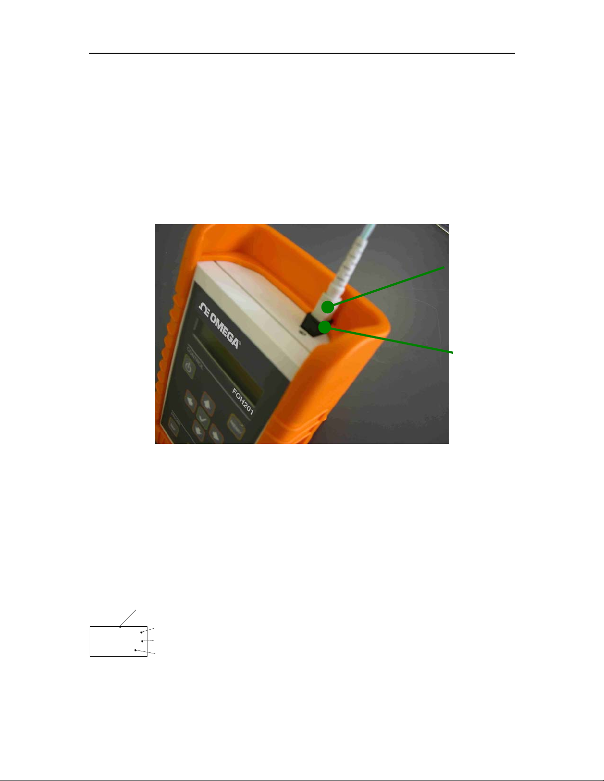
1.2 Sensor Connection
OMEGA fiber-optic sensors or transducers must me mated to the FOH201 output
connector (Figure 2). The optical connector provided with the FOH201 is usually a
square push-pull SC-type connector mounted with a SC-SC type mating. Remove the
protective cap of the mating and engage the sensor connector with the orientation key
properly oriented. It is a good practice to clean the sensor connector prior to connect it to
the signal conditioner.
NOTE: always replace the protective dust cap on the mating when there is no
sensor connected. Always replace the protective dust cap on the sensor fiberoptic connector when not in used
Figure 2: SC mating for connecting the fiber-optic sensor
1.3 FOH201 Setup
The FOH201 is compatible with all OMEGAS’ WLPI type sensors or transducers for
measuring various parameters such as temperature, pressure, strain and displacement.
(To properly use a specific sensor, its corresponding Sensor Type and Gauge Factor(s)
must be entered into the FOH201 non-volatile memory as explained next. These
numbers contain the parameterization factors of the sensor that is the sensor type and
the sensor calibration parameters. These factors are indicated on a label fixed on the
optical cable of the sensor, nearby the optical connector as indicated on the left figure.
The label shows the identification number of the sensor
(used for record purpose only), the Gauge Factors GF0,
GF1, …, and the Sensor Type.
Optical connector
L006-052-02
GF: 225-114
Type:T1
Identification number
Gauge factors: GF0-GF1-...
Sensor type
SENSOR LABEL
Mating
7
Page 9
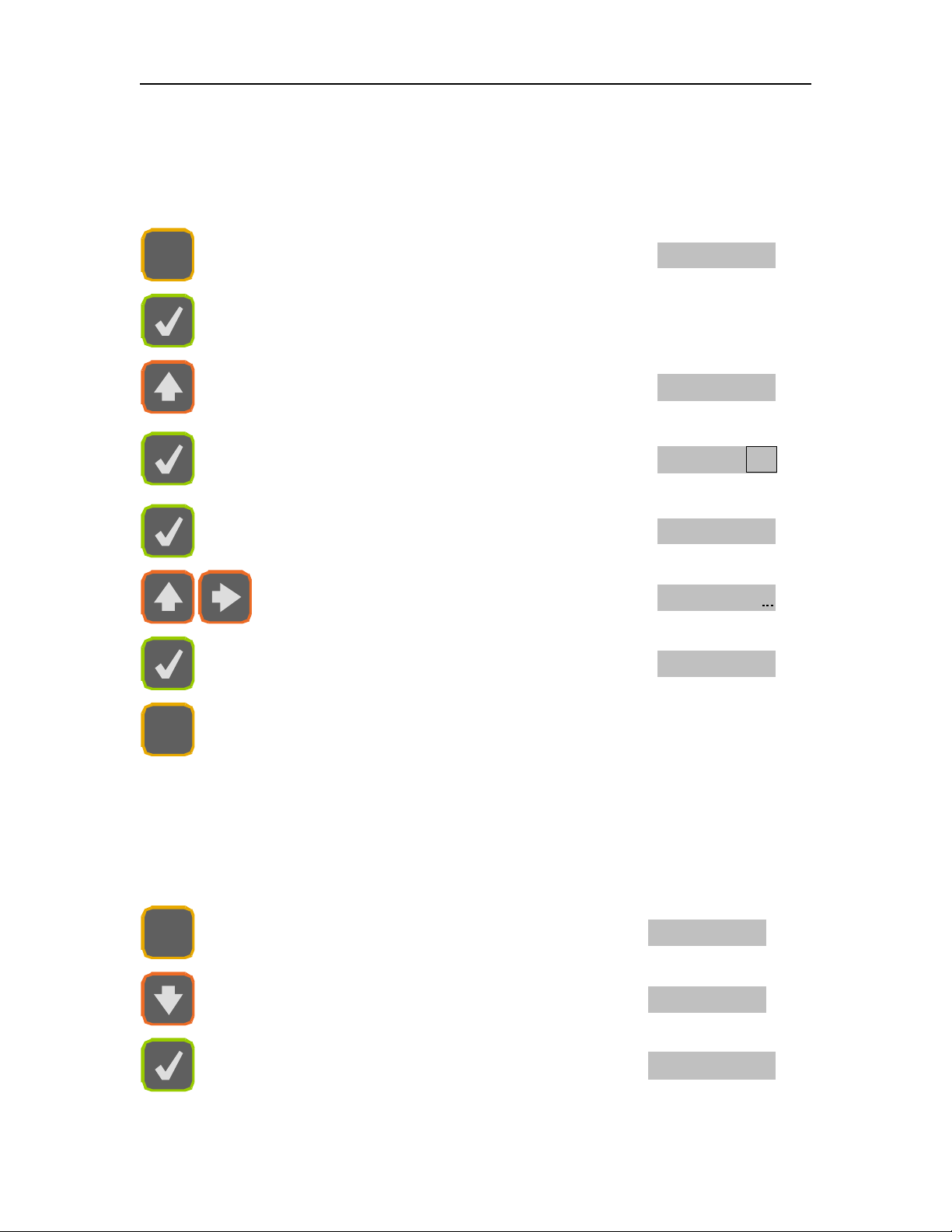
1.4 Define a sensor
Before selecting a specific sensor, it must be defined that is its corresponding Sensor
Type and Gauge Factor must be stored into the non-volatile memory of the PicoSens.
The following example shows how to define a T1 type temperature sensor.
DEF
Enter Define Sensor Menu
Def Pr
Confirm Define Sensor Menu
Select Sensor Type; use up or down arrow
keys
Type T1
Use Default Name or select a name for the
sensor using up or down arrow keys (00 to 99
numbers only)
Pr T102
Default Gauge Factor GF0
GF0 100
Enter Gauge Factor GF0; use arrow keys and
validate the entry with the confirm (√) key
GF0 040
9
Repeat above procedure if other GFs required
GF10300
NULL
Quit the menu
1.5 Select a sensor among previously defined sensors
Once a sensor is defined, it can be selected from the defined sensor list as indicated
below.
SEL
Enter Sensor Select Menu
Sel T201
Select a defined sensor in the list
Sel T202
Confirm selection
36.14°C
Page 10
8
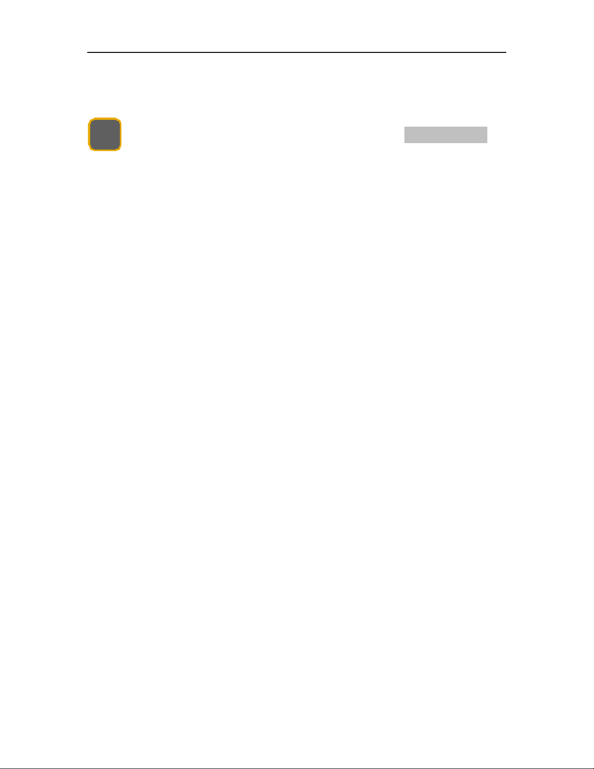
1.6 Zeroing a sensor (when required)
If required, zeroing a sensor is easily done with the NULL button.
NULL
Used with sensors that require zeroing
0.0 psi
2. Operating Principle
The FOH201 is a fiber-optic white light interferometric signal conditioner having the
capability of accurately measuring the absolute path length difference of various type of
sensing interferometers. OMEGA produces a variety of interferometric sensors that are
based on either so-called Fabry-Perot interferometer (low-finesse version) configuration
or the polarization interferometer configuration. For example, OMEGA temperature
sensors are based on a polarization sensing interferometer using the temperaturedependent optical properties of a birefringent crystal while OMEGA pressure, strain and
displacement sensors are based on a Fabry-Perot sensing interferometer where the
distance between the two mirrors of the interferometer varies as a function of the
measured parameter. In all cases, the sensing interferometer is made so its path length
difference varies with the physical parameter of interest. The path length difference of
the sensing interferometer is accurately measured with a nanometer resolution and this
over 30 000 nanometers range.
Physical measurements are possible if the path length difference of the sensing
interferometer is a univocal function of the parameter under scrutiny. This being the
case, the FOH201 must know the relation between the path length difference and the
physical parameter. The Gauge Factors, or equivalently the calibration factors, that
comes with each interferometric sensor contain all the information needed by the
PicoSens to perform the conversion from the measurement of the path length difference
to the physical value being measured.
3. Sensor type
The type of the sensors depends of the physical parameter to be measured. For
example, the T-type (T1, T2, etc) are used for defining temperature sensors, the P-type
(P1, P2, Pv, etc) are used for defining pressure sensors and the S-type are used for
defining strain sensors. There are also special type definitions that are the N-type and
the X-type, which are not related to any specific sensor. These are needed for internal
calibration purpose only and should be not used unless instructions have been given by
OMEGA to do so.
Page 11
9
MENU
DEF
4. Local Operation
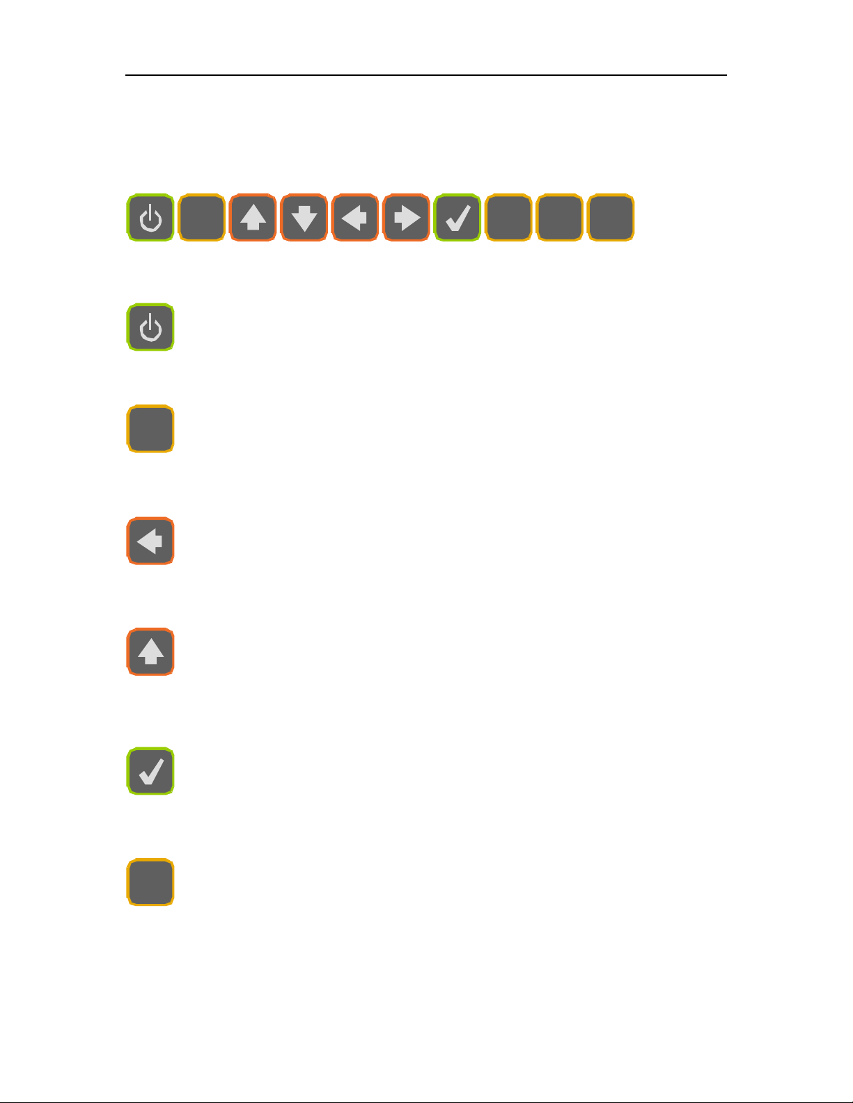
4.1 Keyboard
MENU
DEF
SEL
NULL
4.1.1 Switch on/off
The FOH201 is switched on/off with this button.
4.1.2 Menu Button
Menu button gives access to the system menus. Once in the menu, this button
brings the user one level higher into the menu hierarchy. Once at the root, the
system will exit the menu and goes back to measurement display.
4.1.3 Left/Right Arrows
Left/Right arrows allows navigating 1) within the Gauge Factors of a given
sensor being defined, selected, modified or deleted, or 2) it allows moving from
one digit to the other when a value is being entered.
4.1.4 Up/Down Arrows
Up/Down arrows allows navigating 1) between menu items of a given
hierarchical level, or 2) it allows changing a value being entered.
4.1.5 Confirmation button
Confirmation button permits confirming 1) a new value being entered, 2)
confirm the selection of a menu item then moving one hierarchical level lower,
3) refreshing displayed value in the case of diagnostic.
4.1.6 Define Button
This button is short cut that brings the user directly to the menu item for
defining the Gauge Factor of a new sensor.
Page 12
10
SEL
NULL
4.1.7 Select Button
This button is a short cut that brings the user directly to the menu item for
selecting a new sensor being used.
4.1.8 Null Button
This button allows to cancel most operations taking place, and return directly to
the measurement display. This button is also used for zeroing a sensor when
the system is not within the menu (measurement display mode).
4.2 Sensor-related functions
The functions below are related to the definition of the Sensor type and Gauges Factors
to permit the conversion of the optical measurement into a physical quantity. Those
functions are then related specifically to a given sensor.
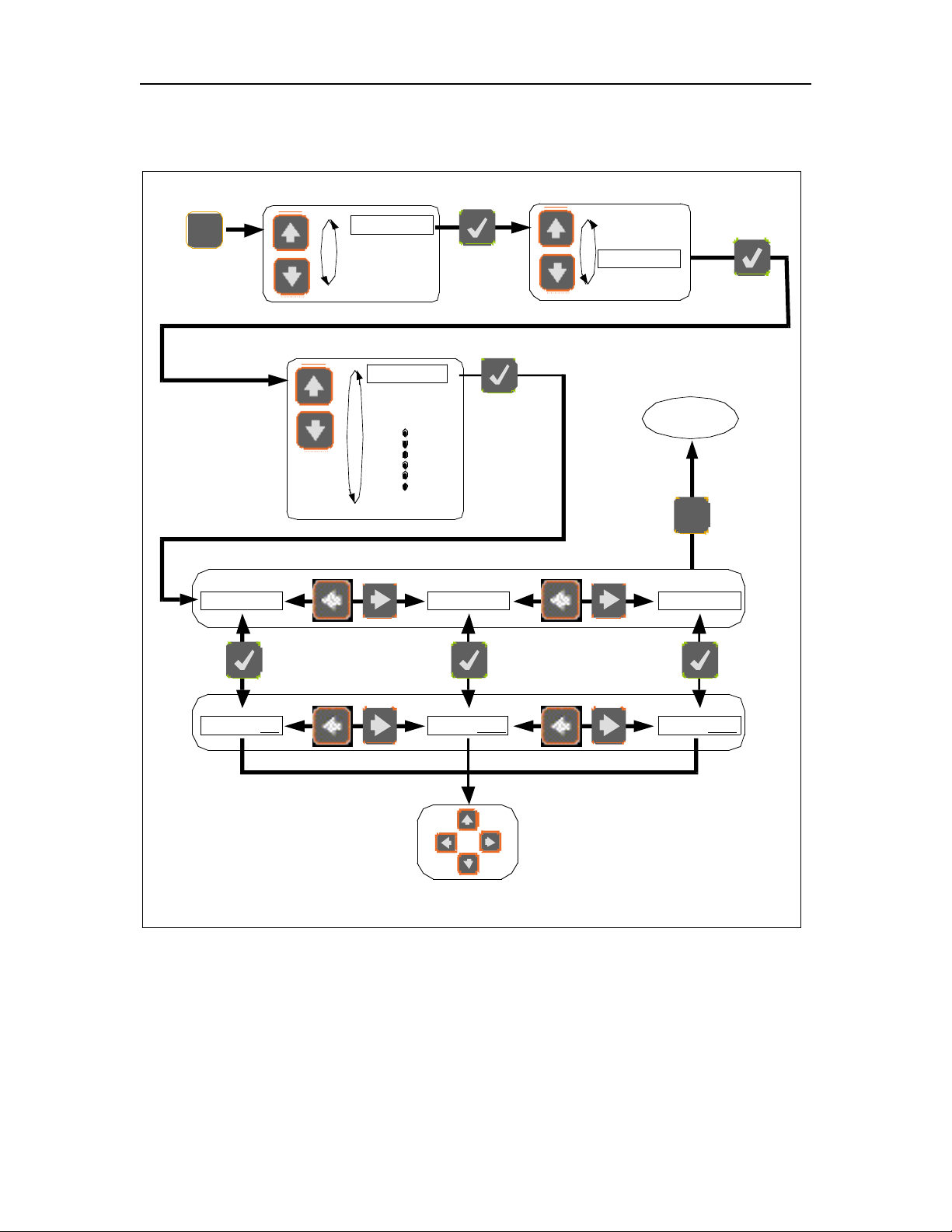
4.2.1 Define sensor
The Sensor Type and Gauge Factors which define a specific sensor must be entered
into the FOH201 for getting a meaningful physical measurement. Methods for defining a
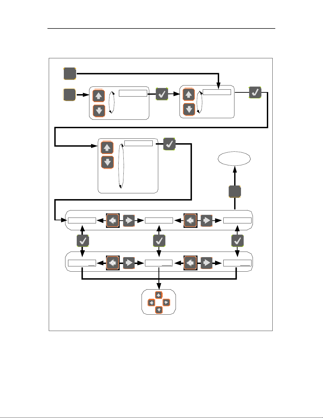
sensor are described in Figure 3. As shown on the figure, one can access to the Define
menu level with the
MENU
button or uses the shortcut
DEF
button. The number of defined
sensors is limited to eight and trying to define an additional sensor will make the
FOH201 to display Mem Full message. The user is first asked to define the type of
sensor being defined, for example Type T1 (see the sensor label for the type to enter).
Once the type is confirmed with button, an allocation for this type of sensor is added
to the sensor list stored in the FOH201 memory. The system then gives a default name
to the sensor, from 01 to 08, e.g. Pr T101. The type of sensor is always part of the
name, while the last two digits can be specified by the user (00 up to 99). Two different
sensors cannot have the same last two digits. If the user tries adding a sensor number
already used, the system will not permit the change and will use the default name. After
confirming the sensor type, the used is requested to enter the Gauge Factor value(s).
Depending of the sensor type, one, two or more GF values must be entered. These
factors are indicated on a label fixed on the optical cable of the sensor, nearby the
optical connector.
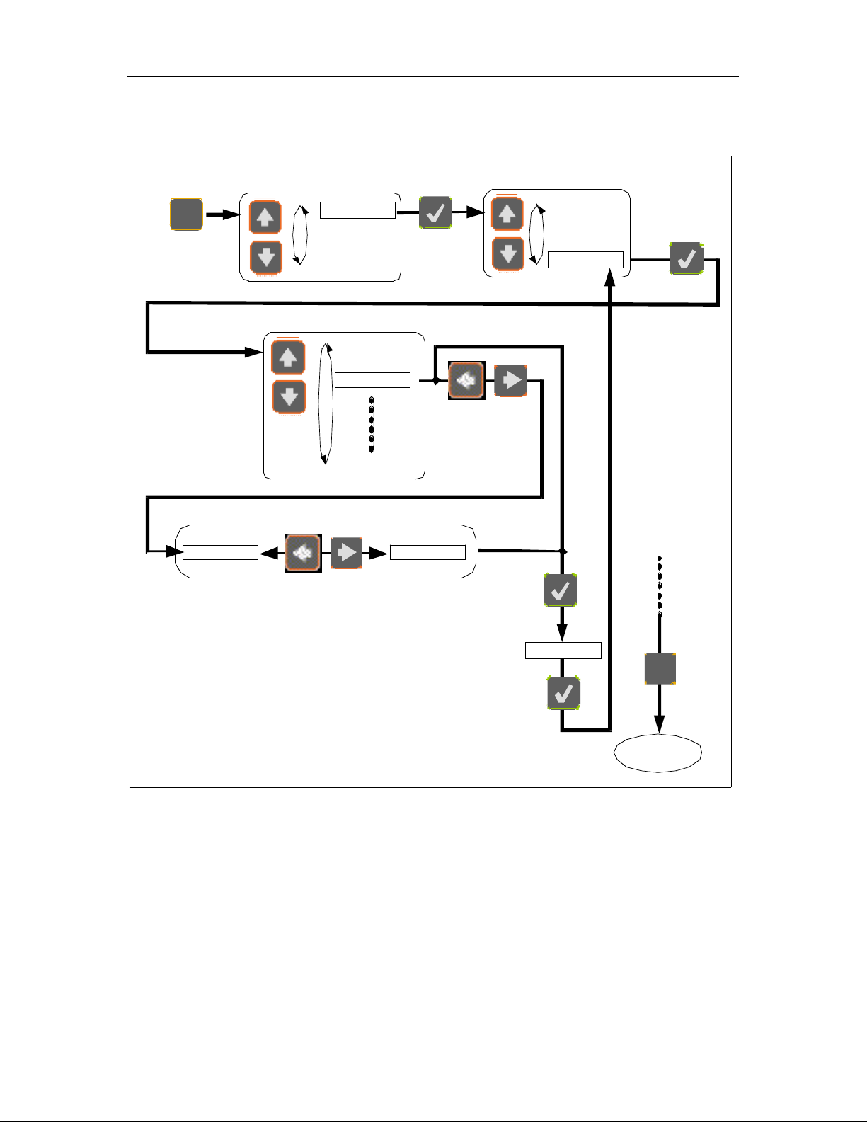
4.2.2 Select sensor
The user must select, within the list of defined sensors (maximum of eight), the specific
sensor connected to the unit. Failure to do so will make the FOH201 to display
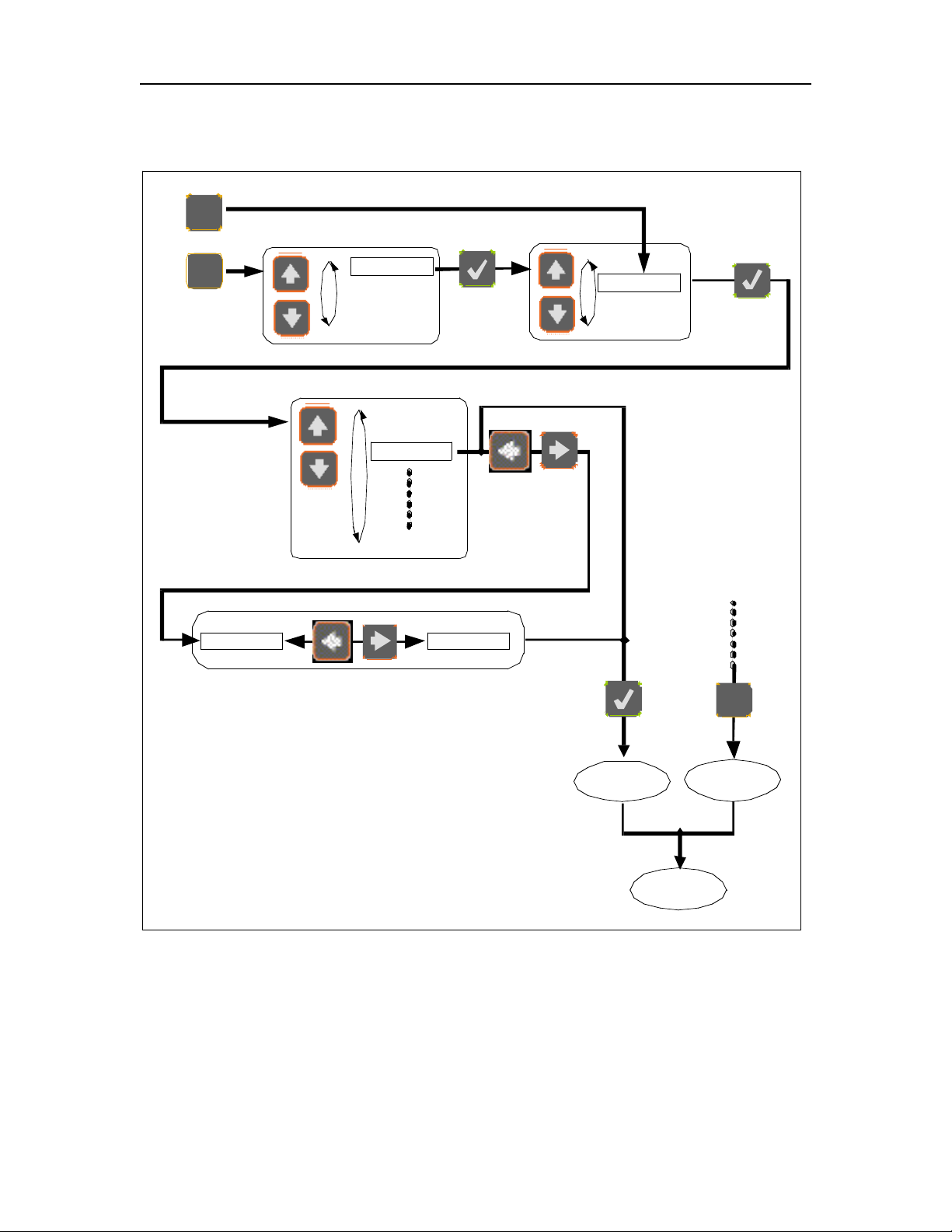
meaningless readings. Methods for selecting the Gauge Factors are described in Figure
4. Once the sensor is selected, a confirmation message is displayed for about 1 second
before it comes back to measurement display.
Page 13

11
4.2.3 Modify Gauge Factor
The user can modify a previously entered Gauge Factor. The method for modifying a
Gauge Factor is described in Figure 5. It is not possible to modify the type of sensor.
The sensor must in this case be deleted, and a new sensor definition must be made.
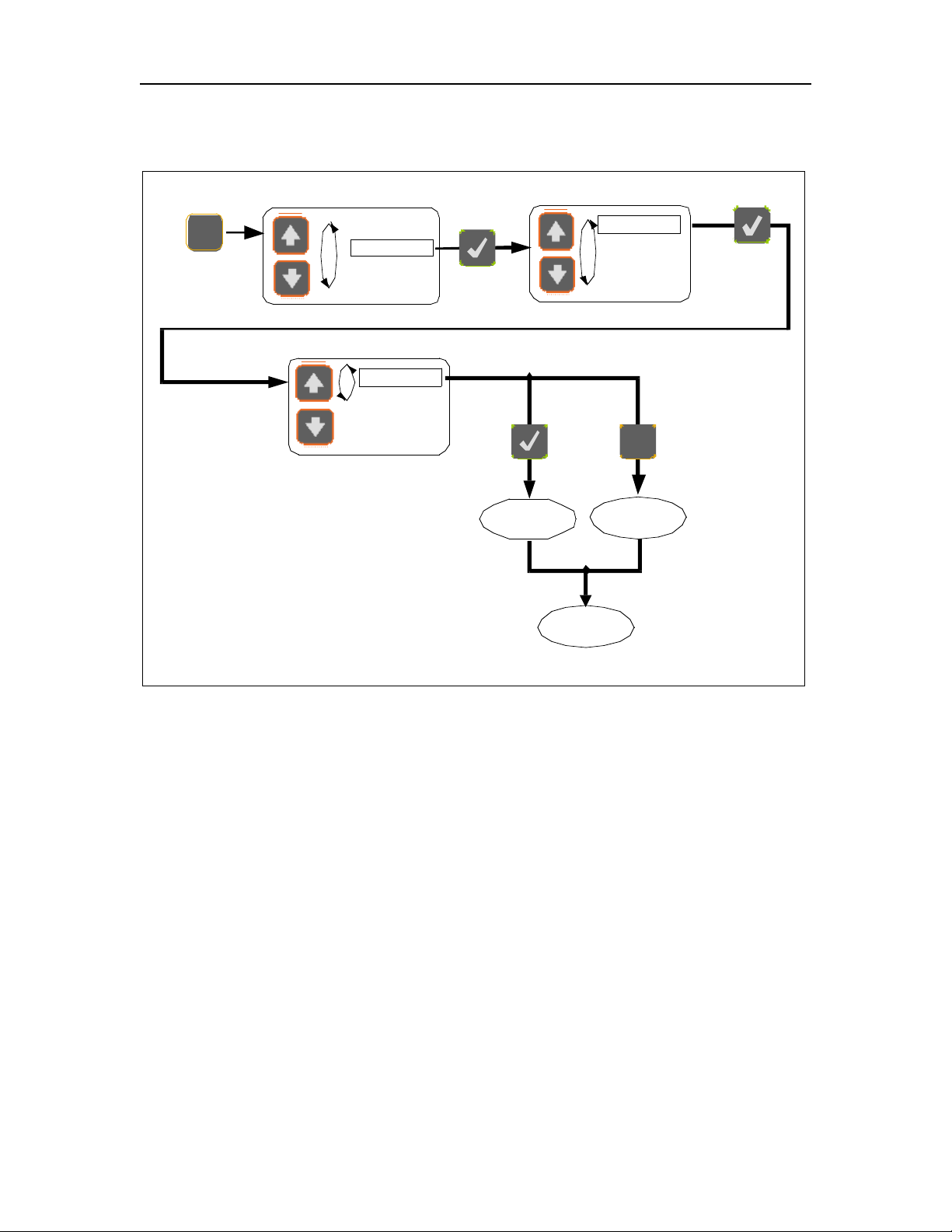
4.2.4 Delete Defined Sensor
A defined sensor can be deleted from the FOH201 memory as described in Figure 6.
When a sensor is being deleted, a confirmation message is displayed, for example Del
T101. To accept deleting the sensor, press the confirmation button or use Menu
Button
MENU
or the Null button
NULL
to cancel the operation.
4.3 System Setting
The functions below are used to setup specific parameters of the FOH201. Some of the
settings are not necessary related to a specific sensor.
4.3.1 Average
The user can set ON or OFF the averaging mode (ON by default). When on, the
measurements either displayed on the front panel display, output on the analog output or
on the RS-232 port is the result of the average of twenty sequential measurements
based on the running average method. So even when averaging takes place, the output
on the analog output is refreshed at a rate given by the sampling rate of the FOH201.
Note that the front panel display is refreshed a rate never higher than 3 measurements
per second. The method to set the averaging is described in figure 7. This parameter is
not saved and is lost when the system is switched off.
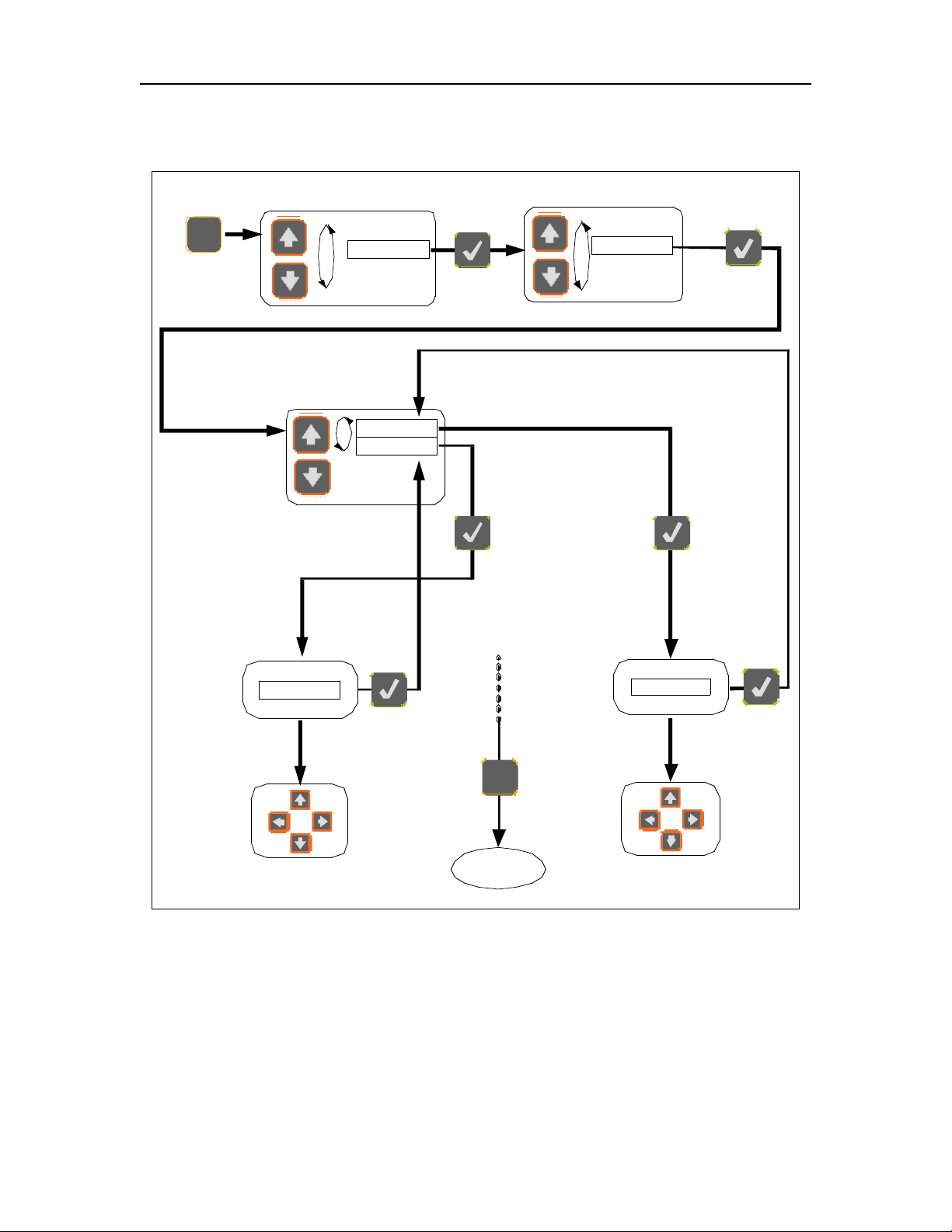
4.3.2 Analog output
The analog output parameters comprise the scale factor and the offset. The scale factor
corresponds to the physical unit per Volt (unit/V) outputted by the system, while the
offset corresponds to the physical value at which the user may want the analog output to
be at zero volt. For example, one may desire to have 10oC/V, being offset at 5oC. The
analog output voltage is thus given by:
Temperature = [Voltage output] x 10oC/V + 5oC.
The method to change the analog output parameters is described in Figure 8. A default
value is defined by the FOH201 to give access to the whole available range. Any new
scale factor is saved in the non-volatile memory. This value is used whenever the
system is switched on and off, and whenever the sensor is de-selected and re-selected.
If the sensor is deleted, then its analog scale factor is lost. By default, the offset value is
0. New offset value is not saved and it is lost when the system is switched off, or when
the sensor is de-selected.
Page 14
12
4.3.3 Auto
(Reserved for future use)
4.3.4 Unit Mod
The FOH201 signal conditioners has two types of units to display and to output the
measurement readings: the physical unit mode (°C, bar, etc depending of the Sensor
Type) and the nanometer unit mode which provides a measurement of the cavity length
of the sensor interferometer. The physical unit mode is the default mode and it is used
most of the time. The nanometer unit mode is useful for establishing the calibration
curve of the sensor that is the cavity length as a function of the measurand (pressure,
temperature, etc.). For practical reasons, OMEGA use the cavity length for calibrating
its sensors. The cavity length is defined as half of path length difference of the
interferometer. In the case of a Fabry-Perot interferometer, this length corresponds to
the distance in between the two mirrors of the interferometer.
4.4 System Diagnostic
The user can look through a variety of FOH201 internal parameter for diagnosing
potential problem with the system as described in Figure 10. The available diagnostics
parameters are shown below. Diagnostic values can be refreshed by depressing
confirmation button .
Parameters
Description
Lg 2.6V(volt)
Light level
Ga 1.3(no unit)
Amplifier gain
Lm 47% (%)
Lamp driving level
Ct 18 %(%)
Signal contrast
SNR 485(no unit)
Signal quality
The following table shows diagnostic values with good signal, poor signal, or with a
broken sensor (“fault”). A fault condition results in a “No Signal” being displayed.
Parameter
Good signal
Poor Signal
Fault
Lg
> 2.2
< 2.2
—
Ga
< 2.0
> 2.0
—
Lm
< 90 %
> 90 %
—
Ct
> 15 %
< 15 %
—
SNR
> 200
< 200
< 100
NOTE: Without a sensor connected, the instrument shows the message “NoS” or
“No Signal” on its display.
Page 15

13
In the unlikely situation that this message appears while a sensor is connected to the
unit, take note of the diagnostic parameters and contact OMEGA's technical support.
During a No Signal condition, the analog output and the serial ports output constant
values as follow:
Output
No Signal condition output value
Analog
0 Volt
RS-232
65 536.0
4.5 Calib
(Reserved for future use)
4.6 Null button
The Null button is used to cancel an operation that takes place within the menu, and exit
the menu. In the display mode the null button is used for zeroing the selected sensor, i.e.
referencing the sensor to the actual value. For example, when using a strain gauge, it is
always required to zero the sensor at a known zero strain state. Depending on the type
of sensor being used, the null button will perform differently.
4.6.1 Type T1, T2 Temperature sensors
A temperature sensor can not be zeroed using the null button. These temperature
sensors always give an absolute measurement.
4.6.2 Type P2, P3, Pv, Pm Pressure sensors; Type S1 strain sensors
Zeroing a P2 or P3 type pressure sensor, or a S1 type strain sensor always reference
the sensor to the actual value as shown in figure 10. Right after being zeroed, the sensor
will output a measured value that is close to zero. It is important to maintain the sensor
into a stable measurement condition while making a zero operation. The Pv-type sensor
cannot be zeroed using the null button.
4.6.3 Type N and X
These types cannot be zeroed.
Page 16
14
4.7 Defining a sensor (Menu levels)
Probes
Setting
Diag.
Calib.
Edit ParametersMode
MENU
Main Menu
Def Pr
Sel Pr
Mod Pr
Del Pr
Probe Menu
Type T1
Type T2
Type P1
Type P2
Type N1
Type N2
Type X1
Type X2
Define Probe Menu
Pr T101 GF0 100 GF1 100
Pr T101 GF0 100 GF1 100
Visualize parameters Mode
NULL
Exit to data
display
Edit parameters
with cursors
DEF
Figure 3: Defining a sensor
Sensor Type and Gauge Factor(s) must first be entered into the FOH201 memory to
permit the conversion of the sensing interferometer path length difference into physical
measurements.
Page 17
15
4.8 Selecting a sensor (Menus levels)
Sel T101
Sel T202
Sel P203
Sel T108
Probes
Setting
Diag.
Calib.
MENU
Main Menu
Def Pr
Sel Pr
Mod Pr
Del Pr
Probe Menu
Pr P203 GF0 1000
Visualize parameters Mode
Exit to data
display
SEL
Select Probe Menu
NULL
No Probe
Select
Probe
Selected
Figure 4: Selecting a sensor
Sensor must be selected among those defined into the FOH201 internal memory.
Page 18
16
4.9 Modifying Gauge Factor(s) (Menus levels)
Mod T101
Mod T202
Mod P203
Mod T108
Probes
Setting
Diag.
Calib.
Edit ParametersMode
MENU
Main Menu
Def Pr
Sel Pr
Mod Pr
Del Pr
Probe Menu
Pr T101 GF0 100 GF1 100
Pr T101 GF0 100 GF1 100
Visualize parameters Mode
NULL
Exit to data
display
Edit parameters
with cursors
Modify Probe Menu
+
Figure 5: Modifying Gauge Factor(s)
Gauge Factors saved into the internal memory can be modified.
Page 19
17
4.10 Delete Gauge Factor (Menus levels)
Probes
Setting
Diag.
Calib.
MENU
Main Menu
Def Pr
Sel Pr
Mod Pr
Del Pr
Probe Menu
Del T101
Del T202
Del P203
Del T108
Delete Probe Menu
Pr P203 GF1 1000
Visualize parameters Mode
NULL
Exit without
deleting
Confirm?
Figure 6: Delete Gauge Factor
Gauge Factors can be deleted from the internal FOH201 memory.
Page 20
18
4.11 Averaging measurements (Menus levels)
Probes
Setting
Diag.
Calib.
MENU
Main Menu
Average
Analog
Auto
Unit Mod
Setting menu
Aver. On
Aver.Off
Average Setup Menu
Exit to data
display
Selection
Rejected
Selection
Accepted
NULL
Figure 7: Averaging measurements
Averaging: twenty sequential measurements are averaged (running average method) for
obtaining even smoother signal.
Page 21
19
4.12 Setting the analog output (Menus levels)
Probes
Setting
Diag.
Calib.
MENU
Main Menu
Average
Analog
Auto
Unit Mod
Setting Menu
Scaling
Offset
Analog Setup Menu
0010oC/V
Edit Analog
Scaling Output
Edit parameters
with cursors
+0000oC
Edit Analog
Offset Output
Edit parameters
with cursors
NULL
Exit
Figure 8: Setting up Analog output
Both the scale factor and offset can be setup according to user requirements.
Page 22
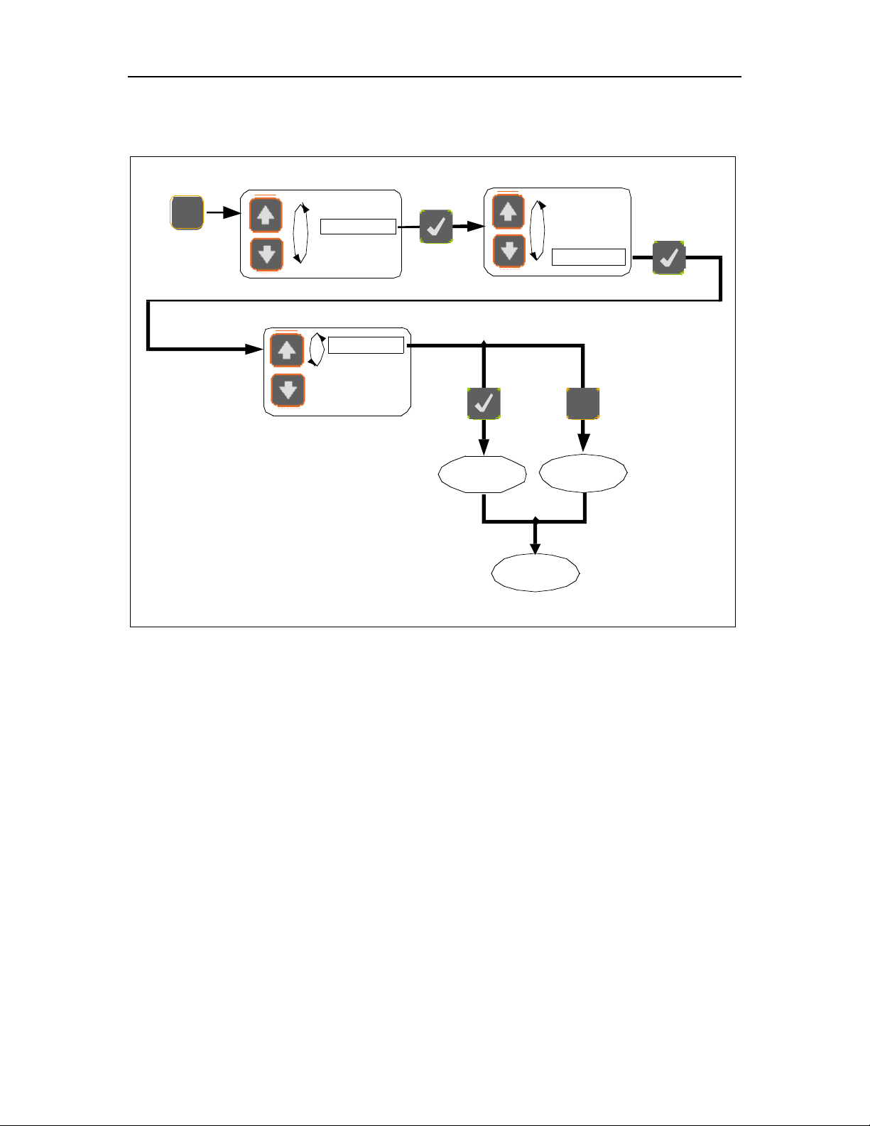
20
4.13 Unit mode (Menus levels)
Probes
Setting
Diag.
Calib.
MENU
Main Menu
Average
Analog
Auto
Unit Mod
Setting menu
Physical
nm
Unit Mode menu
Exit to data
display
Selection
Rejected
Selection
Accepted
NULL
Figure 9: Unit Mode
The user can select the signal conditioner to display and output the measurement
reading in physical units or in nanometer units.
Page 23
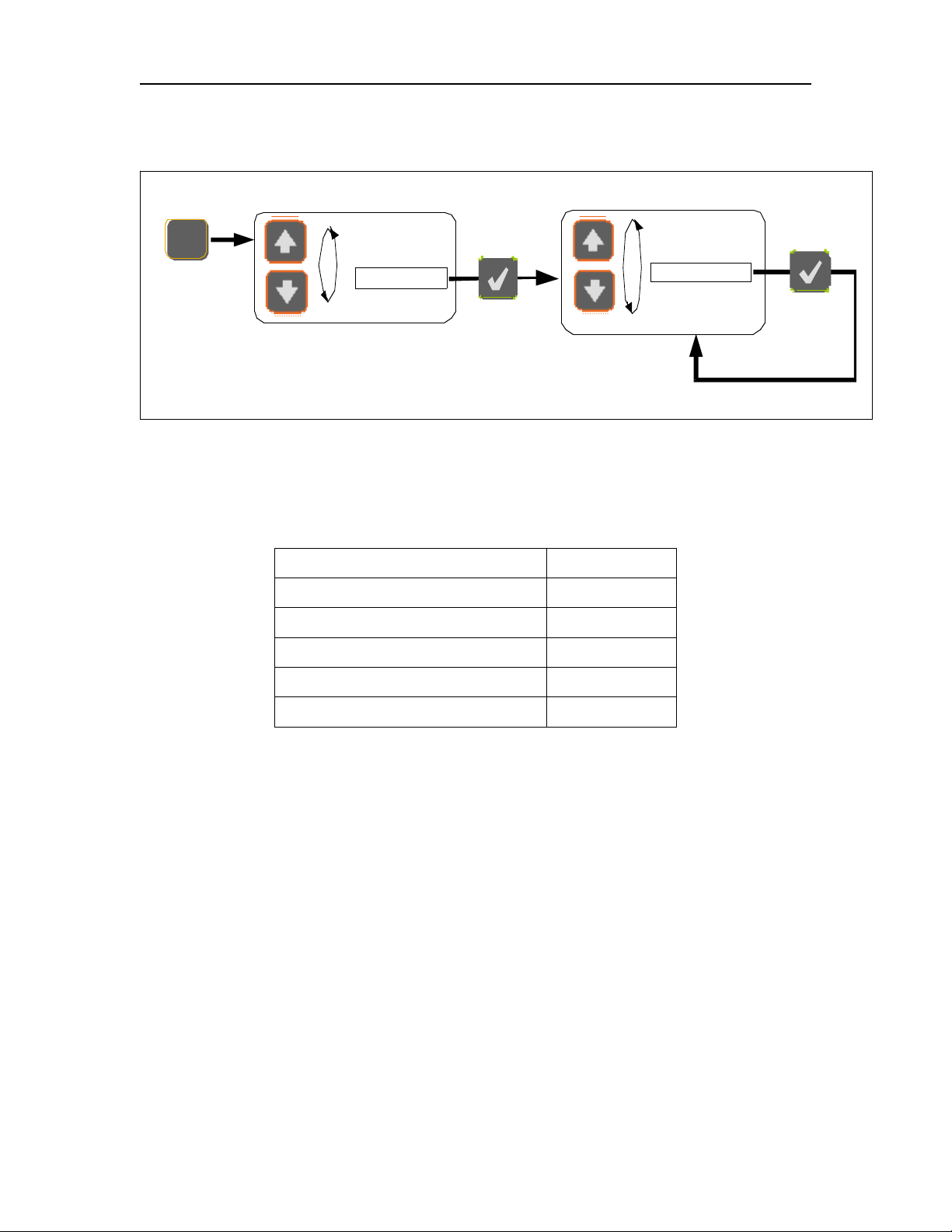
21
4.14 Diagnostic (Menus levels)
Lg 2.1V
SN 4800
Ct 26.7%
Lm 85.1%
Ga 1.3
Probes
Setting
Diag.
Calib.
MENU
Main Menu
Diagnostic Menu
Refresh Diagnostic
Figure 10: Diagnostic
• The user can look through a variety of diagnostic parameters for diagnosing
potential problem with the FOH201 or the fiber-optic sensor. The available
diagnostic parameters are as follows.
Diagnostic parameters:
Unit
Light level (Lg)
Volts
Signal-to-noise ratio (SN)
(no unit)
Signal contrast (Ct)
%
Lamp driving level
%
Amplifier gain (Ga)
(no unit)
Page 24
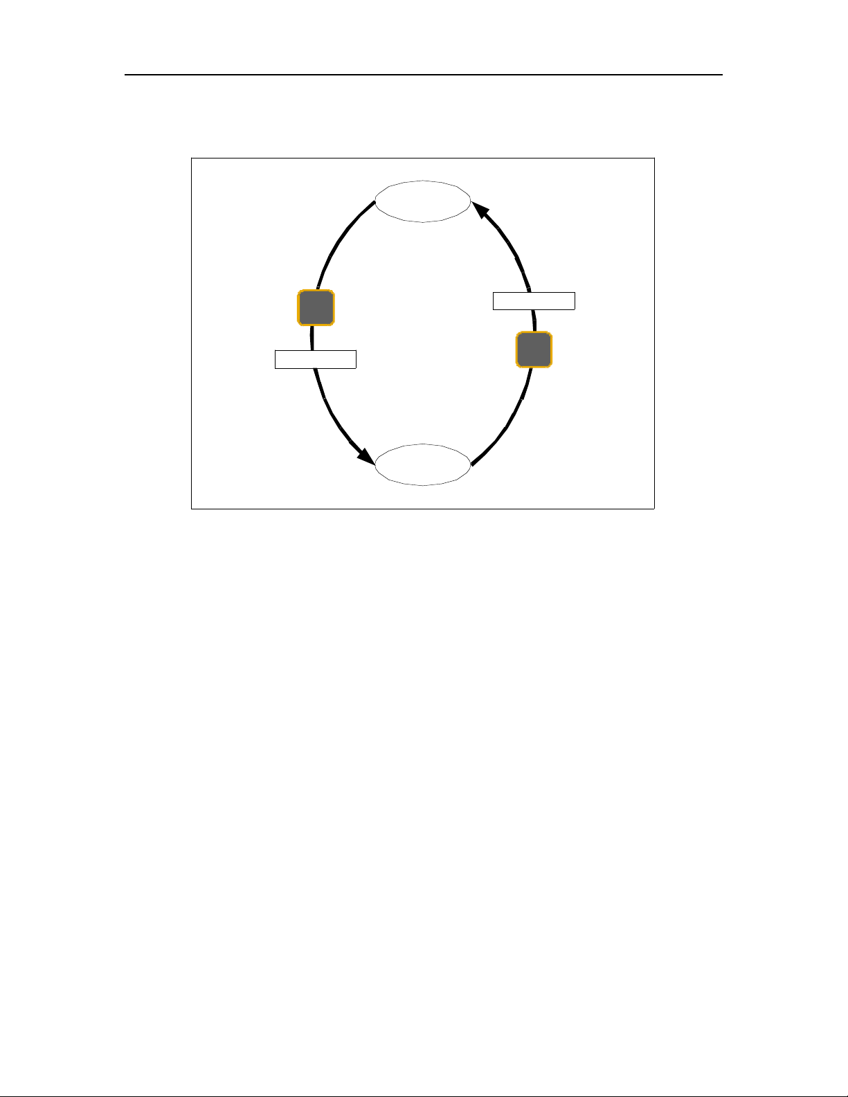
22
4.15 Zeroing pressure sensor of P2, P3 type; Strain sensor of S1
Type (Menus levels)
NULL
Display
Nul P201
Display
NULL
Nul P201
Figure 11: Zeroing Pressure sensor Type P2, P3, Pm; Strain sensor Type S1
Zeroing a pressure or strain sensor always reference the sensor to the actual value, so
that the output value becomes zero right after the zeroing operation.
Page 25
23
5. Remote operation
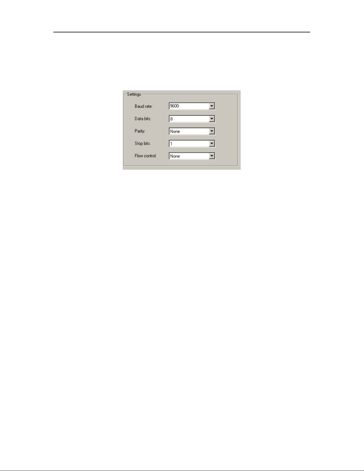
OMEGA's FOH201 signal conditioner comes with a RS-232 serial communication
interfaces to allow control with a remote computer. The RS-232 interface settings are
indicated on the following figure.
Figure 12: RS-232 interface setting
The FOH201 serial interface remote control commands are based on the standard SCPI
syntax (Standard Commands for Programmable Instrumentation). The user can create
its own remote control software using the various SCPI commands available for the
FOH201. But for ease of operation, OMEGA provides its own control software, called
SoftSens, which gives access to all the functionalities of the FOH201 conditioner. See
SoftSens user manual for how to remotely control the FOH201 conditioner.
For those who which to develop their own remote control software, ask for OMEGA
Serial communication user manual to get all the information about serial interfacing with
OMEGA's signal conditioners.
Page 26

24
6. Specifications
Number of channels
One
Compatibility
All Opsens WLPI transducers
Full scale
30 000 nm (path length difference)
Resolution
±0.003 % of F.S. (no averaging)
Precision
±0.01 % of F.S. @ ±3.3 sigma limit (99.9 % confidence
level)
Sampling rate
20 Hz standard
Output interface
±5 Volts and RS-232 standard
Input power
9 to 24 VDC (AC/DC wall-transformer adapter included)
Consumption
1.8 Watts typical
Battery
9V
Enclosure
Plastic casing with a removable rubber boot protection
Dimensions (without rubber boot protection)
45 mm (H) x 105 mm (W) x 165 mm (L)
Storage temperature
-40 °C to 65 °C
Operating temperature
0 °C to 45 °C
Humidity
95 % non condensing
Light source life span
40 000 hours MTBF
Page 27
0
Page 28

Where Do I Find Everything I Need for
Process Measurement and Control?
OMEGA…Of Course!
Shop online at omega.com
TEMPERATURE
Thermocouple, RTD & Thermistor Probes, Connectors, Panels & Assemblies
Wire: Thermocouple, RTD & Thermisto
Calibrators & Ice Point References
Recorders, Controllers & Process Monitors
Infrared Pyrometers
PRESSURE, STRAIN AND FORCE
Transducers & Strain Gages
Load Cells & Pressure Gages
Displacement Transducer
Instrumentation & Accessories
s
FLOW/LEVEL
Rotameters, Gas Mass Flowmeters & Flow Computers
Air Velocity Indicators
Turbine/Paddlewheel Systems
Totalizers & Batch Controllers
r
pH/CONDUCTIVITY
pH Electrodes, Testers & Accessorie
Benchtop/Laboratory Meters
Controllers, Calibrators, Simulators & Pumps
Industrial pH & Conductivity Equipment
s
DATA ACQUISITION
Data Acquisition & Engineering Software
Communications-Based Acquisition System
Plug-in Cards for Apple, IBM & Compatibles
Datalogging System
Recorders, Printers & Plotters
s
HEATERS
Heating Cable
Cartridge & Strip Heaters
Immersion & Band Heaters
Flexible Heater
Laboratory Heaters
s
ENVIRONMENTAL
MONITORING AND CONTROL
Metering & Control Instrumentatio
Refractometer
Pumps & Tubin
Air, Soil & Water Monitors
Industrial Water & Wastewater Treatment
pH, Conductivity & Dissolved Oxygen Instruments
s
g
n
s
M4385/1007
 Loading...