

Page 1
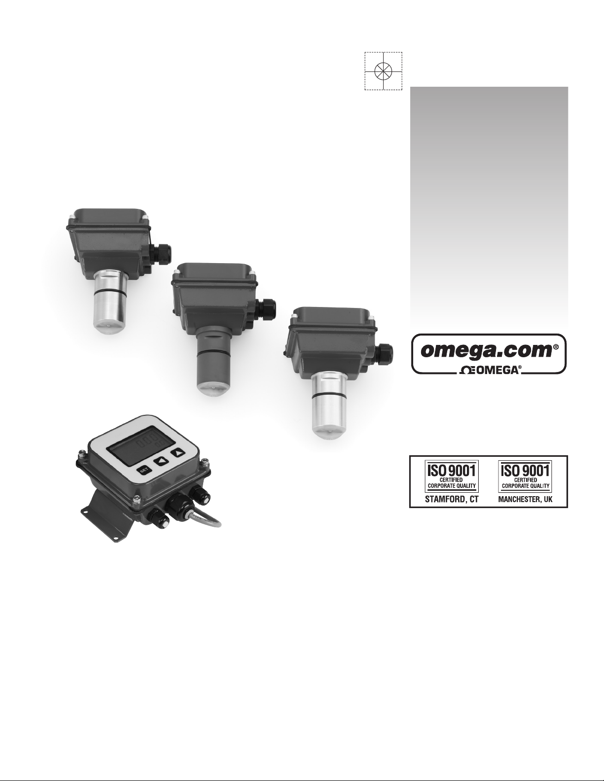
User’s Guide
Shop online at
omega.com
e-mail: [email protected]
For latest product manuals:
omegamanual.info
FMG980 SERIES
Electromagnetic Flow Sensor
Xxxxx Xxxxxxxx
XXXXXX
Page 2

OMEGAnet®Online Service Internet e-mail
U.S.A.:
ISO 9001 Certified
omega.com [email protected]
Servicing North America:
Omega Engineering, Inc., One Omega Drive, P.O. Box 4047
Stamford, CT 06907-0047 USA
Toll Free: 1-800-826-6342 TEL: (203) 359-1660
FAX: (203) 359-7700 e-mail: [email protected]
Canada:
976 Bergar
Laval (Quebec), Canada H7L 5A1
Toll-Free: 1-800-826-6342 TEL: (514) 856-6928
FAX: (514) 856-6886 e-mail: [email protected]
For immediate technical or application assistance:
U.S.A. and Canada: Sales Service: 1-800-826-6342/1-800-TC-OMEGA
Customer Service: 1-800-622-2378/1-800-622-BEST
Engineering Service: 1-800-872-9436/1-800-USA-WHEN
Mexico: En Español: 001 (203) 359-7803 FAX: (001) 203-359-7807
®
®
®
Servicing Europe:
Benelux:Managed by the United Kingdom Office
Czech Republic: Frystatska 184
733 01 Karviná, Czech Republic
Toll-Free: 0800-1-66342 TEL: +420-59-6311899
FAX: +420-59-6311114 e-mail: [email protected]
France:
Managed by the United Kingdom Office
Toll-Free: 0800 466 342 TEL: +33 (0) 161 37 29 00
FAX: +33 (0) 130 57 54 27 e-mail: [email protected]
Germany/Austria: Daimlerstrasse 26
D-75392 Deckenpfronn, Germany
Toll-Free: 0 800 6397678 TEL: +49 (0) 7059 9398-0
FAX: +49 (0) 7056 9398-29 e-mail: [email protected]
United Kingdom: OMEGA Engineering Ltd.
ISO 9001 Certified One Omega Drive, River Bend Technology Centre, Northbank
Irlam, Manchester M44 5BD England
Toll-Free: 0800-488-488 TEL: +44 (0)161 777-6611
FAX: +44 (0)161 777-6622 e-mail: [email protected]
It is the policy of OMEGA Engineering, Inc. to comply with all worldwide safety and EMC/EMI
regulations that apply. OMEGA is constantly pursuing certification of its products to the European New
Approach Directives. OMEGA will add the CE mark to every appropriate device upon certification.
The information contained in this document is believed to be correct, but OMEGA accepts no liability for any
errors it contains, and reserves the right to alter specifications without notice.
WARNING: These products are not designed for use in, and should not be used for, human applications.
Page 3

TABLE OF CONTENTS
SECTION I FLOW METER INSTRUCTIONS
General Information
Features, Specications .......................................................................................................................................Page 1
Installation
Distorted Flows, Fitting Installation, Chemical Injection or Fertigation, Meter Installation,
Positioning the Meter ............................................................................................................................................Page 2
Straight Pipe Recommendations .........................................................................................................................
Full Pipe Recommendations .................................................................................................................................Page 4
Electrical Connections
General Electrical Guidelines, Power, Forward Flow Output, Reverse Flow Output,
Grounding Guidelines, Grounding Diagram.........................................................................................................Page 5
Operation & Maintenance
Zero Adjustment, Minimum Flow, Flow Rate Table, Presence of Flow Indication,
Filtering, Electrode Coating, Calibration (“K-Factor”), K-Factor Chart ...............................................................Page 6
Caution & Troubleshooting
Problems, Probable Causes .................................................................................................................................Page 7
Page 3
SECTION II FLOW COMPUTER INSTRUCTIONS
General Information
Features, Specications .......................................................................................................................................Page 8
FMG980 Installation and Settings
Wall Mounting, K-Factor, Reading in Other Units, Changing Volume Units, Changing Time Units,
Settings, Set K, Set P/Flow Alarm, Set 20 mA, Set Decimal Point, Set Time Unit ............................................
FMG980 Connections and Operation
Counter or PLC, FMG980 Display and Proportional Feed ..................................................................................Page 10
FMG980 & 4-20 mA Output, Dual FMG980 Displays (Example of Bidirectional Connection) ........................Page 11
FMG980 Connection Diagram, FMG980-M and FMG980-W Operation ..........................................................Page 12
Quick Settings
Quick Settings Overview .......................................................................................................................................Page 13
FMG980 Troubleshooting
Problems, Probable Causes .................................................................................................................................Page 14
Page 9
Page 4
SECTION I: FMG980 SERIES FLOW METER INSTRUCTIONS
GENERAL INFORMATION
FMG980 series insertion electromagnetic flowmeters are
designed for use with conductive liquids in 1” to 12” pipe. A
choice of materials (stainless steel, brass, and PVC) allows
the meter to adapt to a range of temperature, pressure, and
corrosive environments.
The FMG980 series are highly suitable for difcult applications
with changing viscosities and pulsating ows, such as airdriven diaphragm pumps. With no moving parts, these meters
can be used in “dirty” applications where debris would foul a
mechanical meter. Like all magmeters, when used in chemical
injection applications, these meters should be installed
upstream of the chemical line (or far enough downstream to
allow complete mixing of uids before the meter).
Designed for modularity and versatility, the FMG980 series
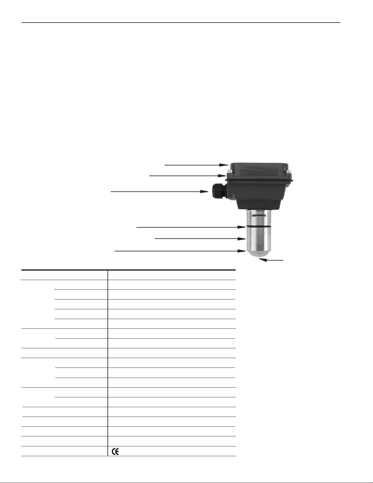
FEATURES
Cover, or transmitter or indicator module
Powder coated aluminum housing
Cable strain relief
has a current-sinking pulse output that can be combined with
the appropriate transmitter or indicator for the application. For
analog output and display of rate and total, an FMG980 can be
used. Modules can be wall- or meter- mounted. If the FMG980
series meter is used with a programmable controller, the output
signal can be fed direct, with no other conditioning required.
FMG980 series xed depth insertion meters require special
ttings. Factory installation in the tting ensures correct depth
placement in the pipe. An FMG980 series meter can be ordered
in a full power model when a source of electricity is available, or
in a low power model that can run on an external battery with
solar panel.
Reverse ow output and immersibility are optional.
O-ring, EPDM (FKM optional)
Sensor body (Stainless, Brass, PVC)
PVDF electrode cap
SPECIFICATIONS*
Pipe Size
Materials Mechanical
Electrodes
Housing
Electrode Cap
O-Ring
Power Full Power
Low Power
Flow Rate
Temperature Ambient Temp
Fluid Temp : Brass/SS
Fluid Temp: PVC
Pressure Brass/SS
PVC
Minimum Conductivity
Calibration Accuracy
Output
Empty Pipe Detection
Regulatory
*Specications subject to change
Page 1
Hastelloy electrodes
1” to 12”
316 SS/Brass/PVC
Hastelloy
Cast powder-coated aluminum
PVDF
EPDM standard (FKM optional)
12 - 25 Vdc, 250 mA
12 - 25 Vdc, 40 mA average with 250 mA peaks
0.28 - 20 ft/sec (0.08 - 6.09 m/sec)
0˚ to 160˚ F (-17˚ to 72˚ C)
32˚ to 200˚ F (0˚ to 93˚ C)
32˚ to 130˚ F (0˚ to 55˚ C) @ 0 psi
200 psi (13.8 bar)
150 psi (10 bar) @ 75˚ F
20 microSiemens/cm
+/- 1% of full scale
Square wave pulse, opto isolated, 550 Hz @ 20 ft/sec
Software, defaults to zero ow
Mark (Stainless Steel, Brass and Standard Power Only)
Page 5
INSTALLATION
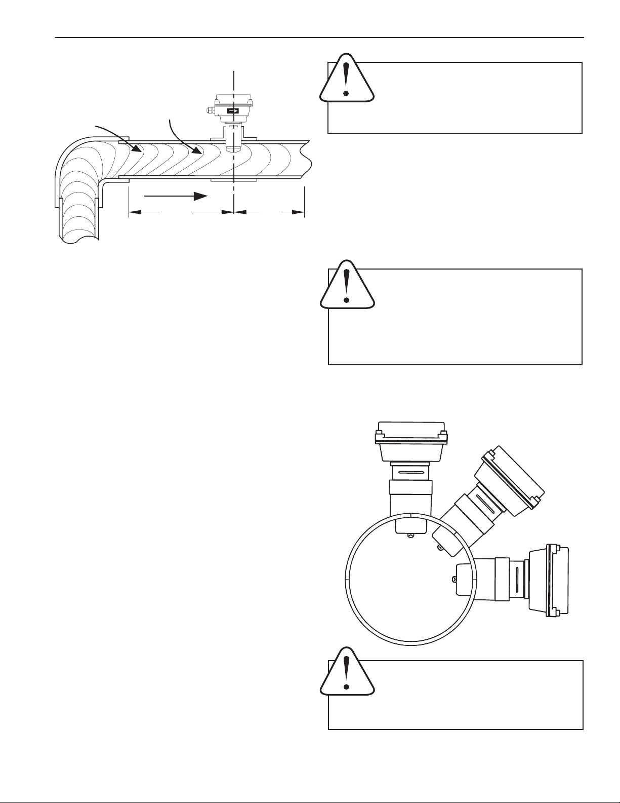
DISTORTED FLOWS
Faster Flow
Distorted
Flow Prole
Fitting Installation. FMG980 series meters require special
ttings that ensure that the ow sensor is installed to the
correct depth. The tting must be installed in the pipeline
before the meter can be installed. For best results, install
with at least ten diameters of straight pipe upstream of the
meter and ve diameters downstream (or more under specic
adverse circumstances). See diagrams, next page.
Causes Meter
To Read High
10X
5X
Caution: In chemical injection or fertigation
applications, install chemical injection point
downstream of magmeter, or far enough
upstream to allow complete mixing of uids
before the meter.
Meter Installation. After the meter tting is installed in the
pipeline, the meter can be installed in the tting. After noting
the direction of the ow arrow, press the meter into the tting
as far as it will go. Retain the meter in place by inserting the
U-clip. The pin can be installed from either side. It may be
necessary to rotate the probe back and forth slightly to start
the pin into the slots on the probe. Slide the pin in as far as
it will go.
Caution: These ow sensors are not recommended for installation downstream of a
boiler feedwater pump where installation
fault may expose the ow sensor to boiler
pressure and temperature. Maximum recommended
temperature is 130°F (Plastic), 200°F (Metal).
If there is not enough straight run to smooth out the turbulence caused by valves, ttings, and changes in direction,
some decrease in accuracy may result. This does not mean
that the ow meter’s reading is meaningless, however. In
some applications (control systems, valve operation, chemical addition), a repeatable reading may be more important
than a highly accurate one.
Although FMG980 series PVC meter tees are supplied with
some straight pipe, additional straight pipe should be added
to meet straight pipe recommendations. It is not advisable to
connect a ow-disturbing device (e.g. valve or elbow) directly
to the end of these ttings.
A PVC tting is usually installed by solvent welding. The stainless steel and brass meter ttings have female pipe threads,
requiring the appropriate male threaded ttings. Saddle or
weld ttings (3” and above) require a hole to be cut in the
pipe. Recommended hole size is 1-3/4”.
Chemical Injection or Fertigation. When any magmeter, by
any manufacturer, is used in a chemical injection application
(including fertigation), the chemical injection point must be
placed downstream of the magmeter OR far enough upstream
for complete mixing to occur before the uid reaches the
meter. When unmixed chemical or fertilizer alternates with
water passing through the meter, the rapid changes in conductivity may cause sudden spikes and drops in the meter’s
reading, resulting in inaccurate measurement. The magmeter
will restabilize, however, with a steady ow of uid of uniform
conductivity.
POSITIONING THE METER
Okay position if there is no
air in the pipe
BEST POSITIONS
Caution: Never remove the U-clip retainer
when the pipe is under pressure. Always
remove pressure from the pipe before you
attempt to remove the meter. Removal under
pressure may result in damage or serious injury.
Page 2
Page 6
INSTALLATION
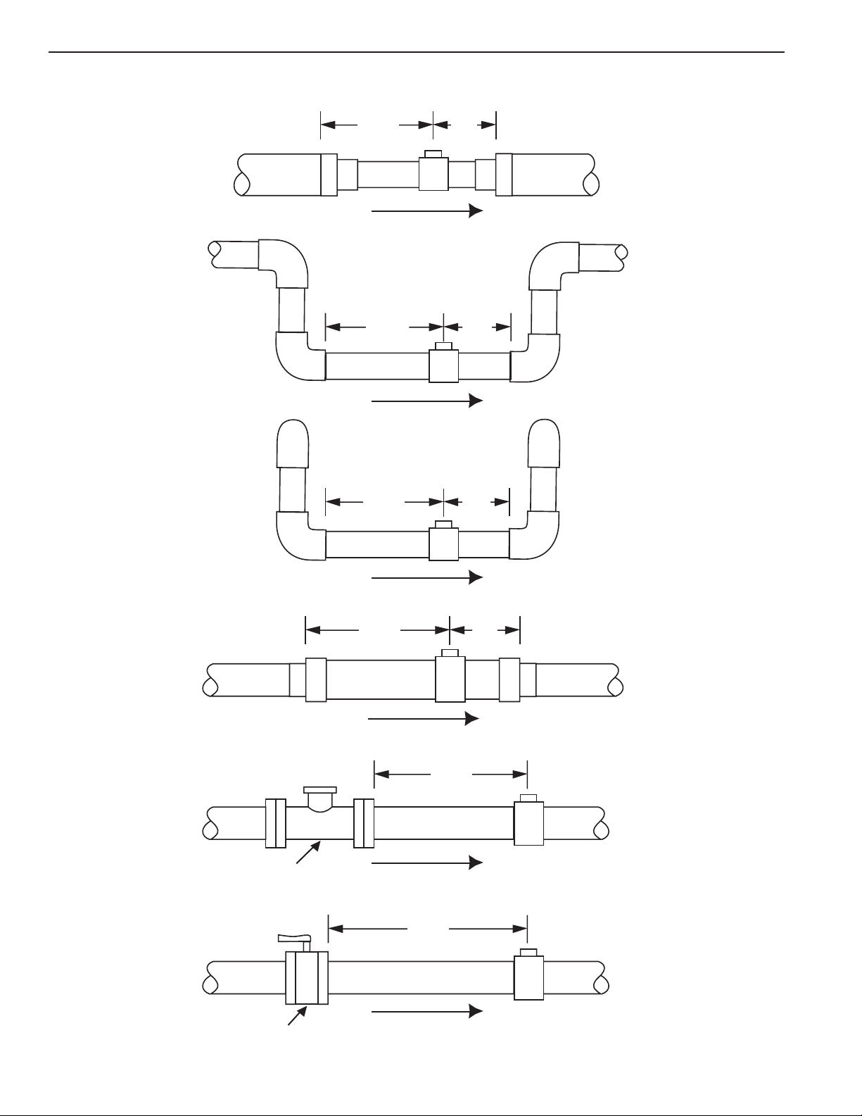
STRAIGHT PIPE RECOMMENDATIONS
(X = pipe diameter)
Reduced Pipe
Two Elbows In Plane
Two Elbows, Out Of Plane
10X
20X
5X
5X10X
5X
Expanded Pipe
Spiral Flow
Swirling Flow
Propeller Meter
Partially Open
Buttery Valve
20X
5X
30X
50X
Page 3
Page 7
INSTALLATION
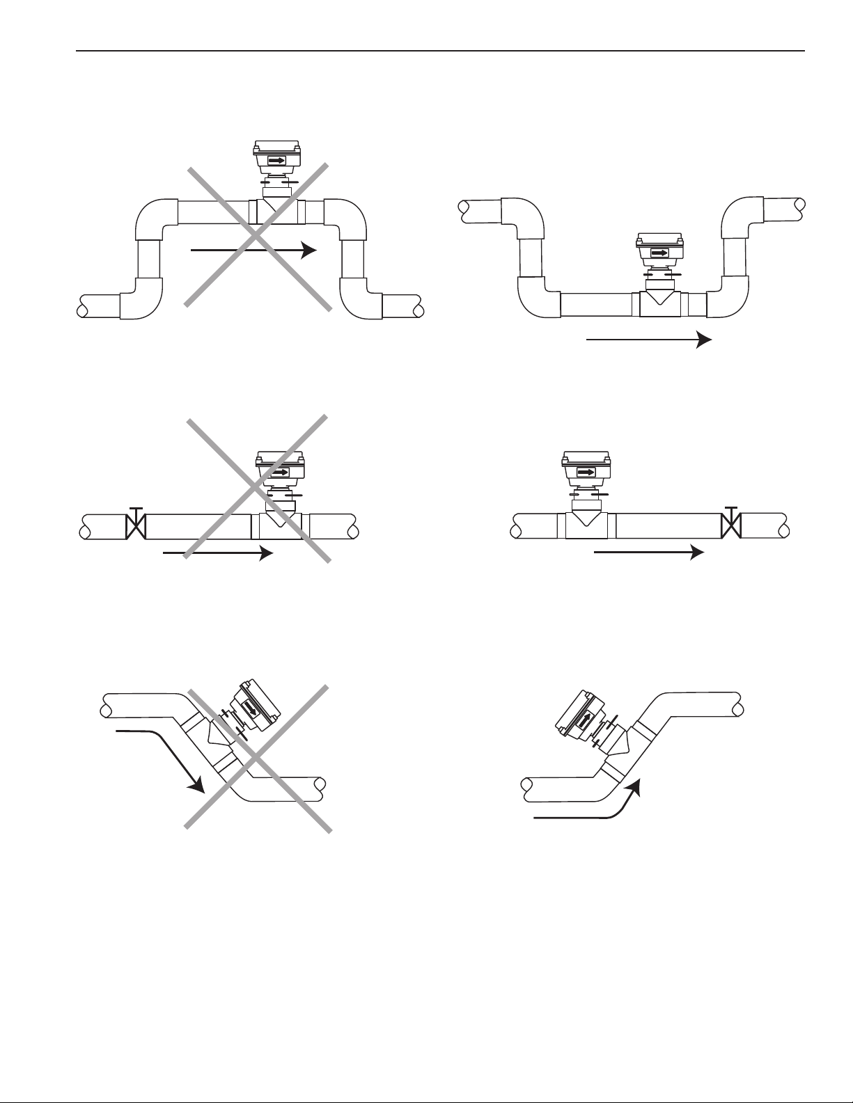
FULL PIPE RECOMMENDATIONS
Possible Problem:
Allows air pockets to form at sensor
Better Installation:
Ensures full pipe
Possible Problem:
Post-valve cavitation can create air pocket
Possible Problem:
Air can be trapped
Better Installation:
Keeps pipe full at sensor
Better Installation:
Allows air to bleed off
Page 4
Page 8
ELECTRICAL CONNECTIONS
General Electrical Guidelines:
• Whenever possible avoid running control cables in
the same conduit with or bundled with AC power.
• Using shielded cable, be sure to connect shield to
ground at power supply end of the cable.
• Avoid routing ow sensor cables in close proximity to
a variable frequency drive.
• Recommended power and output wiring is shielded
twisted pair 18-22 AWG control cable.
• Recommended voltage is 12-24 Vdc. Note that
unregulated power supplies can vary from nameplate
voltage by a considerable amount, especially with AC
line voltage uctuation. Therefore 24V power supplies
must be regulated.
See the Connections diagrams on the following pages for the
appropriate terminals.
Power: A 12 - 24 Vdc power supply capable of at least 250
mA current output is needed.
Forward Flow Output: This open-collector isolated output
does not supply power. This pulse is generated in the forward
ow direction on the standard unit. (Reverse ow output is
available as an option).
Note: This output is limited to 6 mA at 30 Vdc maximum.
Reverse Flow Output: Reverse ow output is available as
an option. This open-collector isolated output does not supply
power. It functions like a polarity-sensitive switch closure.
Note: This output is limited to 6 mA at 30 Vdc maximum.
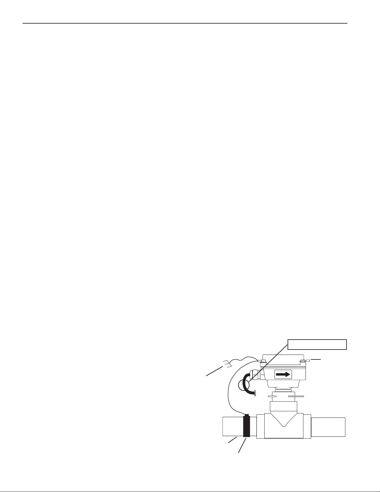
Grounding Guidelines:
For best results, use a good quality earth ground, such as
metallic water piping or a driven ground, to ensure a good
connection to earth ground and good noise suppression.
If the ow sensor is installed in metallic piping, for optimum
connection clamp wire to the piping a short distance to one
side of the ow sensor using an electrical grounding clamp.
Connect the wire to the earth ground and to one of the housing
screws.
For Non-Metallic Pipe: Connect one to the housing screws
by wire to a good earth ground, such as metalic water piping
or a rod driven into the ground.
EX meters are usually unaffected by moderate levels of electrical noise. In some applications performance may be improved
by taking the following steps:
• Use shielded twisted pair cable (Belden 8723 or
equivalent above ground or Alpha 35482 or
equivalent burial).
• Clamp a ferrite bead (Steward 28A2029-OAO or
equivalent) on meter signal/power wire within 3/4”
of the meter strain relief (tape or tie wrap in place
if necessary). See diagram below.
Page 5
• IMPORTANT - Connect the cable shield ground
wire to ground, ONLY at power supply end of cable.
GROUNDING DIAGRAM
PLACE FERRITE BEAD HERE
Earth
Ground
Metallic Pipe
Grounding Clamp
Page 9
OPERATION & MAINTENANCE
10031295
EF81T-P200
K:158.42
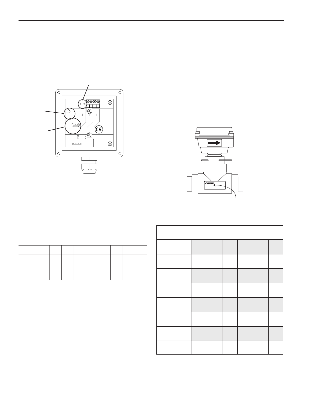
Zero Adjustment. When the FMG980 series is powered up
and there is no ow, there should be no output pulses (or, if
connected to the FMG980, ow rate should read “0”). If there
are pulses it may be necessary to adjust the ow meter under
no-ow conditions after it has been installed. This should only
be done if the indicated ow is low, near the lower cutoff.
Reverse Output Option
Status
LED
Zero
Adjust
Status
LED
Zero
Adj
345621
Forward
Output
Max. 6mA
30Vdc
+
-+-
Power
12-24Vdc
unauthorized repair
Warranty is void if
is attempted!
NOTICE
Pins
To perform the adjustment, after determining that there is a full
pipe with no ow, short between the two pins marked “Zero
Adjust”. A red LED light will come on for approximately 50
seconds and then go out. The zero adjustment is completed.
Minimum Flow. As with any other ow sensor, there is a rate
below which the FMG980 series sensor cannot read. Check
the ow rate table below for the minimum ow rate detectable
by the sensor for a given pipe size.
FLOW RATE (GPM)
Nominal
Pipe Size
• Min
@ 0.28 ft/sec
• Max
@ 20 ft/sec
1” 1-1/2” 2” 3” 4” 6” 8” 10” 12”
.7 1.5 2.7 6 11 25 44 69 99
49 110 196 440 783 1760 3130 4900 7050
Electrode Coating. Grease or other adhering, non-conductive
materials can stop ow detection if the electrodes become
heavily coated. To clean the electrodes, remove the sensor
from the pipe and gently scrub the electrodes (three silver
bumps) on the reading face of the ow sensor. A mild soap
(dishwashing liquid for example) can be used to aid the
cleaning process.
Calibration (“K-factor”). The K-factor represents the actual
number of pulses per gallon the meter produces during a ow
test. This number can be entered into your electronic control
to make it read properly. The FMG980 series meter is ordered
with a tee tting. The ttings have been factory tested and the
K-factor is indicated on the side of the tting (see diagram).
Find Your K-Factor Here
If the FMG980 series meter is ordered with a saddle or wel-
dolet tting, nd your K-factor in the chart below.
K-FACTORS SADDLES & WELDOLETS
3” 4” 6” 8” 10” 12”
PVC/Steel
Sch. 40
PVC/Steel
Sch. 80
Stainless
Steel (10S)
70.397
78.748
62.385
40.985
45.360
36.626
18.130
20.084
16.510
10.497
11.495
9.642
6.674
7.322
6.173
4.709
5.184
4.373
Presence of Flow Indication. To assist in troubleshooting,
the “Status LED” has two blinking modes in normal operation.
When there is no ow detectable by the meter (below minimum
threshold) the LED blinks every 8.0 seconds. When there is
detectable ow, the same indicator blinks every 3.0 seconds.
Filtering. The software of the FMG980 series sensor lters
out electrical noise and averages sudden variations in the
ow to smooth the output. It takes a matter of seconds for
the ow sensor to get up to full output when it is powered up
or when ow begins.
Stainless
Steel (40S)
Copper Tubing
(Type L)
Copper Tubing
(Type K)
Brass Pipe
Duct. Iron
(Class 52)
70.397
76.371
78.371
70.672
57. 376
40.985
43.552
44.638
41. 517
37.320
18.130
19.513
20.223
17.778
16.915
10.497
11.201
11.622
10.445
9.503
6.674
7.230
7.500
6.674
6.197
4.661
5.016
5.239
4.661
4.325
NOTE: K-factors are in Pulses/gallon. For Pulses/Liter, divide
by 3.785.
Page 6
Page 10

CAUTION & TROUBLESHOOTING
Caution: The electronics of the FMG980 series meters are not eld-repairable.
Warranty is void if unauthorized repair is attempted
TROUBLESHOOTING
Problem
No pulse output
Output pulses
incorrect
Probable Cause Try...
Pipe not full
Below minimum ow cutoff
Unit not grounded
Excessive electrical noise
No power
Flow reversed
Power reversed
Output connections reversed
Fluid conductivity <20 microSiemens/cm
Missing or incorrect ground wire
Excessive electrical noise
Check plumbing
Check the presence of Flow LED (see pg. 9)
Connect to earth ground
Check for proper electrical wiring
Check for power across power
input terminals
Note ow direction arrow,
reverse direction of meter
Reverse connections
Change output connections
Select another ow meter
Check for proper ground
Check for proper electrical wiring
Jumpy reading
Page 7
Fluid conductivity <20 microSiemens/cm
Empty pipe
Not enough straight pipe
Rapidly changing conductivity (in chemical
injection or fertigation applications)
Select another ow meter
Check for full pipe or install meter in the vertical position
Check for ten diameters upstream AND ve
diameters downstream
Install chemical injection line downstream of
magmeter (or far enough upstream to allow
complete mixing of uids before meter)
Page 11
SECTION II: FMG980-M AND FMG980-W FLOW COMPUTER INSTRUCTIONS
GENERAL INFORMATION
These ow computers are microcontroller-based indicator/
transmitters that display ow rate and total and provide output signals. The FMG980 is powered by external DC voltage
and has both pulse and 4-20 mA analog outputs. When the
FMG980 is being used in the 4-20 mA mode, it is a “two-wire”
or “loop-powered” device, meaning that the 4-20 mA output
signal doubles as its power supply.
The addition of a dual-relay output board (-R2) allows for
certain applications requiring contact output isolation (e.g.,
certain metering pumps and water treatment controls). Dual
solid state relays provide exactly the same pulse output as
the standard unit, and each can signal one external device. A
non-resettable total is also available.
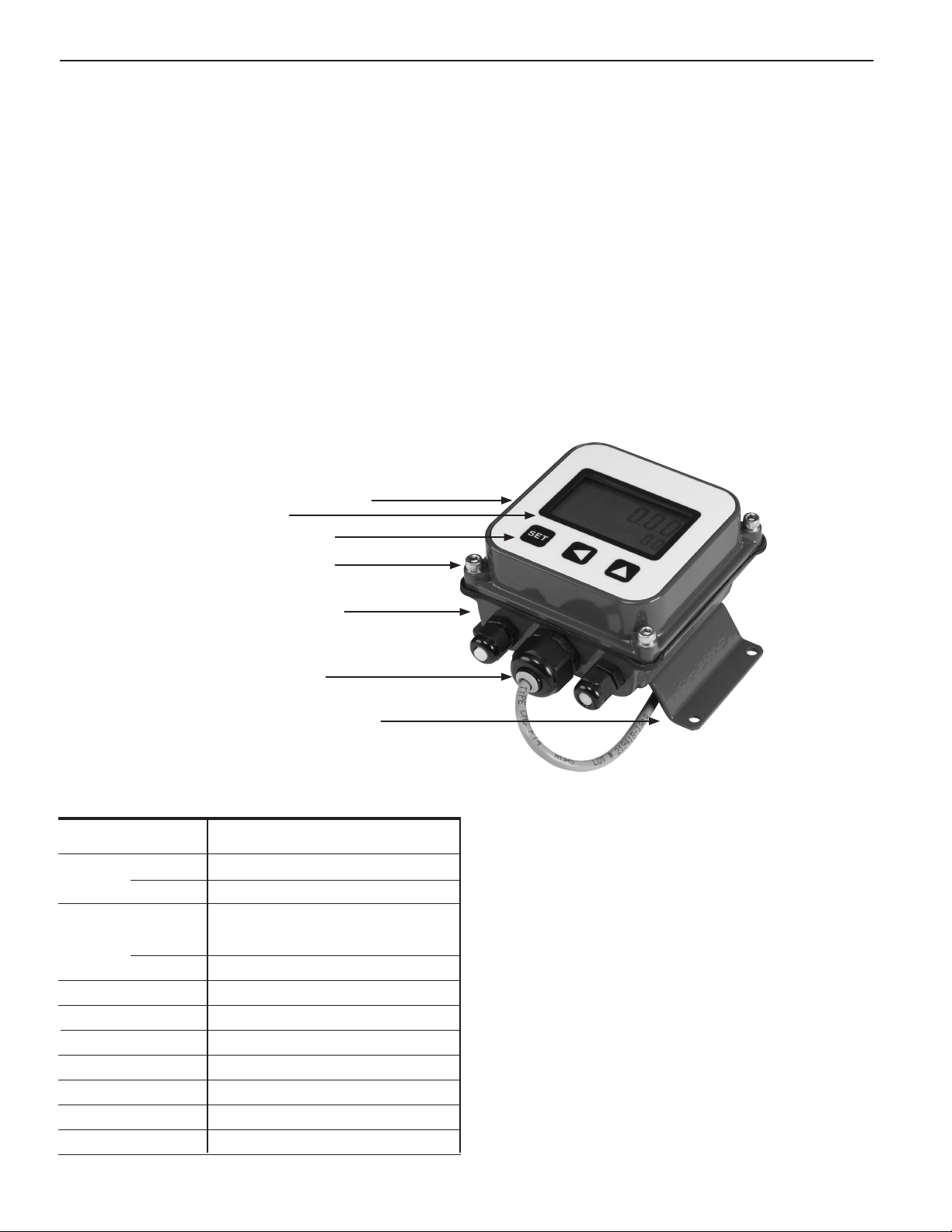
FEATURES
Electronics Module
Display
Setup Keys**
Cover Screws
The FMG980 Flow Computer can be ordered with a built-in
115 Vac/12-24 Vdc dual power supply for magmeters (-DPW).
Housings are rugged cast aluminum, potted and gasketed
for maximum environmental protection. A membrane keypad
allows settings to be changed without removing the cover.
(Password protection, a standard feature, can be used to
prevent settings from being changed.)
SPECIFICATIONS*
Power
Display Rate
Total
Output Pulse
Analog
Pulse Output Range
Input
Input Range
K-Factor Range
Flow Alarm Output Range
Temperature
Environmental
Lower Housing
Strain Relief
Wall-Mount Brackets
12-32 Vdc (for 4 mA DC min)
24-32 Vdc (for accuracy of 4-20 mA loop)
6-digit autorange, 1/2" character height
8-digit, 5/16" character height
0.1 second open collector pulse (scaled);
0-75 pulse/sec passthrough (unscaled);
High alarm or low alarm
4-20 mA loop (requires 24-32 Vdc)
0.1 - 9999999.9 units/pulse
Open collector/switch @ 5 Vdc
1.0 - 1,500 pulses/second
.001 - 99999.999
.01 - 999999.99
0˚ C - 70˚ C (32˚ - 158˚ F)
NEMA 4X
Page 8
Page 12
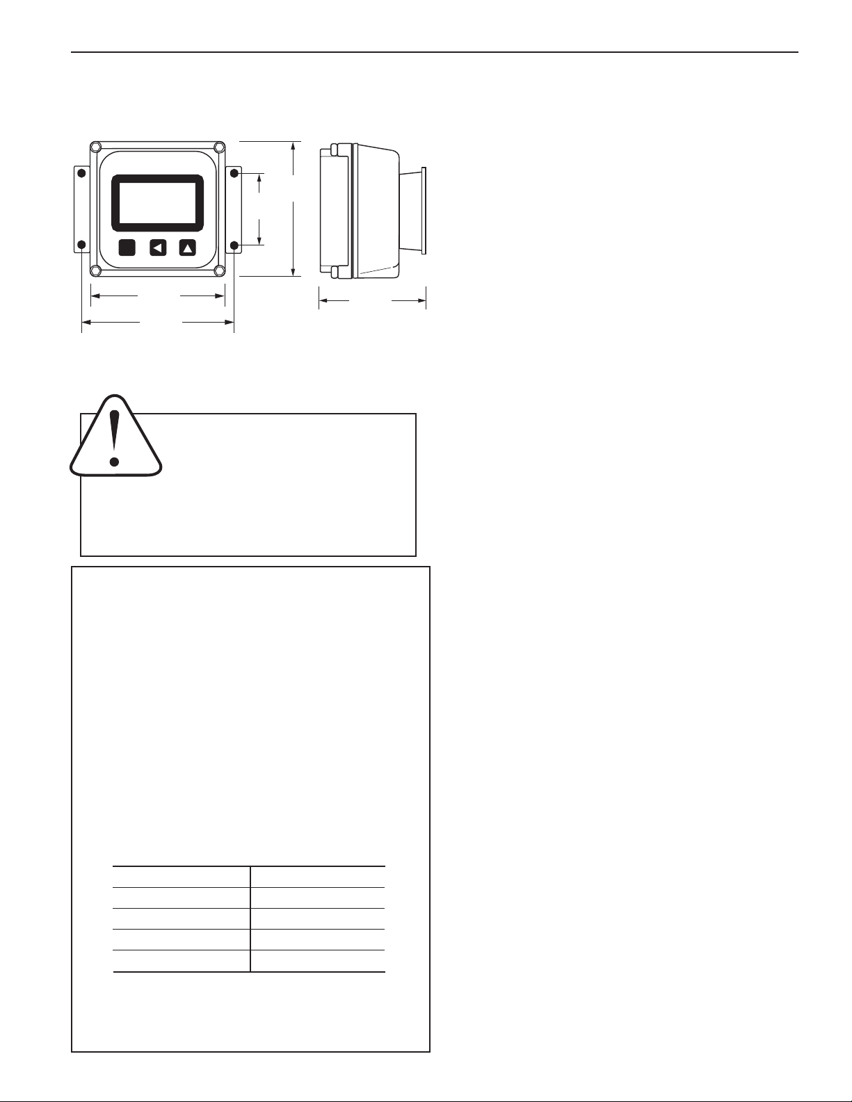
FMG980-M AND FMG980-W INSTALLATION and SETTINGS
Wall Mounting. To mount the FMG980-W on a wall, hold the
unit in the desired position, mark the holes in the mounting
feet, drill, and mount with screws.
10.5
2341678.9
SET
3.93"
4.52"
3.93"
2.06"
2.78"
CONNECTIONS
See Connections Diagram for FMG980-W, next page.
CAUTION! If output is being used to
control an external device, such as a
metering pump, do not connect the
device until programming is complet-
ed. If malfunction or incorrect programming of the output could cause personal injury
or property damage, separate safeguards must be
installed to prevent such injury or damage.
K-FACTOR
At a minimum, every FMG980 ow computer must be programmed with the “K-factor” (This is the number of pulses
that the meter produces per gallon of ow.) If you wish to
read in units other than gallons, see below.
The K-factor can be found on the model-serial label. The
line reading K = xxxx gives the desired number.
READING IN OTHER UNITS
Changing Volume Units. The default K-factor units are
pulses per gallon. To read your total in metric or other
units instead, the standard K-factor must be converted to
the desired volume units. For example, to read in pulses
per liter, the K-factor must be multiplied by the applicable
number shown below.
NOTE: Both rate & total will read in whatever units you choose.
To Convert K to: Multiply by:
Liters .26418
Cubic Meters 264.18
Fluid Ounces .0078
Cubic Feet 7.48
SETTINGS
Set K. Begin by pressing the SET key once. The prompt SET
K should appear on the display. The digit to the far right will
be blinking. Use the up arrow key to reach your desired value.
Then press the left arrow key to move to the next digit. Repeat
the process until the entire number is entered. (Note that the
decimal is fixed at three places. If you only have two decimal
places for your K-factor, enter a zero for the third digit.) Press
SET to advance.
Set P/Flow Alarm. At this screen you may select between
pulse output (P) or flow alarm (A) functions. If the pulse
output and flow alarm features are not being used, this step
can be skipped. The P (pulse output) setting does not affect
anything if it is not being used.
Set P is the default that appears on a new display. On a unit
that has been previously set up with flow alarm function, an A
will appear on this screen. To move between P and A screens,
firmly press all three keys for 5-10 seconds, then use the up
arrow to scroll through the three options: P, AL HI (high flow
alarm) and AL LO (low flow alarm).
Set P. From this screen, follow the same process as for Set K
to enter the desired pulse rate. This is the number of gallons
(or whatever units are programmed) between pulses. (Note:
Using the pulse output function disables the high and low
flow alarm functions.)
Set Flow Alarm. From the A screen, use the up arrow key to
choose either AL HI or AL LO and then press the SET key to
set the alarm rate. Use the up arrow and left arrow as above
to reach the desired digits. (Note: Using the flow alarm function disables the pulse output function.)
Set 20 mA. Press the SET key to advance to SET 20, to set
the flow rate, in volume units per time unit, at which 20 mA
is desired. Use the up arrow key to reach your desired value.
Then press the left arrow key to move to the next digit. Repeat
the process until the entire number is entered. The processor
will automatically scale the 4-20 mA loop accordingly, with
4 mA at zero flow.
Set Decimal Point. Press the SET key again for the D prompt.
Pressing the up arrow key switches among no decimal place,
one decimal place and two decimal places.
Set Time Unit. When the SET key is pressed again, a
blinking time unit appears. Press the up arrow key
to select SEC (seconds), MIN (minutes), HR (hours) or
DAY (days) (for example, gal/min, or gal/hr).
To return to normal operation after entering settings, press
SET again. When the unit is connected to an operating flow
sensor, the rate (larger digits) and total (smaller digits) indicator numbers should appear in the display.
Changing Time Units: To read your rate in liters per second (for example), convert the K-factor volume units as
shown above and change the time units to Seconds, using the Set Time Unit instructions at right.
Page 9
Page 13
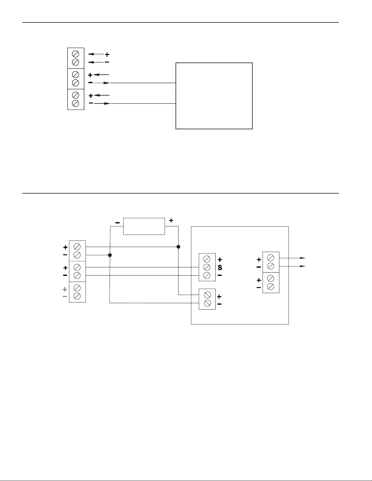
FMG980-M AND FMG980-W CONNECTIONS and OPERATION
+
_
+
_
+
_
+
_
S
+
_
+
_
+
+
_
_
+
_
+
_
COUNTER OR PLC
Power
Forward Output
Reverse Output
(Option-15 only)
FMG980
*See Dual FMG980 Diagram for an
example of bidirectional connections.
12 - 24 Vdc
Max. 6 mA, 30 Vdc
Max. 6 mA 30 Vdc
FMG980 DISPLAY AND PROPORTIONAL FEED
24 Vdc Power
COUNTER OR PLC DIGITAL
INPUT
FMG980
Power
Forward Output
Reverse Output
(Option-15)
FMG980 SERIES
*See Dual FMG980 Diagram for an
example of bidirectional connections.
Sensor
Input
Power
4-20mA
Pulse
Scaled
Pulse
Pass-Thru
To
Proportional
Feed
Metering
Pump
Page 10
Page 14
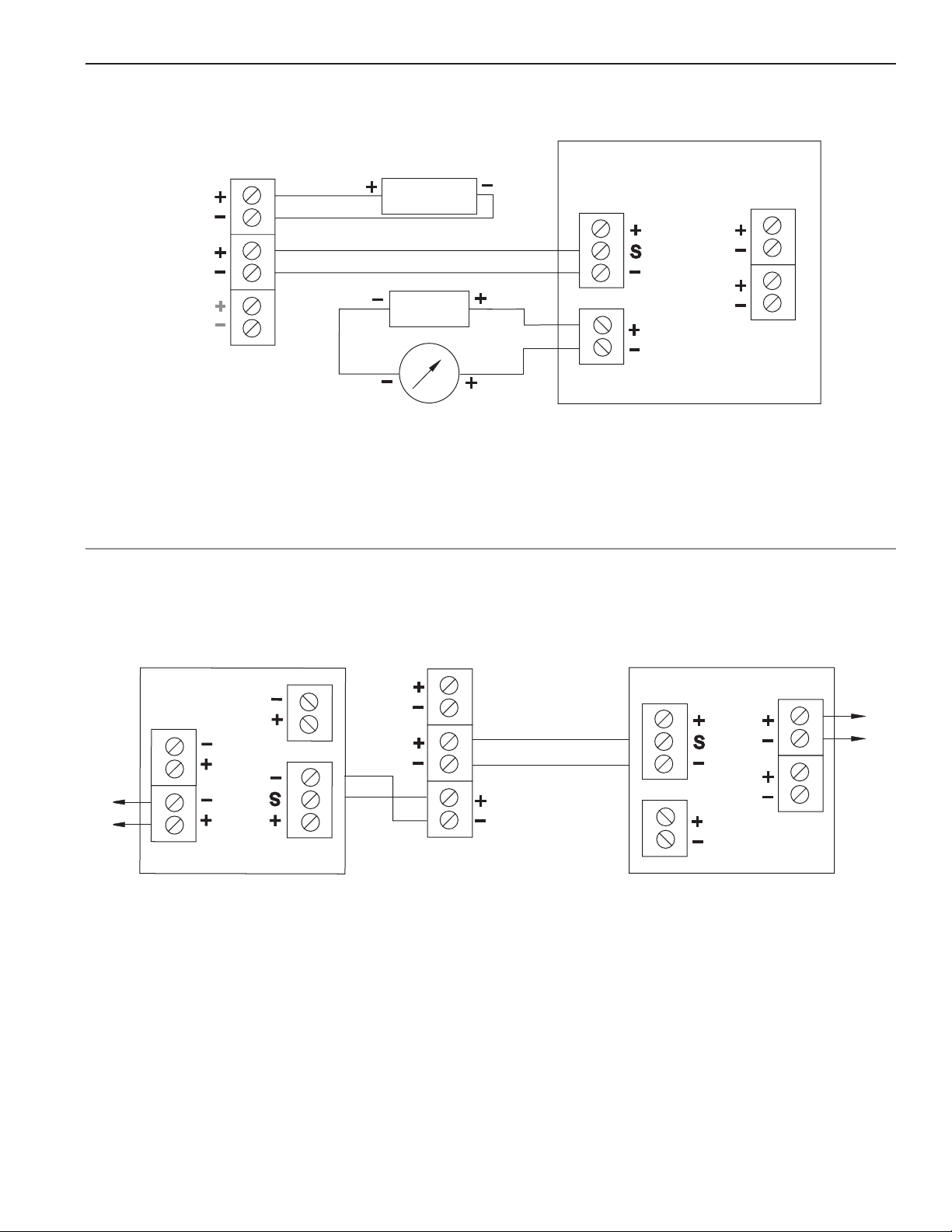
FMG980 CONNECTIONS and OPERATION
FMG980 DISPLAY AND 4-20 mA OUTPUT
FMG980
Power
Forward Output
Reverse Output
(Option-15 only)
*See Dual FMG980 Diagram for an
example of bidirectional connections.
+
_
+
_
FMG980 SERIES
DUAL FMG980 DISPLAYS
(Example of Bidirectional Connection)
24 Vdc
+
Power
_
24 Vdc
Power
_
4-20 mA Device
(e.g. pump, PLC)
_
Sensor
Input
+
S
Pulse
Scaled
+
_
_
+
+
+
_
+
Power
4-20mA
_
Pulse
Pass-Thru
FMG980
Power 4-20mA
Pulse
Pass-Thru
Pulse
Scaled
*Requires 12-24 Vdc power source.
Sensor
Input
*
Power
*
Forward Output
Reverse Output
(Option-15 only)
FMG980 SERIES
*
Sensor
Input
Power 4-20mA
FMG980
Pulse
Scaled
Pulse
Pass-Thru
Page 11
Page 15
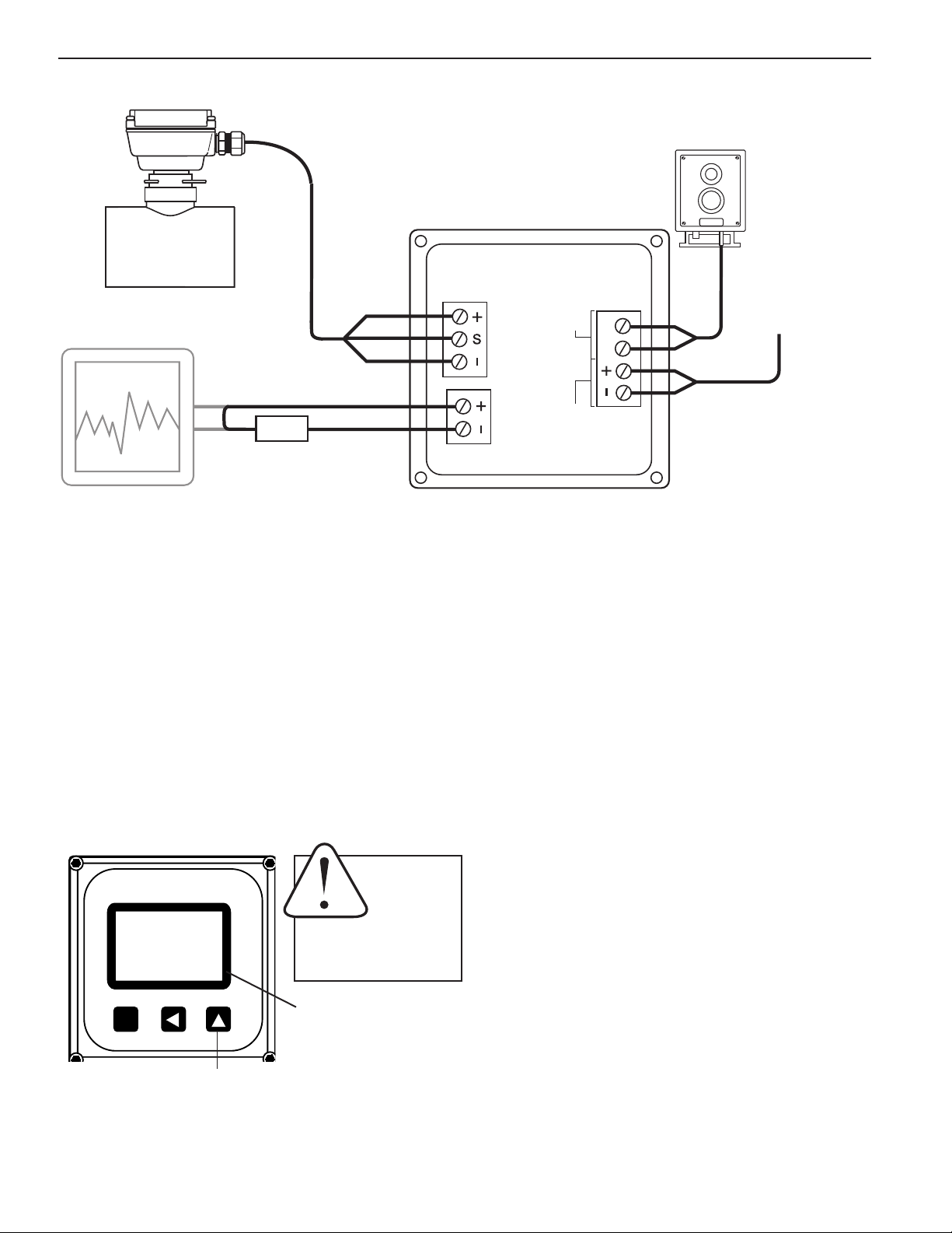
FMG980 CONNECTIONS and OPERATION
FMG980 CONNECTION DIAGRAM
FMG980 Series
Pulse Responsive
Metering Pump
FMG980-M/FMG 980-W
Red
White
SENSOR
INPUT
PULSE
SCALED
Black
4-20 mA
-
+
+
24-32 Vdc
-
POWER
PULSE
PASSTHRU
Loop Power,
Optional Chart
4-20 mA Output
Recorder or Other
4-20 mA Device
If the 4-20 mA current signal is not required, connect the power terminals to any 12-32 Vdc current source.
FMG980-M and FMG980-W OPERATION
Resettable/Non-Resettable Totalizer. Unless the unit has
been ordered with the non-reset option, a RESET prompt is
visible in the lower right corner above the up arrow key, when
the display is in use. Press the up arrow key at any time to reset
the totalizer to zero.
Operation of 4-20 mA Output. If the 4-20 mA output is in use
and is correctly connected, the signal should vary between 4 mA
and 20 mA in proportion to the ow, with the top ow rate set by
the user. At no time should the signal drop below 4 mA. A reading
between 0 and 4 mA indicates a fault of some type, typically in
the loop power supply or the connections (see Troubleshooting).
In the rare instance that the 4-20 signal uctuates excessively
1234.1
SET
123456.7
RESET
CAUTION: Do
not touch Up
Arrow button
unless you
intend to RE-
SET Total to Zero. TOTAL IS
NOT RECOVERABLE.
Indicates resettable totalizer
(“paints”) it may need to be damped by additional averaging.
Contact Omega for information on how to increase ltering.
Operation of the Pulse Output. If the pulse output is being used,
it should pulse for 0.1 second every time the set number of gallons has been totalized. If a pulse-responsive metering pump is
properly connected to this output, it should stroke periodically.
If this does not occur, see Troubleshooting.
This key resets total to zero
when in normal run mode.
To Other
Control
Page 12
Page 16

QUICK SETTINGS
PRESS DISPLAY
QUICK SETTINGS OVERVIEW
See following page for step-by-step instructions on changing these settings
Pass through all settings and return to original display to save settings.
SET
SET
SET
SET
0.00
MIN 209.8
START UP DISPLAY
00001.000
SET K
0000010.0
SET P
0001000.0
SET 20
RESET
d
209.8
Large digits display instantaneous flow rate (GPM).
Small digits display total flow (since last reset).
K is the number of pulses the flow sensor provides
for every gallon of flow.
P is the number of gallons per pulse desired on the
scalable pulse output. (Example: P=1 is one pulse
per gallon.) Skip without changing if you are not
using the pulse output.
20 is the 20 mA maximum analog output. Set the
flow rate you want to match maximum output.
Example: 250 gpm maximum expected flow, “set
20” to 250. The analog output will scale to 4 mA
at zero flow, 20 mA at 250 gpm*.
d is the decimal point. It toggles back and forth
with the . Set as many decimal places as
needed. For higher flows, no decimal allows
maximum number of whole digits.
Page 13
SET
MIN is the time base, for example, gallons per
MIN
*NOTE: Use the up arrow key to reach your desired digit. Then press the left arrow key to move
to the next digit. Repeat the process until the entire number is entered.
minute. Use the to select sec/min/hour/day.
Page 17

FMG980 TROUBLESHOOTING
Problem
Display blank No power to the unit Check for minimum 12 Vdc at power
terminals
Short in sensor circuit Disconnect sensor, see if display returns
(zero ow rate)
Display missing segments Damaged display module Contact Omega for return/replacement
Display reading meaningless Unit’s microcontroller crashed Disconnect and reconnect power. If problem
characters repeats, contact Omega for return/replacement
Display reads normally, Wrong K-factor or time base entered Enter correct K-factor from meter
Display reads normally, Wrong pulse output setting Use “Set P” to correct pulse output setting
incorrect pulse output
Polarity reversed on pulse output terminals Reverse leads
Display reads normally, but Wrong 20 mA setting Use “Set 20” to correct target top ow rate
no (or incorrect) 4-20 mA
output
Inadequate loop power supply voltage Check voltage (For 4-20 mA applications,
24-32 Vdc recommended)
Probable Cause Try...
Polarity incorrect in 4-20 mA loop circuit Compare to Connections diagram
Display reads zero when Flow sensor failed Consult Omega
there is ow
Break in ow sensor circuit Check for continuity with multimeter
Display reads ow rate when Long ow sensor wire, running parallel to Reroute wire or change to shielded wire
there is none power wires
Flow sensor malfunction Consult Omega
Flow “jitter” (oscillating slosh) reads as ow Consult Omega for “anti-jitter” setting
Page 14
Page 18

NOTES
Page 19

WARRANTY/DISCLAIMER
FOR NON-WARRANTY REPAIRS,
OMEGA ENGINEERING, INC. warrants this unit to be free of defects in materials and workmanship for a
period of 13 months f rom date of purchase. OMEGA’s WARRANTY adds an additional one (1) month
grace period to the normal one (1) year product warranty to cover handling and shipping time. This
ensures that OMEGA’s customers receive maximum coverage on each product.
If the unit malfunctions, it must be re t u r ned to the factory for evaluation. O M E G A’s Customer Serv i c e
D e p a rtm ent will issue an Authorized Return (AR) number immediately upon phone or written re q u e s t .
Upon examination by OMEGA, if the unit is found to be defective, it will be re p a i red or replaced at no
c h a rge. O M E G A ’s WARRANTY does not apply to defects resulting from any action of the purc h a s e r ,
including but not limited to mishandling, improper interfacing, operation outside of desi
i m p roper re p a i r, or unauthorized modification. This WARRANTY is VOID if the unit shows evidence of
having been tampered with or shows evidence of having been damaged as a result of excessive corro s i o n ;
or current, heat, moisture or vibration; improper specification; misapplication; misuse or other operating
conditions outside of OMEGA’s c o n t r ol. Components in which wear is not warranted, include but are not
limited to contact points, fuses, and triacs.
OMEGA is pleased to offer suggestions on the use of its various p roducts. Howev er,
OMEGA neither assumes responsibility for any omissions or e
damages that result from the use of its products in accordance with information provided by
OMEGA, either verbal or written. OMEGA warrants only that the parts manufactured by the
company will be as specified and free of defects. OMEGA MAKES NO OTHER WARRANTIES OR
R E P R E S E N T ATIONS OF ANY KIND WHATSOEVER, EXPRESSED OR IMPLIED, EXCEPT THAT OF
TITLE, AND ALL IMPLIED WARRANTIES INCLUDING ANY W
AND FITNESS FOR A PA R TICULAR PURPOSE ARE HEREBY DISCLAIMED. LIMITATION OF
L I A B I L I T Y: The remedies of purchaser set forth herein are exclusive, and the total liability of
OMEGA with respect to this ord e r , whether based on contract, warr a n t y, negligence,
indemnification, strict liability or otherwise, shall not exceed the purchase price of the
compon ent upon which l i abi lity is base d. In no event shall O MEGA be liab le for
co
nsequential, incidental or special damages.
CONDITIONS: Equipment sold by OMEGA is not intended to be used, nor shall it be used: (1) as a “Basic
Component” under 10 CFR 21 (NRC), used in or with any nuclear installation or activity; or (2) in medical
applications or used on humans. Should any Product(s) be used in or with any nuclear installation or
a c t i v i t y , medical application, used on humans, or misused in any way, OMEGA assumes no re s p o n s i b i l i t y
as set forth in our basic WA R R A N T Y/ D ISCLAIMER language, and, additionally, purchaser will indemnify
OMEGA and hold OMEGA h a rmless from any liability or damage whatsoever arising out of the use of the
P roduct(s) in such a manner.
rrors nor assumes liability for any
ARRANTY OF MERCHANTA B I L I T Y
gn limits,
RETURN REQUESTS/INQUIRIES
Direct all warranty and repair requests/inquiries to the OMEGA Customer Service Department. BEFORE
RETURNING ANY PRODUCT(S) TO OMEGA, PURCHASER MUST OBTAIN AN AUTHORIZED RETURN
(AR
) N U M B E R F R O M OMEGA’S C U S T O M E R SE RVICE D E PA R TM E N T (IN O R DER TO AV O I D
PROCESSING DELAYS). The assigned AR number should then be marked on the outside of the return
package and on any correspondence.
The purchaser is responsible for shipping charges, freight, insurance and proper packaging to prevent
breakage in transit.
WARRANTY RETURNS, please have the
FOR
following information available BEFORE
contacting OMEGA:
1 . P u r chase Order number under which the pro d u c t
was PURCHASED,
2. Model and serial number of the product under
warranty, and
3. Repair instructions and/or specific problems
relative to the product.
OMEGA’s policy is to make running changes, not model changes, whenever an improvement is possible. This affords
our customers the latest in technology and engineering.
OMEGA is a registered trademark of OMEGA ENGINEERING, INC.
© Copyright 2005 OMEGA ENGINEERING, INC. All rights reserved. This document may not be copied, photocopied,
reproduced, translated, or reduced to any electronic medium or machine-readable form, in whole or in part, without the
prior written consent of OMEGA ENGINEERING, INC.
for current repair charges. Have the following
information available BEFORE contacting OMEGA:
1. Purchase Order number to cover the COST
of the repair,
2. Model and serial number of the product, and
3. Repair instructions and/or specific problems
relative to the product.
consult OMEGA
Page 20

W h e r e Do I Find Eve rything I Need for
P r ocess Measurement and Control?
OME GA…Of Cours e !
Shop online at omega.com
T E M P E R A T U R E
Thermocouple, RTD & Thermistor Probes, Connectors, Panels & Assemblies
Wire: Thermocouple, RTD & Thermistor
Calibrators & Ice Point References
Recorders, Controllers & Process Monitors
Infrared Pyrometers
PRESSURE, STRAIN AND FO R C E
Transducers & Strain Gages
Load Cells & Pressure Gages
Displacement Transducers
Instrumentation & Accessories
F L OW / L E V E L
Rotameters, Gas Mass Flowmeters & Flow Computers
Air Velocity Indicators
Turbine/Paddlewheel Systems
Totalizers & Batch Controllers
p H / C O N D U C T I V I T Y
pH Electrodes, Testers & Accessories
Benchtop/Laboratory Meters
Controllers, Calibrators, Simulators & Pumps
Industrial pH & Conductivity Equi
pment
DATA AC Q U I S I T I O N
Data Acquisition & Engineering Software
Communications-Based Acquisition Systems
Plug-in Cards for Apple, IBM & Compatibles
Datalogging Systems
Recorders, Printers & Plotters
H E A T E R S
Heating Cable
Cartridge & Strip Heaters
Immersion & Band Heaters
Flexible Heaters
Laboratory Heaters
E N V I R O N M E N T A L
M O N I T ORING AND CONTRO L
Metering & Control Instrumentation
R e f r a c t o m e t e r s
Pumps & Tubing
Air, Soil & Water Monitors
Industrial Water & Wastewater Treatment
pH, Conductivity & Dissolved Oxygen Instruments
PL-OM-103045-031813
3/18/2013
M-5279/0313
 Loading...