

Page 1
User's Guide
Shop online at
omega.com
email: [email protected]
For latest product manuals:
omegamanual.Info
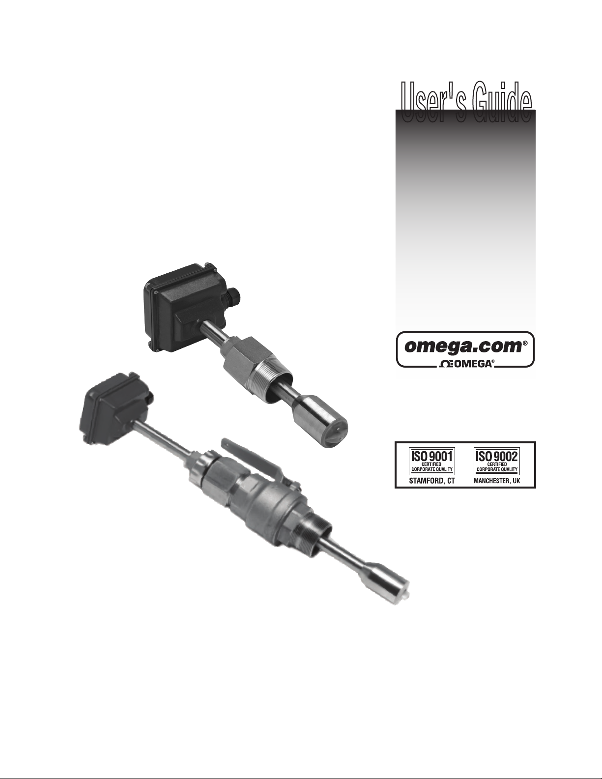
FMG900 SERIES
Insertion Magnetic Flow Meter
Page 2

OMEGAnet®Online Service Internet e-mail
It is the policy of OMEGA Engineering, Inc. to comply with all worldwide safety and EMC/EMI
regulations that apply. OMEGA is constantly pursuing certification of its products to the European New
Approach Directives. OMEGA will add the CE mark to every appropriate device upon certification.
omega.com i n f o @ o m e g a . c o m
Servicing North America:
U.S.A.: One Omega Drive, P.O. Box 4047
ISO 9001 Certified
Stamford, CT 06907-0047
TEL: (203) 359-1660 FAX: (203) 359-7700
e-mail: [email protected]
Canada: 976 Bergar
Laval (Quebec) H7L 5A1, Canada
TEL: (514) 856-6928 FAX: (514) 856-6886
e-mail: [email protected]
For immediate technical or application assistance:
U.S.A. and Canada: Sales Service: 1-800-826-6342 / 1-800-TC-OMEGA
Customer Service: 1-800-622-2378 / 1-800-622-BEST
Engineering Service: 1-800-872-9436 / 1-800-USA-WHEN
TELEX: 996404 EASYLINK: 62968934 CABLE: OMEGA
Mexico: En Espan˜ol: (001) 203-359-7803 e-mail: [email protected]
FAX: (001) 203-359-7807 [email protected]
®
®
®
Servicing Europe:
Benelux: Postbus 8034, 1180 LA Amstelveen, The Netherlands
TEL: +31 (0)20 3472121 FAX: +31 (0)20 6434643
Toll Free in Benelux: 0800 0993344
e-mail: [email protected]
Czech Republic: Frystatska 184, 733 01 Karviná, Czech Republic
France: 11, rue Jacques Cartier, 78280 Guyancourt, France
TEL: +33 (0)1 61 37 2900 FAX: +33 (0)1 30 57 5427
Toll Free in France: 0800 466 342
e-mail: [email protected]
Germany/Austria: Daimlerstrasse 26, D-75392 Deckenpfronn, Germany
TEL: +49 (0)7056 9398-0 FAX: +49 (0)7056 9398-29
Toll Free in Germany: 0800 639 7678
e-mail: [email protected]
United Kingdom: One Omega Drive, River Bend Technology Centre
ISO 9002 Certified
Northbank, Irlam, Manchester
M44 5BD United Kingdom
TEL: +44 (0)161 777 6611 FAX: +44 (0)161 777 6622
Toll Free in United Kingdom: 0800-488-488
e-mail: [email protected]
The information contained in this document is believed to be correct, but OMEGA accepts no liability for any
errors it contains, and reserves the right to alter specifications without notice.
WARNING: These products are not designed for use in, and should not be used for, human applications.
Page 3

TABLE OF CONTENTS
General Information
General Information, Features, Specications .................................................................................................Page 1
Installation
Piping, Distorted Flows, Immersion, Positioning the Meter ............................................................................Page 2
Fitting Installation, Meter Installation ............................................................................................................... Page 3
Proper Depth Setting ......................................................................................................................................... Page 4
Dimension “C”, Pipe Wall Thickness ................................................................................................................. Page 5
Straight Pipe Recommendations ...................................................................................................................... Page 6
Full Pipe Recommendations ..............................................................................................................................Page 7
Electrical Connections
General Electrical Guidelines, Power, Forward (and Reverse) Flow Output,
Grounding Guidelines, Grounding Diagram, Connection Diagram: Counter or PLC ...................................... Page 8
Operation & Maintenance
Zero Adjustment, Minimum Flow, Presence of Flow Indication, Filtering,
Electrode Coating, Calibration (“K-Factor”), Flow Rates in Gallons Per Minute ............................................. Page 9
K-Factor Chart
K-Factor for Various Pipe Sizes ......................................................................................................................... Page 10
Troubleshooting
Problems, Probable Causes and Things to Try ................................................................................................. Page 11
TABLES, DIAGRAMS & CHARTS
Features .............................................................................................................................................................. Page 1
Distorted Flows, Positioning the Meter ............................................................................................................. Page 2
Meter Installation, Sensor Removal .................................................................................................................. Page 3
Proper Depth Setting ......................................................................................................................................... Page 4
Dimension “C”, Pipe Wall Thickness ................................................................................................................. Page 5
Straight Pipe Recommendations ...................................................................................................................... Page 6
Full Pipe Recommendations ..............................................................................................................................Page 7
Grounding Diagram, Connection Diagrams: Counter or PLC........................................................................... Page 8
Flow Rates .......................................................................................................................................................... Page 9
K-factor Chart ..................................................................................................................................................... Page 10
Troubleshooting Problems, Probable Causes and Things to Try ..................................................................... Page 11
Page 4
GENERAL INFORMATION, FEATURES and SPECIFICATIONS
The complete lack of moving parts of the FMG900 Series insertion ow
sensor is the source of its reliability. Brass and stainless steel models
withstand a variety of temperature, pressure, and chemical conditions.
The FMG900 Series has no rotor to stop turning in dirty water and there
are no bearings to wear out.
A rapidly reversing magnetic eld is produced in the lower housing.
As the uid moves through this eld, a voltage is generated that is
measured and translated into a frequency signal proportional to ow
rate.
This square wave signal can be sent directly to a PLC or other control
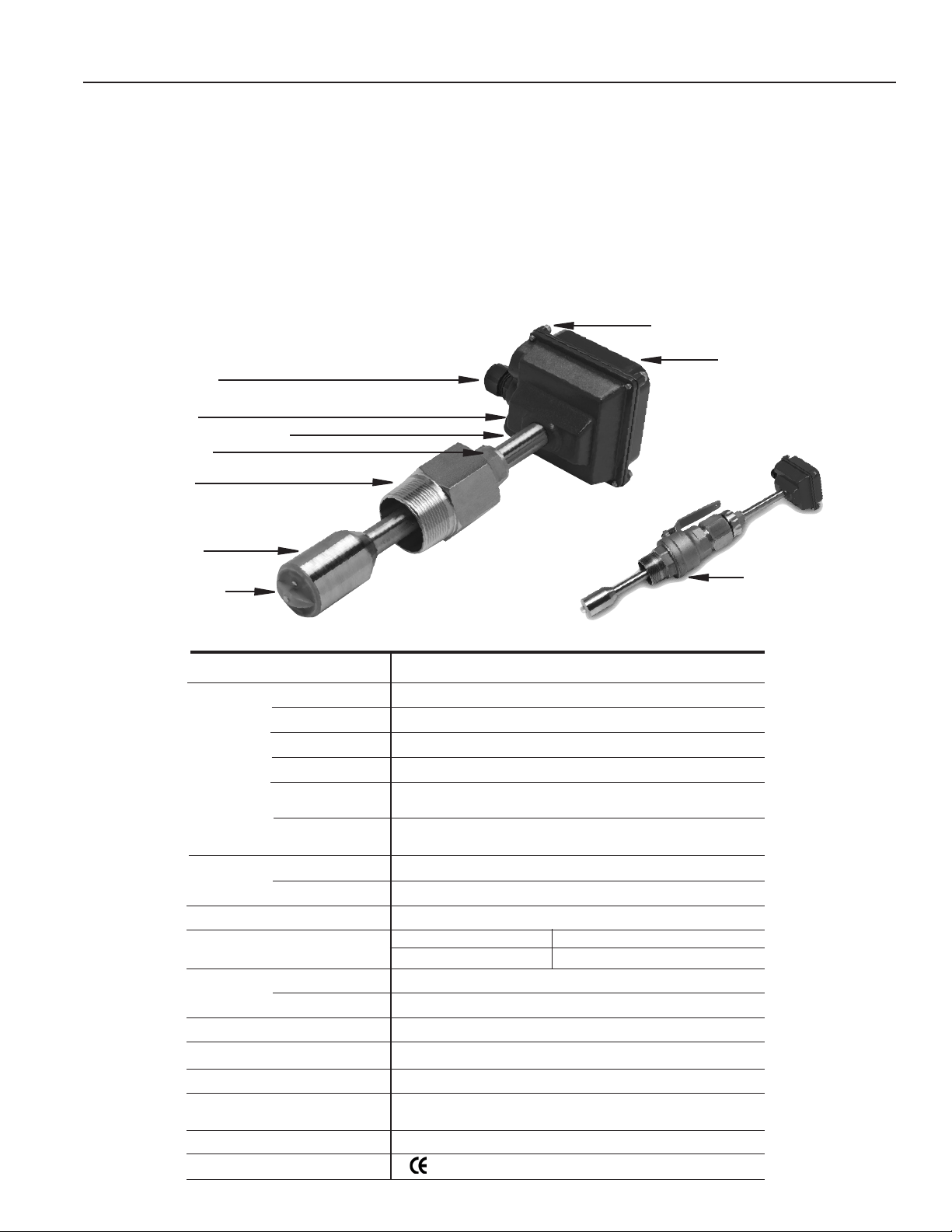
FEATURES
Cable Strain Relief
Lower Housing
Brass or 316 Stainless Shaft
Compression Nut
Adapter Fitting
1 1/2” Male NPT threads
Sensor Housing
Electrodes and Cap
or can be converted using any of the Omega family of indicators and
converters.
The adapter tting of the sensor is standard male NPT, and can be
directly threaded into ordinary saddles or threaded weld ttings. The
FMG905/906/907/908 include an isolation valve, allowing hot-tap
installation, or installation and removal under pressure; a bronze ball
valve is standard, with a 316 stainless steel valve option if needed.
Reverse ow output and immersibility are optional.
Housing Screw (connect ground to one)
Cover or Electronics Module
FMG901/902/903/904
FMG905/906/907/908
Valve assembly for
hot tap installation
SPECIFICATIONS*
Page 1
Pipe Sizes
Materials Shaft/Fitting
Electrodes
Electrode Cap
Housing
Valve Assembly
(115/215 Only)
O-Ring
(115/215 Only)
Power Full Power
Low Power
Flow Range
Fitting Size
Temperature Ambient
Fluid
Pressure
Minimum Conductivity
Calibration Accuracy
Output
Empty Pipe Detection
Regulatory
*Specications subject to change.
3” to 48” (up to 72” optional)
316 SS or Brass
Hastelloy
PVDF
Cast powder-coated aluminum
Bronze (stainless optional) with bronze ball valve
EPDM
12-25 Vdc, 250 mA
12-25 Vdc, 40 mA average with 250 mA peaks
0.28 to 20 ft/sec (0.08 - 6.09 m/sec)
FMG901/902/903/904 FMG905/906/907/908
1-1/2” Male NPT 2” Male NPT
0˚ to 160˚ F (-17˚ to 72˚ C)
32˚ to 200˚ F (0˚ to 93˚ C)
200 psi (13.8 bar)
20 microSiemens/cm
+/- 1% of full scale
Square wave pulse, opto isolated, 550 Hz @ 20 ft/sec
6 mA max, 30 Vdc forward ow standard; reverse ow optional
Software, defaults to zero ow
Mark
Page 5
INSTALLATION
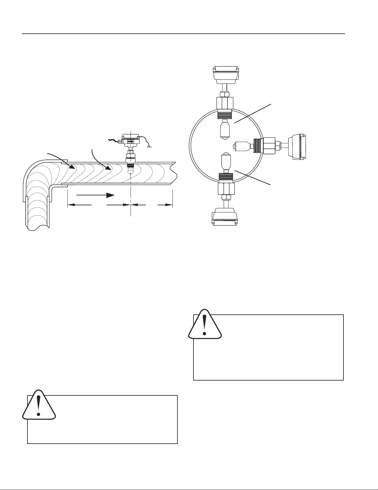
Piping. For best results, the sensor should be in-
stalled with at least ten diameters of straight pipe
upstream and ve downstream. Certain extreme situations
such as partially-opened valves are particularly difcult and
may require more straight diameters upstream (see page 6
for straight pipe recommendations).
DISTORTED FLOWS
Faster Flow
Causes Meter
Distorted
Flow Prole
To Read High
FLOW
10X
5X
POSITIONING THE METER
Fair
(Unacceptable position
if air is present)
Best
Position
Fair
(Unacceptable position if uid
contains sediment)
Immersion. The FMG900 Series sensors are not designed for
underwater operation. Even occasional immersion can cause
damage. If occasional immersion is possible, such as when a
vault oods, then the -40 option, (immersion) is recomended.
Chemical Injection or Fertigation. When any magmeter, by
any manufacturer, is used in a chemical injection application (including fertigation), the chemical line must be placed
downstream of the magmeter OR far enough upstream for
complete mixing to occur before the uid reaches the meter.
When unmixed chemical or fertilizer alternates with water
passing through the meter, the rapid changes in conductivity
may cause sudden spikes and drops in the meter’s reading,
resulting in inaccurate measurement. The magmeter will
restabilize, however, with a steady ow of uid of uniform
conductivity.
Caution: In chemical injection or fertigation applications, install chemical line
downstream of magmeter, or far enough
upstream to allow complete mixing of
uids before the meter.
Vertical ow in upward direction is the preferred installation
orientation, since it improves low-ow performance and avoids
problems with trapped air and sediment. Bottom, top, and
vertical pipe installations are all acceptable if required by
the piping layout.
Caution: These ow sensors are not rec-
ommended for installation downstream
of a boiler feedwater pump where instal-
lation fault may expose the ow sensor
to boiler pressure and temperature. Maximum
recommended temperature is 200°F.
Page 2
Page 6
INSTALLATION
FMG901/902/903/904 INSTALLATION
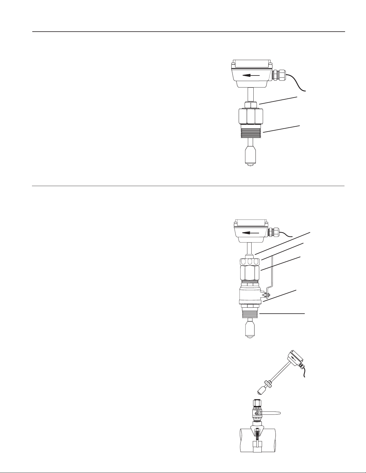
Fitting Installation. FMG901/902 sensors come with a 1-1/2” male
NPT pipe thread adapter tting. Any tting that provides the matching
NPT female thread may be used. Installation procedure compensates
for tting height differences. Cut a minimum 1-3/4” hole in the pipe. If
possible, measure the wall thickness and write it down for use in depth
setting. Then install the threaded tting (saddle, weldolet, etc.) on the
pipe.
Meter Installation. Loosen the compression nut so that the adapter
slides freely. Pull the meter fully upward and nger-tighten the compression nut. Using a thread sealant, install the adapter in the pipe tting.
Do not overtighten. Now loosen the compression nut, lower the meter
to the appropriate depth setting (see diagram and instructions that fol-
low). Be sure ow is in the direction of the arrow on the housing. Tighten
compression nut fully.
Compression nut
Adapter tting
with
standard NPT
threads
FMG905/906/907/908 INSTALLATION
‘Hot tap’ meters are designed so they can be installed and serviced
without depressurizing the pipe.
Fitting Installation. The FMG905/906/907/908 sensors have a 2”
NPT thread for compatibility with the 2” isolation valve. Any tting that
provides matching NPT female thread may be used. The installation
procedure compensates for differences in tting height.
If initial installation is performed on an unpressurized pipe, cut a
minimum 1-3/4” hole in the pipe. If possible, measure the wall thickness
and write it down for use in depth setting. Then install the threaded tting
(saddle, weldolet, etc.) on the pipe.
If it is necessary to do the initial installation under pressure, any standard
hot tap drilling machine with 2” NPT adapter, such as a Transmate or a
Mueller, can be used. Ordinarily, it is not necessary to use an installation
tool, due to the small diameter tube the meter can be installed by hand
at all but the highest pressures.
Compression nut
Locking collar
2” adapter removes
to mount hot-tap
machine
Full-port 2” ball
valve allows sensor
removal
Standard 2”
NPT threads
Meter Installation. Remove the sensor unit from the valve assembly.
Using a thread sealant, install the valve assembly on the pipe tting. If
the initial installation is a pressure (“hot”) tap, remove the 1-1/2” x 2”
adapter bushing at the back of the valve. Thread the tapping machine
on, open the valve, and tap using a minimum of 1-3/4” or maximum
1-7/8” cutter. After retracting the machine and closing the valve, reinstall
the ow sensor. When the sensor is secure, open the valve and adjust
depth setting (see diagram and instructions that follow). Be sure ow is
in the direction of the arrow on the housing. Tighten locking collar and
compression nut fully.
FMG905/906/907/908
Sensor Removal
Page 3
Page 7
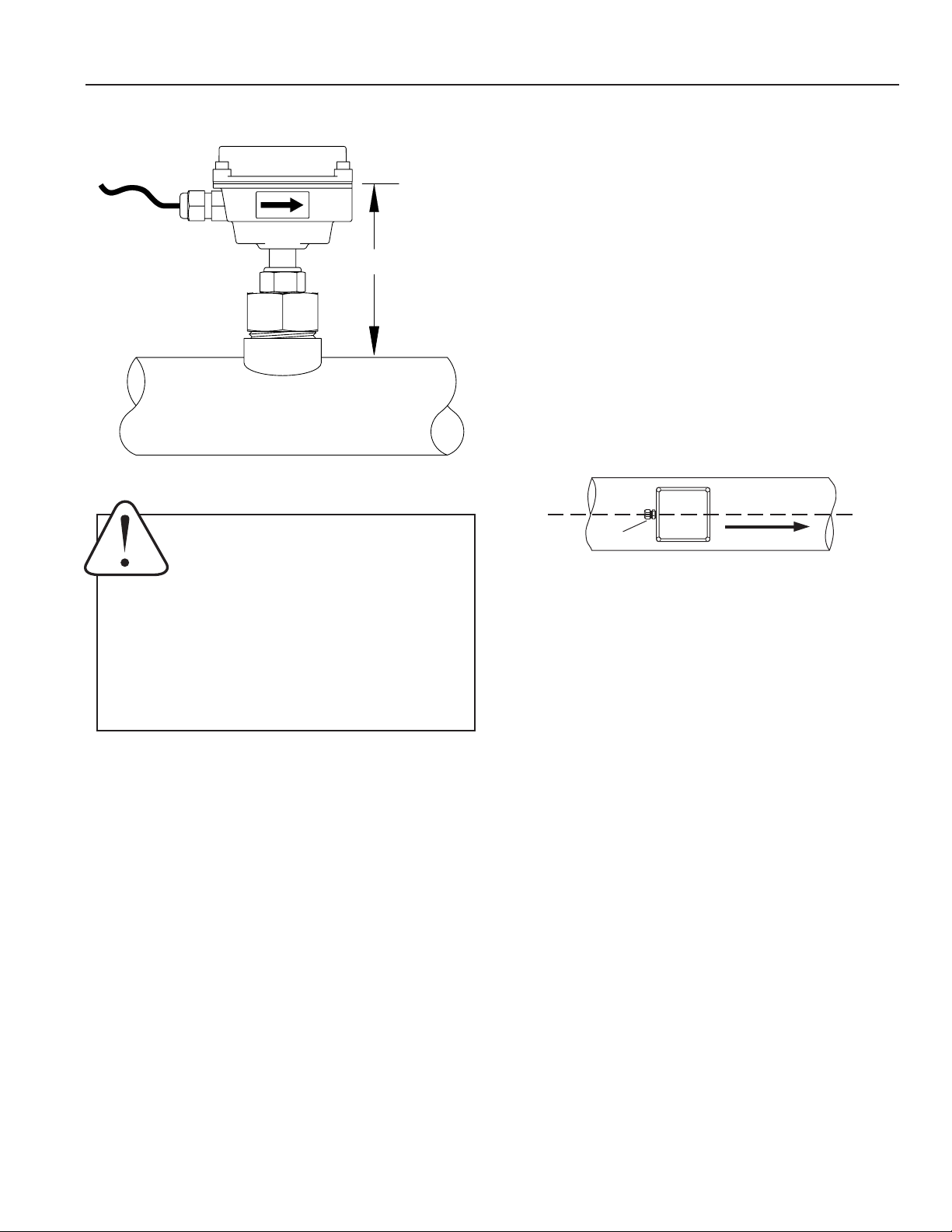
INSTALLATION
"D"
PROPER DEPTH SETTING
Depth Setting. It is important for accuracy that the sensor
be inserted to the correct depth into the pipe.
1. In Table 1, nd Dimension C for your sensor model
and pipe size. Subtract wall thickness of your pipe
(Table 2) to nd Dimension D.
2. Measuring from the outside of the pipe to the joint in
the housing, as shown in the diagram, adjust the
sensor to Dimension D and hand-tighten compression
nut.
3. Align the conduit housing with the centerline of the
pipe, as shown. Be sure the arrow on the housing
points in the direction of ow.
Caution! Never attempt to remove a ow
sensor when there is pressure in the pipe
unless it is specically designed for hot
tap installation and removal. Loosen the
compression nut slowly to release any trapped pres-
sure. If uid sprays out when removing the sensor,
stop turning and depressurize the pipe. Failure to
do so could result in the sensor being thrown from
the pipe, resulting in damage or serious injury.
strain
relief
4. Check Dimension D one more time.
5. Tighten the compression nut fully.
FLOW
Page 4
Page 8
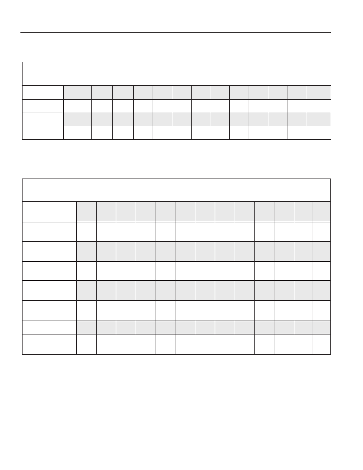
INSTALLATION
TABLE 1: DIMENSION “C”
NOMINAL PIPE SIZE
3” 4” 6” 8” 10” 12” 14” 16” 18” 20” 24” 30” 36”
FMG901/903
FMG902/904
FMG905/907
FMG906/908
10.04 9.93 9.69 9.46 9.22 8.99 8.75 8.52 8.28 8.05 7.58 6.87 6.17
15.04 14.93 14.69 14.46 14.22 13.99 13.75 13.52 13.28 13.05 12.58 11.87 11.17
17.04 16.93 16.69 16.46 16.22 15.99 15.75 15.52 15.28 15.05 14.58 13.87 13.17
21.04 20.93 20.69 20.46 20.22 19.99 19.75 19.52 19.28 19.05 18.58 17.87 17.17
TABLE 2: PIPE WALL THICKNESS
NOMINAL PIPE SIZE
3” 4” 6” 8” 10” 12” 14” 16” 18” 20” 24” 30” 36”
PVC/Steel
Sch. 40
PVC/Steel
Sch. 80
Stainless
Steel (10S)
0.216 0.237 0.280 0.322 0.365 0.406 0.438 0.500 0.562 0.593 0.687
0.300 0.337 0.432 0.500 0.593 0.687 0.750 0.843 0.937 1.031 1.218
0.120 0.120 0.134 0.148 0.165 0.180 0.188 0.188 0.188 0.218 0.250 0.312 0.312
Stainless
Steel (40S)
Copper Tubing
(Type L)
Copper Tubing
(Type K)
Brass Pipe
Duct. Iron
(Class 52)
0.216 0.237 0.280 0.322 0.365 0.375 0.375 0.375 0.375 0.375 0.375 0.375 0.375
0.090 0.110 0.140 0.200 0.250 0.280
0.109 0.134 0.192 0.271 0.338 0.405
0.219 0.250 0.250 0.312 0.365 0.375
0.280 0.290 0.310 0.330 0.350 0.370 0.390 0.400 0.410 0.420 0.440 0.470 0.530
Page 5
Page 9
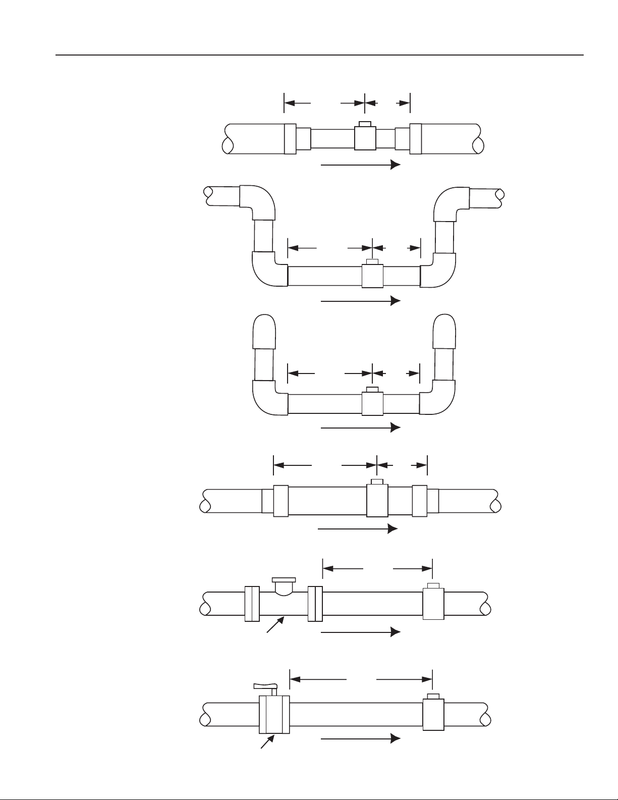
INSTALLATION
STRAIGHT PIPE RECOMMENDATIONS
(X = diameter)
Reduced Pipe
Two Elbows In Plane
Two Elbows, Out Of Plane
10X
20X
5X
5X10X
5X
Expanded Pipe
Spiral Flow
Swirling Flow
Propeller Meter
Partially Open
Buttery Valve
20X
5X
30X
50X
Page 6
Page 10
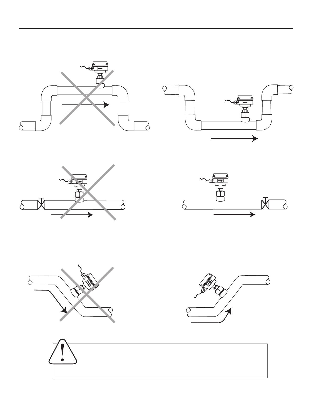
INSTALLATION
FULL PIPE RECOMMENDATIONS
Allows air pockets to form at sensor
Better InstallationPossible Problem
Ensures full pipe
Better InstallationPossible Problem
Post-valve cavitation can create air pocket Keeps pipe full at sensor
Better InstallationPossible Problem
Air can be trapped
Allows air to bleed off
Caution: These ow sensors are not recommended for installation down-
stream of a boiler feedwater pump where installation fault may expose the
ow sensor to boiler pressure and temperature. Maximum recommended
temperature is 200°F.
Page 7
Page 11
ELECTRICAL CONNECTIONS
+
_
+
_
+
_
GENERAL ELECTRICAL GUIDELINES
• Whenever possible, avoid running control cables in the
same conduit with AC power.
• Use shielded cable, with one end grounded.
• Avoid routing ow sensor cables in close proximity to a
variable frequency drive.
• Recommended power and output wiring is shielded
18-22 AWG control cable.
• Recommended voltage is 12-24 Vdc.
Note: unregulated power supplies can vary from name plate voltage by a considerable amount. When in
doubt, use a regulated power supply.
Power: A 12 - 24 Vdc power supply capable of at least 250
mA current output is needed.
Forward (and Reverse) Flow Output: This open-collector
isolated output does not supply power. It functions like a
polarity-sensitive switch closure. This pulse is generated in
the forward ow direction on the standard unit. (Reverse ow
output is available as an option). Note: This output is limited
to 6 mA at 30 Vdc maximum.
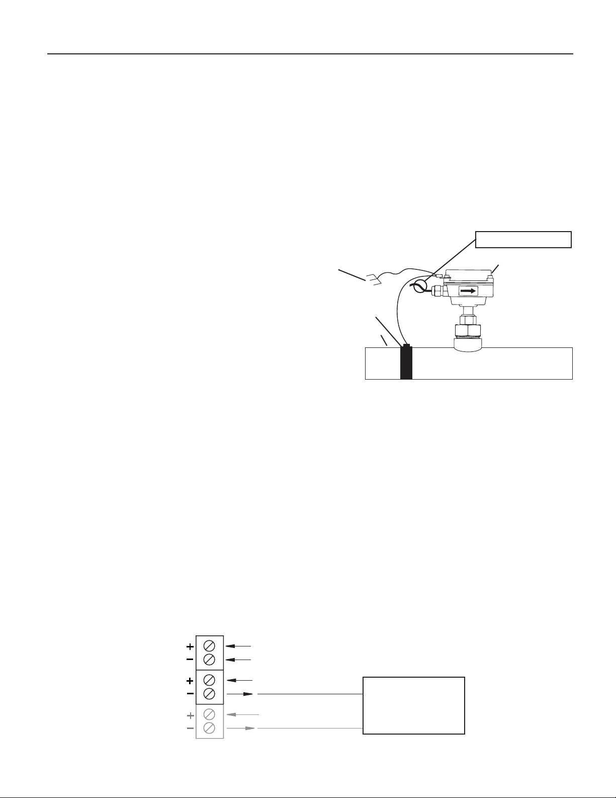
GROUNDING GUIDELINES
For best results, use a good quality earth ground, such as
metallic water piping, or a stake driven into the ground, to
ensure a good connection to earth ground and good noise
suppression.
If the ow sensor is installed in metallic piping, for optimum
connection clamp wire to the piping a short distance to one
side of the ow sensor using a hose type clamp. Connect the
wire to the earth ground and to one of the housing screws. (For
non-metallic piping, this step is not needed.)
PLACE FERRITE BEAD HERE
Earth
Ground
Hose Clamp
Metallic Pipe
FMG900 Series meters are usually unaffected by moderate
levels of electrical noise. In some applications performance
may be improved by taking the following steps:
Housing Screw
CONNECTION DIAGRAM
Forward Output
Reverse Output
(Option-15 only)
Power
• Use shielded twisted pair cable (Belden 8723 or
equivalent above ground or Alpha 35482 or
equivalent burial).
• Clamp a ferrite bead (Steward 28A2029-OAO or
equivalent) on meter signal/power wire within 3/4”
of the meter strain relief (tape or tie wrap in place if
necessary). See diagram above.
• IMPORTANT - Connect the cable shield ground wire
to ground, ONLY at power supply end of cable.
12 - 24 Vdc
Max. 6 mA, 30 Vdc
Max. 6 mA 30 Vdc
COUNTER OR PLC
DIGITAL INPUT
FMG900 SERIES
Page 8
Page 12
OPERATION & MAINTENANCE
30Vdc
Max. 6mA
-+-
+
12-24Vdc
345621
Power
Forward
Output
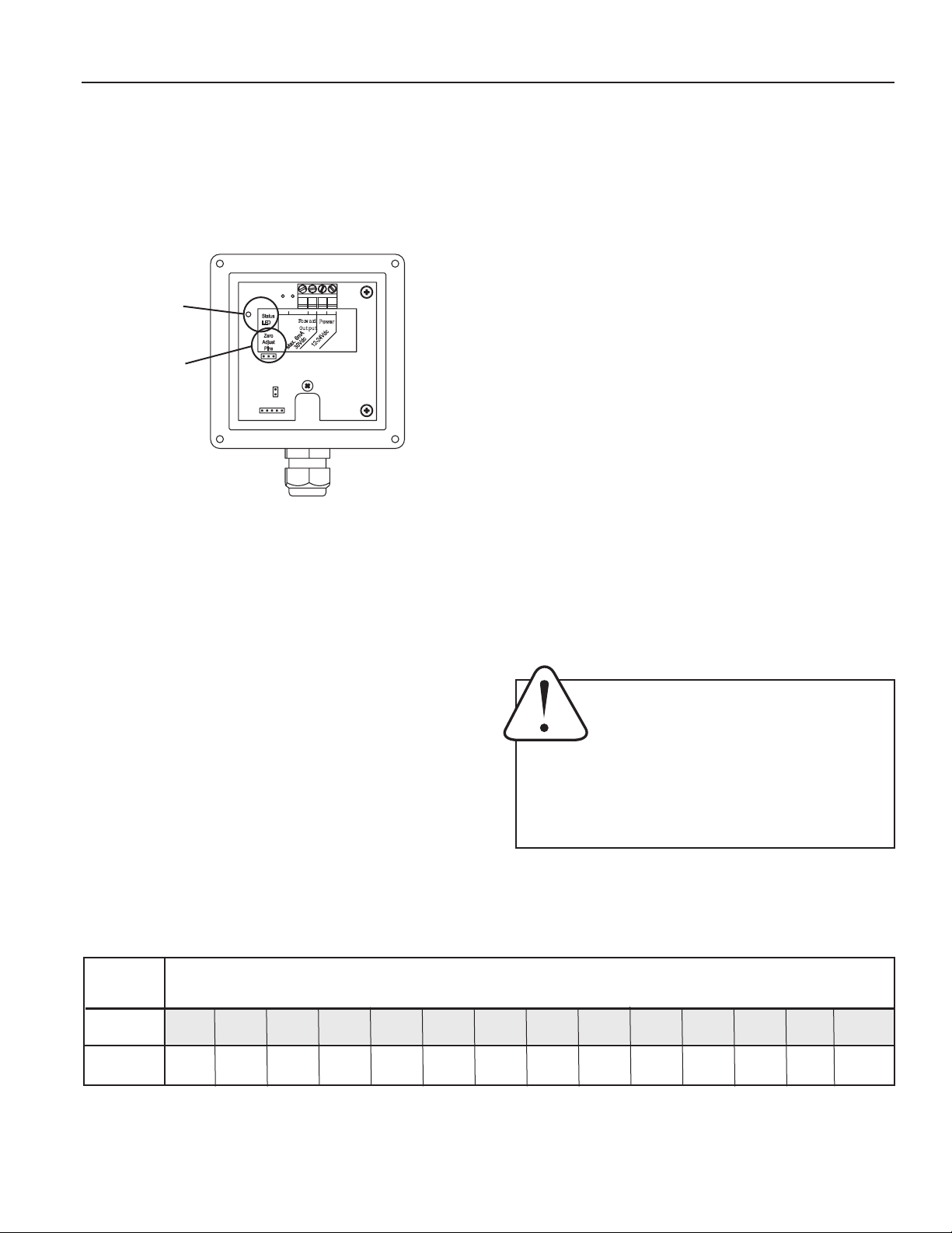
Status
LED
Zero
Adjust
Pins
Zero Adjustment. When the FMG900 Series meter is powered
up and there is no ow, there should be no output pulses (or,
if connected to a display or controller, ow rate should read
“0”). If there are pulses, it may be necessary to adjust the
ow meter under no-ow conditions after it has been installed.
This should only be done if the indicated ow is low, near
the lower cutoff.
Status
LED
Zero
Adjust
Pins
To perform the adjustment, after determining that there is a
full pipe with no ow, short between the two pins marked “Zero
Adjust”. A red LED light will come on for approximately 50 seconds and then go out. The zero adjustment is completed.
Minimum Flow. As with any other ow sensor, there is a rate
below which the FMG900 Series sensor cannot read. Check
the table below for the minimum ow rate detectable by the
sensor for a given pipe size. Minimum ow is 0.28 ft/sec.
Presence of Flow Indication. To assist in troubleshooting,
the “Status LED” has two blinking modes in normal operation.
When there is no flow detectable by the meter (below
minimum threshold) the LED blinks every 8.0 seconds. When
there is detectable ow, the same indicator blinks every 3.0
seconds (Pulses are being output when indicator is blinking
every 3 seconds).
Filtering. The software of the FMG900 Series lters out
electrical noise and averages sudden variations in the ow
to smooth the output. It takes a matter of seconds for the
ow sensor to get up to full output when it is powered up or
when ow begins.
Electrode Coating. Grease or other adhering, non-conductive
materials can stop ow detection if the electrodes become
heavily coated. To clean the electrodes, remove the sensor
from the pipe and gently scrub the electrodes (three silver
bumps) on the reading face of the ow sensor. A mild soap
(dishwashing liquid for example) can be used to aid the
cleaning process.
Calibration (“K-Factor”). In order to properly process pulses
from the ow sensor, a number must be entered into the control to which the sensor is connected. This number, called the
K-factor, is the number of pulses the sensor puts out per unit
of uid passing through the pipe. Find the K-factor for your
pipe size and type in the table on the following page and
enter it into your display or controller. These numbers are
based on extensive testing, which has shown close agreement
among different FMG900 sensors in the same installation.
Typically, most K-factor error can be attributed to installation
variables, such as depth setting and tting conguration.
CAUTION! Never attempt to remove a ow
sensor when there is pressure in the pipe
unless it is specically designed for hot tap
installation and removal. Loosen the com-
pression nut slowly to release any trapped pressure. If
uid sprays out when removing the sensor, stop turning
and depressurize the pipe. Failure to do so could result
in the sensor being thrown from the pipe, resulting in
damage or serious injury.
FLOW RATES (IN GALLONS PER MINUTE)
NOMINAL PIPE SIZE
3” 4” 6” 8” 10” 12” 14” 16” 18” 20” 24” 30” 36” 48”
6 11 25 44 69 99 134 175 222 274 395 617 888 1580
440 783 1,762 3,133 4,895 7,050 9,596 12,533 15,863 19,584 28,200 44,064 63,452 112,804
Feet Per
Second
Min 0.2
Max 20.0
Page 9
Page 13

K-FACTOR CHART
FMG900 SERIES K-FACTORS FOR VARIOUS PIPE SIZES
NOMINAL PIPE SIZE
3” 4” 6” 8” 10” 12” 14” 16” 18” 20” 24” 30” 36”
PVC/Steel
Sch. 40
70.397 40.985 18.130 10.497 6.674 4.709 3.900 2.989 2.364 1.904 1.319
PVC/Steel
Sch. 80
Stainless
Steel (10S)
Stainless
Steel (40S)
Copper Tubing
(Type L)
Copper Tubing
78.748 45.360 20.084 11.495 7.322 5.184 4.297 3.281 2.588 2.094 1.451
62.385 36.626 16.510 9.642 6.173 4.373 3.620 2.756 2.169 1.762 1.223 0.784 0.576
70.397 40.985 18.130 10.497 6.674 4.661 3.827 2.893 2.263 1.819 1.249 0.791 0.580
76.371 43.552 19.513 11.201 7.230 5.016
78.371 44.638 20.223 11.622 7.500 5.239
(Type K)
Brass Pipe
Duct. Iron
(Class 52)
70.672 41.517 17.778 10.445 6.674 4.661
57.376 37.320 16.915 9.503 6.197 4.325 3.189 2.443 1.931 1.565 1.088 0.747 0.520
Note: These K-Factors are calculated using actual pipe diameters and wall thicknesses for each pipe type. They are
based on the most current testing at the time of printing.
Page 10
Page 14

TROUBLESHOOTING
Problem
No pulse output
Output pulses incorrect
Probable Cause Try...
Unit not grounded
Below minimum ow cutoff
Flow reversed
Output connections reversed
Pipe not full
Excessive electrical noise
No power
Power reversed
Fluid conductivity <20 microSiemens/cm
Missing or incorrect ground wire
Incorrect depth setting
Connect to earth ground
Check the Presence of Flow LED (see p. 12)
Note ow direction arrow,
reverse direction to meter
Change output connections
Check plumbing
Check for proper electrical wiring
Check for power across power input terminals
Reverse connections
Select another ow meter
Check for proper ground
Check depth setting from
Dimension “C” table (page 4)
Jumpy reading
Fluid conductivity <20 microSiemens/cm
Empty pipe
Not enough straight pipe
Excessive electrical noise
Rapidly changing conductivity (in chemical
injection or fertigation applications)
Select another ow meter
Check for full pipe or install meter in the vertical
position
Check for air pockets or turbulence. Refer to
installation, page 6
Check for proper electrical wiring
Install chemical injection line downstream of
magmeter (or far enough upstream to allow
complete mixing of uids before meter)
Page 11
Page 15

WARRANTY/DISCLAIMER
FOR NON-WARRANTY REPAIRS,
OMEGA ENGINEERING, INC. warrants this unit to be free of defects in materials and workmanship for a
period of 13 months f rom date of purchase. OMEGA’s WARRANTY adds an additional one (1) month
grace period to the normal one (1) year product warranty to cover handling and shipping time. This
ensures that OMEGA’s customers receive maximum coverage on each product.
If the unit malfunctions, it must be re t u rned to the factory for evaluation. O M E G A’s Customer Serv i c e
D e p a rtm ent will issue an Authorized Return (AR) number immediately upon phone or written re q u e s t .
Upon examination by OMEGA, if the unit is found to be defective, it will be re p a i red or replaced at no
c h a rge. O M E G A’s WARRANTY does not apply to defects resulting from any action of the purc h a s e r ,
including but not limited to mishandling, improper interfacing, operation outside of desi
i m p roper re p a i r, or unauthorized modification. This WARRANTY is VOID if the unit shows evidence of
having been tampered with or shows evidence of having been damaged as a result of excessive corro s i o n ;
or current, heat, moisture or vibration; improper specification; misapplication; misuse or other operating
conditions outside of OMEGA’s c o n t r ol. Components in which wear is not warranted, include but are not
limited to contact points, fuses, and triacs.
OMEGA is pleased to offer suggestions on the use of its various products. However,
OMEGA neither assumes responsibility for any omissions or e
damages that result from the use of its products in accordance with information provided by
OMEGA, either verbal or written. OMEGA warrants only that the parts manufactured by the
company will be as specified and free of defects. OMEGA MAKES NO OTHER WARRANTIES OR
R E P R E S E N T ATIONS OF ANY KIND WHATSOEVER, EXPRESSED OR IMPLIED, EXCEPT THAT OF
TITLE, AND ALL IMPLIED WARRANTIES INCLUDING ANY W
AND FITNESS FOR A PA R TICULAR PURPOSE ARE HEREBY DISCLAIMED. LIMITATION OF
L I A B I L I T Y: The remedies of purchaser set forth herein are exclusive, and the total liability of
OMEGA with respect to this ord e r, whether based on contract, warr a n t y, negligence,
indemnification, strict liability or otherwise, shall not exceed the purchase price of the
compone nt upo n which li ability is b ased. I n no event shall OMEGA be liabl e for
co
nsequential, incidental or special damages.
CONDITIONS: Equipment sold by OMEGA is not intended to be used, nor shall it be used: (1) as a “Basic
Component” under 10 CFR 21 (NRC), used in or with any nuclear installation or activity; or (2) in medical
applications or used on humans. Should any Product(s) be used in or with any nuclear installation or
a c t i v i t y , medical application, used on humans, or misused in any way, OMEGA assumes no re s p o n s i b i l i t y
as set forth in our basic WA R R A N T Y/ D ISCLAIMER language, and, additionally, purchaser will indemnify
OMEGA and hold OMEGA h a rmless from any liability or damage whatsoever arising out of the use of the
P roduct(s) in such a manner.
rrors nor assumes liability for any
ARRANTY OF MERCHANTA B I L I T Y
gn limits,
RETURN REQUESTS/INQUIRIES
Direct all warranty and repair requests/inquiries to the OMEGA Customer Service Department. BEFORE
RETURNING ANY PRODUCT(S) TO OMEGA, PURCHASER MUST OBTAIN AN AUTHORIZED RETURN
(AR
) NUMB ER FROM OMEG A’S CUSTO MER SERVICE DEPA R TMENT (IN O R DER TO AV O I D
PROCESSING DELAYS). The assigned AR number should then be marked on the outside of the return
package and on any correspondence.
The purchaser is responsible for shipping charges, freight, insurance and proper packaging to prevent
breakage in transit.
WARRANTY RETURNS, please have the
FOR
following information available BEFORE
contacting OMEGA:
1 . P u r chase Order number under which the pro d u c t
was PURCHASED,
2. Model and serial number of the product under
warranty, and
3. Repair instructions and/or specific problems
relative to the product.
OMEGA’s policy is to make running changes, not model changes, whenever an improvement is possible. This affords
our customers the latest in technology and engineering.
OMEGA is a registered trademark of OMEGA ENGINEERING, INC.
© Copyright 2005 OMEGA ENGINEERING, INC. All rights reserved. This document may not be copied, photocopied,
reproduced, translated, or reduced to any electronic medium or machine-readable form, in whole or in part, without the
prior written consent of OMEGA ENGINEERING, INC.
for current repair charges. Have the following
information available BEFORE contacting OMEGA:
1. Purchase Order number to cover the COST
of the repair,
2. Model and serial number of the product, and
3. Repair instructions and/or specific problems
relative to the product.
consult OMEGA
Page 16

W h e r e Do I Find Eve rything I Need for
P r ocess Measurement and Control?
OME GA…Of Cours e !
Shop online at omega.com
T E M P E R A T U R E
Thermocouple, RTD & Thermistor Probes, Connectors, Panels & Assemblies
Wire: Thermocouple, RTD & Thermistor
Calibrators & Ice Point References
Recorders, Controllers & Process Monitors
Infrared Pyrometers
PRESSURE, STRAIN AND FO R C E
Transducers & Strain Gages
Load Cells & Pressure Gages
Displacement Transducers
Instrumentation & Accessories
F L OW / L E V E L
Rotameters, Gas Mass Flowmeters & Flow Computers
Air Velocity Indicators
Turbine/Paddlewheel Systems
Totalizers & Batch Controllers
p H / C O N D U C T I V I T Y
pH Electrodes, Testers & Accessories
Benchtop/Laboratory Meters
Controllers, Calibrators, Simulators & Pumps
Industrial pH & Conductivity Equi
pment
DATA AC Q U I S I T I O N
Data Acquisition & Engineering Software
Communications-Based Acquisition Systems
Plug-in Cards for Apple, IBM & Compatibles
Datalogging Systems
Recorders, Printers & Plotters
H E A T E R S
Heating Cable
Cartridge & Strip Heaters
Immersion & Band Heaters
Flexible Heaters
Laboratory Heaters
E N V I R O N M E N T A L
M O N I T ORING AND CONTRO L
Metering & Control Instrumentation
R e f r a c t o m e t e r s
Pumps & Tubing
Air, Soil & Water Monitors
Industrial Water & Wastewater Treatment
pH, Conductivity & Dissolved Oxygen Instruments
PL-OM-65200313-050511
05/05/11
M-4598/0511
 Loading...