

Page 1
User’s Guide
Shop online at
omega.com
e-mail: [email protected]
For latest product manuals:
www.omegamanual.info
SM
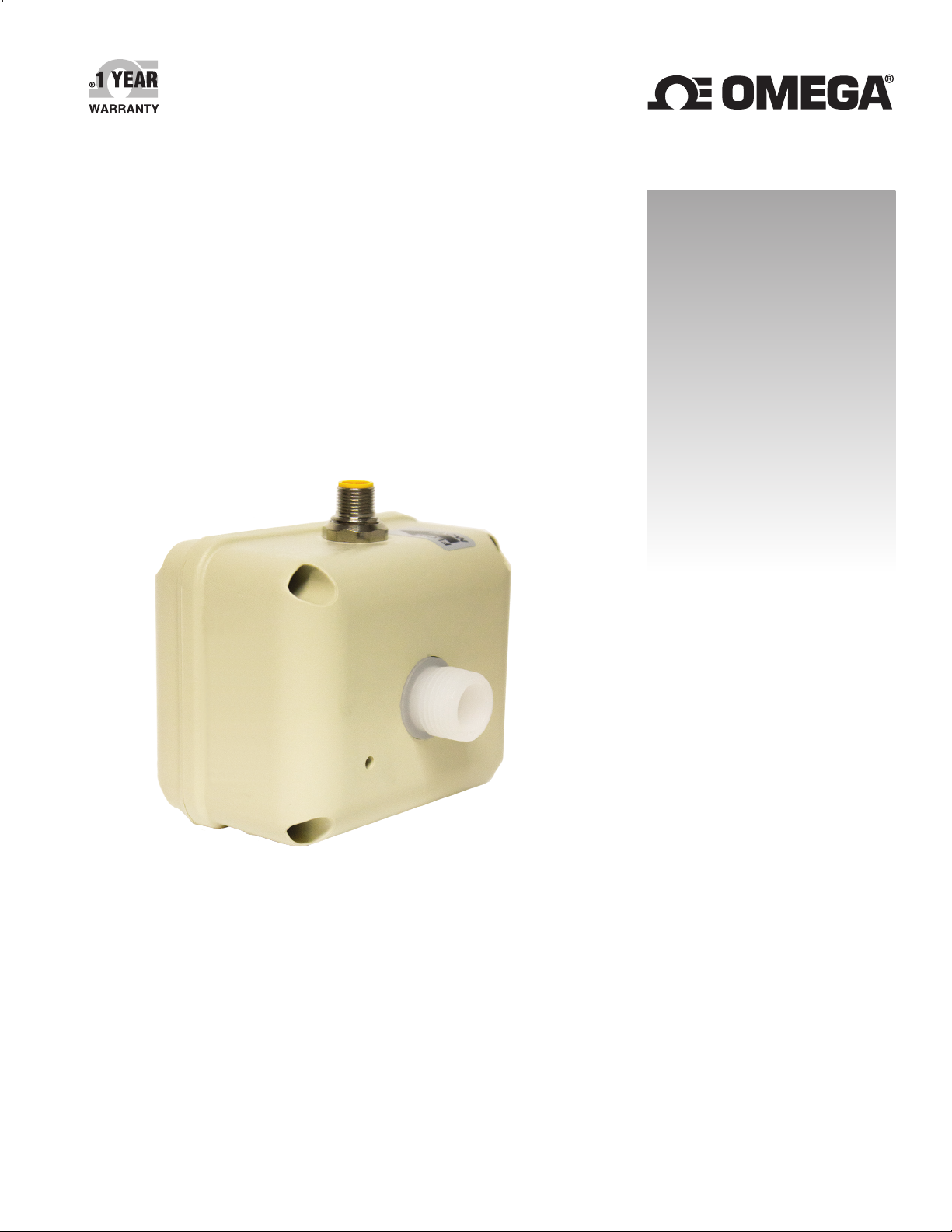
FMG80A SERIES
Low-Flow Magmeter
Page 2

omega.com [email protected]
Servicing North America:
U.S.A. Omega Engineering, Inc.
Headquarters: Toll-Free: 1-800-826-6342 (USA & Canada only)
Customer Service: 1-800-622-2378 (USA & Canada only)
Engineering Service: 1-800-872-9436 (USA & Canada only)
Tel: (203) 359-1660 Fax: (203) 359-7700
e-mail: [email protected]
For Other Locations Visit omega.com/worldwide
The information contained in this document is believed to be correct, but OMEGA accepts no liability for any errors it contains, and reserves
the right to alter specifications without notice.
Page 3

TABLE OF CONTENTS
FMG80A-SERIES INSTRUCTIONS
General Information
General Information ...............................................................................................................................................................Page 4
Features .....................................................................................................................................................................................Page 4
Specications ............................................................................................................................................................................Page 5
Dimensions ................................................................................................................................................................................Page 6
Pressure Drop Curve ..............................................................................................................................................................Page 6
Installation
Positioning .................................................................................................................................................................................Page 7
Mounting ....................................................................................................................................................................................Page 7
Piping ...........................................................................................................................................................................................Page 7
Power Supply ............................................................................................................................................................................Page 7
Grounding ..................................................................................................................................................................................Page 7
Connections
General Connection Information ......................................................................................................................................Page 8
4-20 mA Device with Single Power Supply ...................................................................................................................Page 8
Dual Power Supply with Loop Isolation ..........................................................................................................................Page 8
Operation
General Operation Information .........................................................................................................................................Page 9
Troubleshooting
Problem .......................................................................................................................................................................................Page 9
Probably Causes.......................................................................................................................................................................Page 9
Things to Try .............................................................................................................................................................................. Page 9
Page 3 omega.com
Page 4
GENERAL INFORMATION
FMG80A-SERIES INSTRUCTIONS
The FMG80A magmeter is designed for low-ow chemical
injection or difcult-to-meter applications with pulsating
metering pumps in 3/4” to 1/4” pipe/tube. The housing is
made of sturdy splashproof HDPE plastic.
With no moving parts, the FMG80A can handle uids
containing particulate matter without clogging or jamming,
keeping maintenance at a minimum. With no metallic parts
(100% PVDF body and PVDF carbon ber-lled electrodes),
the meter is corrosion-resistant and compatible with a
wide range of chemicals (consult factory for chemicals and
concentrations). Accuracy is maintained with conductive
uids (>20 microSiemens) of varying viscosities and
densities.
FEATURES
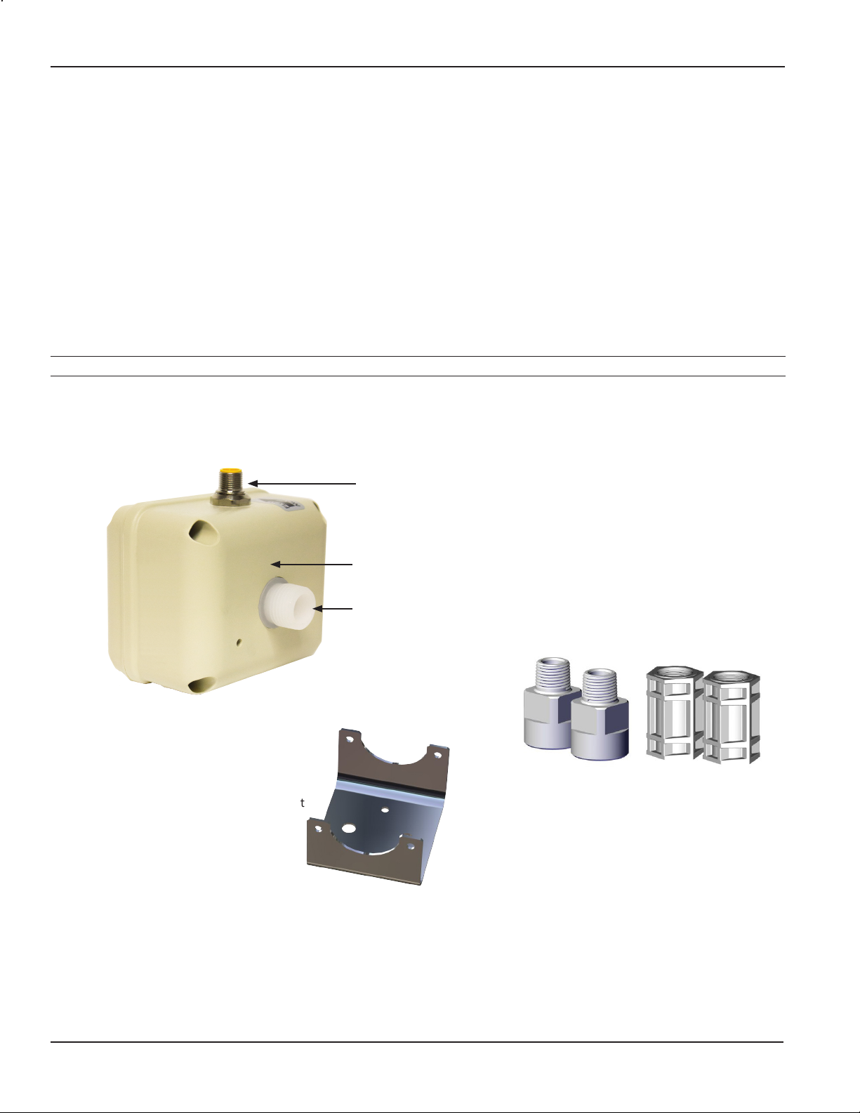
8-pin circular bulkhead connector, 20 foot (6 meter) cable provided
The FMG80A meter is compact enough to t most pump/
injection systems. With zero straight pipe required after
an elbow, it can be easily mounted in tight spaces. The
mounting bracket adds stability.
The FMG80A meter has an optoisolated current sinking
pulse output that can be connected to many Omega rate/
total displays or batch processors, as well as to a 4-20
mA current loop for analog devices. Outputs and power
are provided through a cable with 8-pin female circular
connector.
Mounting bracket
Internals made of chemical and corrosion-resistant PVDF
Sturdy HDPE housing
½” male NPT
ttings standard
Threaded male or female NPT adapters
can be purchased separately
(available in PVDF and PP)
(Female NPT available in 1/2” only)
Page 4 omega.com
Page 5

GENERAL INFORMATION
FMG80A-SERIES INSTRUCTIONS
Specications*
Pipe Size 3/4”, 1/2”, 3/8”, 1/4” **
Fittings 1/2” NPT ttings standard in 3/4” or 3/8” owbody. NPT threaded adapters available for above
Materials Body PVDF
Electrodes PVDF carbon ber lled
Ground PVDF carbon ber lled
Housing HDPE with 25% glass
Adapters (NPT) Polypropylene or PVDF
Temperature Ambient 0˚ to 130˚ F (-18˚ to 54˚ C)
Fluid 32˚ to 200˚ F (0˚ to 93˚ C)
Pressure 150 psi
Flow Range FMG83A, FMG84A 20 GPM max. (0.2 GPM cutoff)
FMG81A, FMG82A 3 GPM max. (0.03 GPM cutoff)
Accuracy FMG83A, FMG84A ±1% plus ±0.005 GPM of reading across rated range
FMG81A, FMG82A ±1% plus ±0.002 GPM of reading across rated range
Output Signal Optoisolated current sinking or current sourcing pulse output: 30 Vdc, 5 mA max
FMG83A, FMG84A 500 pulses/liter (1892 pulses/gallon)
FMG81A, FMG82A 1000 pulses/liter (3785 pulses/gallon)
Power 10–15 Vdc, 150 mA (linear power supply recommended)
Conductivity >20 microSiemens
Empty Pipe Detection Hardware/software, conductivity-based
Environmental
* Specications subject to change • Please consult our website for current data (www.omega.com).
** Requires adaptors
NOTE: Consult factory for applications owing sodium hypochlorite, sodium chlorite, sodium chlorate.
For applications with the listed chemicals, the following conditions apply:
• Max concentration 15% / Max temperature 100˚ F
• Flow is greater than 20% of max for accurate reading
pipe sizes.
Optoisolated 4-20 mA current loop: 7 Vdc plus load voltage drop min; 50 Vdc max
NEMA 4X standard; IP66 splashproof standard
Page 5 omega.com
Page 6
GENERAL INFORMATION
D
C
B
8
7
6
5
4
3
2
1
4.2"
2.1"
-038
.19
-075
.50
D
C
8
7
6
5
4
3
2
1
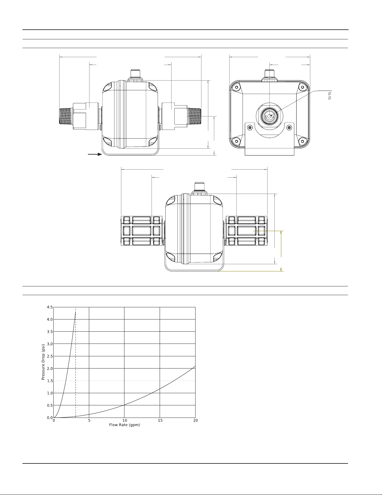
Dimensions
FMG80A-SERIES INSTRUCTIONS
Mounting
Bracket
7.2” (18.3 cm) (with adapters as shown)
7.2" (WITH ADAPTERS AS SHOWN)
4.2” (10.7 cm) (meter without adapters)
4.2" (METER WITHOUT ADAPTERS)
3.5”
3.5"
(8.9 cm)
2.0”
2.0"
(5.0 cm)
7.2” (18.3 cm) (with adapters as shown)
7.2" (WITH ADAPTERS AS SHOWN)
4.2" (METER WITHOUT ADAPTERS)
4.2” (10.7 cm) (meter without adapters)
4.2” (10.7 cm)
4.2"
2.1"
2.1” (5.3 cm)
Meter ID
-038 0.19”
-038
.19
-075
.50
-075 0.50”
3.5”
3.5"
(8.9 cm)
2.0"
2.0”
(5.0 cm)
Pressure Drop Curve
-038
3
FMG83A/FMG84A with 3/4” adapters.
FMG81A/FMG82A with 3/8” adapters.
Actual curve dependant on pipe size/ttings
-075
Page 6 omega.com
Page 7
INSTALLATION
FMG80A-SERIES INSTRUCTIONS
Positioning
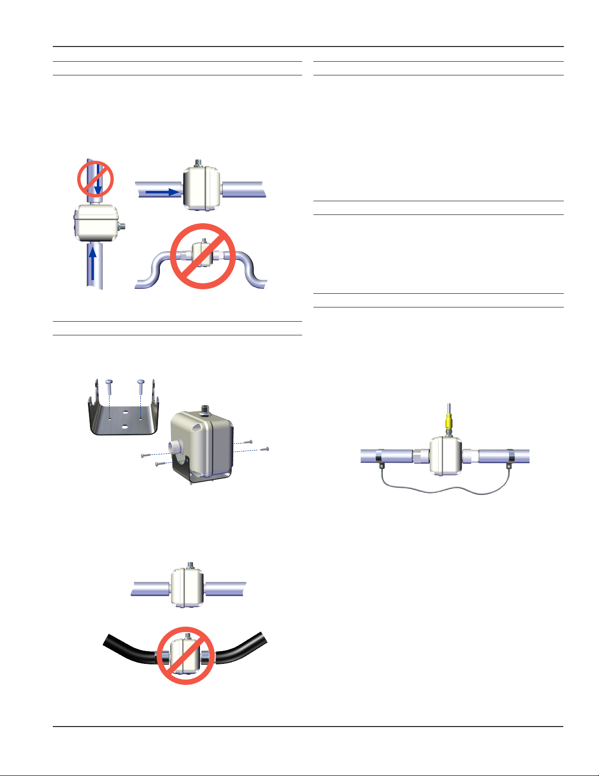
The FMG80A can be mounted vertically or horizontally. It
is important to choose a position that will ensure full pipe.
(Under certain conditions of empty or partially-full pipe
the meter may give a pulse out when there is no ow.)
With a zero straight pipe requirement after an elbow, the
FMG80A meter can be installed in tight spaces.
FLOW
FLOW
FLOW
Mounting
It is highly recommended to use the mounting bracket
provided. The mounting bracket uses two #8 screws on a
1.5” center.
Piping
Metal pipe, metal tube, or plastic tubing can be used with
the meter. The standard NPT ttings can be used with or
without NPT adapters on 3/4” or 3/8” pipe. If used, apply
Teon tape onto the NPT ttings. NPT adapters should be
hand tightened onto the ttings. Thoroughly clean the
pipe threads and nose and apply Teon tape to adapter
threads. Hold adapters with a wrench while tightening the
pipe to prevent damage to the meter.
Power Supply
A 12 Vdc linear, regulated power supply with an output
current of at least 0.25A is recommended. If a switching
power supply must be used, consult Omega for approved
manufacturer’s model numbers.
Grounding
In addition, it is necessary for proper operation to ground
the unit to a good quality earth ground. Assure negative
power supply is grounded to earth and to the entire
electrical/mechanical system. If metal piping is used,
jumper inlet and outlet pipes together and connect to
ground for best results in metering accuracy. The cable
shield drain wire should be left unconnected.
The FMG80A may be supported by its piping connections
IF the piping is rigid. The meter and pipe must be perfectly
aligned with no exion at the ttings to prevent leakage or
damage to the meter.
Page 7 omega.com
Page 8
CONNECTIONS
Green
Green
FMG80A-SERIES INSTRUCTIONS
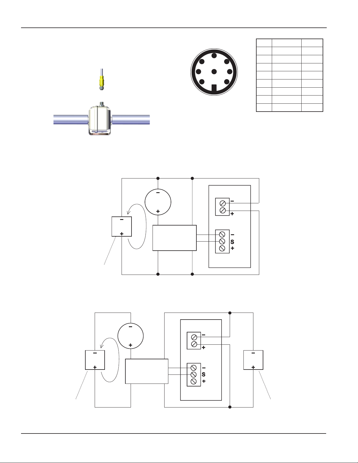
Power and signal connections are provided through the
8-pin male bulkhead connector on the meter housing
(20 ft (6 m) cable provided). See the Pin Assignment and
Connections diagrams.
4-20 mA Device and FMG80 with Single Power Supply
Important: 4-20mA device input resistance must not exceed 250 Ω
_
4-20 mA
device
+
7
4
Blue
FMG80A
_
12–15
Vdc
+
4-20 mA
loop
5
4
6
3 7
8
2
Cable Plug Contact
Arrangement
Power
Brown
2
White
1
3
8
1
_
+
DISPLAY
_
S
+
Pin # Function Color
1 Pulse (-) White
2 Ground Brown
3 Pulse (+) Green
4 4-20 (+) Yellow
5 Not used Grey
6 Not used Pink
7 4-20 (-) Blue
8 Power (+) Red
May be external
or internal to the
display device
May be external
or internal to the
display device
4-20 mA
_
24
Vdc
+
loop
Sensor Input
Yellow
Red
Dual Power Supply with Loop Isolation
_
4-20 mA
device
+
7
4
Blue
FMG80A
Yellow
2
8
1
3
Brown
White
Red
Power
_
+
DISPLAY
_
S
+
Sensor Input
_
12–15
Vdc
+
May be external
or internal to the
display device
Page 8 omega.com
Page 9
OPERATION AND TROUBLESHOOTING
OPERATION
FMG80A-SERIES INSTRUCTIONS
The meter will output one pulse when powered up. The
newly-installed meter takes from a few seconds to a minute
for the signal to stabilize at startup, especially if it has been
dry. In normal operation, keep the meter lled with uid
and powered on to prevent this delay. When the meter
is mounted properly, an empty pipe detection feature will
normally detect absence of liquid in the pipe and register
zero ow.
The 4-20 mA signal outputs 4 mA at zero ow and 20 mA at
20 gallons/minute ow or 3 gallons per minute, depending
on model.
The pulse signal is a 50% duty cycle pulse set at:
FMG83A/FMG84A:
500 pulses/liter (1892 pulses/gallon)
FMG81A/FMG82A:
1,000 pulses/liter (3785 pulses/gallon)
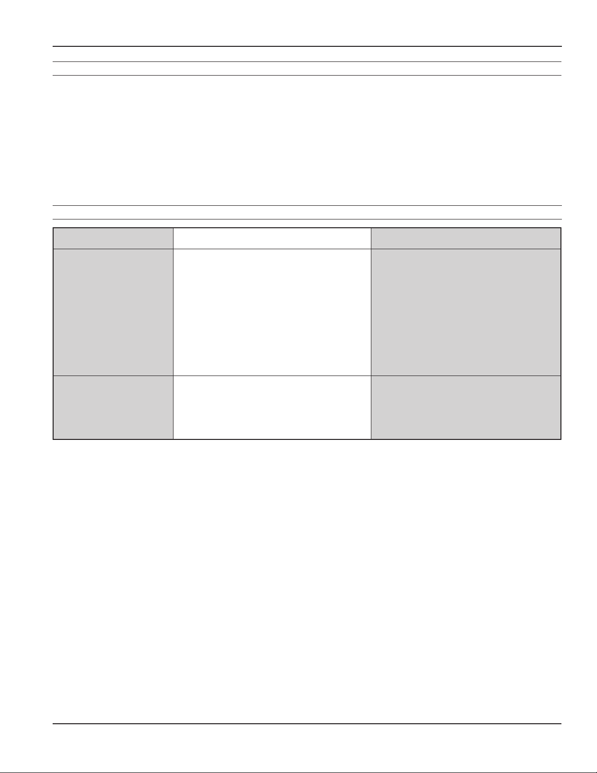
TROUBLESHOOTING
Problem Probable Causes Things to try…
No output Reversed ow direction Reverse ow connections
Empty pipe Check piping conditions
Flow rate below minimum Select a different ow meter
Loose or incorrect wiring Check electrical connections
Fluid conductivity too low Select a different ow meter
Electrical noise Relocate meter or reduce noise
Flow rate incorrect Fluid conductivity too low Select a different ow meter
Empty pipe Check piping conditions
Electrical noise Relocate meter or reduce noise
Page 9 omega.com
Page 10

NOTES
FMG80A-SERIES INSTRUCTIONS
Page 10 omega.com
Page 11

WARRANTY/DISCLAIMER
OMEGA ENGINEERING, INC. warrants this unit to be free of defects in materials and workmanship for a
period of 13 months from date of purchase. OMEGA’s WARRANTY adds an additional one (1) month
grace period to the normal one (1) year product warranty to cover handling and shipping time. This
ensures that OMEGA’s customers receive maximum coverage on each product.
If the unit malfunctions, it must be returned to the factory for evaluation. OMEGA’s Customer Service
Department will issue an Authorized Return (AR) number immediately upon phone or written request.
Upon examination by OMEGA, if the unit is found to be defective, it will be repaired or replaced at no
charge. OMEGA’s WARRANTY does not apply to defects resulting from any action of the purchaser,
including but not limited to mishandling, improper interfacing, operation outside of design limits,
improper repair, or unauthorized modification. This WARRANTY is VOID if the unit shows evidence of
having been tampered with or shows evidence of having been damaged as a result of excessive corrosion;
or current, heat, moisture or vibration; improper specification; misapplication; misuse or other operating
conditions outside of OMEGA’s control. Components in which wear is not warranted, include but are not
limited to contact points, fuses, and triacs.
OMEGA is pleased to offer suggestions on the use of its various products. However,
OMEGA neither assumes responsibility for any omissions or errors nor assumes liability for
any damages that result from the use of its products in accordance with information provided
by OMEGA, either verbal or written. OMEGA warrants only that the parts manufactured by the
company will be as specified and free of defects. OMEGA MAKES NO OTHER WARRANTIES OR
REPRESENTATIONS OF ANY KIND WHATSOEVER, EXPRESSED OR IMPLIED, EXCEPT THAT OF
TITLE, AND ALL IMPLIED WARRANTIES INCLUDING ANY WARRANTY OF MERCHANTABILITY
AND FITNESS FOR A PARTICULAR PURPOSE ARE HEREBY DISCLAIMED. LIMITATION OF
LIABILITY: The remedies of purchaser set forth herein are exclusive, and the total liability of
OMEGA with respect to this order, whether based on contract, warranty, negligence,
indemnification, strict liability or otherwise, shall not exceed the purchase price of the
component upon which liability is based. In no event shall OMEGA be liable for
consequential, incidental or special damages.
CONDITIONS: Equipment sold by OMEGA is not intended to be used, nor shall it be used: (1) as a “Basic
Component” under 10 CFR 21 (NRC), used in or with any nuclear installation or activity; or (2) in medical
applications or used on humans. Should any Product(s) be used in or with any nuclear installation or
activity, medical application, used on humans, or misused in any way, OMEGA assumes no responsibility
as set forth in our basic WARRANTY/DISCLAIMER language, and, additionally, purchaser will indemnify
OMEGA and hold OMEGA harmless from any liability or damage whatsoever arising out of the use of the
Product(s) in such a manner.
RETURN REQUESTS/INQUIRIES
Direct all warranty and repair requests/inquiries to the OMEGA Customer Service Department.
BEFORE RETURNING ANY PRODUCT(S) TO OMEGA, PURCHASER MUST OBTAIN AN AUTHORIZED
RETURN (AR) NUMBER FROM OMEGA’S CUSTOMER SERVICE DEPARTMENT (IN ORDER TO AVOID
PROCESSING DELAYS). The assigned AR number should then be marked on the outside of the return
package and on any correspondence.
The purchaser is responsible for shipping charges, freight, insurance and proper packaging to prevent
breakage in transit.
FOR WARRANTY RETURNS, please have the
following information available BEFORE contacting
OMEGA:
1. Purchase Order number under which the product
was PURCHASED,
2. Model and serial number of the product under
warranty, and
3. Repair instructions and/or specific problems
relative to the product.
OMEGA’s policy is to make running changes, not model changes, whenever an improvement is possible. This affords
our customers the latest in technology and engineering.
OMEGA is a registered trademark of OMEGA ENGINEERING, INC.
© Copyright 2016 OMEGA ENGINEERING, INC. All rights reserved. This document may not be copied, photocopied,
reproduced, translated, or reduced to any electronic medium or machine-readable form, in whole or in part, without the
prior written consent of OMEGA ENGINEERING, INC.
FOR NON-WARRANTY REPAIRS,
OMEGA for current repair charges. Have
the following information available BEFORE
contacting OMEGA:
1. Purchase Order number to cover the COST
of the repair,
2. Model and serial number of the product, and
3. Repair instructions and/or specific problems
relative to the product.
consult
Page 12

Where Do I Find Everything I Need for
Process Measurement and Control?
OMEGA…Of Course!
Shop online at omega.com
TEMPERATURE
MU
Thermocouple, RTD & Thermistor Probes, Connectors, Panels & Assemblies
MU
Wire: Thermocouple, RTD & Thermistor
MU
Calibrators & Ice Point References
MU
Recorders, Controllers & Process Monitors
MU
Infrared Pyrometers
PRESSURE, STRAIN AND FORCE
MU
Transducers & Strain Gages
MU
Load Cells & Pressure Gages
MU
Displacement Transducers
MU
Instrumentation & Accessories
FLOW/LEVEL
MU
Rotameters, Gas Mass Flowmeters & Flow Computers
MU
Air Velocity Indicators
MU
Turbine/Paddlewheel Systems
MU
Totalizers & Batch Controllers
SM
pH/CONDUCTIVITY
MU
pH Electrodes, Testers & Accessories
MU
Benchtop/Laboratory Meters
MU
Controllers, Calibrators, Simulators & Pumps
MU
Industrial pH & Conductivity Equipment
DATA ACQUISITION
MU Communications-Based Acquisition Systems
MU Data Logging Systems
MU Wireless Sensors, Transmitters, & Receivers
MU Signal Conditioners
MU Data Acquisition Software
HEATERS
MU
Heating Cable
MU
Cartridge & Strip Heaters
MU
Immersion & Band Heaters
MU
Flexible Heaters
MU
Laboratory Heaters
ENVIRONMENTAL
MONITORING AND CONTROL
MU
Metering & Control Instrumentation
MU
Refractometers
MU
Pumps & Tubing
MU
Air, Soil & Water Monitors
MU
Industrial Water & Wastewater Treatment
MU
pH, Conductivity & Dissolved Oxygen Instruments
LT-65200362r1.1 20161116
11/16/16
M-5468/1116
 Loading...