

Page 1
User's Guide
Shop online at
omega.com
email: [email protected]
For latest product manuals:
omegamanual.Info
FMG-800 SERIES
Plastic Bodied Magmeter
Page 2

OMEGAnet®Online Service Internet e-mail
It is the policy of OMEGA Engineering, Inc. to comply with all worldwide safety and EMC/EMI
regulations that apply. OMEGA is constantly pursuing certification of its products to the European New
Approach Directives. OMEGA will add the CE mark to every appropriate device upon certification.
omega.com i n f o @ o m e g a . c o m
Servicing North America:
U.S.A.: One Omega Drive, P.O. Box 4047
ISO 9001 Certified
Stamford, CT 06907-0047
TEL: (203) 359-1660 FAX: (203) 359-7700
e-mail: [email protected]
Canada: 976 Bergar
Laval (Quebec) H7L 5A1, Canada
TEL: (514) 856-6928 FAX: (514) 856-6886
e-mail: [email protected]
For immediate technical or application assistance:
U.S.A. and Canada: Sales Service: 1-800-826-6342 / 1-800-TC-OMEGA
Customer Service: 1-800-622-2378 / 1-800-622-BEST
Engineering Service: 1-800-872-9436 / 1-800-USA-WHEN
TELEX: 996404 EASYLINK: 62968934 CABLE: OMEGA
Mexico: En Espan˜ol: (001) 203-359-7803 e-mail: [email protected]
FAX: (001) 203-359-7807 [email protected]
®
®
®
Servicing Europe:
Benelux: Postbus 8034, 1180 LA Amstelveen, The Netherlands
TEL: +31 (0)20 3472121 FAX: +31 (0)20 6434643
Toll Free in Benelux: 0800 0993344
e-mail: [email protected]
Czech Republic: Frystatska 184, 733 01 Karviná, Czech Republic
France: 11, rue Jacques Cartier, 78280 Guyancourt, France
TEL: +33 (0)1 61 37 2900 FAX: +33 (0)1 30 57 5427
Toll Free in France: 0800 466 342
e-mail: [email protected]
Germany/Austria: Daimlerstrasse 26, D-75392 Deckenpfronn, Germany
TEL: +49 (0)7056 9398-0 FAX: +49 (0)7056 9398-29
Toll Free in Germany: 0800 639 7678
e-mail: [email protected]
United Kingdom: One Omega Drive, River Bend Technology Centre
ISO 9002 Certified
Northbank, Irlam, Manchester
M44 5BD United Kingdom
TEL: +44 (0)161 777 6611 FAX: +44 (0)161 777 6622
Toll Free in United Kingdom: 0800-488-488
e-mail: [email protected]
The information contained in this document is believed to be correct, but OMEGA accepts no liability for any
errors it contains, and reserves the right to alter specifications without notice.
WARNING: These products are not designed for use in, and should not be used for, human applications.
Page 3

TABLE OF CONTENTS
General Information
General Information, Features, Models ......................................................................................Page 1
Specications
Specications, Dimensions.........................................................................................................Page 2
Installation and Grounding
Flow Range, Positioning the Meter,
Piping Conditions, End Connections, Position ..........................................................................Page 3
Straight and Full Pipe Recommendations ......................................................................... Page 4
Electrical Connections, Cable Connections, Operation, Grounding.................................Page 5
Maintenance, Repair, Troubleshooting
Battery Replacement,Problem, Probable Cause, Things to Try ......................................................Page 6
Fittings, Piping Conditions, End Connections
TABLES, DIAGRAMS & CHARTS
Features, Models .................................................................................................................... Page 1
Specifications, Dimensions ..................................................................................................... Page 2
Flow Range ............................................................................................................................ Page 3
Straight and Full Pipe Recommendations ................................................................................ Page 4
Cable Connections ................................................................................................................. Page 5
Troubleshooting ....................................................................................................................... Page 6
Page 4
GENERAL INFORMATION and FEATURES
GENERAL INFORMATION
The FMG800 Series is a full-bore, plastic-bodied electromagnetic
ow meter designed for ow and usage monitoring applications
in 1, 2 and 3 inch pipe. The polypropylene ow tube offers corrosion resistance to a wide range of chemicals. Its light weight
and easy to install or remove from the pipe for inspection.
With no moving parts, the magmeter permits unobstructed ow,
minimizing ow disturbances and hence, straight pipe requirements. The FMG800 Series can be used in piping congurations
where there is little space between the meter and an elbow or
valve. The FMG800 Series, like other magmeters, are resistant
to wear from sand and debris found in ground or surface water.
Since there are no bearings or propeller to wear out, downtime
and maintenance and repair costs are kept to a minimum.
Because there are no mechanical parts in the ow stream, the
meter tolerates high ows without damage.
The hinged, opaque polyethylene cover protects from dust and
UV rays, while permitting easy access to the LCD ow rate and
total display. The electronics housing is made of rugged powder-coated die-cast aluminum. It can be tted with cross-drilled
screws and seal wire for tamper-evidence. Flow rate and total
can be displayed in a variety of units, customer-selected and
factory-set.
The FMG800 Series is used for tracking ow rate and total
ow in usage monitoring applications, for instance, in compliance with regulatory requirements. These would include wells,
industrial wastewater, gray water, irrigation metering, turf and
landscape applications, and other water reclamation operations.
In the event of DC power loss, or when changing the battery, the
FMG800 is designed to retain the internal settings and ow total.
The FMG81x is externally powered via a 5-pin connector and
the power cable also provides pulse output for use with a variety
of displays and controls for remote reading, data logging, pulseto-analog conversion, and telemetry applications.
The FMG80x is a battery-operated unit for use when pulse
output is not required. The standard batteries are user
replaceable with an approximate 1 year life depending on
usage.
Model Description
FMG801 1” Battery Powered Magmeter
FMG802 2” Battery Powered Magmeter
FMG803 3” Battery Powered Magmeter
FMG811 1” DC Powered Magmeter 1 Pulse/Gal Output
FMG812 2” DC Powered Magmeter 1 Pulse/Gal Output
FMG813 3” DC Powered Magmeter 1 Pulse/Gal Output
FMG811-HF 1” DC Powered Magmeter High Frequency Output
FMG812-HF 2” DC Powered Magmeter High Frequency Output
FMG813-HF 3” DC Powered Magmeter High Frequency Output
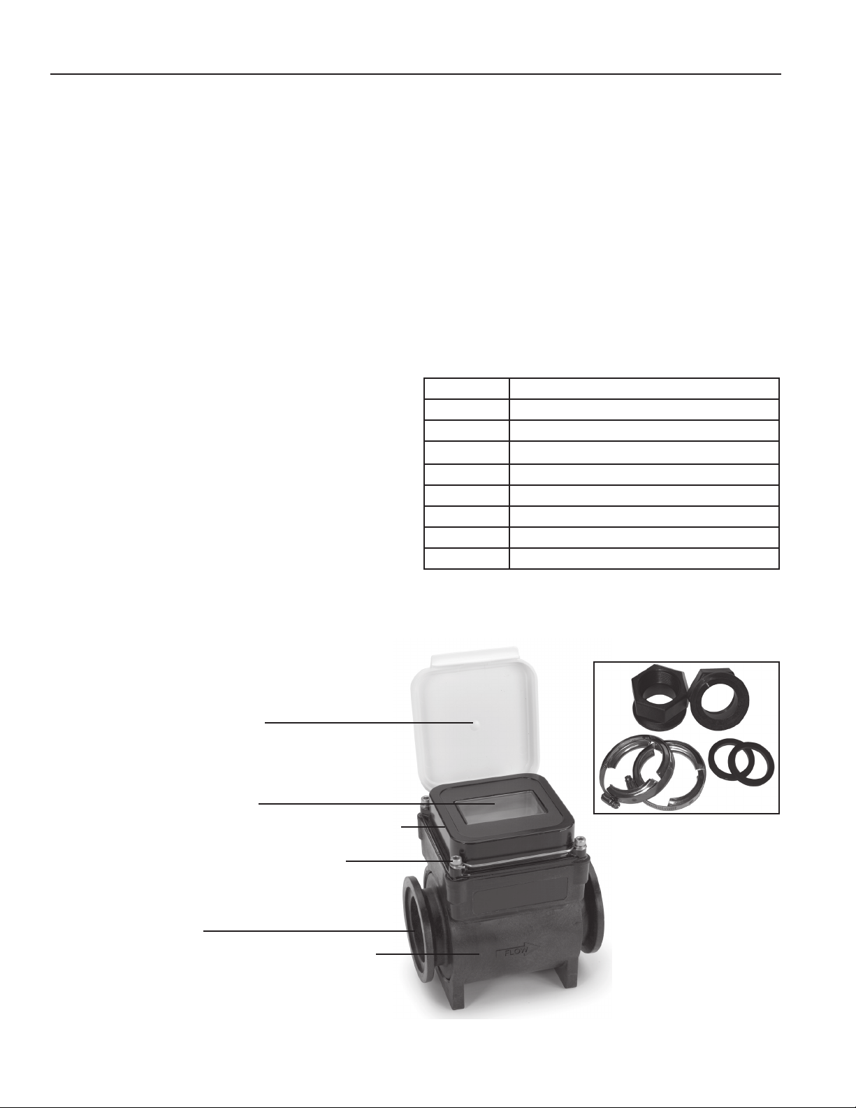
FEATURES
Polyethylene protective cover
LCD rate and total indicator
Powder-coated die cast-aluminum electronics housing
Cross-drilled screws (2) for tamper-evidence
316SS electrodes
Corrosion-resistant glass-lled polypropylene body
Lightweight for easy handling
Fitting Kit for 2” and 3” models
2 inch
1
Page 5
4.625”
10.75”
4.40”
3.00”
7.30”
7.30”
2.625”
SPECIFICATIONS*
Pipe Size
Fittings
Pressure
Operating Temperature Range
Accuracy
Flow Range
Materials
Minimum
Maximum
Body
Electrodes
Electronics Housing
Display
Display Cover
Digits
Units
Security
Power
Pulse Output Signal
Pulse Rate
FMG81x
FMG80x
(FMG81x Only)
(FMG81x Only)
Low Frequency
Pulse
High Frequency
/Unit
Empty Pipe Detection
Conductivity
Environmental
Electrical Connection (FMG81x Only)
1, 2 or 3 inch full port
1 inch NPTF, 2 or 3 inch ange clamps with 2 or 3 inch NPTF tting kit
150 psi or 10.3 bar working pressure @ 70˚ F
10˚ to 130˚ F (-12˚ to 54˚ C) operating, -40˚ to 176˚ F (-40˚ to 80˚ C) non-operating
+/-1% of reading (between 10% and 100% of max ow)
+/-3% of reading (between cutoff and 10% of max ow)
1 inch: 2.3 GPM (.145 LPS) 2 inch: 6 GPM (.38 LPS) 3 inch: 14 GPM (.88 LPS)
1 inch: 110 GPM (6.94 LPS) 2 inch: 300 GPM (18.9 LPS) 3 inch: 670 GPM (42.3 LPS)
Glass-lled polypropylene
316 stainless steel
Diecast aluminum, powder-coated
Polyethylene
Rate Total
6 8
Gallons/Minute, Cubic Feet/Second, Acre-Feet, Acre-Inch, Gallons, Gallons x 1000,
Cubic Feet/Minute, Liters/Second Cubic Feet, Liters, Megaliters, Cubic Meters
Liters/Minute, Cubic Meters/Minute
Cross-drilled screws and tamper-evident seal (optional)
10-30 Vdc @ 60 mA max (15 mA average)
NOTE: Using an unregulated power supply >18 Vdc may damage the meter due to AC line input voltage uctuation
6 each AA alkaline cells, replaceable. Estimated life is 1 year depending on usage
Current sinking pulse, opto isolated, 32 Vdc max at 10 mA max
1 unit/pulse out, pulse width of 10ms depending on unit selection
1” 2” 3” Pulse width 1.1 ms, min - max frequency, 3 - 150 hz
80 30 13
Hardware/software, conductivity-based
>20 microSiemens/cm
NEMA 4X standard
5 pin male circular connector, mates to industry standard cable
*Specications subject to change
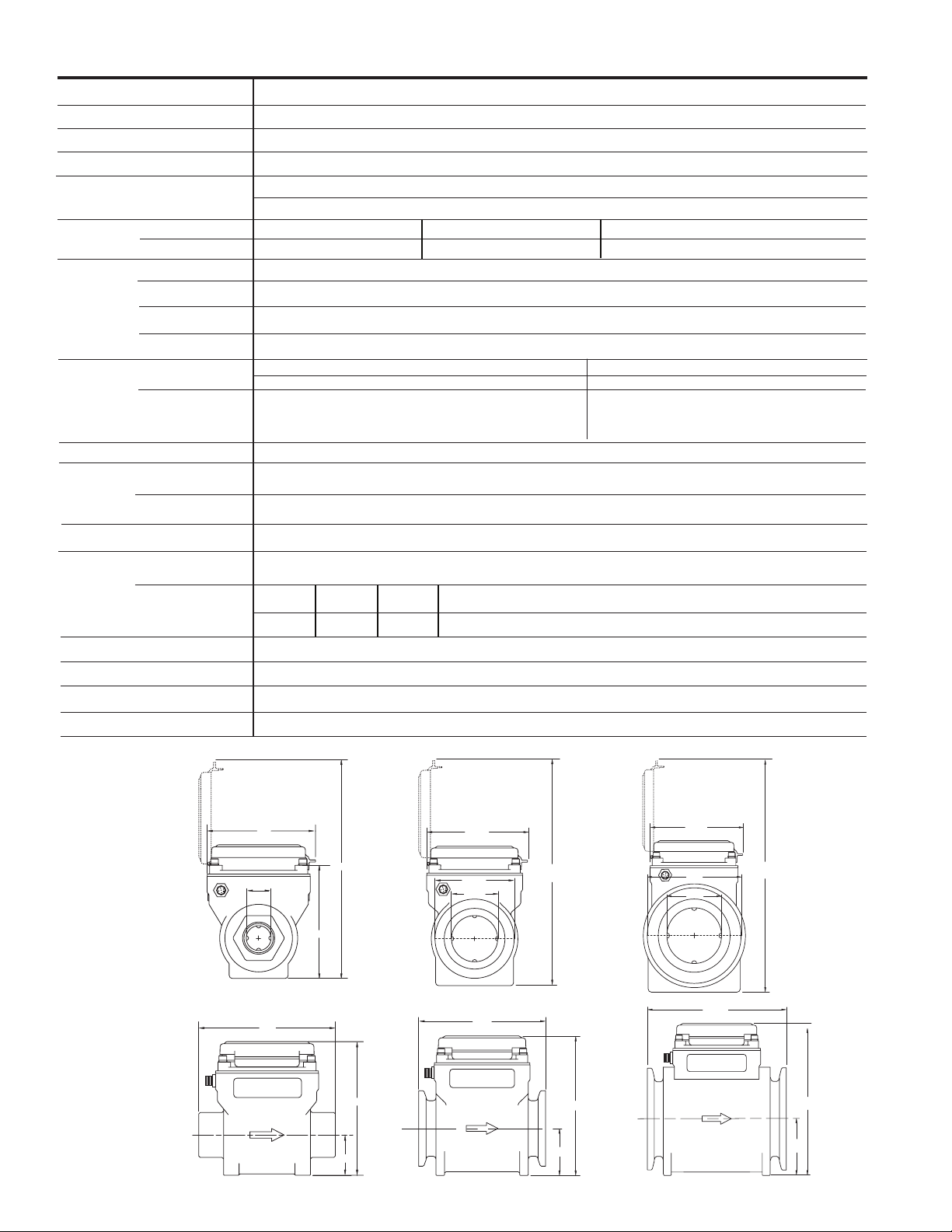
DIMENSIONS
Power/Output Cable
- FMG81x Only
1 Inch
4.3”
1.00”
5.50”
4.55”
8.8”
1.63”
5.38”
2 Inch
4.625”
3.25”
2.00”
5.50”
3 Inch
9.50”
6.03”
2.03”
2
Page 6
FLOW RANGE, INSTALLATION
FLOW RANGE
1” 2” 3”
Gal/Min Liter/Sec Gal/Min Liter/Sec Gal/Min Liter/Sec
Minimum
2.3 .145 6 .38 14 .88
Maximum
110 6.94 300 18.9 670 42.3
INSTALLATION
Piping Conditions. Installing the meter with a length of
straight pipe at least two times the diameter upstream and
one diameters downstream is highly recommended. Some
piping conditions require more than this. See chart for rec-
ommendations.
Step 1.
Position gasket
at either end
Step 2.
Place adapter
against gasket,
open screw clamps
to clear anges
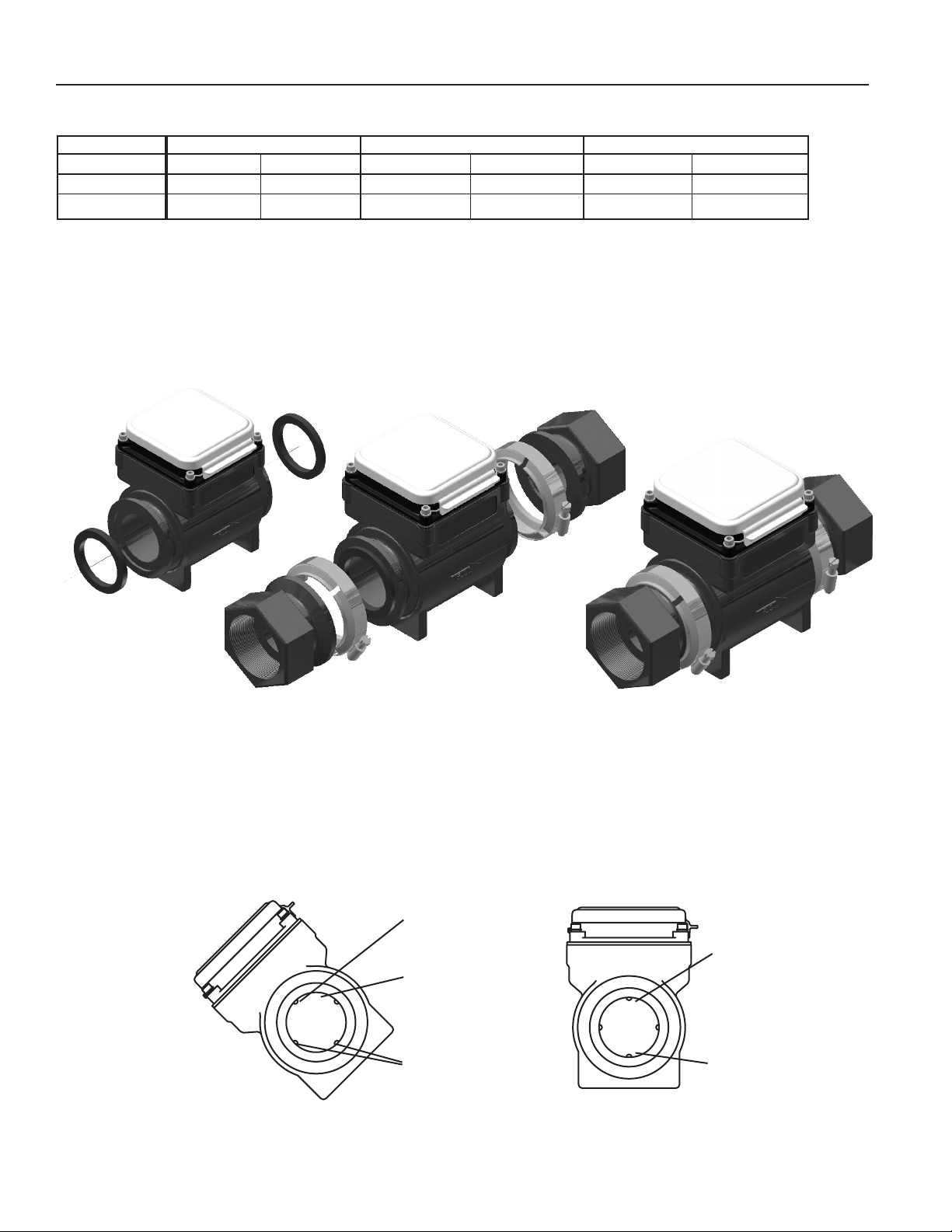
End Connections. The meter comes with union-type ange
connections for ease in servicing the meter. To connect these
to piping ends, a variety of kits are available.
Follow the diagram below to make the connections.
Step 3.
Place screw-clamps
over both adapter
and meter anges
and tighten screws
NOTE: Above installation instructions are for FMG802/812 (2”) and FMG803/813 (3”) only. The FMG801/811 (1”) is provided with intergrated NPT female threaded ends.
Position. This is an all position meter which can be installed either vertically or horizontally, register up, down or angled. How-
ever, entrained air or solids may make some positions preferable to others. See the position diagram for guidance.
Recommended:
May prevent sediment
or bubble problems
Electrode
moved from
top by rotating
meter
Intermittent air
bubbles
miss electrode
Electrodes free
from sediment
build-up
Air bubbles and sediment on the
electrodes can affect accuracy
FMG800FMG800
Intermittent air
bubbles
pass over
electrode
Possible
sediment
build-up
Less Ideal:
3
Page 7
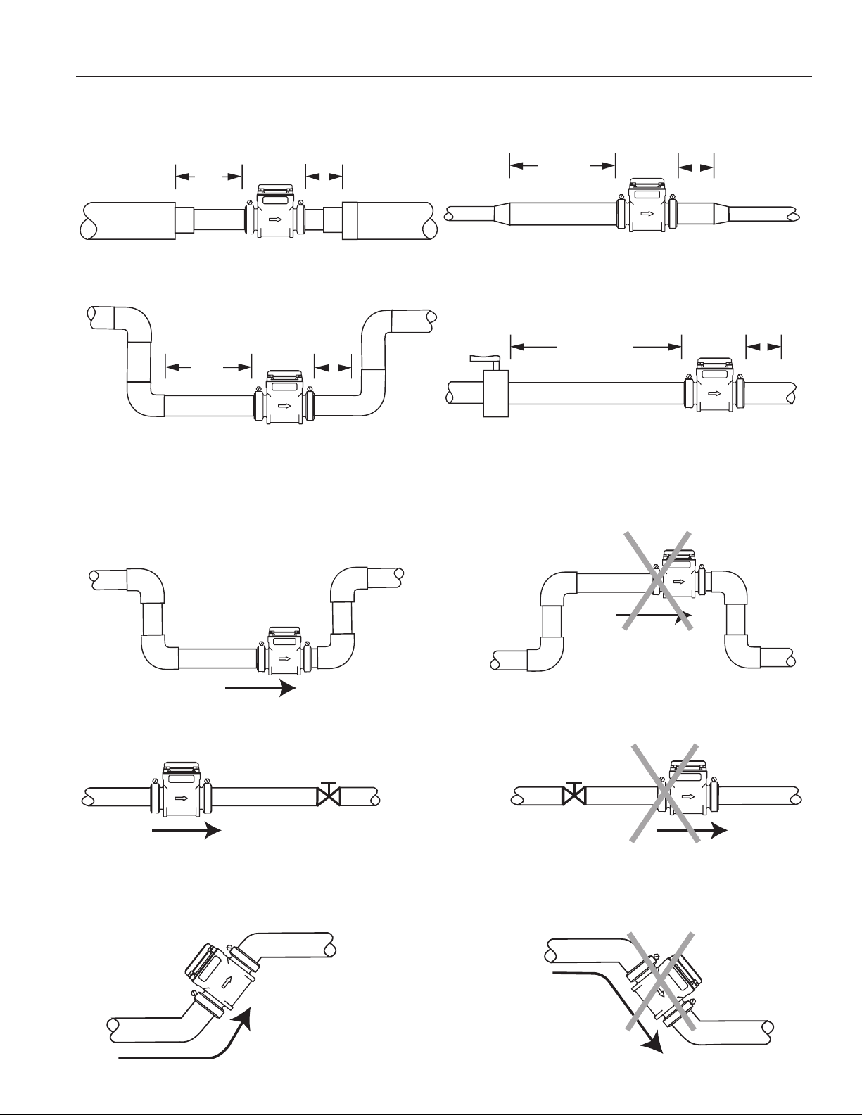
STRAIGHT and FULL PIPE RECOMMENDATIONS
(X = diameter)
Reduced Pipe
Elbows
2X
2X
FMG800
FMG800
1X
1X
Expanded Pipe
Swirling Flow:
5X
Partially Open
Buttery Valve
1X
FMG800
1X
5X
FMG800
Recommended:
Keep pipe full at meter
for accuracy
FMG800
FMG800
Recommended:
Keeps pipe full at meter for accuracy
FMG800
Not Ideal:
Allows air pockets to form at meter
FMG800
Not Ideal:
Post-valve cavitation can create air pocket
FMG800
Recommended:
Allows air to bleed off
FMG800
Not Ideal:
Air can be trapped
4
Page 8
ELECTRICAL CONNECTIONS, CABLE CONNECTIONS and OPERATION
ELECTRICAL CONNECTIONS
FMG80x. The FMG80x is battery-powered totally self-con-
tained and does not require any electrical connections (there
is no output on the FMG80x model).
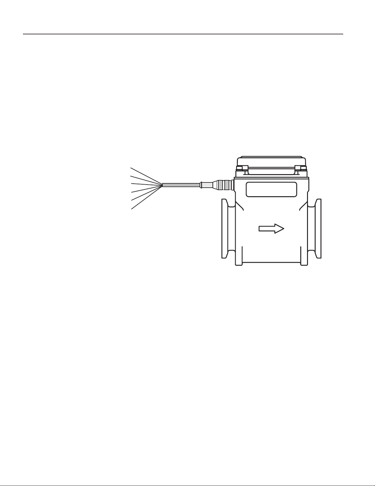
CABLE CONNECTIONS
Gray: Pin 5 = Ground
White: Pin 4 = (–) Pulse
Blue: Pin 3 = (+) Pulse
Black: Pin 2 = (–) Power
Brown: Pin 1 = (+) Power
Shield Drain Wire
FMG81x. A connector is provided on the outside of the
FMG81x. To connect to the meter, plug the cable in and hand
tighten the retaining threads. Follow the diagram to make
connections. If you are using the pulse output, connect power
rst and determine that the meter is working properly by ob-
serving the display. Then connect the pulse output.
OPERATION
Grounding (FMG81x). For best performance, especially in
chemically noisy environments, the gray ground wire and the
bare drain wire should be connected together and to a good
earth ground as close to the meter as possible. Metal pipe
and ttings in contact with the uid should also be bonded to
the same earth ground with corrosion-resistant connections.
Display. The display reads ow rate and accumulated total,
in the units for which it was ordered. The top line is total, the
bottom line is rate, and indicators give the units (ac-ft, GPM
for instance.) Empty or partially-full pipe is automatically detected and is indicated by a reading of “ – EP – “.
Battery. The AA Alkaline batteries are user replaceable with
an approximate 1 year life depending on usage. On the battery-powered FMG80x there is a low-battery indicator (“low
bat”) when the battery voltage drops below a certain point.
Batteries should be changed within four weeks of the ap-
pearance of this indicator.
5
Page 9

MAINTENANCE, REPAIR and TROUBLE SHOOTING
MAINTENANCE AND REPAIR
There are no user-serviceable parts in the FMG800 Series
meters except the batteries in the FMG81x.
Battery Replacement. When the “low bat” indicator appears,
the batteries should be changed. Six AA alkaline cells are required. To change the batteries, rst remove the four screws
which hold the top cover in place. Be careful not to lose the
wash ers. Move the top cover to one side and remove the
foam retainer which covers the battery tray or pack.
> Remove the old AA alkaline bat teries from the battery tray,
and replace them with fresh ones, taking care to fol low the
polarity indicators in the battery tray.
Replace the foam retainer, then put the top cover back in
place. Warning! Use Extreme Caution not to pinch wiring or
other assembly parts under the housing seal - this may cause
an ingress of water, voiding the product warranty. Replace the
four screws and washers, then tighten them securely using
cross-pattern to evenly compress the gasket. Environmental
and Safety note - take care to dispose of all batteries in ac-
cordance with Federal, State, and Local regulations.
TROUBLE SHOOTING
Problem
Blank display:
FMG81x
Blank display:
FMG80x
Reading “-EP-”
Flow but no ow rate reading
Probable Cause Try...
No power to unit
Batteries dead or misinstalled
Empty or partly lled pipe
Excessive air pockets or foaming
Heavily coated electrodes
Check power supply
Check wiring
Check polarity, replace batteries
Rearrange piping to ensure full pipe
Remove meter and wipe electrodes
6
Page 10

WARRANTY/DISCLAIMER
FOR NON-WARRANTY REPAIRS,
OMEGA ENGINEERING, INC. warrants this unit to be free of defects in materials and workmanship for a
period of 13 months f rom date of purchase. OMEGA’s WARRANTY adds an additional one (1) month
grace period to the normal one (1) year product warranty to cover handling and shipping time. This
ensures that OMEGA’s customers receive maximum coverage on each product.
If the unit malfunctions, it must be re t u r ned to the factory for evaluation. O M E G A’s Customer Serv i c e
D e p a rtm ent will issue an Authorized Return (AR) number immediately upon phone or written re q u e s t .
Upon examination by OMEGA, if the unit is found to be defective, it will be re p a i red or replaced at no
c h a rge. O M E G A ’s WARRANTY does not apply to defects resulting from any action of the purc h a s e r ,
including but not limited to mishandling, improper interfacing, operation outside of desi
i m p roper re p a i r , or unauthorized modification. This WARRANTY is VOID if the unit shows evidence of
having been tampered with or shows evidence of having been damaged as a result of excessive corro s i o n ;
or current, heat, moisture or vibration; improper specification; misapplication; misuse or other operating
conditions outside of OMEGA’s c o n t r ol. Components in which wear is not warranted, include but are not
limited to contact points, fuses, and triacs.
OMEGA is pleased to offer suggestions on the use of its various product s. However,
OMEGA neither assumes responsibility for any omissions or e
damages that result from the use of its products in accordance with information provided by
OMEGA, either verbal or written. OMEGA warrants only that the parts manufactured by the
company will be as specified and free of defects. OMEGA MAKES NO OTHER WARRANTIES OR
R E P R E S E N T ATIONS OF ANY KIND WHATSOEVER, EXPRESSED OR IMPLIED, EXCEPT THAT OF
TITLE, AND ALL IMPLIED WARRANTIES INCLUDING ANY W
AND FITNESS FOR A PA R TICULAR PURPOSE ARE HEREBY DISCLAIMED. LIMITATION OF
L I A B I L I T Y: The remedies of purchaser set forth herein are exclusive, and the total liability of
OMEGA with respect to this ord e r , whether based on contract, warr a n t y, negligence,
indemnification, strict liability or otherwise, shall not exceed the purchase price of the
compone nt upo n which li abili ty is based. I n no event shall OMEGA be liabl e for
co
nsequential, incidental or special damages.
CONDITIONS: Equipment sold by OMEGA is not intended to be used, nor shall it be used: (1) as a “Basic
Component” under 10 CFR 21 (NRC), used in or with any nuclear installation or activity; or (2) in medical
applications or used on humans. Should any Product(s) be used in or with any nuclear installation or
a c t i v i t y , medical application, used on humans, or misused in any way, OMEGA assumes no re s p o n s i b i l i t y
as set forth in our basic WA R R A N T Y/ D ISCLAIMER language, and, additionally, purchaser will indemnify
OMEGA and hold OMEGA h a rmless from any liability or damage whatsoever arising out of the use of the
P roduct(s) in such a manner.
rrors nor assumes liability for any
ARRANTY OF MERCHANTA B I L I T Y
gn limits,
RETURN REQUESTS/INQUIRIES
Direct all warranty and repair requests/inquiries to the OMEGA Customer Service Department. BEFORE
RETURNING ANY PRODUCT(S) TO OMEGA, PURCHASER MUST OBTAIN AN AUTHORIZED RETURN
(AR
) NUMB ER FROM OMEG A’S CUS T OMER SERVIC E DEPA R T MENT ( IN ORDER T O AV O I D
PROCESSING DELAYS). The assigned AR number should then be marked on the outside of the return
package and on any correspondence.
The purchaser is responsible for shipping charges, freight, insurance and proper packaging to prevent
breakage in transit.
WARRANTY RETURNS, please have the
FOR
following information available BEFORE
contacting OMEGA:
1 . P u r chase Order number under which the pro d u c t
was PURCHASED,
2. Model and serial number of the product under
warranty, and
3. Repair instructions and/or specific problems
relative to the product.
OMEGA’s policy is to make running changes, not model changes, whenever an improvement is possible. This affords
our customers the latest in technology and engineering.
OMEGA is a registered trademark of OMEGA ENGINEERING, INC.
© Copyright 2005 OMEGA ENGINEERING, INC. All rights reserved. This document may not be copied, photocopied,
reproduced, translated, or reduced to any electronic medium or machine-readable form, in whole or in part, without the
prior written consent of OMEGA ENGINEERING, INC.
for current repair charges. Have the following
information available BEFORE contacting OMEGA:
1. Purchase Order number to cover the COST
of the repair,
2. Model and serial number of the product, and
3. Repair instructions and/or specific problems
relative to the product.
consult OMEGA
Page 11

Notes
Page 12

W h e r e Do I Find Eve rything I Need for
P r ocess Measurement and Control?
OME GA…Of Cours e !
Shop online at omega.com
T E M P E R A T U R E
Thermocouple, RTD & Thermistor Probes, Connectors, Panels & Assemblies
Wire: Thermocouple, RTD & Thermistor
Calibrators & Ice Point References
Recorders, Controllers & Process Monitors
Infrared Pyrometers
PRESSURE, STRAIN AND FO R C E
Transducers & Strain Gages
Load Cells & Pressure Gages
Displacement Transducers
Instrumentation & Accessories
F L OW / L E V E L
Rotameters, Gas Mass Flowmeters & Flow Computers
Air Velocity Indicators
Turbine/Paddlewheel Systems
Totalizers & Batch Controllers
p H / C O N D U C T I V I T Y
pH Electrodes, Testers & Accessories
Benchtop/Laboratory Meters
Controllers, Calibrators, Simulators & Pumps
Industrial pH & Conductivity Equi
pment
DATA AC Q U I S I T I O N
Data Acquisition & Engineering Software
Communications-Based Acquisition Systems
Plug-in Cards for Apple, IBM & Compatibles
Datalogging Systems
Recorders, Printers & Plotters
H E A T E R S
Heating Cable
Cartridge & Strip Heaters
Immersion & Band Heaters
Flexible Heaters
Laboratory Heaters
E N V I R O N M E N T A L
M O N I T ORING AND CONTRO L
Metering & Control Instrumentation
R e f r a c t o m e t e r s
Pumps & Tubing
Air, Soil & Water Monitors
Industrial Water & Wastewater Treatment
pH, Conductivity & Dissolved Oxygen Instruments
M-5122/0312
 Loading...