

Page 1
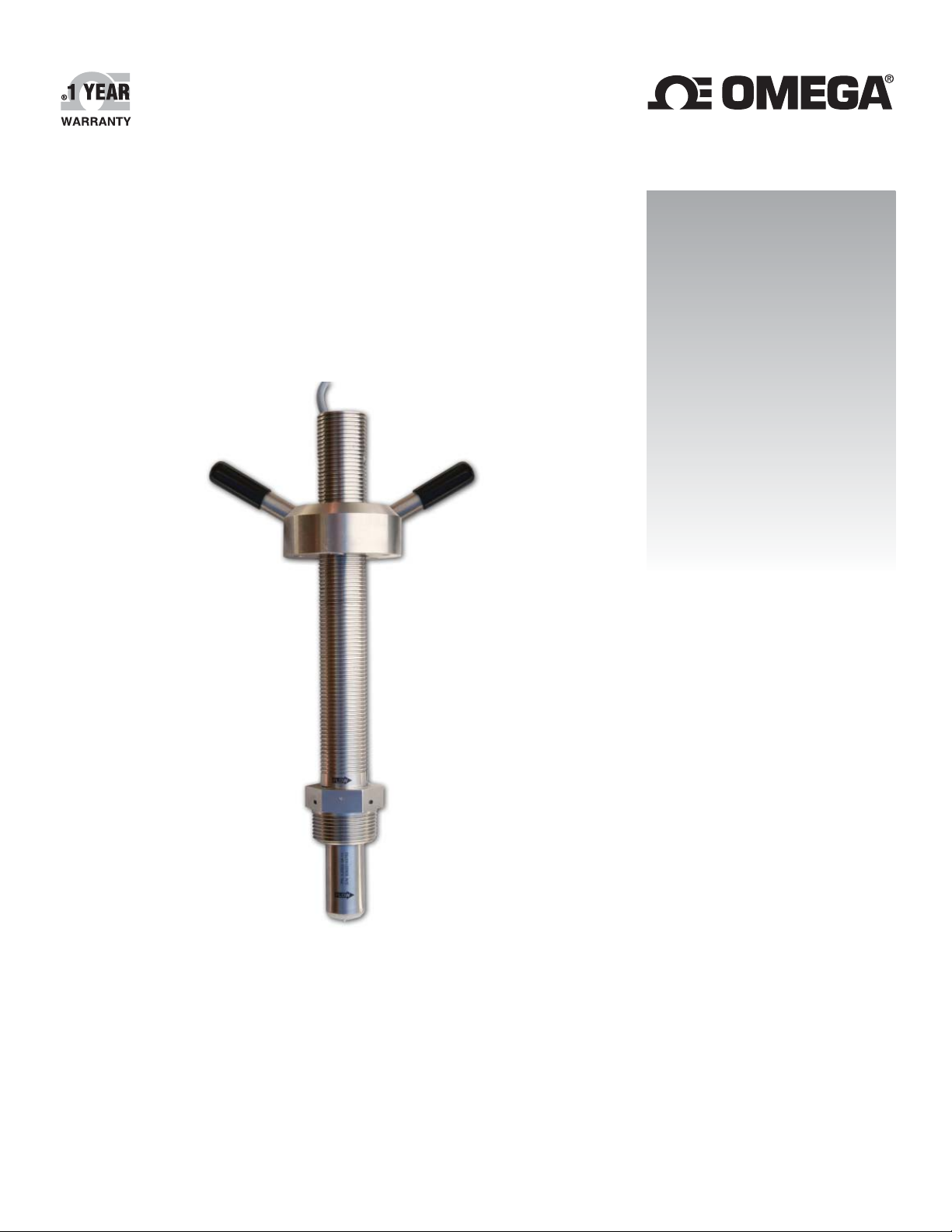
User’s Guide
Shop online at
omega.com
e-mail: [email protected]
For latest product manuals:
www.omegamanual.info
SM
FMG-550 SERIES
OMEGAMAG
Page 2

omega.com [email protected]
Servicing North America:
U.S.A. Omega Engineering, Inc.
Headquarters: Toll-Free: 1-800-826-6342 (USA & Canada only)
Customer Service: 1-800-622-2378 (USA & Canada only)
Engineering Service: 1-800-872-9436 (USA & Canada only)
Tel: (203) 359-1660 Fax: (203) 359-7700
e-mail: [email protected]
For Other Locations Visit omega.com/worldwide
The information contained in this document is believed to be correct, but OMEGA accepts no liability for any errors it contains, and reserves
the right to alter specifications without notice.
Page 3
FMG-550 Series OMEGAMAG
0
SAFETY INSTRUCTIONS
1. Depressurize and vent systems without Hot-tap valve prior to installation or removal.
2. Confi rm chemical compatibility before use.
3. Do not exceed maximum temperature/pressure specifi cations.
4. Wear safety goggles or face shield during installation/service.
5. Do not disassemble or alter product construction.
6. Disconnect power before attempting any service or wiring.
Specifi cations
Wetted Materials:
• 316L Stainless Steel body and electrodes
• PVDF Insulator
• O-rings: FPM standard, EPDM, Perfl uoroelastomer optional
• Cable: 4-cond + shield, PVC jacket (Fixed cable models)
• Watertight rubber cable assembly w/NEMA 6P connector
(Submersible cable models)
Power Requirements
• 4 to 20 mA: 24 VDC nominal, 22.1 mA maximum
(21.6 VDC min. to 26.4 max.)
400 mV pp maximum ripple voltage
• Frequency: 5 to 24 VDC nominal, 15 mA maximum
(5 VDC min. to 26.4 VDC max.)
• Reverse polarity and short circuit protected
Performance
• Pipe size range: 2 in. to 48 in. (DN50 to DN1200)
• Minimum fl ow range 0.05 m/s (0.15 ft/s)
Maximum fl ow range: 10 m/s (33 ft/s)
• Linearity: ±1% reading + 0.1% of max. range
• Repeatability ±0.5% of reading @ 25°C
• Accuracy: ±2% of measured value (in reference
conditions where the fl uid is water at
ambient temperature, the appropriate
upstream and downstream distances
are observed, the sensor is inserted
at the correct depth and there is a
fully developed fl ow profi le which is in
compliance with ISO 7145-1982 (BS
1042 section 2.2)
• Minimum Conductivity: 20 S/cm
Output Specifi cations
Current output (4 to 20 mA)
• Programmable and reversible
• Loop Accuracy: 32 A max. error
(@ 25°C @ 24 VDC)
• Temp. drift: ±1 A per °C max.
• Power supply rejection: ±1 A per V
• Isolation: Low voltage <48 VAC/DC
from electrodes and auxiliary power
• Maximum cable: 300 m (1000 ft.)
• Max. Loop Resistance: 300
• Error condition: 22.1 mA
Frequency output:
• Max. Pull-up Voltage: 30 VDC
• Min. Current Sink: 50 mA
• Max. cable: 300 m (1000 ft.)
• Short Circuit Protected: 30 V @ 0 pull-up for one hour
• Reverse Polarity Protected to -40 V for 1 hour
• Overvoltage Protected to +40 V for 1 hour
Tests, Approvals & Standards
• CE
Environmental
• NEMA 4/IP65 (Fixed cable models only)
• NEMA 6P/IP68 (Submersible cable models only)
• Storage Temperature: -15 to 70 °C (5 to 158 °F)
(non-icing conditions)
• Operating Temperature (non-icing conditions)
Ambient: -15 to 70 °C (5 to 158 °F)
Media: -15 to 85 °C (5 to 185 °F)
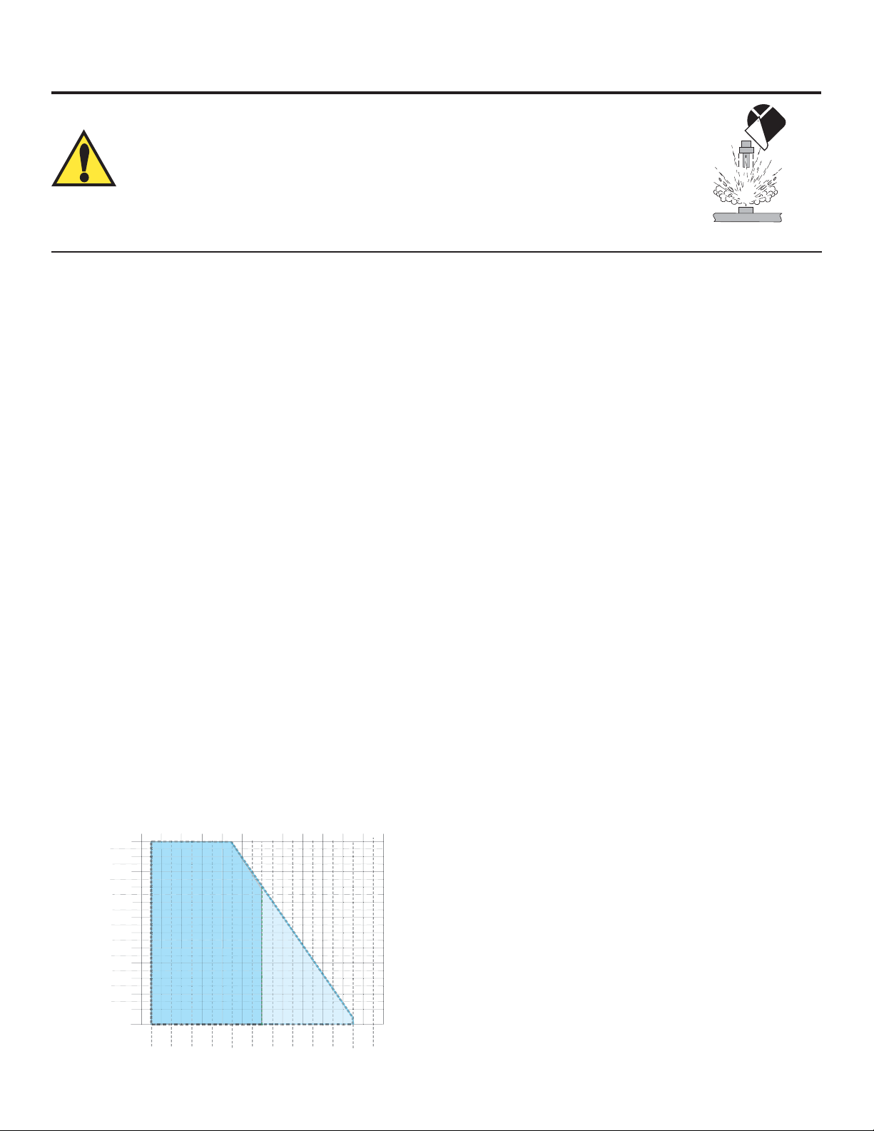
• Max. oper. pressure: 20.6 bar @ 25 °C (300 psi @ 77°F)
bar psi
20.6
300
19.8
275
18.1
250
16.4
225
14.7
200
12.9
175
11. 2
150
9.5
125
7.8
6.0
4.3
2.6
0.9
°C
100
°F
75
50
25
-10
5
23
Safe to operate Hot-tap
Safe Media Pressure
and
Temperature Range
0
10
20-20 30 40 50 60 70 80 90
59 71
95 113 131
41
100
158 185 212
1Omega 550 Series Magmeter
Page 4
Selecting a Location
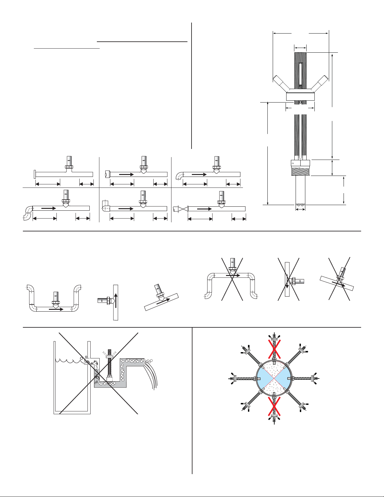
• The FMG-55x requires a fully developed turbulent fl ow profi le
for accurate measurement.
• If the piping system harbors air pockets or bubbles, locate
the sensor so the air pockets will not contact the electrodes.
• New magmeters should be allowed to soak in a full pipe for
24 hours before operation. This is especially important if the
conductivity of the process liquid is less than 100 S.
• FMG-55x Magmeters equipped with the submersible cable
are rated NEMA 6P (IP68). These units can withstand
submersion to depths no greater than 2 m (6 ft.) for
prolonged periods.
• FMG-55x Magmeters with fi xed cables are rated NEMA
4/IP65. They are NOT suitable for submersion.
Dimensions
137 mm
5.14 in.
32 mm
1.25 in.
76 mm
3.0 in.
289 mm
11.4 in.
Select a location with suffi cient distance of straight pipe
immediately upstream of the sensor.
Inlet Outlet
Flange
10 x I.D. 5 x I.D.
2 x 90° Elbow
25 x I.D. 5 x I.D.
+GF+
+GF+
Reducer
15 x I.D. 5 x I.D.
2 x 90° Elbow
3 dimensions
40 x I.D. 5 x I.D.
+GF+
+GF+
90° Elbow
Valve/Pump
Locating the sensor in a trap or where the fl ow is upward helps to
protect the sensor from exposure to air bubbles when the system
is in operation. NOTE: The system should be designed to keep
the sensor wet at all times.
O.K.O.K. O.K.
+
F
G
+
GF
+GF+
+
+
276.3 mm
10.88 in.
+GF+
20 x I.D. 5 x I.D.
+GF+
50 x I.D. 5 x I.D.
1¼ in. NPT
threads
25.4 mm
41 mm
1.6 in.
Stroke length 238 mm/9.38 in.
1.0 in.
These confi gurations are not recommended because it is diffi cult
to keep the pipe full.
+GF+
+
GF
+
+
G
F
+
In a gravity-fl ow system, the tank must be designed so the level
does not drop below the outlet. This causes the pipe to draw
air in from the tank. If air bubbles pass across the Magmeter
electrodes, the output will become erratic.
Mounting the sensor upright is OK only where the pipe is full and
no air pockets are present at the top of the pipe.
Mount at a maximum of 45° when air bubbles are present.
Do not mount on the bottom of the pipe if sediments are present.
2 Omega 550 Series Magmeter
Page 5
Standard Magmeter Installation
The following items are required to properly install the Magmeter:
• Supplied with FMG-553 and FMG-554 Magmeters:
• Ruler
• Brass alignment rod
• H-dimension value for your pipe (See pages 9-10)
• Hex wrench
• 2 clamp rings
• Grounding screw
• Not supplied:
• Female pipe fi tting (weld-on or saddle)
with 1¼ in. NPT threads
• 32 mm (1¼ in.) diameter drill bit
• 32 mm (1¼ in.) pipe nipple
• Pipe thread sealant suitable for application
• Pipe wrench
• Anti-Seize Lubercant for Stainless Steel
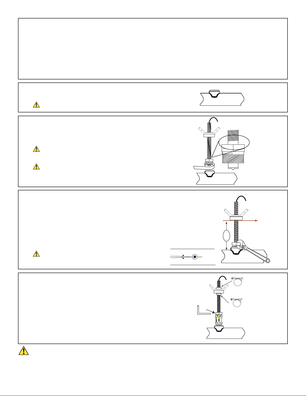
1. Prepare the pipe:
• Cut a 1¼ in. opening in the pipe.
• Install a 1¼ inch outlet onto the pipe.
This fi tting must withstand pressures up to 20 bar (300 psi).
2. Install the Magmeter into the pipe
• Apply sealing tape or paste to the male threads of the sensor nut and
thread it securely into the pipe fi tting.
The sensor is marked to identify the downstream alignment.
The arrow MUST point DOWNSTREAM.
FLOW →
Wear gloves to grip the sensor. Hold the sensor securely while
threading the sensor nut into the fi tting. Do not allow the magmeter
cable to become twisted while turning the nut.
3. Adjust the magmeter position and insertion depth
• Find the H-dimension for your specifi c pipe size on pages 7-8.
• Insert the brass rod through the alignment opening at the top of
the sensor.
• Lubricate the threaded sensor housing with the anti-seize
lubricant supplied.
• Adjust the height of the magmeter so the distance (H) from the
OUTSIDE of the pipe to the bottom of the alignment rod is equal
to the H-dimension.
• Adjust the alignment rod so it is parallel to the pipe ±1°.
Misalignment will cause inaccurate measurement.
• If necessary, re-apply a suitable lubricant to the threaded sensor
housing to facilitate smooth operation.
4. Secure the Magmeter in position
• Secure the fi tting by tightening the set screw on the side of the sensor
assembly. A set screw wrench is provided in the magmeter package.
• Secure the height adjustment by installing the two pipe clamps.
• Spread the clamp apart to wrap it around the threaded stem.
• Place one clamp immediately above and one clamp immediately
below the magmeter adjustment hub.
• Squeeze the clamp together until it is fi rmly locked around the
threads.
Pipe Top View
Align Magmeter with pipe ±1°
Set Screw
Set Screw
Wrench
FLOW →
H
FLOW →
FLOW →
WARNING!
• Dry operation under high fl uid pressure may cause permanent damage to this device.
FLOW →
3Omega 550 Series Magmeter
Page 6
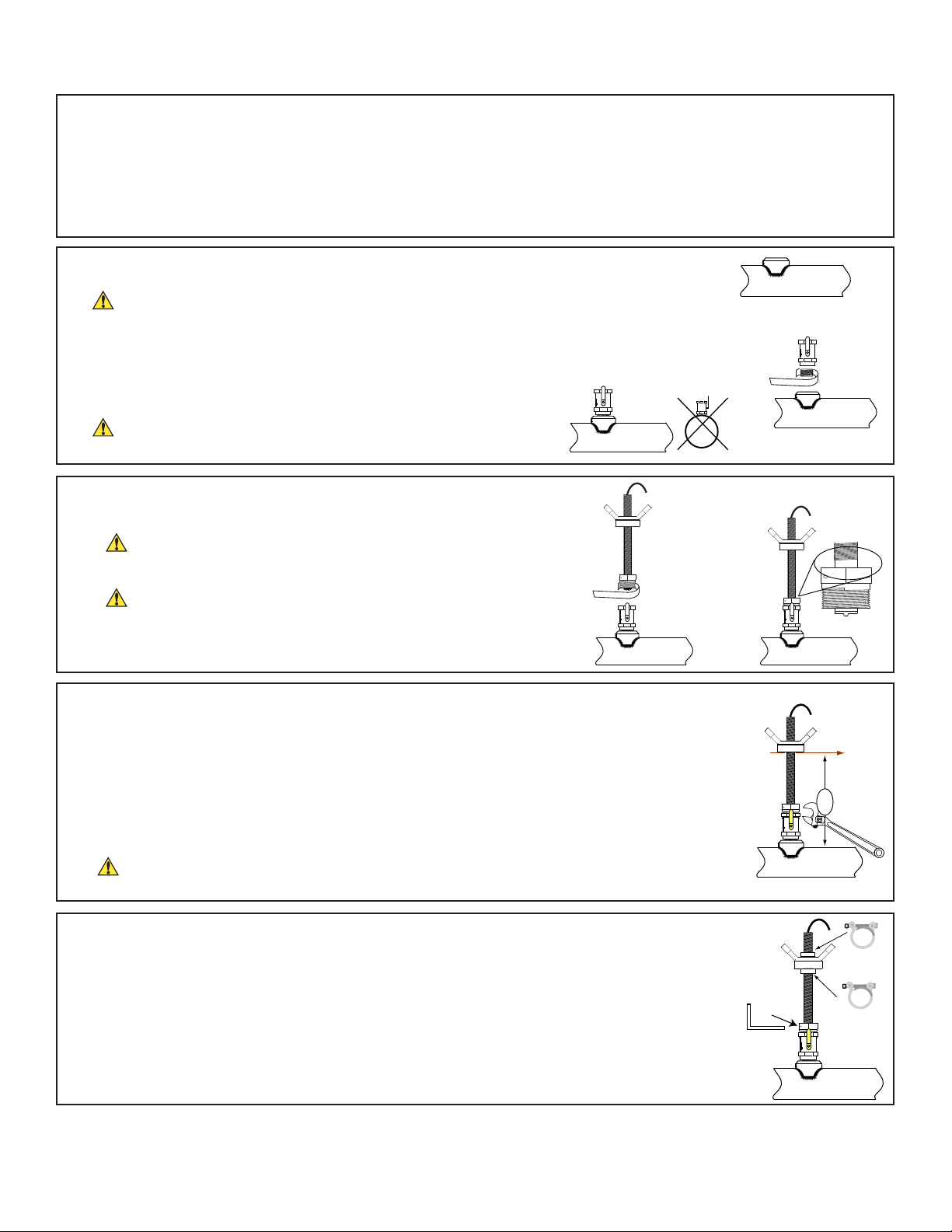
Hot-tap Magmeter Installation
The following items are required to properly install the Magmeter through a Hot-tap valve:
• Supplied with FMG-553 and FMG-554 Magmeters:
• Ruler
• Brass alignment rod
• Allen wrench
• 2 clamp rings
• H-dimension value for your pipe (See pages 7-8)
• Grounding screw
• Anti-Seize Lubercant for Stainless Steel
• Not supplied:
• Female pipe fi tting (weld-on or saddle)
with 1¼ in. NPT threads
• 32 mm (1¼ in.) pipe nipple
• 32 mm (1¼ in.) ball valve
• 32 mm (1¼ in.) diameter drill bit
• Pipe thread sealant suitable for application
• Pipe wrench
1. Prepare the pipe:
• Install a 1¼ inch outlet onto the pipe.
This fi tting must withstand pressures up to 20 bar (300 psi).
• Thread the 1¼ in. pipe nipple into the outlet. Use a suitable paste or sealing tape to provide a
leakproof connection.
• Thread the 1¼ in. ball valve onto the pipe nipple.
Position the valve handle so it is parallel to the pipe. This will prevent the valve handle from
interfering with the adjustment and alignment of the magmeter.
• Cut a 1¼ in. opening in the pipe.
Hot- tap drilling requires special tools and skills.
This task should only be performed by qualifi ed personnel.
FLOW →
2. Install the Magmeter into the pipe
• Apply sealing tape or paste to the male threads of the sensor nut and
thread it securely into the pipe fi tting.
The sensor is marked to identify the downstream alignment. The
arrow MUST point DOWNSTREAM.
Wear gloves to grip the sensor. Hold the sensor securely while
threading the sensor nut into the fi tting. Do not allow the magmeter
cable to become twisted while turning the nut.
FLOW →
FLOW →
FLOW →
FLOW →
3. Adjust the magmeter position and insertion depth
• Find the H-dimension for your specifi c pipe size on pages 7-8.
• Insert the brass rod through the alignment opening at the top of the sensor.
• IMPORTANT! Apply Anti-Seize Lubricant for stainless steel ("Permatex" brand or equivalent) to the
acme threads on the housing. Apply fresh lubricant whenever servicing and before retracting sensor.
Dry operation under high fl uid pressure may cause permanent damage!
• Adjust the height of the magmeter so the distance (H) from the OUTSIDE of the pipe to the bottom of
the alignment rod is equal to the H-dimension.
• Adjust the alignment rod so it is parallel to the pipe ±1°.
Misalignment will cause inaccurate measurement.
• If necessary, re-apply a suitable lubricant to the threaded sensor housing to facilitate smooth operation.
4. Secure the Magmeter in position
• Secure the fi tting by tightening the set screw on the side of the sensor assembly. A set screw
wrench is provided in the magmeter package.
• Secure the height adjustment by installing the two pipe clamps:
• Spread the clamp apart to wrap it around the threaded stem.
• Place one clamp immediately above and one clamp immediately below the magmeter
adjustment hub.
• Squeeze the clamp together until it is fi rmly locked around the threads.
Set Screw
Set Screw
Wrench
H
FLOW →
FLOW →
4 Omega 550 Series Magmeter
Page 7
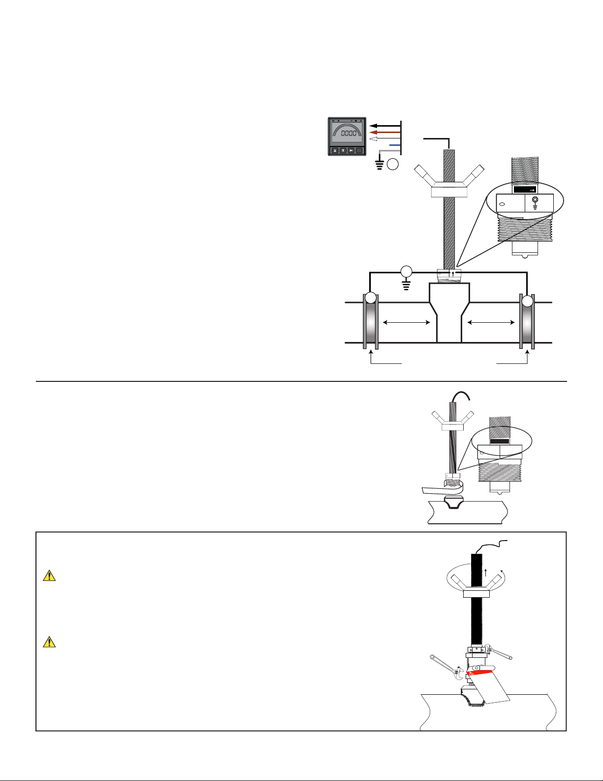
General Installation and Grounding Tips
Sensor conditioning
The Magmeter output signal may be unstable immediately after installation. Allowing the sensor to soak in a full pipe (or in any
container of water) for 24 hours will stabilize the performance.
• Very low conductivity fl uids may require a longer conditioning period. (The Magmeter may not operate properly in fl uids where the
conductivity is less than 20 S/cm.)
Grounding
The FMG-55x Magmeter is unaffected by moderate levels of electrical
noise, especially if installed in a properly grounded metal piping system.
However, in some applications it may be necessary to ground portions
of the system to eliminate electrical interference. The grounding
requirements will vary with each installation.
One or more of the following steps may be applied if the Magmeter is
affected by electrical noise:
Connect a wire (14 AWG/2.08 mm
2
recommended) from the ground
terminal screw on the outside of the sensor nut directly to a local
Earth ground.
Install fl uid grounding devices immediately upstream and downstream
of the Magmeter.
Connect the fl uid grounds to the Earth ground terminal on the
FMG-55x.
Use fl anged grounding rings or metal electrodes on plastic pipes, or
metal clamps on metal pipes.
Fluid grounds must be in direct contact with the fl uid, and as near to
the Magmeter as possible.
Connect the SHIELD conductor to Earth ground at the instrument.
Bi-Directional Flow
ENTER
DPU91
See page 6 for
*
wiring details.
2
Black
Brown
White
Blue
Shield
*
3
1
10 cm to 1.3 m
(4 in. to 50 in.)
Grounding rings on plastic pipe
(Installed between flanges)
FLOW ĺ
2
10 cm to 1.3 m
(4 in. to 50 in.)
The FMG-55x magmeter is designed to measure bi-directional fl ow.
• 4-20 mA output models: May be scaled to span any fl ow range:
For example: "4 to 20 mA = -100 GPM to +100 GPM"
• Frequency output models: Reverse fl ow is processed same as forward fl ow.
• The forward fl ow direction is indicated at the base of the sensor. The arrow must point
DOWNSTREAM.
Removal Instructions
REDUCE THE PROCESS TEMPERATURE TO LESS THAN 40 °C (104 °F)
• Remove the plastic clamp from the top of the assembly.
• Turn the sensor nut to the top of the threads to retract the sensor.
A light lubricant can be applied to the threads if required.
• Close the valve.
Install a LOCKOUT TAG on the closed valve to prevent accidents!
• Remove the magmeter from the top of the valve.
• Loosen the set screw from the sensor adapter fi tting.
• Use one pipe wrench to hold the valve in place while turning the sensor adapter with
a second wrench.
FLOW →
HOLD VALVE IN PLACE!
FLOW→
Turn magmeter adapter ONLY!
CLOSE VALVE
BEFORE REMOVING MAGMETER!
DANGER!
DO NOT
OPEN
THIS VALVE
This lock/tag may
only be removed by:
Name ___________
Dept. ____________
Expected date for
completion: _________
UNDER PRESSURE!
5Omega 550 Series Magmeter
Page 8
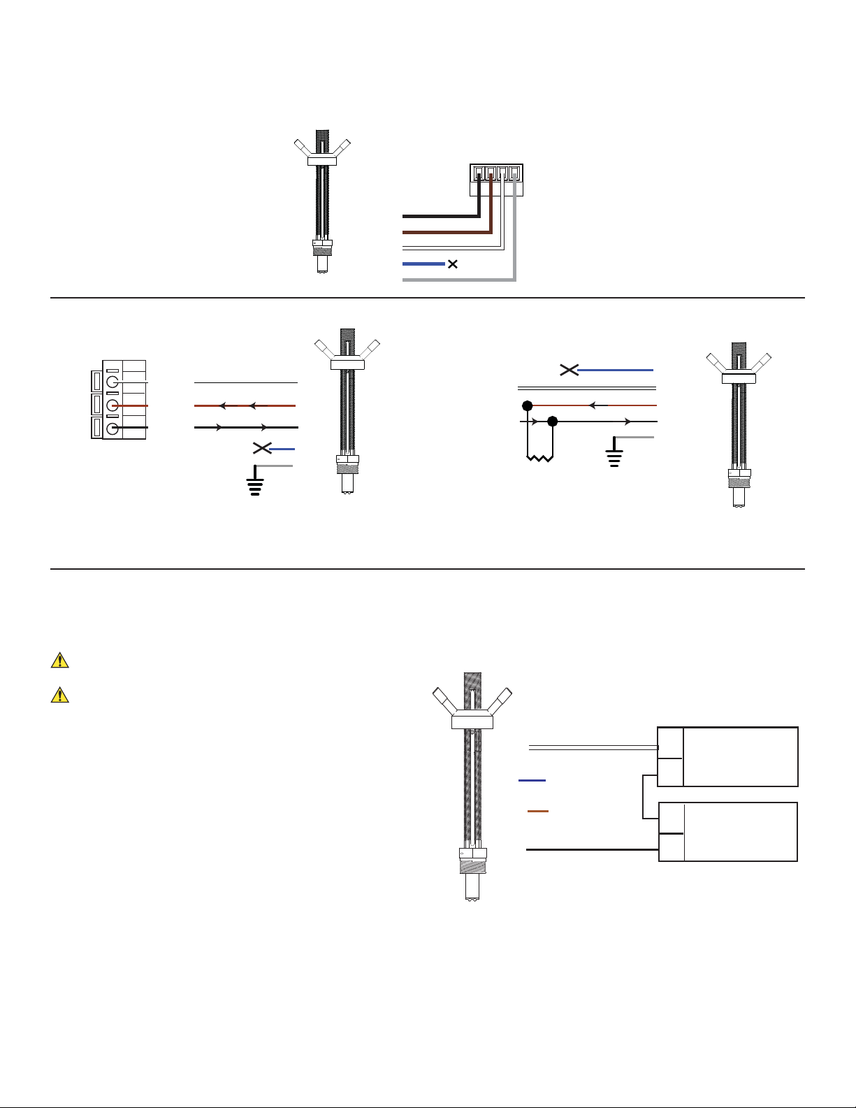
Wiring the FMG 553 with Frequency Output
Wiring: Frequency Output
Black
Brown
White
Blue
Shield
DPU91 Frequency
Wiring
SHLD
DATA
GND
V+
No
connection
FP-90 Series Flow Transmitter
Sensr Gnd
(SHIELD)
Sensr IN
(RED)
Sensr V+
(BLACK)
White
Brown
Black
Blue
Shield
Connect AUX power on the FP-90 to provide
Third party Instrument
Sensor Ground
Frequency Out
5-24 VDC
Install a pull-up resistor when connecting
the FMG-55x Magmeter to other
manufacturer's flowmeters.
power for the FMG-55x output signal.
Wiring the FMG-554 with 4-20 mA Loop Output
The FMG-554 Magmeter is a traditional 2-wire passive 4-20 mA loop transmitter.
• External loop power (24 VDC ±10%) is required.
The maximum loop resistance the Magmeter can
accomodate is 300 Ω.
The cable length from the Magmeter to the loop monitor
cannot exceed 300 m (1000 ft.)
• All FMG-55x Magmeters are shipped from the factory
with the 4-20 mA output scaled for 0 to 5 m/s (0 to 16.4
ft/s). If this operating range is suitable, no adjustments are
necessary. The calibration charts in this manual list the
20 mA setpoint for each pipe size. Use this information
to program the 4-20 mA range of the loop device (PLC,
Datalogger, recorder, etc.)
10 KΩ
FMG-55x Magmeter
White
Blue
Loop - (Ground)
X
Brown X
Black
Loop + (24 VDC)
Blue
White
Brown
Black
Shield
4-20 mA Loop
+
-
monitor
(Maximum 300 Ω)
24 VDC ± 10%
+
6 Omega 550 Series Magmeter
Page 9
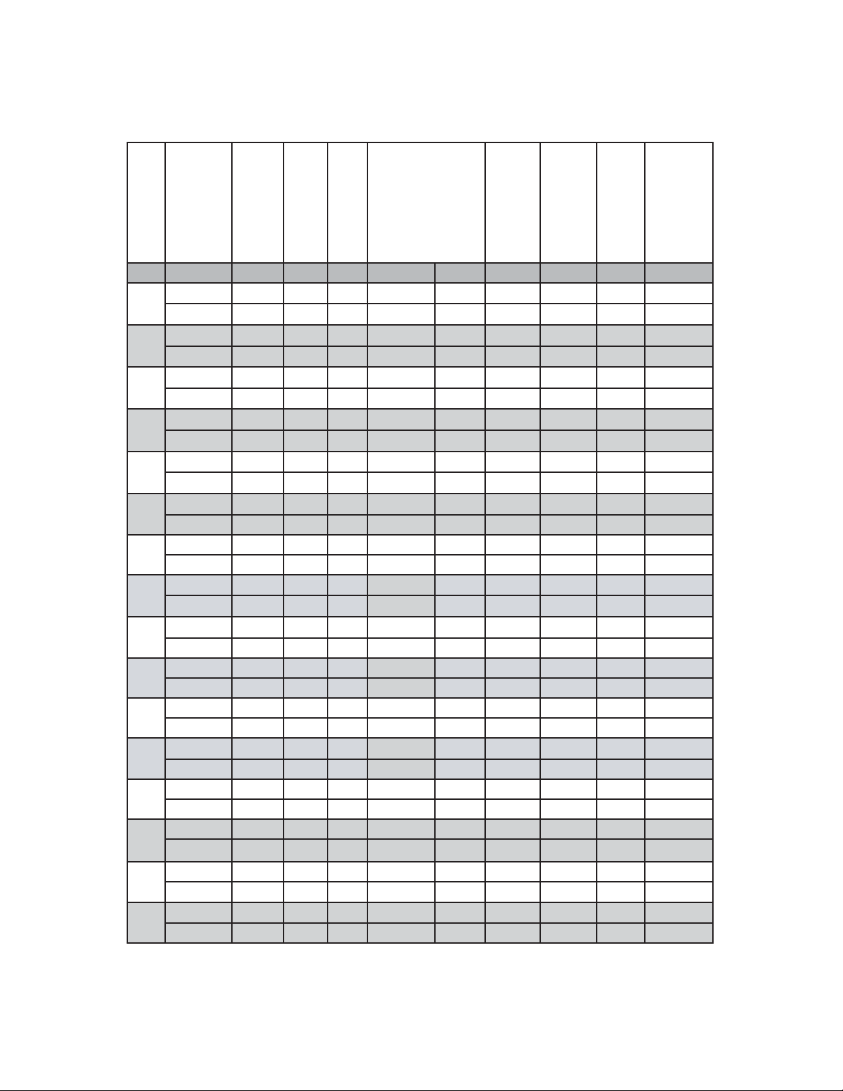
Calibration Data: K-factors and Full Scale Current Values
The data in this table is based on dimensions of metal pipe per ANSI 36.10 and ANSI 36.19.
Stainless steel and carbon steel pipe schedules are the same according to ANSI standards.
Pipe Size (ANSI)
2
2½
3
3½
4
5
6
8
10
12
14
16
18
20
22
24
Schedule
40 2.375 0.15 2.07 16 5/32 409.9 46.19 174.83 649.5 171.6
80 2.375 0.22 1.94 16 3/32 408.6 52.49 198.68 571.5 151.0
40 2.875 0.20 2.47 16 407.7 32.37 122.54 926.7 244.8
80 2.875 0.28 2.32 16 406.2 36.57 138.42 820.3 216.7
40 3.500 0.22 3.07 15 31/32 405.8 20.97 79.36 1431 378.0
80 3.500 0.30 2.90 15 29/32 404.1 23.47 88.82 1278 337.8
40 4.000 0.23 3.55 15 29/32 404.4 15.68 59.34 1914 505.6
80 4.000 0.32 3.36 15 27/32 402.5 17.44 66.01 1720 454.5
40 4.500 0.24 4.03 15 28/32 402.9 12.18 46.09 2464 651.0
80 4.500 0.34 3.83 15 25/32 400.9 13.48 51.03 2225 587.9
40 5.563 0.26 5.05 15 24/32 399.7 7.748 29.33 3872 1023
80 5.563 0.38 4.81 15 21/32 397.4 8.519 32.25 3521 930.4
40 6.625 0.28 6.07 15 20/32 396.6 5.365 20.31 5591 1477
80 6.625 0.43 5.76 15 16/32 393.5 5.946 22.51 5045 1333
40 8.625 0.32 7.98 15 12/32 390.7 3.098 11.73 9683 2558
80 8.625 0.50 7.63 15 8/32 387.0 3.394 12.85 8838 2335
40 10.75 0.37 10.0 15 4/32 384.4 1.966 7.440 15262 4032
80 10.75 0.59 9.56 14 30/32 379.8 2.158 8.170 13899 3672
STD 12.75 0.38 12.0 14 30/32 379.1 1.371 5.187 21890 5783
XHY 12.75 0.50 11.8 14 26/32 376.6 1.429 5.410 20987 5545
30 14.00 0.38 13.3 14 26/32 375.9 1.124 4.255 26688 7051
XHY 14.00 0.50 13.0 14 22/32 373.4 1.168 4.420 25690 6787
30 16.00 0.38 15.3 14 19/32 370.8 0.849 3.212 35352 9340
40/XHY 16.00 0.50 15.0 14 16/32 368.3 0.877 3.320 34202 9036
STD 18.00 0.38 17.3 14 13/32 365.8 0.663 2.510 45233 11950
XHY 18.00 0.50 17.0 14 10/32 363.2 0.683 2.585 43931 11610
20/STD 20.00 0.38 19.3 14 6/32 360.7 0.533 2.016 56330 14880
30/XHY 20.00 0.50 19.0 14 3/32 358.1 0.547 2.069 54876 14500
20/STD 22.00 0.38 21.3 14 355.6 0.437 1.654 68643 18136
30/XHY 22.00 0.50 21.0 13 29/32 353.1 0.448 1.694 67037 17711
20/STD 24.00 0.38 23.3 13 26/32 350.5 0.365 1.382 82172 21710
XHY 24.00 0.50 23.0 13 22/32 348.0 0.373 1.412 80414 21246
OD (Inches)
WALL (Inches)
ID (Inches)
Inch mm
H Dim mm
FMG-553
FMG-554
K-Factor
Pulse/liter
K-Factor
Pulse/Gal
Factory set
20 mA (liter/min)
Factory set20
mA (GPM)
7 Omega 550 Series Magmeter
Page 10
Pipe Size (ANSI)
Schedule
OD (Inches)
WALL (Inches)
ID (Inches)
H Dim mm
FMG-553
FMG-554
K-Factor
Pulse/liter
K-Factor
Pulse/Gal
Factory set
Inch mm
26
28
30
32
34
36
38
40
42
48
STD 26 0.38 25.25 13 19/32 345.4 0.310 1.172 96917 25606
20/XHY 26 0.50 25.00 13 16/32 342.9 0.316 1.195 95008 25101
STD 28 0.38 27.25 13 13/32 340.4 0.266 1.006 112879 29823
20/XHY 28 0.50 27.00 13 10/32 337.8 0.271 1.025 110817 29278
STD 30 0.38 29.25 13 6/32 335.3 0.231 0.873 130056 34361
20/XHY 30 0.50 29.00 13 3/32 332.7 0.235 0.888 127842 33776
STD 32 0.38 31.25 13 330.2 0.202 0.765 148449 39220
20/XHY 32 0.50 31.00 12 29/32 327.7 0.205 0.777 146084 38595
STD 34 0.38 33.25 12 26/32 325.1 0.179 0.676 168059 44401
20/XHY 34 0.50 33.00 12 22/32 322.6 0.181 0.686 165541 43736
STD 36 0.38 35.25 12 19/32 320.0 0.159 0.601 188885 49903
20/XHY 36 0.50 35.00 12 16/32 317.5 0.161 0.610 186215 49198
STD 38 0.38 37.25 12 13/32 315.0 0.142 0.538 210926 55727
XHY 38 0.50 37.00 12 10/32 312.4 0.144 0.546 208105 54981
STD 40 0.38 39.25 12 6/32 309.9 0.128 0.485 234184 61872
XHY 40 0.50 39.00 12 3/32 307.3 0.130 0.491 231210 61086
STD 42 0.38 41.25 12 304.8 0.116 0.439 258658 68338
XHY 42 0.50 41.00 11 29/32 302.3 0.117 0.444 255532 67512
STD 48 0.38 47.25 11 13/32 289.6 0.088 0.335 339377 89664
XHY 48 0.50 47.00 10 26/32 274.32 0.089 0.338 335795 88717
20 mA (liter/min)
Factory set
20 mA (GPM)
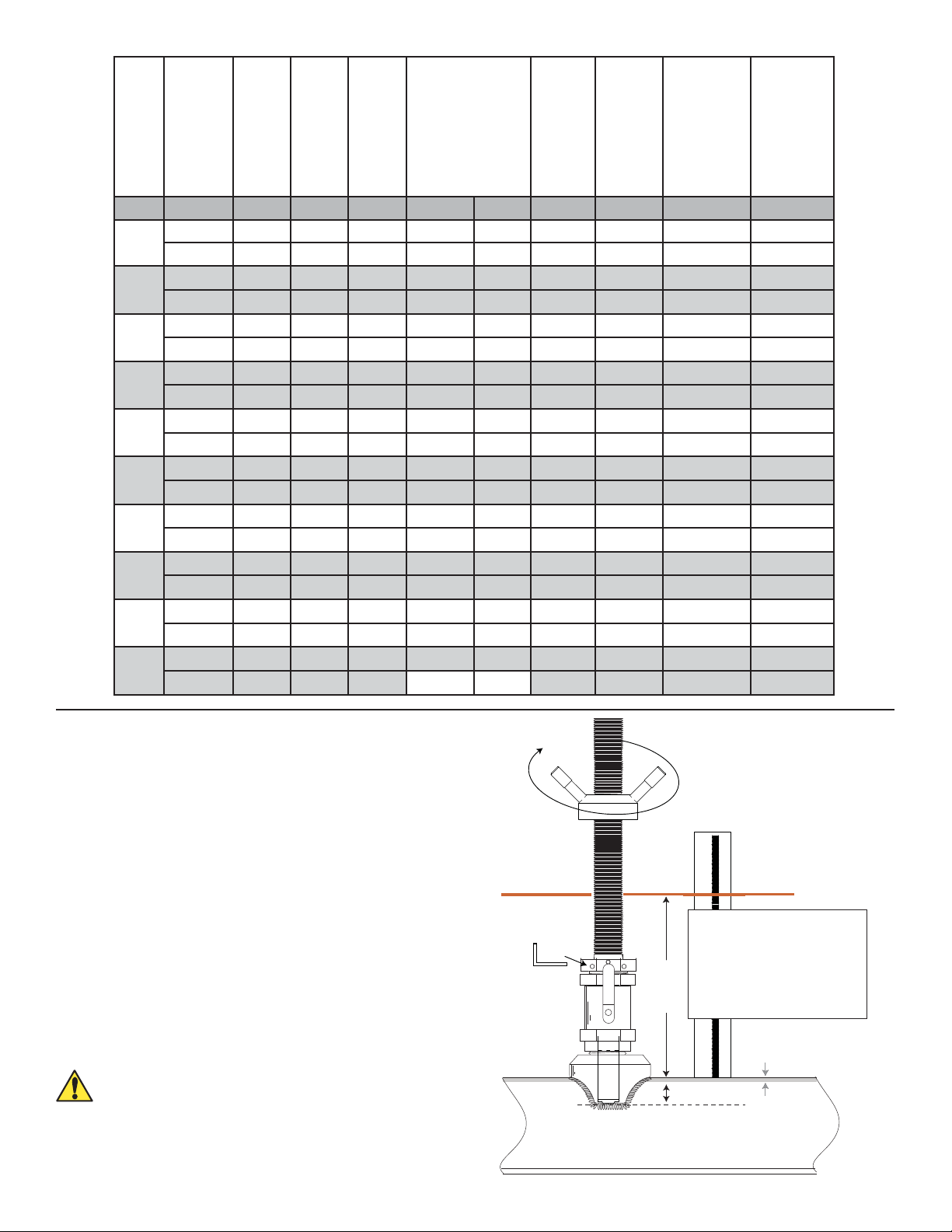
Installation instructions for other pipes
If your pipe is not listed in the tables, you can calculate the proper
H-dimension as illustrated here.
Contact the factory for a custom K-Factor.
Height from the sensor tip to the alignment rod is:
FMG-553, -554: 276.3 mm ( 10.88 in. )
Subtract:
- Wall Thickness: _____ mm ( ______ in.)
Subtract:
- 10% of pipe id: _____ mm ( ______ in.)
Result:
= H dimension: _____ mm ( ______ in.)
Note: 1 in. = 25.4 mm
Hardware stack height is important
The H-dimension represents the total height available for
the installation hardware.
If there is insuffi cient clearance to accommodate the
hardware, select a longer 2552 Magmeter or modify the
hardware to reduce the stack height.
Set Screw
Set Screw
Wrench
UNDER PRESSURE!
mm
270
260
250
240
230 220
210
200 190
Sensor Height:
180 170
FMG-553, -554: 276.3 mm ( 10.88 in. )
H DIMENSION
Subtract:
160 150 140
- Wall Thickness: _____ mm ( ______ in.)
- 10% of pipe id: _____ mm ( ______ in.)
130
Result:
120
110
= H dimension: _____ mm ( ______ in.)
H
100
Note: 1 in. = 25.4 mm
90
80
70
60 50 40
10% of
inside diameter
Wall Thickness
8Omega 550 Series Magmeter
Page 11
Maintenance
There are no user-serviceable components in the FMG series Magmeter.
• If the fl uid contains deposits and solids that may coat the electrodes, a regular cleaning schedule is recommended.
• Do not use abrasive materials on the metal electrodes. Clean with soft cloth and mild detergent only.
• Use a cotton swab and mild detergent to remove deposits on the metal electrodes at the tip of the sensor.
• If the sensor nut will not turn smoothly, a light lubricant can be applied to the threads.
Environmental Recommendations:
• When used properly, this product presents no inherent danger to the environment.
• Please follow local ordinance when disposing of this or any product with electronic components.
Troubleshooting
Symptom Possible Cause Possible Solution
• Frequency output or Current
output is erratic.
• Output is not 0 when fl ow is stopped.
• 4-20 mA output is incorrect.
• Magmeter installed too close to
upstream obstruction.
• Magmeter electrodes are coated with
solids.
• Magmeter electrodes exposed to air
bubbles/pockets.
• Electrical noise is interfering with the
measurement.
• New sensor, metal surface not
properly conditioned.
• Electrodes not adequately conditioned.
• Pipe is empty, Magmeter is not in fl uid.
• Electrical noise is interfering with the
measurement.
• Defective Magmeter
• Magmeter 4-20 mA is not scaled
same as Loop device.
• Loop device is not scaled same as
Magmeter.
• Defective Magmeter
• Move the Magmeter upstream at least
10 pipe diameters from obstruction.
• Clean the electrodes with soft cloth.
Do not use abrasives.
• Eliminate air bubbles in the pipe.
• Remove the Magmeter and reinstall
with the fl ow direction arrow on the
sensor body pointed DOWNSTREAM.
• Modify grounding as required
to protect the Magmeter from
interference.
• Soak sensor overnight in fl uid.
• Soak sensor overnight in fl uid.
• Confi gure pipe so electrodes are
always in fl uid.
• Modify grounding as required
to protect the Magmeter from
interference.
• Return to factory for service.
• Respan the Magmeter to match the
Loop device.
• Respan Loop device to match
Magmeter.
• Return to factory for service.
• Frequency output is inoperative
• Loop output is inperative.
• Wiring is not correct.
• Frequency input to other
• Check wiring, make corrections.
• Install 10k resistor.
manufacturer's fl ow instrument does
not have pull-up resistor.
• Output is 22.1 mA.
• Conductivity is less than 20 S/cm.
• Electrical noise
• Electronic component failure.
• Unsuitable application for Magmeter.
• Check grounding, eliminate noise
source.
• Return to factory for service.
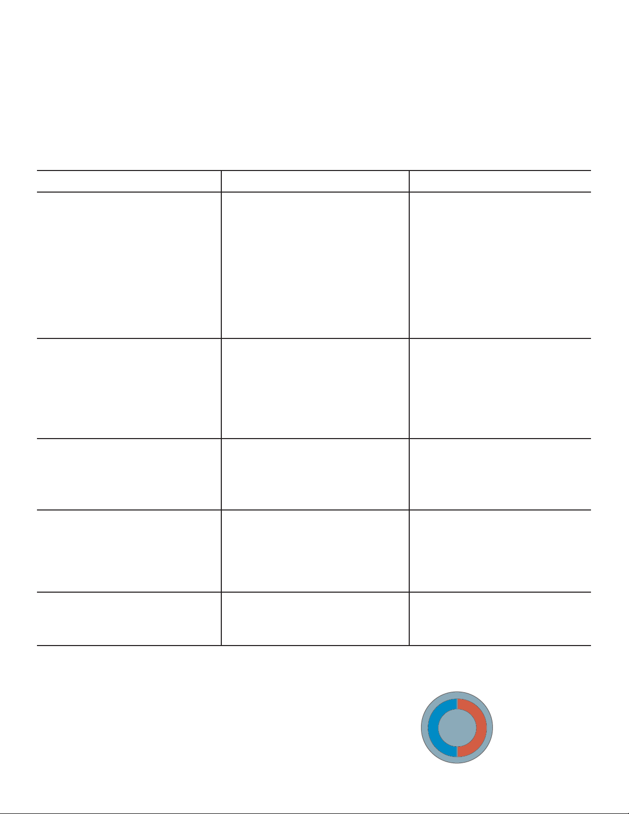
Troubleshooting with the RED and BLUE lights
The FMG-55x uses two colored LEDs to indicate the status of the measurement. They are located at the top of the magmeter, recessed
inside the threaded steel housing. Look down the tube to see them.
No Lights: The power is off or the sensor is not connected
Solid Blue: The power is on but there is no fl ow in the pipe.
Blinking Blue: Normal operation, blink rate is proportional to the fl ow rate.
e
u
l
B
Alternating Red-Blue: Empty pipe indication (electrodes are not wet.)
Blinking Red: System errors (electrical noise interference)
Solid Red: Instrument error (defective electronics component)
9 Omega 550 Series Magmeter
R
e
d
Page 12

Ordering Information
Part No. Description
FMG-553 9.3 in. Sensor protrusion depth, Hot-tap, 1¼ in. NPT, Fixed Cable, Frequency Output
FMG-554 9.3 in. Sensor protrusion depth, Hot-tap, 1¼ in. NPT, Fixed Cable, 4 to 20 mA Output
FMG-553-SUB 9.3 in. Sensor protrusion depth, Hot-tap, 1¼ in. NPT, Connector, Frequency Output
FMG-554-SUB 9.3 in. Sensor protrusion depth, Hot-tap, 1¼ in. NPT, Connector, 4 to 20 mA Output
FMG-550-S-CABLE 4-conductor, 22 AWG, water-tight connector, 6m (19.5 ft.) for -SUB models
Page 13

Notes
11 Omega 550 Series Magmeter
Page 14

Notes
12 Omega 550 Series Magmeter
Page 15

WARRANTY/DISCLAIMER
OMEGA ENGINEERING, INC. warrants this unit to be free of defects in materials and workmanship for a
period of 13 months from date of purchase. OMEGA’s WARRANTY adds an additional one (1) month
grace period to the normal one (1) year product warranty to cover handling and shipping time. This
ensures that OMEGA’s customers receive maximum coverage on each product.
If the unit malfunctions, it must be returned to the factory for evaluation. OMEGA’s Customer Service
Department will issue an Authorized Return (AR) number immediately upon phone or written request.
Upon examination by OMEGA, if the unit is found to be defective, it will be repaired or replaced at no
charge. OMEGA’s WARRANTY does not apply to defects resulting from any action of the purchaser,
including but not limited to mishandling, improper interfacing, operation outside of design limits,
improper repair, or unauthorized modification. This WARRANTY is VOID if the unit shows evidence of
having been tampered with or shows evidence of having been damaged as a result of excessive corrosion;
or current, heat, moisture or vibration; improper specification; misapplication; misuse or other operating
conditions outside of OMEGA’s control. Components in which wear is not warranted, include but are not
limited to contact points, fuses, and triacs.
OMEGA is pleased to offer suggestions on the use of its various products. However,
OMEGA neither assumes responsibility for any omissions or errors nor assumes liability for
any damages that result from the use of its products in accordance with information provided
by OMEGA, either verbal or written. OMEGA warrants only that the parts manufactured by the
company will be as specified and free of defects. OMEGA MAKES NO OTHER WARRANTIES OR
REPRESENTATIONS OF ANY KIND WHATSOEVER, EXPRESSED OR IMPLIED, EXCEPT THAT OF
TITLE, AND ALL IMPLIED WARRANTIES INCLUDING ANY WARRANTY OF MERCHANTABILITY
AND FITNESS FOR A PARTICULAR PURPOSE ARE HEREBY DISCLAIMED. LIMITATION OF
LIABILITY: The remedies of purchaser set forth herein are exclusive, and the total liability of
OMEGA with respect to this order, whether based on contract, warranty, negligence,
indemnification, strict liability or otherwise, shall not exceed the purchase price of the
component upon which liability is based. In no event shall OMEGA be liable for
consequential, incidental or special damages.
CONDITIONS: Equipment sold by OMEGA is not intended to be used, nor shall it be used: (1) as a “Basic
Component” under 10 CFR 21 (NRC), used in or with any nuclear installation or activity; or (2) in medical
applications or used on humans. Should any Product(s) be used in or with any nuclear installation or
activity, medical application, used on humans, or misused in any way, OMEGA assumes no responsibility
as set forth in our basic WARRANTY/DISCLAIMER language, and, additionally, purchaser will indemnify
OMEGA and hold OMEGA harmless from any liability or damage whatsoever arising out of the use of the
Product(s) in such a manner.
RETURN REQUESTS/INQUIRIES
Direct all warranty and repair requests/inquiries to the OMEGA Customer Service Department.
BEFORE RETURNING ANY PRODUCT(S) TO OMEGA, PURCHASER MUST OBTAIN AN AUTHORIZED
RETURN (AR) NUMBER FROM OMEGA’S CUSTOMER SERVICE DEPARTMENT (IN ORDER TO AVOID
PROCESSING DELAYS). The assigned AR number should then be marked on the outside of the return
package and on any correspondence.
The purchaser is responsible for shipping charges, freight, insurance and proper packaging to prevent
breakage in transit.
FOR WARRANTY RETURNS, please have the
following information available BEFORE contacting
OMEGA:
1. Purchase Order number under which the product
was PURCHASED,
2. Model and serial number of the product under
warranty, and
3. Repair instructions and/or specific problems
relative to the product.
OMEGA’s policy is to make running changes, not model changes, whenever an improvement is possible. This affords
our customers the latest in technology and engineering.
OMEGA is a registered trademark of OMEGA ENGINEERING, INC.
© Copyright 2016 OMEGA ENGINEERING, INC. All rights reserved. This document may not be copied, photocopied,
reproduced, translated, or reduced to any electronic medium or machine-readable form, in whole or in part, without the
prior written consent of OMEGA ENGINEERING, INC.
FOR NON-WARRANTY REPAIRS,
OMEGA for current repair charges. Have
the following information available BEFORE
contacting OMEGA:
1. Purchase Order number to cover the COST
of the repair,
2. Model and serial number of the product, and
3. Repair instructions and/or specific problems
relative to the product.
consult
Page 16

Where Do I Find Everything I Need for
Process Measurement and Control?
OMEGA…Of Course!
Shop online at omega.com
TEMPERATURE
Thermocouple, RTD & Thermistor Probes, Connectors, Panels & Assemblies
Wire: Thermocouple, RTD & Thermistor
Calibrators & Ice Point References
Recorders, Controllers & Process Monitors
Infrared Pyrometers
PRESSURE, STRAIN AND FORCE
Transducers & Strain Gages
Load Cells & Pressure Gages
Displacement Transducers
Instrumentation & Accessories
FLOW/LEVEL
Rotameters, Gas Mass Flowmeters & Flow Computers
Air Velocity Indicators
Turbine/Paddlewheel Systems
Totalizers & Batch Controllers
SM
pH/CONDUCTIVITY
pH Electrodes, Testers & Accessories
Benchtop/Laboratory Meters
Controllers, Calibrators, Simulators & Pumps
Industrial pH & Conductivity Equipment
DATA ACQUISITION
Communications-Based Acquisition Systems
Data Logging Systems
Wireless Sensors, Transmitters, & Receivers
Signal Conditioners
Data Acquisition Software
HEATERS
Heating Cable
Cartridge & Strip Heaters
Immersion & Band Heaters
Flexible Heaters
Laboratory Heaters
ENVIRONMENTAL
MONITORING AND CONTROL
Metering & Control Instrumentation
Refractometers
Pumps & Tubing
Air, Soil & Water Monitors
Industrial Water & Wastewater Treatment
pH, Conductivity & Dissolved Oxygen Instruments
M-4416/0916
 Loading...