

Page 1
User’s Guide
TM
Shop online at
omega.com
e-mail: [email protected]
For latest product manuals:
omega.com/en-us/pdf-manuals
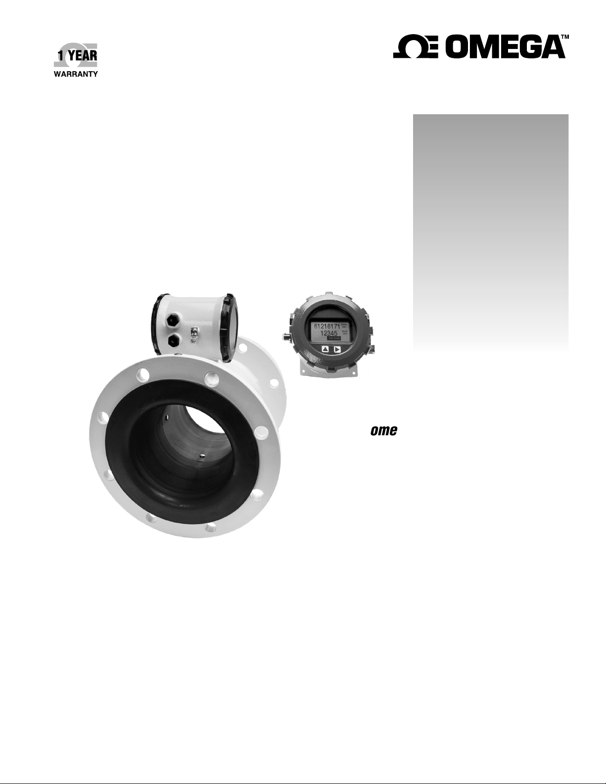
FMG490 SERIES
Municipal/Industrial Magmeter
Page 2

The information contained in this document is believed to be correct, but OMEGA accepts no liability for any errors it contains
the right to alter specifications without notice.
omega.com [email protected]
U.S.A.
Headquarters:
Servicing North America:
FMG490 INSTRUCTIONS
Omega Engineering, Inc.
800 Connecticut Ave, Suite 5N01, Norwalk, CT 06854
Toll-Free: 1-800-826-6342 (USA & Canada only)
Customer Service: 1-800-622-2378 (USA & Canada only)
Engineering Service: 1-800-872-9436 (USA & Canada only)
Tel: (203) 359-1660 Fax: (203) 359-7700
e-mail: [email protected]
For Other Locations Visit omega.com/worldwide
Page 2
, and reserves
Page 3

TABLE OF CONTENTS
FMG490 INSTRUCTIONS
General Information
General Information ...................................................................................................................................................Page 4
Features ...........................................................................................................................................................................Page 4
Specications ................................................................................................................................................................Page 5
Dimensions ....................................................................................................................................................................Page 6
Accuracy ..........................................................................................................................................................................Page 7
Flow Rate ........................................................................................................................................................................Page 7
Installation
Straight Pipe Recommendations ...........................................................................................................................Page 8
Full Pipe Recommendations ....................................................................................................................................Page 9
Positioning the Meter ..................................................................................................................................................Page 10
Installing Gaskets ...........................................................................................................................................................Page 10
Tightening Flange Bolts ..............................................................................................................................................Page 11
Equalization and Grounding (Metal and Plastic Pipe) .....................................................................................Page 11
Connections
General Cable Information .......................................................................................................................................Page 12
Cable Gland Opening and Sealing ........................................................................................................................Page 12
Cable Installation .........................................................................................................................................................Page 13
Wiring Diagrams ..........................................................................................................................................................Page 14
Cable Wiring Table ......................................................................................................................................................Page 15
Conguration
Sourcing Mode Output Application .....................................................................................................................Page 16
Sinking Mode Output Application ........................................................................................................................Page 16
Analog (4-20mA Current Loop) Output Application .....................................................................................Page 16
Cable Shield ...................................................................................................................................................................Page 17
Pulse Output ..................................................................................................................................................................Page 17
Analog (4-20mA) Output ..........................................................................................................................................Page 17
Operation
Changing Flow Meter Settings - Home Screen and General Navigation ..............................................Page 18
Changing Flow Meter Settings - Changing Total Direction/Resetting Totalizer .................................Page 18
Changing Flow Meter Settings - Entering Menu System .............................................................................Page 18
Changing Flow Meter Settings - Making Selections......................................................................................Page 18
Changing Flow Meter Settings - Standard Menu Options ..........................................................................Page 19
Changing Flow Meter Settings - Special Submenu ........................................................................................Page 19
To Change a Passcode ...............................................................................................................................................Page 20
Power Indicators ..........................................................................................................................................................Page 21
Troubleshooting & Error Messages
Problem ...........................................................................................................................................................................Page 22
Probable Cause.............................................................................................................................................................Page 22
Things to Try ..................................................................................................................................................................Page 22
Error Messages .............................................................................................................................................................Page 22
Page 3
Page 4
GENERAL INFORMATION
FMG490 INSTRUCTIONS
The FMG490 Series is a spool-type electromagnetic
owmeter for use in irrigation applications in 3” to 12” pipe.
With no moving parts, these meters provide unobstructed
ow and are resistant to wear from debris found in ground
or surface water. Little maintenance is required because
there are no bearings to wear out or propellers to stop
turning. Minimal straight pipe requirements allow FMG490
meters to be used in piping congurations where there is
little space between the meter and an elbow.
The display for the FMG490 is mounted remotely for ease of
access. The FMG490 is available as either AC or DC powered,
with battery backup. Both rate and total indication show
on the remote mounted display. Bidirectional ow reading
is standard with totals available in forward, reverse, net
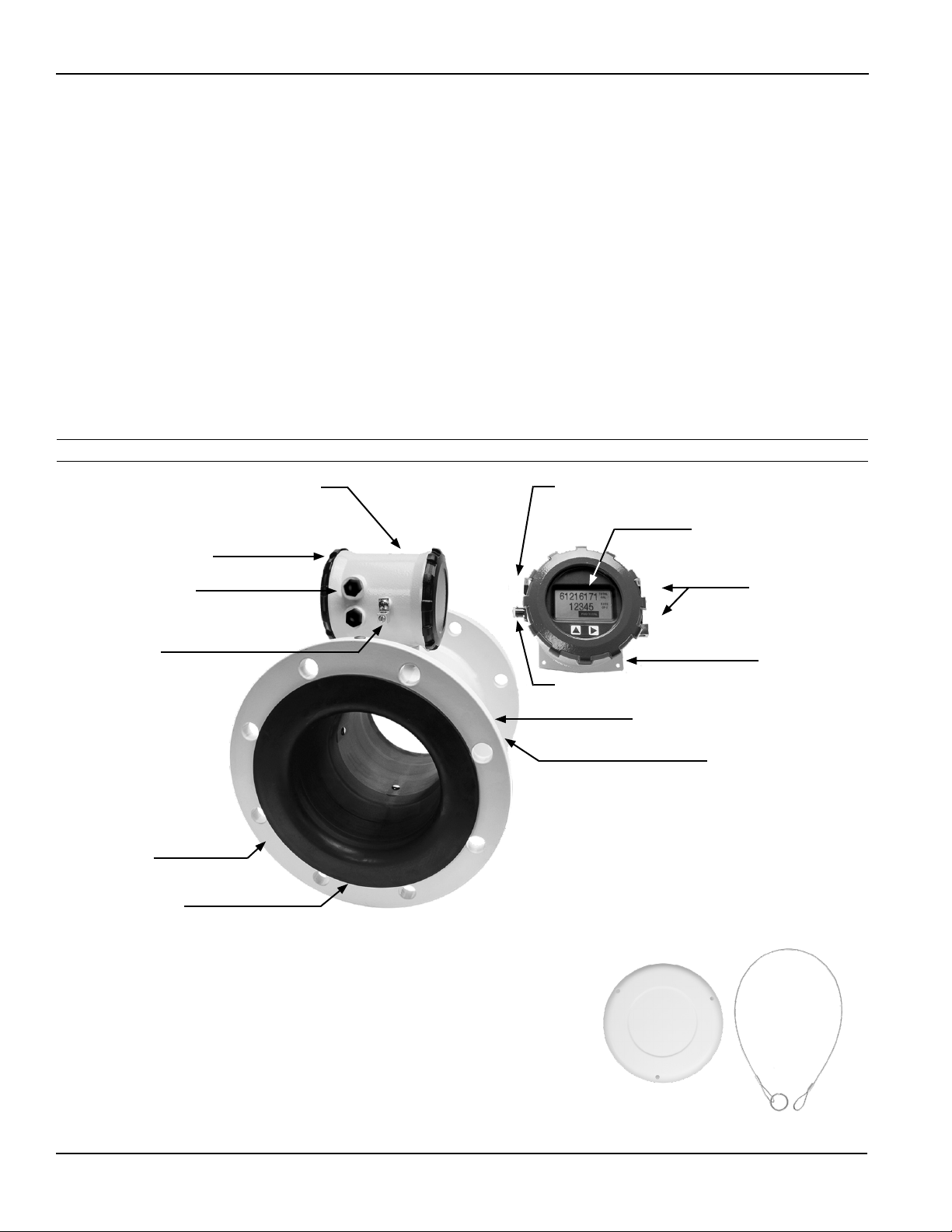
Features
Powder-coated diecast aluminum housing
User access lid (on back)
ow, batch forward ow, and batch reverse ow. Batch
totals can be reset. Built-in data logging is available as an
option for secure ow logging.
Scaled pulse output is standard and one additional output
can also be added, such as 4-20mA.
The FMG490 Series is CE certied and IP68 for burial, or
applications where the meter may be under water for
prolonged periods of time. All meters are provided with
a security seal to protect against unauthorized access.
The seal can be broken by an authorized agent to replace
the battery pack or eld install a power/output cable. The
cable(s) are eld installed.
Remote cable access
Rate and total indicator with
light sensor button controls
Remote cable access
Equalization lug
Flanges, 150 lb.
ANSI pattern
Santoprene/
Polypropylene Liner
Power and Output
cable port access
Mounting ange
Data logger port
Welded steel epoxy-coated ow tube
316SS electrodes (Inside)
No moving parts!
Snap on faceplate
cover and lanyard
Page 4
Page 5
GENERIAL INFORMATION
FMG490 INSTRUCTIONS
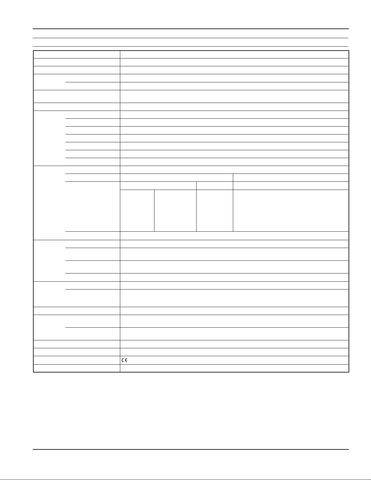
Specications*
Pipe Sizes 3”, 4”, 6”, 8”, 10”, 12”
Flanges 150 lb. ANSI Pattern
Pressure 150 psi (10.3 bar) line pressure
Temperature Operating 10˚ to 140˚ F (-12˚ to 60˚ C)
Storage -40˚ to 158˚ F (-40˚ to 70˚ C)
Accuracy ±0.75% of reading on FMG480 and FMG490 (±1.0% FMG470), ±0.025% of full-scale ow from low ow
Low Flow Cuto 0.5% of maximum ow rate
Material Body
(3”only) Ductile cast iron, powder coated
Body
(4”-12”) Welded steel, epoxy-coated
Liner
(3”only) Noryl
Liner (4”-12”) Santoprene ange/Polypropylene liner body
Electronics Housing Powder-coated diecast aluminum
Electrodes 316 stainless steel
O-ring
(3” only) EPDM
Display Type 128x64 dot-matrix LCD
Digits 5 Digit Rate 8 Digit Total
Units
PleaseNote:
AllFMG470metersare
factorysetforgallonsper
minute(GPM)rateandacre
feettotal.Ifotherunitsare
required,theycanbesetin
theeld.
Bidirectional Forward Total, Reverse Total, Net Total, Batch Forward Total, Batch Reverse Total (Batch totals can be reset)
Power DC Power 9-36 Vdc @ 250 mA max, 30 mA average
Battery Backup
(Not for use as primary power)
Scaled Pulse
Output
AC Power
FMG480only)
Battery
Signal Current sinking pulse, isolated, 36 Vdc at 10 mA max
Pulse Rates User-scalable from 0.1 to 99,999.9 volume units/pulse. Pulse width is one-half of pulse period with
(FMG490and
(FMG470only) One lithium 7.2V ‘D’ size battery pack, replaceable.
Options 4-20mA Current Loop Isolated, passive, 24Vdc, 650 Ω maximum current loop
Cable Power/Output Cable 20ft (6m) standard length polyurethane jacketed cable—for power and outputs (lengths up to 200’
Remote Display Cable
(FMG490)
Conductivity >20 microSiemens/cm
Empty Pipe Detection Hardware/software, conductivity-based
Regulatory
Environmental NEMA 6P, IP68 (10ft (3m) depth, continuously)
* Specicationssubjecttochange.
2
RateTimeUnitisavailableinDayonly.
cuto to maximum ow rate of 10 m/sec
®
Rate Volume Units Rate Time Units Total Volume Units
Gallons
Liters
Barrels(42 gal)
Cubic Feet
Cubic Meters
Million Gallons
Mega Liters
2
Imperial Gallons
Million Imperial
Gallons
2
Second
Minute
Hour
Day
Gallons
Gallons x 10
Gallons x 100
Gallons x 1000
Million Gallons
Liters
Kilo Liters
Mega Liters
Barrels (42 gal)
Cubic Meters
Cubic Meters
x 1000
Cubic Feet
Cubic Feet x 1000
Second Foot Day
Million Cubic Feet
Acre Feet
Acre Inches
Imperial Gallons
Imperial Gallons
x 1000
Million Imperial
Gallons
Fluid Ounces
2
DC powered units: Two lithium 3.6V ‘D’ batteries, replaceable.
AC powered units: One 9V alkaline battery, replaceable.
85-264Vac, 50/60Hz, 0.12A
minimum pulse width of 2.5 ms, 200 pulses/sec max. For battery option meters, pulse width varies with
frequency, 150 pulses/sec max.
available).
20ft (6m) standard length polyurethane jacketed cable—for connection between meter and remote
display (lengths up to 200’ available).
(EN 61326)
Page 5
Page 6
GENERAL INFORMATION
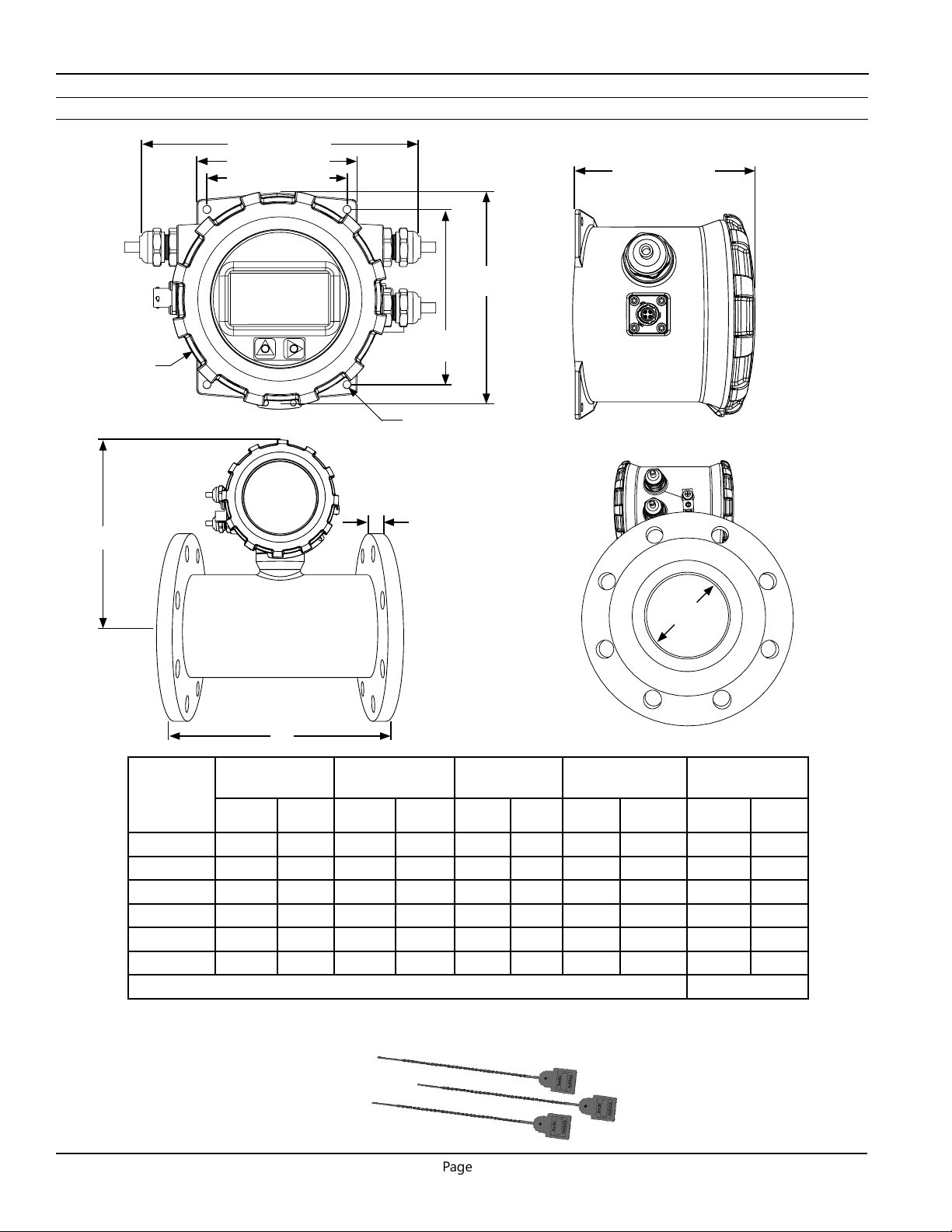
Dimensions
FMG490 INSTRUCTIONS
Ø 5.285”
(134.2mm)
H
6.840” (173.7mm)
4.000” (101.6mm)
3.500” (88.9mm)
Remote Display
4.150” (105.4mm)
5.200”
(132.1mm)
4.375”
(111.1mm)
Ø 0.200”
(5.08mm)
Remote Meter
T
ID
L
FMG490
Meter
Size
L H T ID
inch mm inch mm inch mm inch mm lbs
Shipping
Weight
3”* 12.25 311 7.08 179.8 .68 17.25 2.6 66.04 40 18
4” 10.12 257 8.3 211 .62 15.7 3.12 79 43 19.5
6” 12.09 307 9.1 231 .69 17.5 5.05 128 59 27
8” 14.14 359 10.1 257 .69 17.5 6.44 164 78 35
10” 18.08 459 11.2 284 .69 17.5 8.61 219 135 61
12” 19.68 500 12.2 310 .81 20.6 10.55 268 175 79
Flanges Standard ANSI 150 lb. drilling Cable 1 lb.
*Add8lbs(3.5kg)forremotedisplay.3”Only.
Note: ‘L’ dimension is total from liner face to liner face
Kg
Install security seals during
installation if regulations require.
Page 6
Page 7
GENERAL INFORMATION
1
2
3
4
5
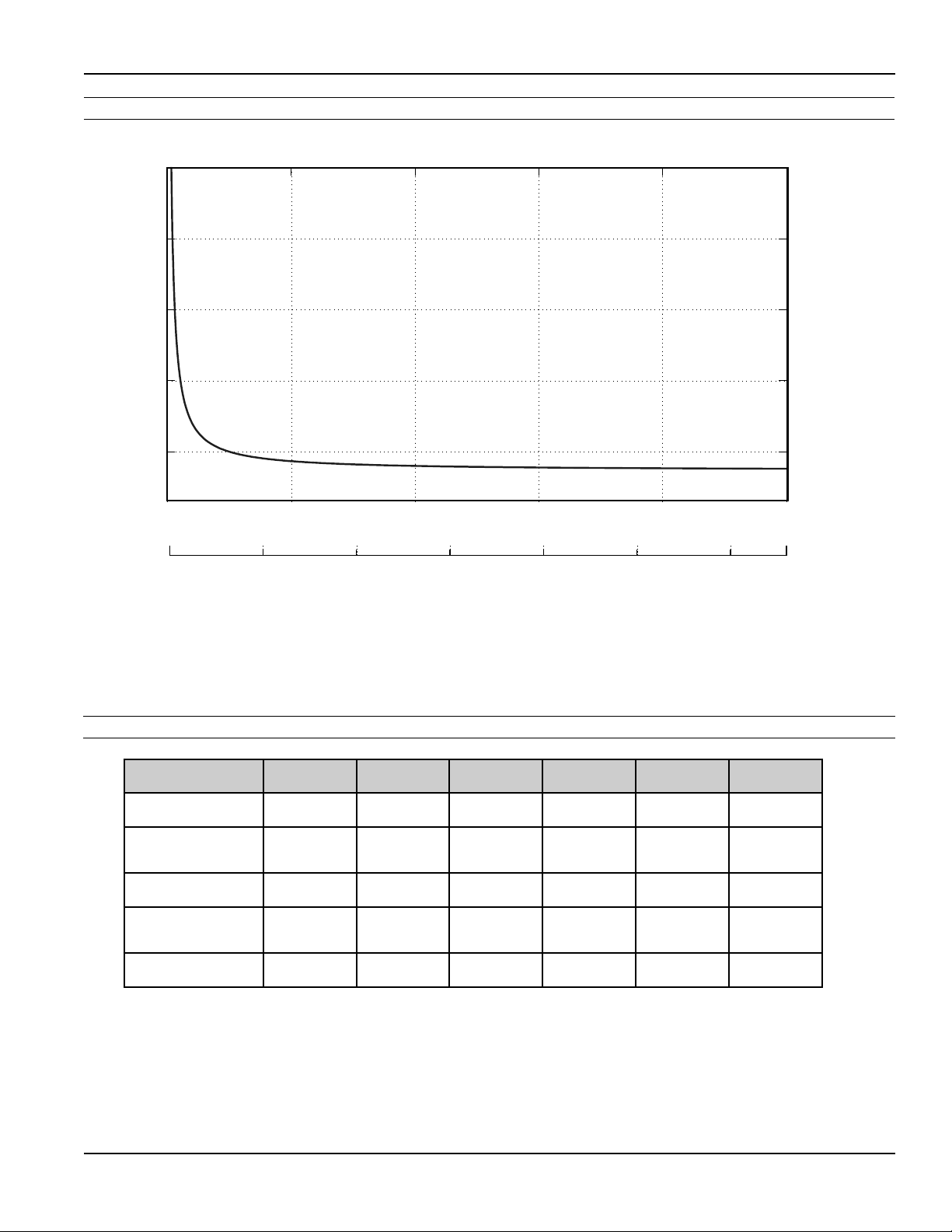
33 0 5 10 15 20 25 30
FMG490 Accuracy
5
4
3
FMG490 INSTRUCTIONS
Accuracy (%)
2
1
33
(m/s)
(ft/s)
0
0
0
5
10 15
420 6 8 10
20
25 30
Flow Velocity
Flow Rate (3” - 12”)
Pipe Size
(Inchesindiameter)
Max Flow Rate
(Gallons/Minute)
Cut-o (min) Flow
Rate
(Gallons/Minute)
Max Flow Rate
(Liters/Second)
Cut-o (min) Flow
Rate
(Liters/Second)
Max Flow Velocity
(Meters/Second)
3” 4” 6” 8” 10” 12”
723 1285 2891 5140 8031 11565
3.62 6.43 14.46 25.70 40.15 57.82
46 81 182 324 507 730
0.23 0.41 0.91 1.62 2.54 3.65
10 10 10 10 10 10
Page 7
Page 8
INSTALLATION
FMG490 INSTRUCTIONS
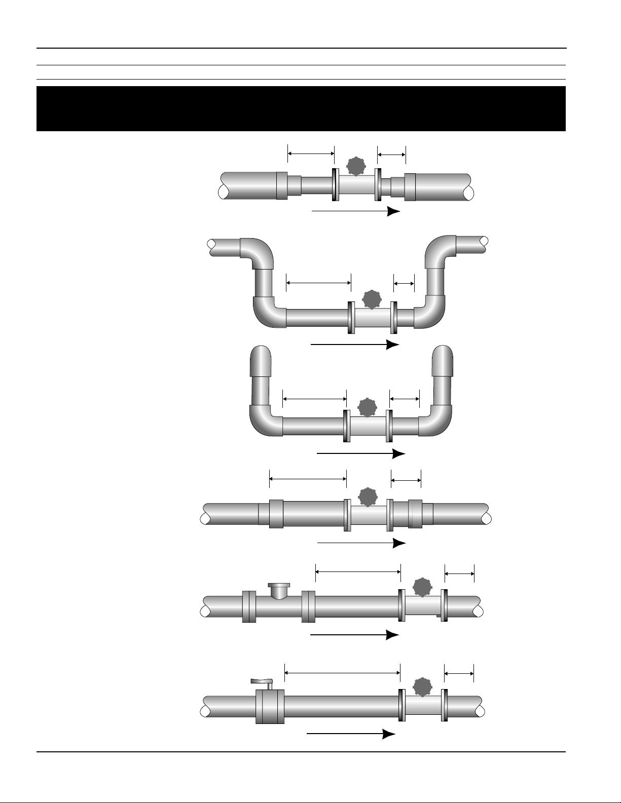
Straight Pipe Recommendations (X=diameter)
NOTE: These congurations are to be used as general guidelines and do not cover every possible installation. A
combination of two or more obstructions will require additional straight pipe. If there is any concern about the
length of pipe required for a specic application, please contact your local dealer.
Reduced Pipe
Two Elbows In Plane
Two Elbows, Out Of Plane
2X
2X
2X
1X
1X
1X
Expanded Pipe
Swirling Flow:
Propeller Meter
Swirling Flow:
Partially Open
Buttery Valve
5X
Page 8
5X
5X
1X
12345
1X
1X
Page 9
INSTALLATION
12345
12345
12345
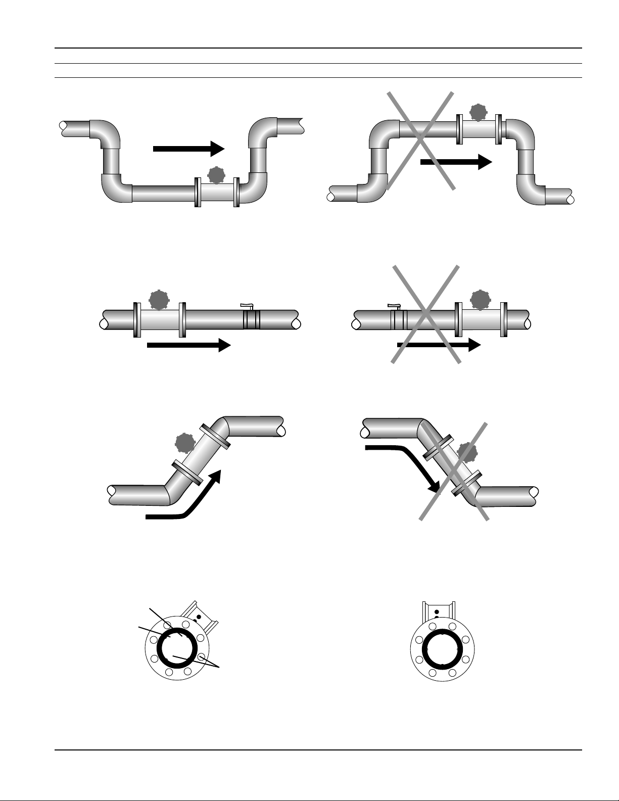
Full Pipe Recommendations
FMG490 INSTRUCTIONS
Recommended:
Keep pipe full at meter for accuracy
12345
Recommended:
Keeps pipe full at meter for accuracy
Not Ideal:
Allows air pockets to form at meter
Not Ideal:
Post-valve cavitation can create air pocket
12345
Recommended:
Allows air to bleed o
Intermittent air
bubbles
miss electrode
Electrode
moved from
top by rotating
meter
Recommended:
Improved accuracy results from
unimpeded electrodes
Electrodes free
from sediment
build-up
Page 9
Not Ideal:
Air can be trapped
Not Ideal:
Air bubbles and sediment on the
electrodes can aect accuracy
Page 10
INSTALLATION
FMG490 INSTRUCTIONS
Positioning the Meter
CAUTION: These ow sensors are not
recommended where installation may
expose the ow sensor to boiler pressure
and temperature. Maximum recommended
operating temperature is 130˚ F.
These meters can be installed horizontally, vertically (with
upward ow), and in any radial position. Using a check
valve on the upstream side of the meter, and/or an air
vent (vacuum relief valve) in the same, unobstructed run
of pipe as the meter, is required in any installation where
the meter may be exposed to suction when the system
is not in normal operation. Suction can cause damage
to the liner. Liner damage caused by suction, without
the use of a check valve and/or air vent, may void the
warranty.
Straight Pipe Recommendations. The FMG490 requires
straight pipe before and after the meter for best accuracy.
However, the ability of electromagnetic meters to average
the ow across the entire pipe allows for shorter straight
pipe recommendations than most mechanical meters (see
page 8).
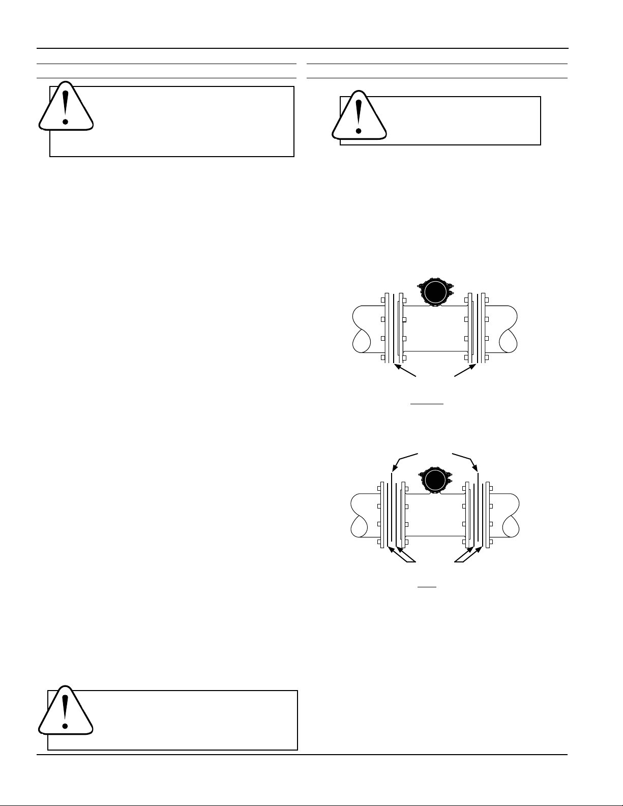
Installing Gaskets
GASKETS
Gaskets are required at all
junctions.
1. Be sure all mating surfaces are smooth and free of
debris.
2. Install provided gaskets, or equivalent, on each
end of meter as shown in diagrams below. If using
grounding rings, install one gasket on each side of
the grounding ring.
3. Failure to install gaskets will void warranty.
Full Pipe Recommendations. To prevent false readings,
this meter is designed to indicate ‘EMPTY PIPE’ if one or
more electrodes is exposed. For highest accuracy, install
the meter so that the pipe will be full when there is
ow. If air bubbles may be present in the pipe or sludge
accumulation is an issue, rotate the meter by one ange
hole to position the control housing at a 45˚ angle (see
diagrams on page 9).
Fittings. The meters have ANSI 150 lb. drilled anges and
will mate with any other ANSI 150 lb. anges. Seetable
onpage11forangebolttighteningtorquespecications.
Calibration. The FMG490 meters are factory-calibrated
and will not require any form of eld calibration.
Chemical Injection. When an FMG490 meter is used in a
chemical injection application, the chemical injection
point must be placed downstream of the magmeter OR
far enough upstream for complete mixing to occur
before the uid reaches the meter. When unmixed
chemical alternates with water passing through the meter,
the rapid changes in conductivity may cause sudden spikes
and drops in the meter’s reading, resulting in inaccurate
measurement. The magmeter will restabilize, however,
with a steady ow of uid of uniform conductivity.
Gaskets
Installationwithoutgroundingrings
Grounding
Rings
Gaskets
Installationwithgroundingrings
CAUTION: In chemical injection applications,
install chemical injection point downstream
of magmeter, or far enough upstream to
allow complete mixing of uids.
Page 10
Page 11
INSTALLATION
FMG490 INSTRUCTIONS
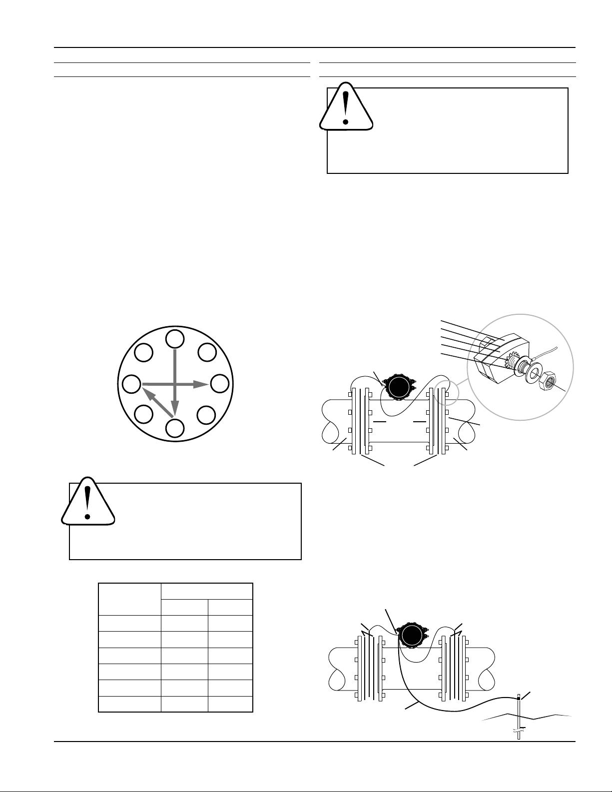
Tightening Flange Bolts
NOTE: Mating pipe anges must be ANSI 150# full face (FF)
and/or raised face (RT).
1. Tighten ange bolts in an alternating pattern.
• Tighten left ange bolt-1 to 20% recommended
torque.
• Tighten right ange bolt-1 to 20% of
recommended torque.
• Repeat steps a and b for each bolt in an
alternating order, such as shown at right,
tightening to 40%, then 60%, then 80%, and
then 100%.
2. Test for leaks.
3. If needed, tighten further in 10% increments
until leaking stops. DO NOT over-tighten. Over-
tightening can cause serious damage to the ow
meter.
4. Recheck after 24 hours, adjusting if needed.
1
5
8
Equalization and Grounding
WARNING: ELECTRICAL SHOCK HAZARD
When the FMG490 is installed in a plastic
piping system, or when externally powered,
the piping system must be grounded to
meet national and local electrical safety codes. Failure
to do so can result in electrocution.
Metal Pipe Installations. To equalize the electrical
potential of the uid, the FMG490 meter, and the
surrounding pipe, secure the ange plates (factory-installed
on the equalization wire) to both pipe anges at one of the
bolt holes, as shown below. Be sure the lock washer ts
between the pipe ange and the ange plate. For the best
electrical bonding, remove rust and paint to expose clean,
bare metal where the equalization ange plate lock washer
contacts the pipe ange. Connection must be inspected
periodically for corrosion to maintain the necessary low
resistance connection.
Meter Flange
Gasket
Pipe Flange
Lockwasher
Flange Plate
Equalization Lug
3
7
4
6
2
SuggestedTighteningSequence
Caution: Improper tightening sequence
can cause serious damage to the ow
meter.
• Do not tighten one side at a time.
• Do not tighten each bolt completely
at one time.
SUGGESTED FLANGE BOLT TORQUE
Santoprene Liner
Pipe Size ft-lb Nm
3” 25 34
4” 20 27
6” 42 57
8” 65 88
10” 73 99
12” 97 132
Meter
Flange
Gaskets
Pipe
Flange
Metal PipeMetal Pipe
Plastic Pipe and Electronically Noisy Installations. When
the FMG490 is installed in plastic pipe or in an electrically noisy
system (near a VFD etc.), grounding rings are recommended.
As shown in the diagram below, the equalization wires should
be solidly connected to the grounding ring tabs instead of the
ange bolts as in metal piping installations. Where lightning
is a threat, or in severe electrical environments, an optional
connection to a nearby equipment ground or ground rod may
be advisable.
Grounding Ring Part Numbers:
4” = 100876 10” = 100879
6” = 100877 12” = 103288
8” = 100878
Grounding Ring
Gaskets
Plastic
Pipe
Ground Clamp
(Exothermicallyweldwhen
corrosionisaconcern)
Earth
8’ Ground Rod
Grounding Ring
Gaskets
Plastic
Pipe
Equalization Lug
#6, #8, or #12 AWG Stranded
Copper Ground Wire < 5’
Page 11
Page 12
CONNECTIONS
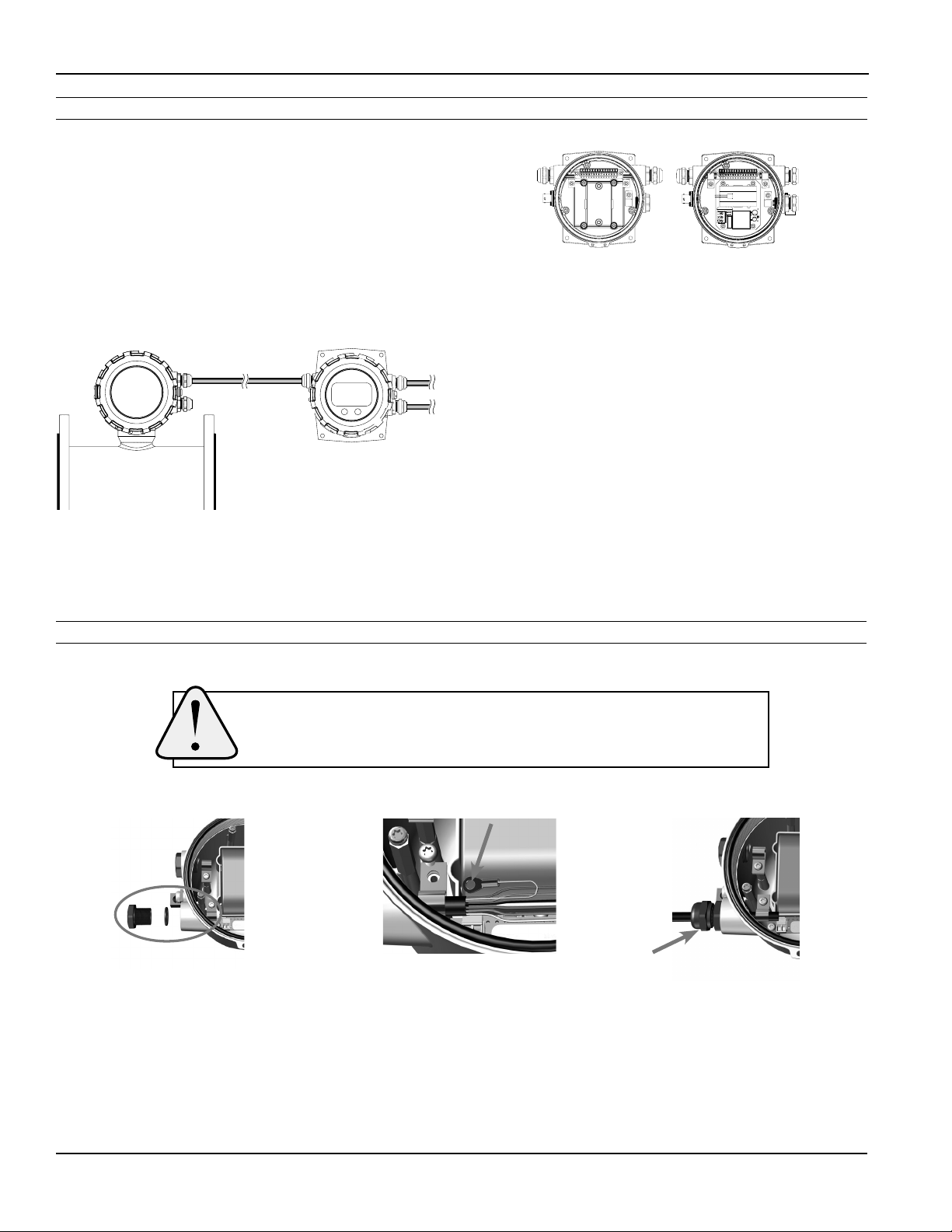
General Cable Information
FMG490 INSTRUCTIONS
For the FMG490, a cable needs to be installed from the
terminal block on the remote display interface board to the
15 pin connector inside the remote display. This cable is
referred to as the remote meter cable. There are four wires
in the cable: +REM PWR, - REM PWR, B, and A. There
are an additional 2 cable ports that can be used for power
(DC or AC) and any outputs that are installed on the meter
such as scaled pulse, 4-20mA, HART, and Modbus® . (See
Sample Control Cable Wiring Diagrams and Control Cable
Wiring Table.)
Remote
Meter
Remote Meter
Cable
Remote
Display
Power/
Output
Cable 1
Power/
Output
Cable 2
The display is available in either DC or AC versions.
DCversion ACVersion
If the meter is congured with AC power, one of the
additional Power/Output cable ports must be reserved
for AC power only. We do not recommend combining AC
power signals with any of the meter outputs in a single
cable. If the meter is congured for DC power, you may
have one or two cables, depending on conguration. (See
Cable Wiring Diagrams.)
Cable Gland Opening and Sealing
WARNING: Improper sealing of glands or cables will invalidate any warranty.
If plugs or cable glands are removed, reinstall using Teon pipe sealant, or
tape, to ensure maximum moisture protection.
Removeplug&o-ring.Insert
cablegland/strainrelief.Feed
cablethroughcablegland.
Clampcablewithstrainrelief
clips.Attachdrainwirelugto
bracketpost.
CRITICAL!
Torquecableglandsealing
nutto22in-lbs.
Page 12
Page 13
CONNECTIONS
Cable Installation
FMG490 INSTRUCTIONS
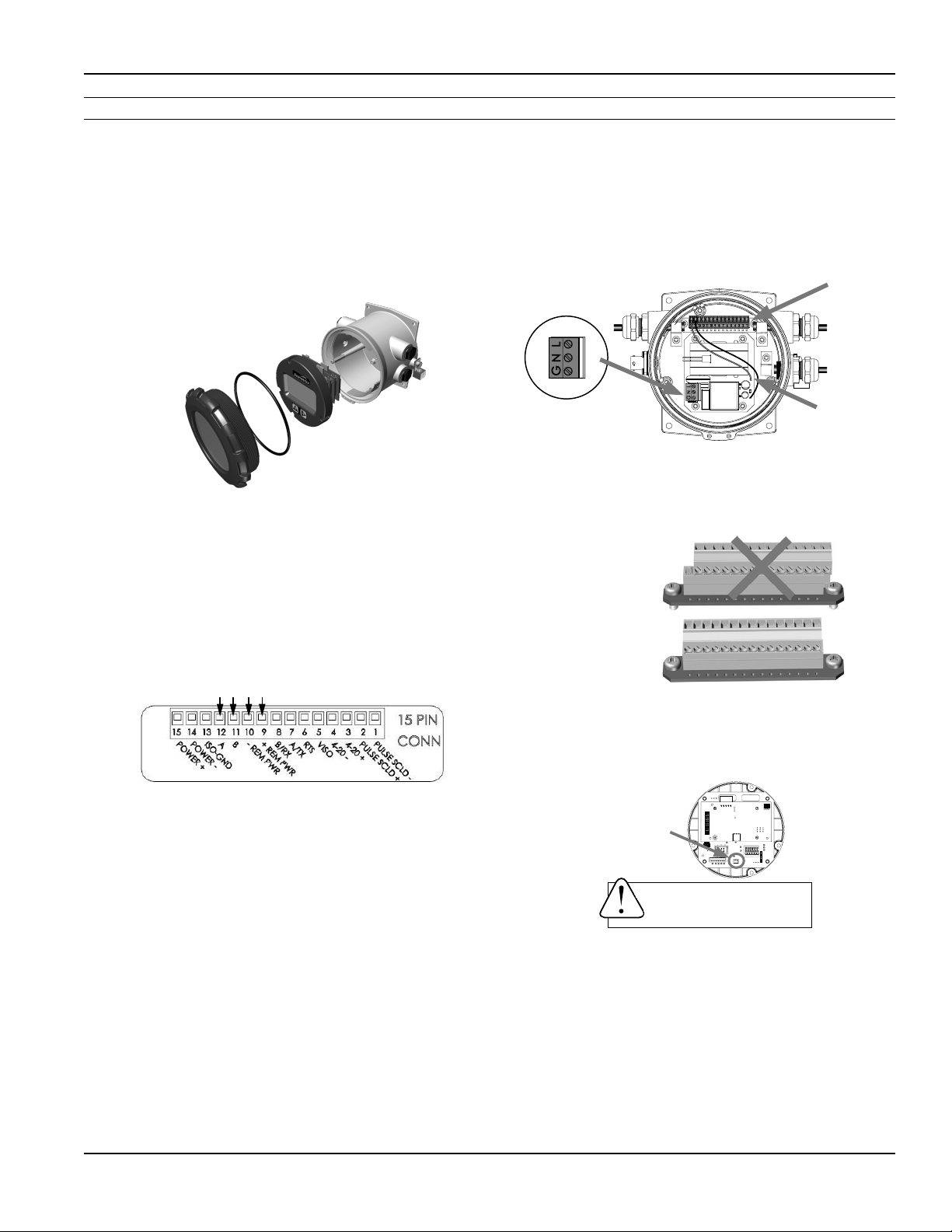
Remote Display Wiring
1. On the remote display, unscrew the display lid and
remove it.
2. Remove the 3 screws holding the display assembly
and remove it from the meter exposing the internal
15 pin connector. Be sure to NOT undo any
connections to the display assembly as you remove
it.
3. Remove the 15 pin screw connector from the bag.
4. Remove the plug and o-ring from the cable port(s)
where you want to insert the cable(s).
5. Install cable gland(s) using Teon pipe sealant, or tape,
and insert cable end(s).
6. Strip cable jacket and conductors and install the
wires into the screw connector in their respective
locations (+Rem Pwr (red), - Rem Pwr (black), B
(orange), and A (blue)).
10. Remove the plug and o-ring from the AC cable
port.
11. Install cable gland and insert cable end.
12. Strip cable jacket and conductors and install 3
conductor power cable and wire to Line (L), Neutral
(N) and ground (G) positions on power supply
terminal block.
15pin
connector
Power
supplyterminal
Internal
ACwires
block(ACversions)
13. Plug the 15 pin screw connector into its socket.
Be sure all pins align properly and that the
connector has not slipped to one side.
Improper
alignment
Proper
alignment
7. At this point, install any other options using the
Power/Output cable(s) through the Power /Output
cable port(s), and securely screw them into the
screw connector in their respective locations. (See
Cable Wiring Table for details.)
8. If using AC power version continue here. If not, then
skip to step 13. If AC then take the red and black
wires coming out of the AC supply board and install
in POWER+ and POWER- (red wire to pin 15, black
wire to pin 14).
9. When the AC power supply board is installed,
85-264 VAC power is supplied via a user-supplied
3 conductor power cord having local regulatory
agency approval. If installed outdoors or less than
33ft. (10m) from a utility power service entrance, AC
power should be supplied via a properly-grounded
surge suppression device.
Page 13
14. Plug the backup battery cable into the back of
the display assembly. (Standard backup batteries
are two 3.6V “D” lithium cells. For the AC option, the
backup battery is one 9V alkaline cell.)
Backup
battery
connection
WARNING: BACKUP BATTERIES
ARE NOT INTENDED AS A PRIMARY
POWER SOURCE OF A MAINS (DC or
AC) CONFIGURED METER.
15. Secure the cables inside the internal strain relief
clips and tighten the cable gland sealing nuts
securely (torque strain relief/sealing gland dome
nut to 22 in-lbs). A loose nut could cause moisture
ingress and compromise the meter head’s IP68
rating, voiding the warranty.
16. Remount the display assembly, being careful to not
pinch any wires, and install the display assembly
screws.
17. Reinstall the display lid, being sure to avoid crossthreading the lid.
Page 14
CONNECTIONS
Cable Installation
FMG490 INSTRUCTIONS
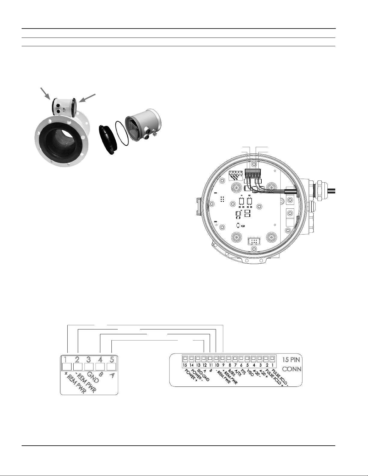
Remote Meter Wiring
1. On the remote meter, unscrew the user access lid
and remove it.
Useraccesslid Frontpanel—
donotopen
2. Remove the 5 pin screw connector from its socket.
3. Remove the plug and o-ring from the cable port.
4. Install cable gland and insert cable end.
5. Strip cable jacket and conductors and install
the wires into the 5 pin screw connector in their
respective locations (+Rem Pwr (red), - Rem Pwr
(black), B (orange), and A (blue)).
6. Secure the remote sensor cable inside the internal
strain relief clip and tighten the cable gland sealing
nut securely (torque strain relief/sealing gland
dome nut to 22 in-lbs.). A lose nut could cause
moisture ingress and compromise the meter head’s
IP68 rating; voiding the warranty. Plug the 5 pin
screw connector into its socket.
7. Reinstall the user access lid. Be sure to avoid crossthreading the lid and to not pinch any wires with
the lid.
Black (R) -Remote Pwr: pn2
Red (R) +Remote Pwr: pn1
Orange (R) Remote B: pn4
Blue (R) Remote A: pn5
R
Remote Meter
RED
BLACK
ORANGE
BLUE
Remotemeter 15pinconnectorinremotedisplay
Page 14
Page 15
CONNECTIONS
FMG490 INSTRUCTIONS
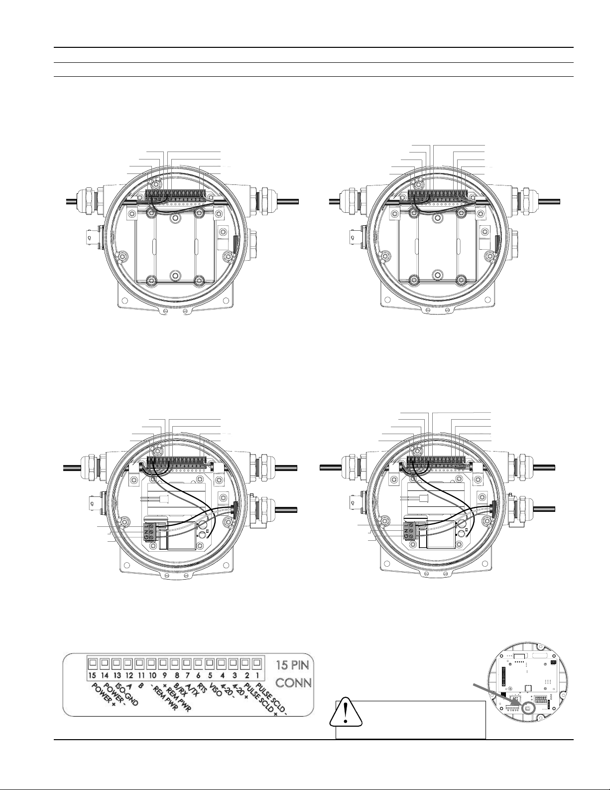
Wiring Diagrams (Remote Display)
Remove the 3 screws holding the display assembly and remove it from the meter. Remove the 15 pin screw connector
from its bag. Install the wires through the cable glands into the 15 pin screw connector in their respective locations. Plug
the 15 pin screw connector into its socket. (C1=power/outputcable1,C2=power/outputcable2,R=remotecable)
Orange (R) Remote B: pn11
Blue (R) Remote A: pn12
Black (C1) DC-: pn14
Red (C1) DC+: pn15
R
DC Power with Pulse (D5N/D6N)
Black (R) -Remote Pwr: pn10
Red (R) +Remote Pwr: pn9
Green (C1) Pulse+: pn2
White (C1) Pulse-: pn1
C1
Black (R) -Remote Pwr: pn10
Orange (R) Remote B: pn11
Blue (R) Remote A: pn12
Black (C1) DC-: pn14
Red (C1) DC+: pn15
R
DC Power with Pulse and 4-20mA (D5I/D6I)
Red (R) +Remote Pwr: pn9
Blue (C1) 4-20mA-: pn4
Orange (C1) 4-20mA+: pn3
Green (C1) Pulse+: pn2
White (C1) Pulse-: pn1
C1
Remove the 3 screws holding the display assembly and remove it from the meter. Remove the 15 pin screw connector
from its bag. Install the wires through the cable glands into the 15 pin screw connector in their respective locations. Plug
the 15 pin screw connector into its socket. (C1=power/outputcable,R=remotecable,AC=ACpowercable)
Orange (R) Remote B: pn11
Blue (R) Remote A: pn12
Black (Internal): pn14
Red (Internal): pn15
Black (R) -Remote Pwr: pn10
Red (R) +Remote Pwr: pn9
Green (C1) Pulse+: pn2
White (C1) Pulse-: pn1
Black (R) -Remote Pwr: pn10
Orange (R) Remote B: pn11
Blue (R) Remote A: pn12
Black (Internal): pn14
Red (Internal): pn15
Red (R) +Remote Pwr: pn9
Blue (C1) 4-20mA: pn4
Orange (C1) 4-20mA+: pn3
Green (C1) Pulse+: pn2
White (C1) Pulse-: pn1
R
Black (Line)
White (Neutral)
Green (Ground)
AC Power with Pulse (A5N/A6N)
C1
AC
Page 15
R
Black (Line)
White (Neutral)
Green (Ground)
AC Power with Pulse and 4-20mA (A5I/A6I)
Plug the backup battery
cable into the back of the
display assembly.
WARNING: BACKUP BATTERIES
ARE NOT INTENDED AS A PRIMARY
POWER SOURCE OF A MAINS
(DC or AC) CONFIGURED METER.
C1
AC
Page 16
CONNECTIONS
FMG490 INSTRUCTIONS
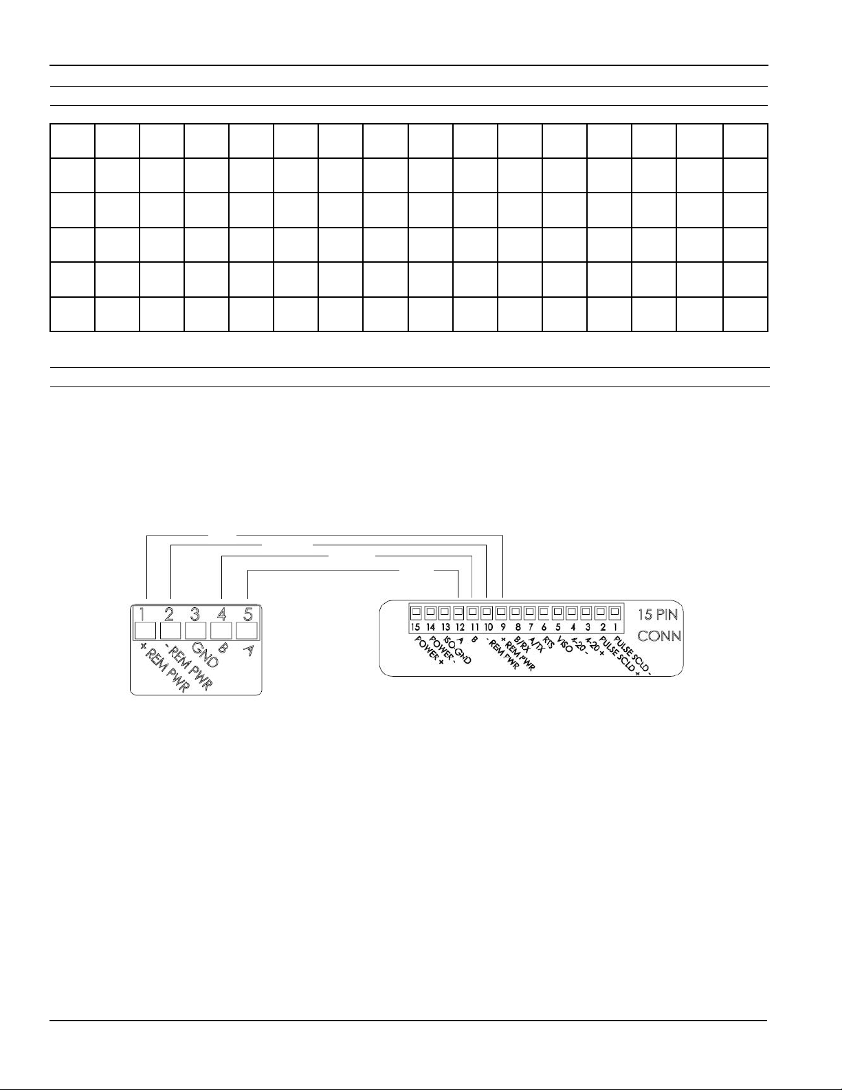
Cable Wiring Table
PIN 15 14 13 12 11 10 9 8 7 6 5 4 3 2 1
O ID PWR+ PWR-
D5N/
D6N
D5L/
D6L
A5N/
A6N
A5L/
A6L
REDC1BLACK
REDC1BLACK
RED
INT
RED
INT
C1
C1
BLACK
INT
BLACK
INT
ISO-
GND
A B
BLUERORNGRBLACKRRED
BLUERORNGRBLACKRRED
BLUERORNGRBLACKRRED
BLUERORNGRBLACKRRED
-REM
PWR
+REM
PWR
R
R
R
R
B/RX A/TX RTS VISO 4-20 - 4-20 +
BLUEC1ORNGC1GREENC1WHITE
BLUEC1ORNGC1GREENC1WHITE
PULSE
SCLD+
GREENC1WHITE
GREENC1WHITE
PULSE
SCLD-
C1
C1
C1
C1
(C1 = power/output cable 1 C2 = power/output cable 2 R = remote cable INT = Internal AC power wires)
Option IDs
O ID POWER SOURCE / OUTPUT(S)
D5N/D6N = DC POWER / PULSE SCALED
D5I
/D6I = DC POWER / PULSE SCALED AND 4-20mA
RED
BLACK
ORANGE
O ID POWER SOURCE / OUTPUT(S)
A5N/A5N = AC POWER / PULSE SCALED
A5I/A6I = A
BLUE
C POWER / PULSE SCALED AND 4-20mA
Page 16
Page 17
CONFIGURATION
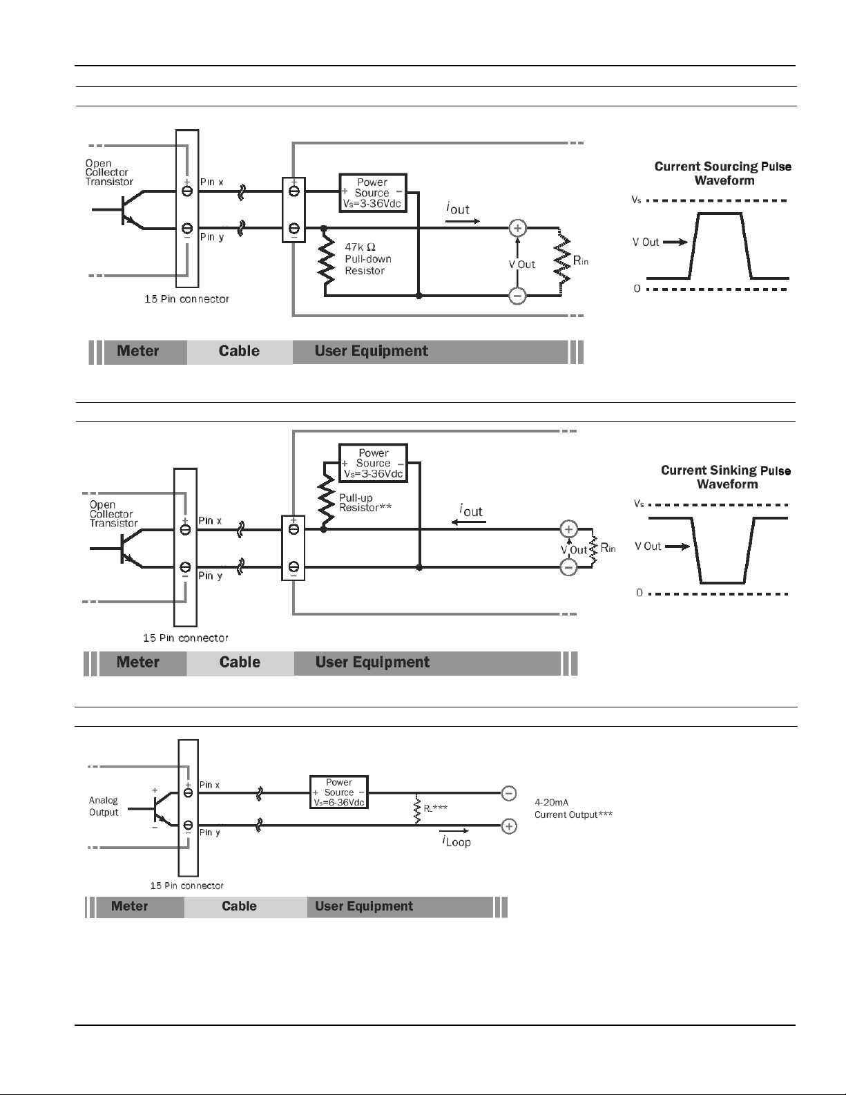
Pulse or Digital Output Application - Sourcing Mode (Recommended for Rin < 30kΩ)
Pulse or Digital Output Application - Sinking Mode (Recommended for Rin > 30kΩ)
FMG490 INSTRUCTIONS
Analog (4-20mA Current Loop) Output Application
**Minimumresistorvalueis(100xVs)ohms.Higherresistancesmaybeuseddependingonfrequencyandcablelength.
Longercablesandhighfrequenciesrequirelowerresistance.
***ResistorRLconverts4-20mAcurrenttovoltageforvoltageinputonlydevices.
Page 17
Page 18

CONFIGURATION
FMG490 INSTRUCTIONS
Cable Shield. In general, the cable shield and its bare drain
wire should be left unconnected at the user equipment end of
the cable to minimize “ground loop” problems.
Pulse Output Conguration. A pulse output is standard
on all models. Since this is an isolated output, the external
equipment must include a DC power source to regenerate the
pulse from the open-collector output (transistor equivalent
of a contact closure). A pull-up or pull-down resistor may
be needed if not included in the user equipment as shown
in the diagrams. Both the power source and resistor may be
supplied internally in some types of control and monitoring
devices. If not, as for most PLC discrete input modules, they
must be added externally at the module input terminals. The
pulse output rate in volume units/pulse can be set by the user
via the SETP tab on the meter’s setup menus.
Because the pulse output of an FMG490 meter is set by the
user, care must be taken to assure the output pulses do
not exceed the maximum frequency of the meter while also
ensuring a reasonable resolution.
K-factor: Remember that SETP is expressed in units totaled
per output pulse (G/P if using gallons) while K-factors are
expressed in pulses per gallon (P/G.) To determine K-factor
from SETP, divide 1 by SETP (if SETP is expressed in gallons.)
Conversely, 1 divided by the K-factor equals SETP
FMG490 meters that were initially congured as battery
powered units have a maximum output frequency of 150 Hz.
Those that were initially congured as powered units have a
maximum output frequency of 200 Hz.
Because all pulse outputs (SETP) are congured in (rate) units
totaled per pulse, all sizes of meters can be congured with
the same SETP values
For example, if your rate is chosen as gallons per minute
(GPM) the table below applies. If your rate is dierent, simply
use your rate label in place of (GPM.) The numerical values will
remain the same.
SETP
0.1 6 1200 900
0.2 12 2400 1800
0.3 18 3600 2700
0.4 24 4800 3600
0.5 30 6000 4500
0.6 36 7200 5400
0.7 42 8400 6300
0.8 48 9600 7200
0.9 54 10800 8100
1.0 60 12000 9000
Flow Rate at 1
Hz (GPM)
Flow Rate at
200 Hz (GPM)
PoweredMeters
Flow Rate at
150 Hz (GPM)
BatteryPowered
Meters
Lowerfrequencyoutputpulses(1pulseforsomeparticular
numberofgallons)canalsobeset.
Any output frequency can be determined by:
Rate (units/minute) ÷ SETP (units/pulse) = pulse/minute
Hz = pulse/minute ÷ 60 seconds / minutes
Analog Output (4-20mA) Conguration. (Not available
on battery only units.) Since the meter’s analog output
is isolated and passive, loop power must be supplied
externally as shown previously. (In addition, an external
resistor RL will be needed to convert the loop current to
voltage for voltage-only input devices.) The meter’s loop
transmitter minimum voltage drop is 6Vdc (8Vdc with
HART) which, with wiring resistance and loop power supply
voltage, will determine the maximum resistance for RL. The
ow rates corresponding to 4 and 20mA can be set by the
user via the SET 4 and SET20 tabs on the meter’s setup
menus.
Pulse Units. The units of measure of SETP are independently
selectable and are not tied to rate or total. Upon change of the
SETP unit, the pulse output may take up to 10 seconds, or the
duration of one pulse (whichever is longer) to take eect.
If Pulse Output is Inconsistent. The PDAMP lter may need
to be increased.
Pulse Width Timing. The unit and value of SETP must be
chosen to keep the duration between meter pulse outputs to
less than 500 seconds.
Page 18
Page 19
OPERATION
1.2345678
TAP
TAP
1.2345678
100
TOTAL
CU FT
X1000
RATE
GPM
FORWARD TOTAL
1.2345678
100
TOTAL
CU FT
X1000
RATE
GPM
T UNIT R UNIT S ET PDAMP
SET 4SET 20 S ET F EXIT
TOTAL = GALLONS
PRESS + TO SET TOTAL
UNITS FOR DISPLAY
FORWARD TOTAL
TAP
TAP
TAP
TAP
+
HOLD TAP
+
HOLD TAP
+
HOLD
TAP
Changing Flow Meter Settings
FMG490 INSTRUCTIONS
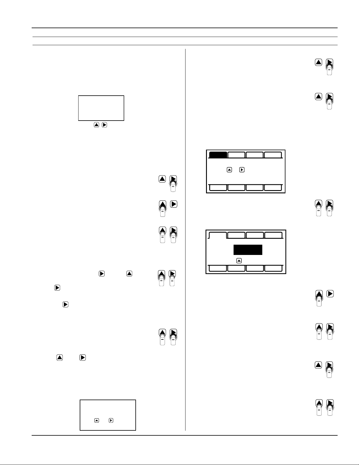
Home Screen and General Navigation
The HOME Screen displays ow volume, direction of the
ow total and ow RATE along with status conditions such
as Empty Pipe. Two buttons below the LCD display are used
to access menu screens for viewing and changing meter
setup parameters.
These two buttons are light sensors which can detect
when a nger is covering them and activate upon
release. Only three button touch actions are needed to
control navigation through the menus, settings changes
and back to the home screen.
HORIZONTAL SCROLLING:
Tap right button to scroll horizontally through
menu tabs or move horizontally within a tab
dialog when applicable.
SELECT:
Tap left button to change a highlighted item
within a tab dialog.
ENTER/EXIT:
Hold left button while tapping right button
once to enter or exit a tab dialog or to navigate
between the HOME and other menu screens.
Changing Total Direction/Resetting Batch
Totalizers
On the Main screen, hold and tap 5 times
to scroll through the total direction options.
Release to select a total direction.
Once BATCH FORWARD or BATCH REVERSE is
selcted, tap four times to reset batch totalizer.
Entering Menu System
To enter the Menu System perform the hold
and tap sequence. The Passcode entry screen
will display. The default passcode is 000000. If
a dierent passcode has previously been set,
use the and to enter that passcode.
In either case, hold and tap again to move
into the menu system. (Ifyouenter thewrong
passcode,hold andtap again toreturn tothe
previousscreen.Seepage21forinformationon
howtochangeapasscode.)
TOTAL
CU FT
X1000
RATE
100
FORWARD TOTAL
GPM
ENTER PASSCODE
000000
PRESS AND TO CHANGE
Making Selections
Once in the Menu System, move from tab to
tab by tapping the right button. (See the next
page for details on the various available tabs.)
Select the parameter. In the screen for
the highlighted tab you will see the current
parameter value for that tab. Tapping the right
button, move to the tab for the parameter you
want to change.
In this example, the rst line indicates that the
current unit for the TOTAL is GALLONS. The
next two lines tell you what to do next.
T UNIT R UNIT SET PDAMP
TOTAL = GALLONS
PRESS + TO SET TOTAL
UNITS FOR DISPLAY
SET 4SET 20 S ET F EXIT
If you would like to change the TOTAL units,
just perform the hold and tap sequence to
bring up a screen to change the setting.
T UNIT R UNIT S ET PDAMP
+
HOLD TAP
TOTAL:
PRESS TO CHANGE
SET 4SET 20 S ET F EXIT
GALLONS
Select a new setting. Select the new setting
by scrolling through a list of selections as in
the screen illustration below by tapping the
left button to nd a dierent TOTAL unit.
Accept changes. To accept any changes
you have made, perform the hold and tap
sequence.
+
HOLD TAP
When nished making changes. When you
are nished making changes, move to the EXIT
tab using the right button.
To return to the HOME screen, perform the
hold and tap sequence.
+
HOLD TAP
Page 19
Page 20
OPERATION
FMG490 INSTRUCTIONS
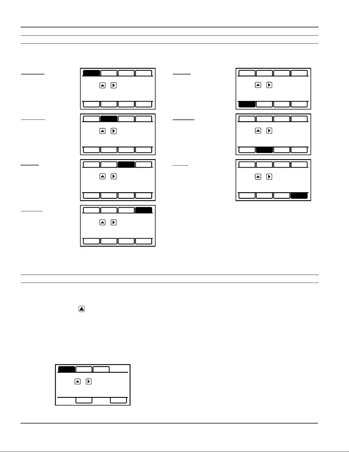
Standard Menu Options
Note: Available options will depend on specic meter conguration. Not all options are available on all meters.
Options not ordered with your meter will not appear on the meter menu.
T UNIT
View or change TOTAL
volume units
R UNIT
View or change ow
RATE units
SET P
View or change pulse
output scaling
DAMP
View or change # of
samples for rolling
average.
T UNIT R UNIT SET P DAMP
TOTAL = GALLONS
PRESS + TO SET TOTAL
UNITS FOR DISPLAY
SET 4 SET 20 SET F EXIT
T UNIT R UNIT SET P DAMP
FLOW RATE = GALLONS/MIN
PRESS + TO SET RATE
UNITS FOR DISPLAY
SET 4 SET 20 SET F EXIT
T UNIT R UNIT SET P DAMP
00001.0 GALLONS
PRESS + TO SET
GALLONS TOTALIZED PER
PULSE SENT OUT PULSE1
SET 4 SET 20 SET F EXIT
T UNIT R UNIT SET P DAMP
DAMPING = 1
PRESS + TO SET
DAMPING VALUE
SET 4
View or change ow
rate corresponding to
4mA.
SET 20
View or change ow
rate corresponding to
20mA.
EXIT
Return to HOME
SCREEN or enter
SUBMENU
T UNIT R UNIT SET P DAMP
00040.0 GALLONS/MIN
PRESS + TO SET FLOW
RATE AT WHICH 4mA
(MIN) OUTPUT IS DESIRED
SET 4 SET 20 SET F EXIT
T UNIT R UNIT SET P DAMP
00200.0 GALLONS/MIN
PRESS + TO SET FLOW
RATE AT WHICH 20mA
(MAX) OUTPUT IS DESIRED
SET 4 SET 20 SET F EXIT
T UNIT R UNIT SET P DAMP
PRESS + EXIT MENU
AND RETURN TO FLOW
DISPLAY
SET 4 SET 20 SET F EXIT
SET 4 SET 20 SET F EXIT
Special SUBMENU for Further Options
The EXIT tab in the MAIN MENU has a second function. If,
instead of using the hold and tap sequence to return to the
HOME screen, you tap ve times, you will be redirected
to a SUBMENU screen from which you can access several
more options.
Navigation in this SUBMENU is the same as for the MAIN
MENU. Whenever you wish, go to the EXIT tab in the
SUBMENU and perform the hold and tap sequence to
return to the MAIN MENU.
INFO COMM MBID FL DIR
PRESS + TO VIEW INFO
ABOUT METER
SAMP
HPOLL FOUT EXIT
INFO: Meter model number, serial number, and rmware
version.
COMM: Modbus® baud rate and parity. (Not available on
battery only units.)
MBID: Modbus® address (Not available on battery only
units.)
HPOLL: HART Address (Not available on battery only
units.)
EXIT: Return to MAIN MENU.
Sub-Menu
Page 20
Page 21
OPERATION
1.2345678
100
TOTAL
CU FT
X1000
RATE
GPM
0.0000000
SET ID
TOTAL
ACRE
FEET
RATE
GPM
OK
FORWARD TOTALFORWARD TOTAL
OK LO
P
1.2345678
0.0000000
SET ID
TOTAL
ACRE
FEET
RATE
GPM
OK
LFORWARD TOTAL
To Change a Passcode and Decimal Places
FMG490 INSTRUCTIONS
The FMG490 has a passcode system for restricting access
to the menus. The meter comes from the factory with the
passcode set to 000000. When a user attempts to enter the
menu system (see details on page 20), the passcode entry
screen will be displayed.
ENTER PASSCODE
000000
PRESS AND TO CHANGE
The default passcode is 000000. If a dierent passcode has
previously been set, then the user must enter that passcode
at this time. After entering the passcode, or leaving it at
000000 if using the default passcode, the user does the tap
and hold sequence to move into the menu system.
To change the passcode, you must use the THIRD MENU
screen. Access the THIRD MENU screen as follows:
• Enter the main menu system, as described above.
T UNIT R UNIT SET PDAMP
TOTAL = GALLONS
P
RESS + TO SET TOTAL
UNITS FOR DISPLAY
SET 4
SET 20
SET F
EXIT
• On the main menu, tab over to the EXIT tab and tap
the ve times. A SUBMENU screen will display.
INFO COMM MBID FL DIR
PRESS + TO VIEW INFO
ABOUT METER
PDAMP
PDAMP is used to view or change the number of samples
for rolling average of pulse output.
TEST
TEST allows the user to initiate a fully functional, articial ow
rate for the purpose of testing other connected equipment.
When TEST is applied, all features of the meter will function at
the stated ow rate (in gallons per second).
For TEST to function, the meter must be lled (not EMPTY
PIPE).
To enter a value into the TEST feature, navigate to the TEST
tab and enter a ow rate value in the VAL screen (in gallons
per second only,) then to the VAL box and to the ON
screen. This will initiate the TEST feature. The next would
bring you to the OFF screen, but you can ‘hold and tap’
the arrows to return you to the sub menu while the feature
operates.
After use, the TEST feature must be turned OFF. If the TEST
feature is not turned OFF, the stated static ow rate (in gallons
per second) will be shown any time the meter is full or in a
owing condition. Flow values recorded by the meter while
the TEST feature is operating are permanently recorded in the
displayed TOTAL. It may be useful to note that these values
are only written to permanent memory every 15 minutes and
cycling all power within this 15 minute time frame will return
the meter to its previous total.
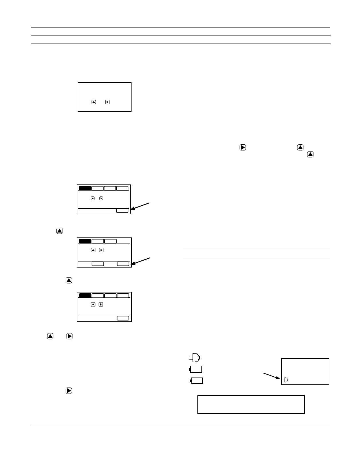
Power Indicators
• On the SUBMENU screen tab over to the EXIT tab and
• To set the passcode, hold and tap and then use the
• Hold and tap again to return to the THIRD MENU
• Tab to EXIT, and then hold and tap to return to the
To change the number of decimal places in the total
• To set the decimal point, hold and tap on SETD and then
• Hold and tap again to return to the THIRD MENU screen.
• Tab to EXIT, and then hold and tap to return to the
SAMP
HPOLL FOUT EXIT
tap the ve times. The THIRD MENU screen will
display.
SETD
+
PDAMP
TO
SET
FOUT EXIT
TEST
SETCD
000000
PRESS
PASSCODE
AMP
S
and to enter the new code.
screen
SUBMENU.
use the to move the decimal point.
SUBMENU.
A power indicator is displayed in the lower left of the main
display window.
Any meter powered from an external power source will
display a power plug icon when running on external power.
If the connection to external power is lost, the meter will
switch to the backup battery and the power icon will switch
to a battery symbol.
OK on the battery indicator means battery voltage is above
6.4 volts.
LO on the battery indicator means the battery is low and
should be replaced soon.
Beingpoweredbyexternal
DCorAC
Beingpoweredbybatteryvoltageissucient
Beingpoweredbybattery-
voltageislow
100
FORWARD TOTA
P
If display reads, ‘BATT END’
replace battery immediately.
Page 21
TOTAL
CU FT
X1000
RATE
GPM
Page 22

TROUBLESHOOTING & ERROR MESSAGES
Troubleshooting
Troubleshooting
Problem Probable Causes Things to try…
Blank Display Faulty wiring from power source to
Flow rate reading uctuates
excessively when ow is
unchanging
Flow Rate appears correct but
pulse/ frequency output is low,
erratic or absent
Flow Rate appears correct
but pulse/frequency output is
erratic and/or too high
meter
Backup battery has not been plugged in Plug in the battery
Dead backup battery Replace battery
Excessively turbulent or unsteady ow
due to partially closed valves or other
ow obstructions
Pipe not full Provide back pressure or other means to ensure
Pulsing ow due to combining multiple
upstream ow sources
Insucient mixing of upstream
chemicals
Low uid conductivity < 20 µS/cm Replace with dierent type of meter
Noisy electrical environment Improve grounding at meter and nearby potentially
Defective or noisy AC switching power
supply
Wiring incorrect Compare wiring with appropriate wiring
External device input impedance too low Use sourcing rather than sinking interface
Cable too long Reduce interface pull-up resistance
Electrical noise sources interfering with
pulse frequency signal
Check for incorrect wiring. Measure voltage with
DMM where red and black wires connect to
terminal block TB1 on back side of display. Verify
correct polarity and conrm that voltage is steady
and between 9Vdc and 32Vdc
Eliminate or minimize causes of ow disturbances
or increase meter damping
pipe is lled
Move connection point further upstream
Move chemical injection downstream from meter
noisy electrical equipment. Increase distance
between meter and electrical noise sources.
Replace power supply
recommendations
connection
Isolate, remove or reduce noise sources. Move
meter control cable away from noise sources.
Increase pulse damp setting (PDAMP)
FMG490 INSTRUCTIONS
Wrong type of cable Use only twisted pair cable and ensure both signal
Grounding problem Improve or try dierent grounding method
wires are on same twisted pair
Error Messages
Under certain conditions an error message may be displayed.
Message Description Notes
INIT Initialization is occurring during power up.
EMPTY PIPE Fluid is not detected between the sensing electrodes. Loop output = 22.8mA
LO in battery icon Battery is getting low, replace soon. Meter still functions. Above 6.4V, OK appears in icon
BATT END Battery is very low (approx. 6.1V). Totalizer stops updating. Loop output = 4mA
LOW VOLT Incoming external power is very low and backup battery is dead
or not connected
COIL FAIL Coil current too high or too low (short or open). Loop output = 22.8mA
COMM FAIL Communication between transmitter and sensor board fails. Loop output = 22.8mA
OVER RANGE Rate exceeds number of digits that can be displayed. Adjust units. Loop output = 4mA
Page 22
Loop output = 4mA
Page 23

FMG490 INSTRUCTIONS
WARRANTY/DISCLAIMER
OMEGA ENGINEERING, INC. warrants this unit to be free of defects in materials and workmanship for a
period of 13 months from date of purchase. OMEGA’s WARRANTY adds an additional one (1) month
grace period to the normal one (1) year product warranty to cover handling and shipping time. This
ensures that OMEGA’s customers receive maximum coverage on each product.
If the unit malfunctions, it must be returned to the factory for evaluation. OMEGA’s Customer Service
Department will issue an Authorized Return (AR) number immediately upon phone or written request.
Upon examination by OMEGA, if the unit is found to be defective, it will be repaired or replaced at no
charge. OMEGA’s WARRANTY does not apply to defects resulting from any action of the purchaser,
including but not limited to mishandling, improper interfacing, operation outside of design limits,
improper repair, or unauthorized modification. This WARRANTY is VOID if the unit shows evidence of
having been tampered with or shows evidence of having been damaged as a result of excessive corrosion;
or current, heat, moisture or vibration; improper specification; misapplication; misuse or other operating
conditions outside of OMEGA’s control. Components in which wear is not warranted, include but are not
limited to contact points, fuses, and triacs.
OMEGA is pleased to offer suggestions on the use of its various products. However,
OMEGA neither assumes responsibility for any omissions or errors nor assumes liability for
any damages that result from the use of its products in accordance with information provided
by OMEGA, either verbal or written. OMEGA warrants only that the parts manufactured by the
company will be as specified and free of defects. OMEGA MAKES NO OTHER WARRANTIES OR
REPRESENTATIONS OF ANY KIND WHATSOEVER, EXPRESSED OR IMPLIED, EXCEPT THAT OF
TITLE, AND ALL IMPLIED WARRANTIES INCLUDING ANY WARRANTY OF MERCHANTABILITY
AND FITNESS FOR A PARTICULAR PURPOSE ARE HEREBY DISCLAIMED. LIMITATION OF
LIABILITY: The remedies of purchaser set forth herein are exclusive, and the total liability of
OMEGA with respect to this order, whether based on contract, warranty, negligence,
indemnification, strict liability or otherwise, shall not exceed the purchase price of the
component upon which liability is based. In no event shall OMEGA be liable for
consequential, incidental or special damages.
CONDITIONS: Equipment sold by OMEGA is not intended to be used, nor shall it be used: (1) as a “Basic
Component”
applications or used on humans. Should any Product(s) be used in or with any nuclear installation or
activity, medical application, used on humans, or misused in any way, OMEGA assumes no responsibility
as set forth in our basic WARRANTY/D
OMEGA and hold OMEGA harmless from any liability or damage whatsoever arising out of the use of the
Product(s) in such a manner.
under 10 CFR 21 (NRC), used in or with any nuclear installation or activity; or (2) in medical
ISCLAIMER language, and, additionally, purchaser will indemnify
RETURN REQUESTS/INQUIRIES
Direct all warranty and repair requests/inquiries to the OMEGA Customer Service Department.
BEFORE RETURNING ANY PRODUCT(S) TO OMEGA, PURCHASER MUST OBTAIN AN AUTHORIZED
RETURN (AR) NUMBER FROM OMEGA’S CUSTOMER SERVICE DEPARTMENT (IN ORDER TO AVOID
PROCESSING DELAYS). The assigned AR number should then be marked on the outside of the return
package and on any correspondence.
The purchaser is responsible for shipping charges, freight, insurance and proper packaging to prevent
breakage in transit.
FOR WARRANTY RETURNS, please have the
following information available BEFORE contacting
OMEGA:
1. Purchase Order number under which the product
was PURCHASED,
2. Model and serial number of the product under
warranty, and
3. Repair instructions and/or specific problems
relative to the product.
OMEGA’s policy is to make running changes, not model changes, whenever an improvement is possible. This affords
our customers the latest in technology and engineering.
OMEGA is a trademark of OMEGA ENGINEERING, INC.
© Copyright 2019 OMEGA ENGINEERING, INC. All rights reserved. This document may not be copied, photocopied,
reproduced, translated, or reduced to any electronic medium or machine-readable form, in whole or in part, without the
prior written consent of OMEGA ENGINEERING, INC.
FOR NON-WARRANTY REPAIRS,
OMEGA for current repair charges. Have
the following information available BEFORE
contacting OMEGA:
1. Purchase Order number to cover the COST
of the repair,
2. Model and serial number of the product, and
3. Repair instructions and/or specific problems
relative to the product.
Page 23
consult
Page 24
Where Do I Find Everything I Need fo
r
Process Measurement and Control?
OMEGA…Of Course!
Shop online at omega.com
TEMPERATURE
Thermocouple, RTD & Thermistor Probes, Connectors, Panels & Assemblies
Wire: Thermocouple, RTD & Thermistor
Calibrators & Ice Point References
Recorders, Controllers & Process Monitors
Infrared Pyrometers
PRESSURE, STRAIN AND FORCE
Transducers & Strain Gages
Load Cells & Pressure Gages
Displacement Transducers
Instrumentation & Accessories
FLOW/LEVEL
Rotameters, Gas Mass Flowmeters & Flow Computers
Air Velocity Indicators
Turbine/Paddlewheel Systems
Totalizers & Batch Controllers
FMG490 INSTRUCTIONS
pH/CONDUCTIVITY
pH Electrodes, Testers & Accessories
Benchtop/Laboratory Meters
Controllers, Calibrators, Simulators & Pump
Industrial pH & Conductivity Equipment
DATA ACQUISITION
Communications-Based Acquisition Systems
Data Logging Systems
Wireless Sensors, Transmitters, & Receivers
Signal Conditioners
Data Acquisition Software
HEATERS
Heating Cable
Cartridge & Strip Heaters
Immersion & Band Heaters
Flexible Heaters
Laboratory Heaters
ENVIRONMENTAL
MONITORING AND CONTROL
Metering & Control Instrumentation
Refractometers
Pumps & Tubing
Air, Soil & Water Monitors
Industrial Water & Wastewater Treatment
pH, Conductivity & Dissolved Oxygen Instruments
s
PL-OM-XXXXXr1.0-20191210
12/10/2019
M-5756/1219
 Loading...