

Page 1
®
1234.56 GPM
876543.21 >
User’s Guide
Shop online at
Flow
omega.com
TM
®
www.omega.com
e-mail: http://omegamanual.info
For latest information and
product manual visit
www.omegamanual.info.
ISO 9001
CERTIFIED
CORPORATE QUALIT Y
STAMFORD, CT
ISO 9002
CERTIFIED
CORPORATE QUALIT Y
MANCHESTER, UK
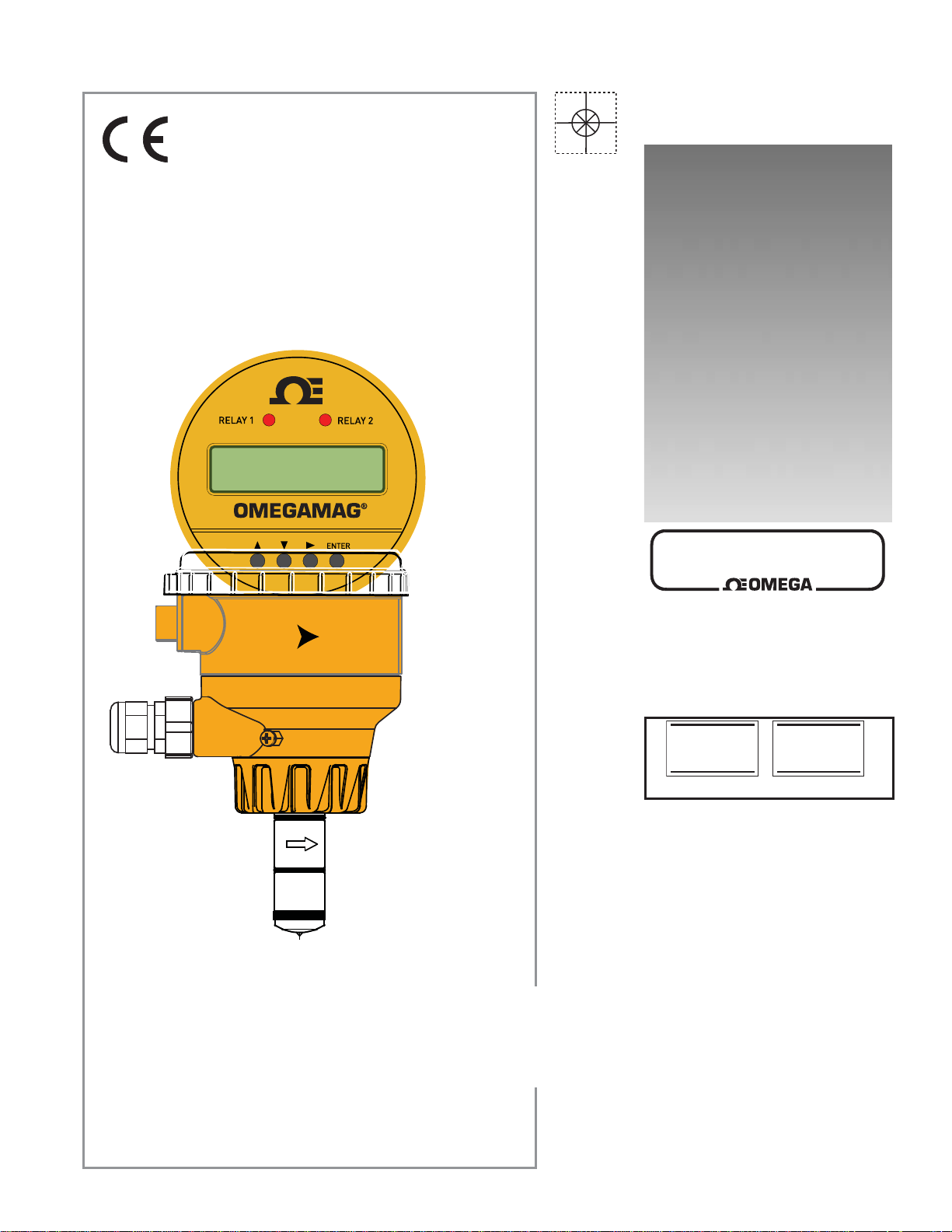
FMG-3000 SERIES Display Version
Magmeter
Page 2

omega.com
®
TM
OMEGAnet® Online Service
www.omega.com
Internet e-mail
Servicing North America:
USA: One Omega Drive, P.O. Box 4047
ISO 9001 Certifi ed Stamford CT 06907-0047
TEL: (203) 359-1660 FAX: (203) 359-7700
e-mail: [email protected]
Canada: 976 Bergar
For immediate technical or application assistance:
USA and Canada: Sales Service: 1-800-826-6342 / 1-800-TC-OMEGA
Customer Service: 1-800-622-2378 / 1-800-622-BEST
Engineering Service: 1-800-872-9436 / 1-800-USA-WHEN
TELEX: 996404 EASYLINK: 62968934 CABLE: OMEGA
Mexico: En Español: (001) 203-359-7803 FAX: (001) 203-359-7807
[email protected]
e-mail: [email protected]
®
®
®
Servicing Europe:
Benelux: Postbus 8034, 1180 LA Amstelveen, The Netherlands
TEL: +31 (0)20 3472121 FAX: +31 (0)20 6434643
Toll Free in Benelux: 0800 0993344
e-mail: [email protected]
Czech Republic: Rudé arm
France: 11, rue Jacques Cartier, 78280 Guyancourt, France
TEL: +33 (0)1 61 37 29 00 FAX: +33 (0)1 30 57 54 27
Toll Free in France: 0800 466 342
e-mail: [email protected]
Germany/Austria: Daimlerstrasse 26, D-75392 Deckenpfronn, Germany
TEL: +49 (0)7056 9398-0 FAX: +49 (0)7056 9398-29
Toll Free in Germany: 0800 639 7678
e-mail: [email protected]
United Kingdom: One Omega Drive, River Bend Technology Centre
ISO 9002 Certifi ed Northbank, Irlam, Manchester
M44 5BD United Kingdom
TEL: +44 (0)161 777 6611 FAX: +44 (0)161 777 6622
Toll Free in United Kingdom: 0800-488-48
e-mail: [email protected]
.
dy 1868, 733 01 Karvin. 8
It is the policy of OMEGA to comply with all worldwide safety and EMC/EMI regulations that apply.
OMEGA is constantly pursuing certifi cation of its products to the European New Approach Directives.
OMEGA will add the CE mark to every appropriate device upon certifi cation.
The information contained in this document is believed to be correct, but OMEGA Engineering, Inc. accepts
no liability for any errors it contains, and reserves the right to alter specifi cations without notice.
WARNING: These products are not designed for use in, and should not be used for, patient-connected applications.
Page 3
3000 Series OMEGAMAG® Display Version
6-2551.090-1-OM Rev. D 3/12
Topic: Page
1. Description 1
2. Specifi cations 2
3. Installation: Pipe fi ttings 3
4. Overview of Display versions 4
5. Wiring 5
6. View Menu 7
7. Setup Menu 9
Topic: Page
8. Calibration Menu 11
9. Relay Menus 19
10. Test Menu 16
11. Options Menu 16
12. Technical Information 17
13. Ordering Information 20
1.0 Description
The OMEGAMAG® measures the fl ow rate in a full pipe by monitoring the voltage produced when the (conductive) fl uid moves through
a magnetic fi eld.
Output options include a traditional frequency signal and a 4 to 20 mA output.
The OMEGAMAG® is available in two sizes that will accommodate pipes from ½ inch through 8 inch diameters.
Select from three different material combinations to match the magmeter to the application requirements.
SAFETY INSTRUCTIONS
1. Depressurize and vent system prior to installation or removal.
2. Confi rm chemical compatibility before use.
3. Do not exceed maximum temperature/pressure specifi cations.
4. Wear safety goggles or faceshield during installation/service.
5. Do not alter product construction.
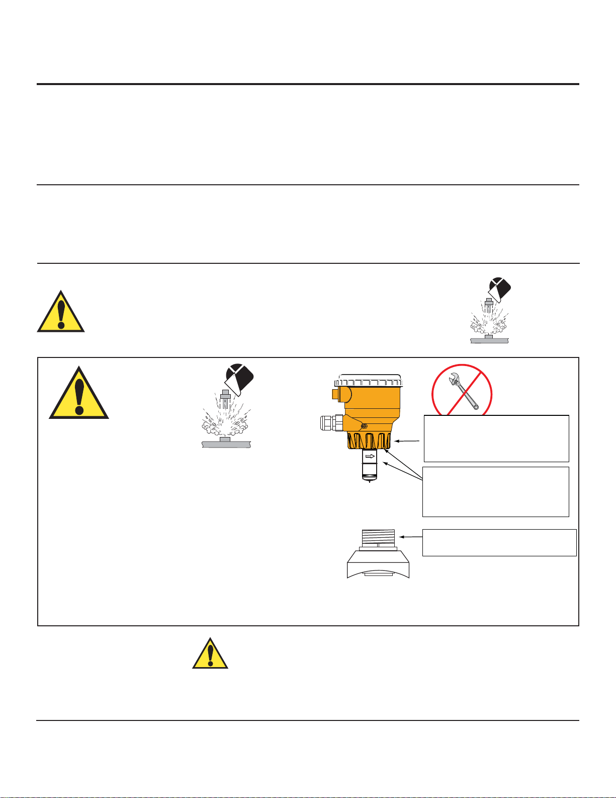
WARNING!
FAILURE TO FOLLOW THESE INSTRUCTIONS MAY RESULT
IN THE SENSOR BEING EJECTED FROM THE PIPE!
• DO NOT USE ANY TOOLS ON THE RETAINING CAP.
HAND TIGHTEN ONLY.
• LUBRICATE O-RINGS WITH A NON-PETROLEUM BASED,
VISCOUS LUBRICANT (GREASE) COMPATIBLE WITH
THE SYSTEM.
• DO NOT USE THREAD SEALANT OR LUBRICANTS ON
THE RETAINING CAP OR ON THE PLASTIC FITTING
THREADS.
• IF LEAKING IS OBSERVED FROM THE RETAINING
CAP, IT INDICATES DEFECTIVE OR WORN O-RINGS ON THE SENSOR. DO NOT ATTEMPT TO CORRECT BY
FURTHER TIGHTENING.
Chemical Compatibility Warning
The retaining nuts of Magmeters are not designed for prolonged contact with aggressive substances. Strong acids, caustic substances
and solvents or their vapor may lead to failure of the retaining nut, ejection of the sensor and loss of the process fl uid with possibly
serious consequences, such as damage to equipment and serious personal injury. Retaining nuts that may have been in contact with
such substances e.g. due to leakage or spilling, must be replaced.
Do not use any tools to
tighten the yellow retaining cap.
DO NOT USE thread sealant or
lubricants on retaining cap!
Lubricate O-rings with a
non-petroleum based, viscous
lubricant (grease) compatible
with the system.
DO NOT USE thread sealant
or lubricants on the fitting threads!
Environmental Recommendations:
• When used properly, this product presents no inherent danger to the environment.
• Please follow local ordinance when disposing of this or any product with electronic components.
1
Page 4
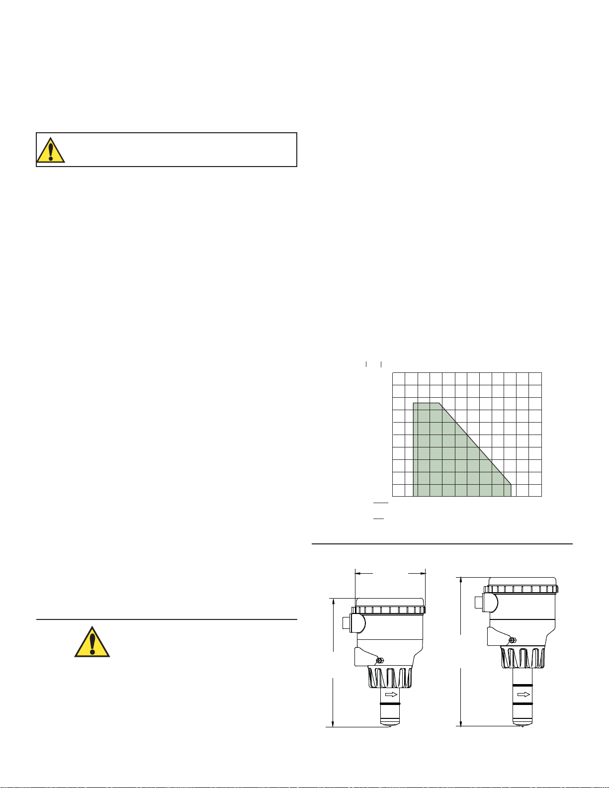
95.3 mm/
3.75 in.
174.5 mm/
6.87 in.
207.5 mm/
8.17 in.
Magmeter w/Display
for ½ in. to 4 in. pipe
Magmeter w/Display
for 5 to 8 in. pipe
2.0 Specifi cations
Wetted Materials:
• Sensor body and Electrodes and Grounding ring:
• PP-D: Polypropylene and 316 SS
• PVDF-D-HA: PVDF and Titanium
• PVDF and Hast-C: PVDF and Hastelloy-C
• O-rings: FPM (standard)
EPDM, Perfl uoroelastomer (optional)
The user is responsible for determining the chemical
suitability of these materials for a specifi c application.
• Case: PBT
• Display window: Polyamide
Power Requirements
• 4 to 20 mA: 21.6 to 26.4 VDC, 22.1 mA max.
400 mV p-p maximum ripple voltage
• Frequency: 5 to 26.4 VDC, 15 mA max.
• Digital: 5 to 6.5 VDC, 15 mA max.
• Auxiliary (only required for units with relays):
9 to 24 VDC, 0.4A max
• Reverse polarity and short circuit protected
Performance
• Pipe size range: DN15 to DN900 (½ to 36 in.)
• Flow Range Minimum: 0.05 m/s (0.15 ft/s)
(Bi-directional) Maximum: 10 m/s (33 ft/s)
• Linearity: ±1% of reading +0.01 m/s (0.033 ft/s)
• Repeatability ±0.5% of reading @ 25 °C (77 °F)
• Minimum Conductivity: 20 μS/cm
Relay Specifi cations
• Relay 1 and 2 Type: Mechanical SPDT
Rating: 5 A @ 30 VDC max., 5 A @ 250 VAC max.
• Relay 3 Type: Solid State
Rating: 50 mA @ 30 VDC, 50 mA @ 42 VAC
Hysteresis: Adjustable, plus timer delay
Trigger Delay: Adjustable (0 to 9999.9 sec.)
Relay Modes: Off, Low, High, Window, and Proportional Pulse
Relay Source: Flow Rate, Resettable Totalizer
Error Condition: Selectable; Fail Open or Fail Closed
Display
Characters: 2 x 16
Contrast: User-set in four levels
Backlighting (only on relay versions):
Requires external 9-24 VDC, 0.4 mA max.
Environmental
• Enclosure Rating : NEMA 4X/IP 65
• Storage Temperature: -20 to 70 °C (-4 to 158 °F)
• Relative Humidity: 0 to 95% (non-condensing)
• Operating Temperature
Ambient: -10 to 70 °C (14 to 158 °F)
Media: 0 to 85 °C (32 to 185 °F)
• Max. operating pressure: 10.3 bar @ 25 °C (150 psi @ 77 °F)
1.4 bar @ 85 °C (20 psi @ 185 °F)
bar
14
psi
200
2551
Pressure vs. Temperature
Output Specifi cations
Current Output (4 to 20 mA)
• Max Loop Resistance: 300
• Loop Accuracy: 32 μA max. error (25°C @ 24 VDC)
• Temp. drift: ±1 μA per °C max.
• Power supply rejection: ±1 μA per V
• Isolation: Low voltage <48 VAC/DC
from electrodes and aux power
• Maximum cable: 300 m (1000 ft.)
• Error condition: 22.1 mA
Frequency Output:
• Output modes: Freq, Freq÷10, or Mirror Relay 1
• Max. Pullup Voltage: 30 VDC
• Reverse Polarity Protected to -40 V
• Max. Current Sink: 50 mA, current limited
• Maximum cable: 300 m (1000 ft.)
Tests, Approvals & Standards
• CE
Chemical Compatibility Warning
The retaining nuts of Magmeters are not designed for prolonged
contact with aggressive substances. Strong acids, caustic
substances and solvents or their vapor may lead to failure of
the retaining nut, ejection of the sensor and loss of the process
fl uid with possibly serious consequences, such as damage to
equipment and serious personal injury. Retaining nuts that may
have been in contact with such substances e.g. due to leakage or
spilling, must be replaced.
Dimensions
160
11
120
8
80
6
40
3
Operating Pressure
°F
0 40 80 120 160 200
-18 4
°C
Media Temperature
2551
Acceptable
Media Range
27
49
71 93
240
115
2
Page 5
3. Installation: Pipe fi ttings
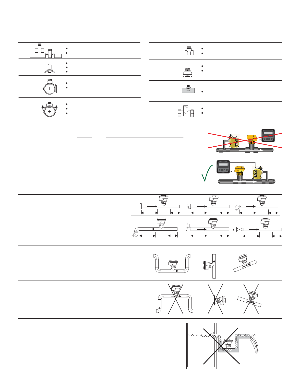
Omega offers a wide selection of installation fi ttings that control the position of the Magmeter electrodes in relation to the dimensions of
the pipe. You will fi nd a complete list of order numbers for installation fi ttings in the Calibration tables on pages 8-12.
Type Description
Plastic
tees
PVC
Glue-on
Saddles
0.5 to 2 inch versions
MPVC or CPVC
Available in 10 and 12 inch sizes only
Cut 2-1/2 inch hole in pipe
Weld in place using solvent cement
PVC
Saddles
2 to 4 inch, cut 1-7/16 inch hole in pipe
6 to 8 inch, cut 2-1/8 inch hole in pipe
Type Description
Iron, Carbon Steel,
316 SS Threaded
tees
Carbon steel &
stainless steel
Weld-on
Weldolets
Fiberglass
tees
FPT
Iron
Strap-on
saddles
2 to 4 inch, cut 1-7/16 inch hole in pipe
Over 4 inch, cut 2-1/8 inch hole in pipe
Special order 14 in. to 36 in.
Metric
Union
Fitting
3.1 Selecting a Location
• The magmeter requires a full pipe and a fully developed turbulent fl ow profi le for
accurate measurement.
• If the piping system harbors air pockets or bubbles, take steps to locate the sensor
so the air pockets will not contact the electrodes.
• In vertical installations, assemble the unit so the conduit ports are facing downward.
This prevents condensation inside the conduit from being directed into the
electronics housing.
• Chemical injection systems can temporarily alter the fl uid conductivity and cause
anomalies in the magmeter measurement.
To avoid this problem, install the Magmeter UPSTREAM of the injection point.
0.5 to 2 in. versions
Mounts on threaded pipe ends
2 to 4 inch, cut 1-7/16 inch hole in pipe
Over 4 inch, cut 2-1/8 inch hole in pipe
1.5 in. to 2 in. PVDF insert
For pipes from DN 15 to 50 mm
PP or PVDF
Flow 6.25 GPM
Total 1234567.8>
Signet Flow
Transmitter
Flow 6.25 GPM
Total 1234567.8>
Signet Flow
Transmitter
Flow
ENTER
Flow
ENTER
Select a location with suffi cient distance of
straight pipe immediately upstream of the
sensor.
Locating the sensor in a trap or where the fl ow
is upward helps to protect the sensor from
exposure to air bubbles when the system is in
operation.
These confi gurations are not recommended
because it is diffi cult to keep the pipe full.
3.2 Empty Pipe Detection
In a gravity-fl ow system, the tank must be designed
so the level does not drop below the outlet.
This causes the pipe to draw air in from the tank.
If air bubbles pass across the Magmeter electrodes,
the output will become erratic.
Inlet Outlet
Flange
10 x I.D. 5 x I.D.
2 x 90° Elbow
25 x I.D. 5 x I.D.
+GF+
+GF+
Reducer
15 x I.D. 5 x I.D.
2 x 90° Elbow
3 dimensions
40 x I.D. 5 x I.D.
+GF+
+GF+
90° Elbow
20 x I.D. 5 x I.D.
Valve/Pump
50 x I.D. 5 x I.D.
+GF+
+GF+
O.K.O.K. O.K.
+
F
G
+
GF
+GF+
+GF+
+
Vertical flow is OK IF the pipe remains full at all times.
+
GF
+
+GF+
+
+
G
F
+
3
Page 6
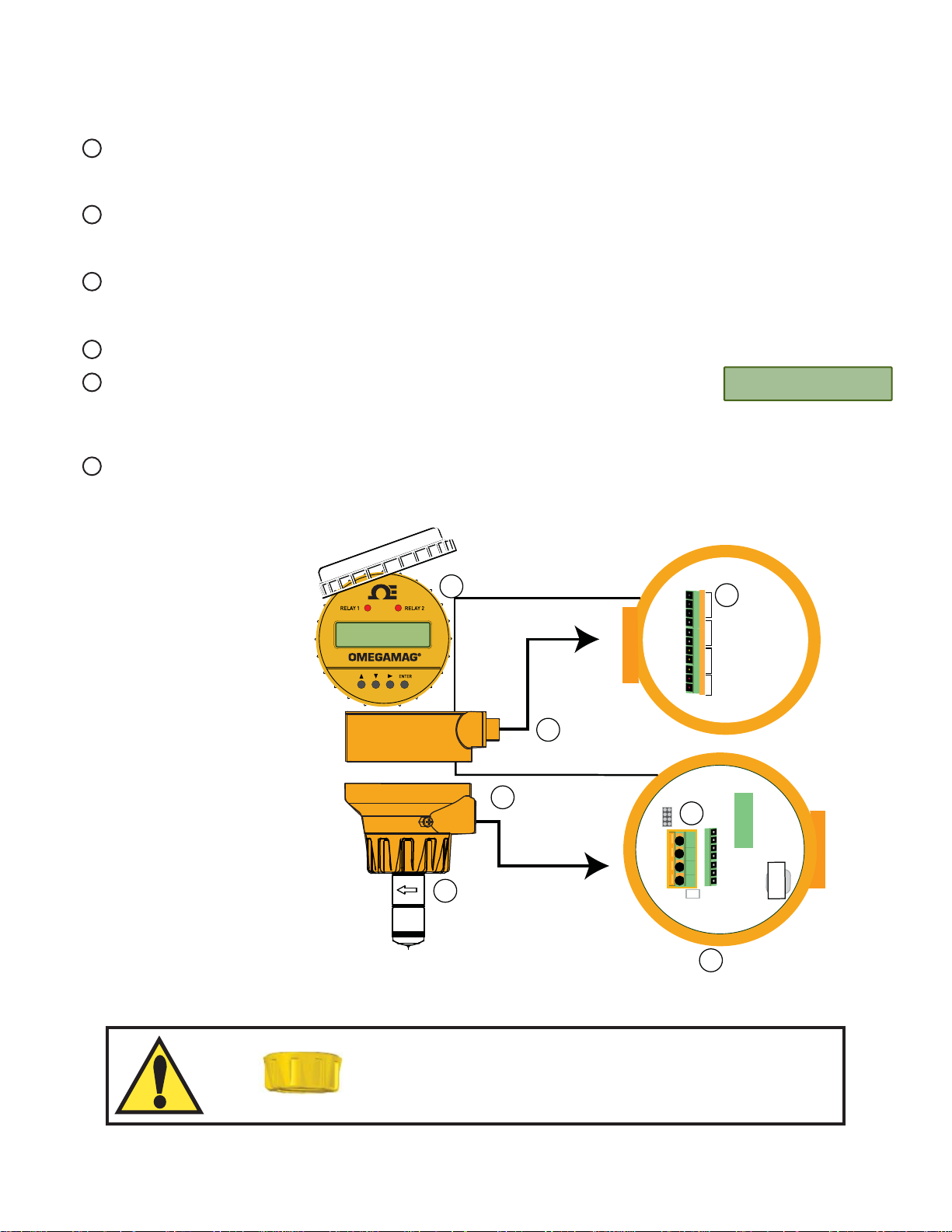
4.0 Overview of Display Magmeter
Display Magmeters use a dual-sided electronics module and dual conduit ports. Unused ports must be sealed to prevent corrosion and
moisture from entering the circuitry.
1 The lower set of conduit ports provide access to the wiring terminals for:
• Loop Power
• Flow Output Signal, whether it is a current loop, a frequency or the Mirror Relay 1 output.
2 The upper set of conduit ports provide access to the wiring terminals for:
• Relay output wiring
• Auxiliary power for relay coils and display backlight
3 The sensor is marked with a directional arrow to indicate the direction identifi ed as forward fl ow.
An adhesive decal is also provided that can be affi xed to the pipe to indicate the direction of forward fl ow.
Flow in the opposite direction from the arrow will be identifi ed as reverse fl ow on the display by a "-" symbol.
4 The terminals in the magmeter are designed to accomodate 14 to 22 AWG conductors.
5 The display includes two LEDs that light when Relay 1 or Relay 2 are activated.
• All three relays can be monitored by scrolling to the Relay Status display located in the View
English >
menu.
• If the Language option has not been made, new magmeters will always open with the Select Language display.
6 The part number, serial number and output type are identifi ed on the electronics module.
3.
5.
Relay Outputs
Auxiliary Power
2.
1.
4 to 20 mA Loop Out
Digital Out
Frequency Out
Mirror Relay 1 Out
NO1
NC1
NO2
NC2
NO3
NC3
4.
Relay 1
C1
Relay 2
C2
Relay 3
C3
V+
V-
Aux Pwr
4.
4
3
2
1
s/n 60604201234
60504201234
p/n 6-2551-11-OM
3-2551-11
4-20/freq out
®
420 GPM
123456.78 >
Language
6.
HAND-TIGHTEN THE THREADED NUT ONTO THE
INSTALLATION FITTING. DO NOT USE TOOLS!
DO NOT USE THREAD SEALANT OR LUBRICANTS
ON THE FITTING THREADS OR THE SENSOR CAP.
4
Page 7
5.0 Wiring
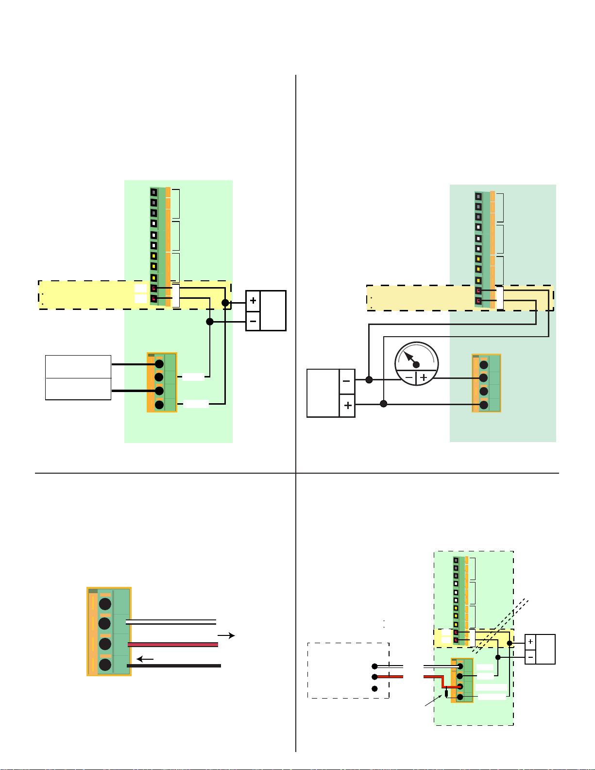
5.1 Basic Wiring
Frequency output
• FMG-3001, 3101 and 3201 OMEGAMAG
®
s may be
programmed to provide an open collector FREQUENCY
output.
• The maximum frequency output is 1000 Hz (@ 10 meters per
second)
• If the Frequency ÷ 10 output is selected, the maximum
frequency is 100 Hz (@ 10 meters per second)
• AUX PWR must be connected to power the display
backlighting and to power the relay coils if included.
NO1
Auxiliary Power for:
Display backlighting
Relay Coils
Ground
Signal
Frequency Out
Frequency ÷ 10 Out
NC1
C1
NO2
NC2
C2
NO3
NC3
C3
V+
V-
Magmeter
4
3
2
1
Relay 1
Relay 2
Relay 3
Aux Pwr
- VDC
+ VDC
VDC
5 to 26.4
4 to 20 mA output
FMG-3002, 3102 and FPM-3202 OMEGAMAG®s provide a
passive 4 to 20 mA loop output.
• External loop power (24 VDC) is required.
• Factory standard calibration is 4 to 20 mA = 0 - 5 m/s.
• The 4 to 20 mA output can be spanned to any range from
-10 m/s to +10 m/s.
• AUX PWR must be connected to power the display
backlighting and to power to the relay coils if included.
NO1
21.6 to
26.4 VDC
Auxiliary Power for:
Display backlighting
Relay Coils
4
20
4-20 mA Loop Output
NC1
C1
NO2
NC2
C2
NO3
NC3
C3
V+
V-
4
3
2
1
Magmeter
Relay 1
Relay 2
Relay 3
Aux Pwr
- VDC
+ VDC
5.2 Wiring: Mirror Relay 1 output
The FMG-3001, 3101 and 3201 OMEGAMAG
®
s can be
confi gured to provide an Open Collector output in lieu of the
sensor signal provided by Frequency output selection. The Open
Collector Output can be programmed via the Relay 1 menu.
Magmeter
Not used
4
Ground
3
Open Collector Out
2
1
5-24 VDC
®
5.3 The OMEGAMAG
and other manufacturer's instruments
When using the magmeter in a system with other manufacturer's
equipment, a pull-up resistor may be required to power the open
collector output.
NO1
Other Manufacturers
Flow Instrument
Ground
Frequency Input
5 to 24 VDC Out
Auxiliary Power for:
Display backlighting
Relay Coils
Sensr Gnd
(SHIELD)
Sensr IN
(RED)
10 KΩ
Pull-up Resistor
NC1
NO2
NC2
NO3
NC3
C1
C2
C3
V+
V-
Magmeter
Relay 1
Relay 2
Relay 3
Aux Pwr
4
Ground
Ground
3
Frequency Out
2
5 to 24 VDC
1
24 VDC
5
Page 8
NC3
y
C3
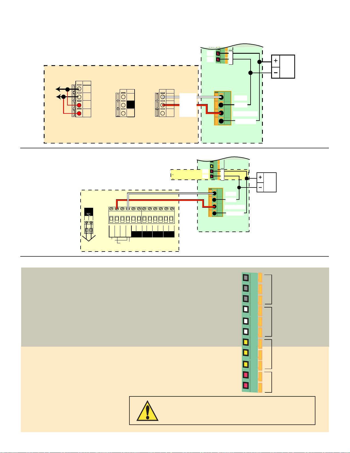
5.4 Wiring to Omega Flow Instruments
®
The OMEGAMAG
and FP90 series Flow Transmitters
When connecting the magmeter to any FP90 model Transmitter, the AUXILIARY power in the FP90 must always be connected.
V+
V-
To
FP90 Flow Transmitter
Aux Pwr
24 VDC
12 to 24 VDC
Power Source
System Pwr
4
Loop -
System Pwr
3
Loop +
AUX
2
Power -
AUX
1
Power +
Open Collector
Terminals 3-4: 4 to 20 Loop, Loop Power
Terminals 1-2: Auxiliary Power
6
5
Output
Output -
Output +
Sensor Input
from
Magmeter
Sensr Gnd
9
(SHIELD)
Sensr IN
8
(RED)
Sensr V+
7
(BLACK)
4
Ground
Ground
3
Frequency Out
2
5 to 24 VDC
1
Magmeter
The OMEGAMAG® and FPM5500
Rela
Aux Pwr
24 VDC
Auxiliary Power for:
Display backlighting
Relay Coils
C3
V+
V-
FPM5500, FPM9020A
12-24 V
10 W
+
-
+
AUX
output
Gnd
1
Total
reset
2
+
-
4-20
mA
12 to 24 V
10 W
Std. Sensor
Freq. IN
Freq. IN
+
Iso. Gnd
Sen. Pwr.
output
Open Collector
Sensor
Gnd
PLS
5.5 Wiring Relays
Relay 1, Relay 2 Type: Mechanical SPDT
Rating: 5A @ 30 VDC max., 5 A @ 250 VAC max
Relays 1 and 2 are dry contact relays rated for 5 A maximum current.
Relays 1 and 2 are best suited for switching high voltage loads, such as AC
powered pumps and valves.
When used to switch inductive loads, dry contact relays may be damaged by
arcing. Omega recommends the installation of a fi lter device to prevent such
damage.
FP90RC RC Filter kit (for relay use)
Relay 3 Type: Solid State
Rating: 50 mA @ 30 VDC, 50 mA @ 42 VAC
Relay 3 is a solid state relay. It can be applied exactly the same as a dry
contact relay, but the current rating is 0.2 A (200 mA) maximum. Relay 3 is
best suited to pulse applications and low voltage loads.
4
3
2
1
Magmeter
Ground
Ground
Frequency Out
5 to 24 VDC
NO1
NC1
C1
NO2
NC2
C2
NO3
NC3
C3
V+
V-
Relay 1
Mechanical Relays:
5 A @ 250 VAC
5 A @ 30 VDC
Relay 2
Solid State Relay 3:
50 mA max @ 30 VDC
Relay 3
50 mA max @ 42 VAC
Auxiliary Power
9 to 24 VDC
0.4 A Maximum
Relay Terminal Legend:
NO: Normally Open
NC: Normally Closed
C: Common
6
Auxiliary power must be connected to operate the relays and to
power the display backlighting. Auxiliary power is fully isolated.
The Loop Power supply may be used for Aux power if the power
source provides a suffi cient current rating.
Page 9
6.0 View Menu
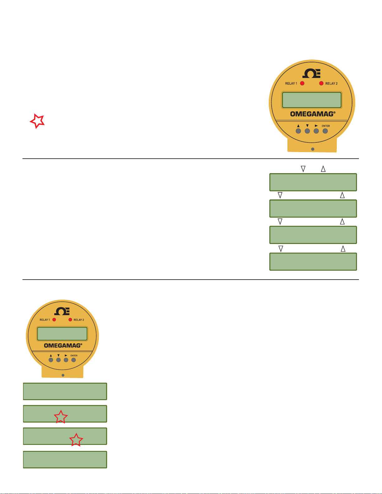
The VIEW menu contains all of the basic information available from the magmeter.
• The normal operating display shows the FLOW RATE on the top line of the display and the
resettable totalizer on the lower line of the display.
• The Right Prompt symbol (>) always indicates a sub-menu associated with the current
display. In this display it points the way to the TOTALIZER RESET function. See section 6.1
for detailed instructions.
• With AUXILIARY power connected to the magmeters with Relays, the display will be
backlit. There is no switch to turn the backlight off.
• A fl ashing character or text on the display indicates that the item is being edited. This
manual uses a (red) star to illustrate a fl ashing display.
• The following information is viewed by scrolling UP or DOWN. These displays will remain in
the display for 10 minutes, then the normal operating display will return.
Show the permanent total. This totalizer cannot be reset.
Shows the current output. For 4 to 20 mA Output models only.
Relay States shown for units with a relay board.
®
1234.56 GPM
876543.21 >
Gallons
Perm 876543.21
Current Output
14.89 mA
Relay 1 2 3
Off Off Off
6.1 Resetting the Resettable Totalizer
®
1234.56 GPM
876543.21 >
1234.56 GPM
1. From the normal operating display, press the RIGHT arrow key.
876543.21 >
Enter Code
0000
Reset Total ?
2. The Resettable Totalizer can be confi gured to require the security code before allowing the
See section 11, Options Menu for instructions.
3. Press any arrow key to toggle the fl ashing selection from NO to YES.
Yes No
Enter menus from this display. See section 6.2.
reset. If the Total Reset set to "RESET OFF" this display will not appear.
>
Enter Menu
123456.78 GPM
000000.00 >
4. Press the ENTER key. The totalizer will reset to 000000.00 and the display will immediately
return to the normal operating display.
7
Page 10
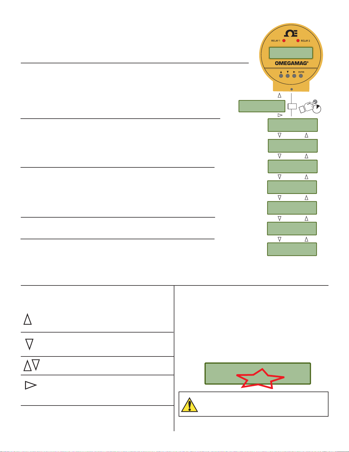
6.2 Navigating the Menus
Normal Operation Display
The normal operating display shows the Flow Rate on the top line and the Resettable Totalizer
on the bottom line.
• All menu instructions in this manual assume that the instrument is showing this display.
Menu Directory
The magmeter uses seven main menus to provide access to the calibration and programming
features. Each menu serves a specifi c function.
Starting from the normal operating display, there are two ways to access the menus:
1. Press the UP arrow key to scroll to the Enter Menu display, then press the RIGHT arrow
key.
2. Press the ENTER key and hold it for about three seconds.
Setup Menu
This menu contains all of the settings and information that the magmeter requires to
operate, including the K-Factor, the totalizer settings, low fl ow cutoff, and several display
characteristics. See section 7.0 for details related to this menu.
Calibration Menu
The Calibration menu provides two different methods for adjusting the calibration. See section
8.0 for details related to this menu.
Relay Menus
Each of the available relays in the FMG3001 and FMG3002 are programmed from their own
dedicated menu. See section 9 for details related to these menus.
Note: Menu items associated with Relay 2 and Relay 3 are suppressed in models without
relays. See section 9.0 for details related to this menu.
1234.56 GPM
876543.21 >
Enter Menu
>
Enter Menu
Setup >
Enter Menu
Calibration >
Enter Menu
Relay 1 >
Enter Menu
Relay 2 >
Enter Menu
Relay 3 >
®
ENTER
Or
3s
Test Menu
The Test menu is used to manually toggle relays or to induce a known value out of the
4 to 20 mA terminals. See section 10.0 for details related to this menu.
Options Menu
The Options menu contains those settings and values that are usually programmed during the
initial installation, and then seldom modifi ed, including the SECURITY CODE (see section 6.4).
See section 11.0 for details related to the Options menu.
6.3 Keypad Functions
6.4 Security Code
The magmeter has a security code that can be programmed to
Scrolls UP through any menu.
If the display shows any fl ashing character or selection,
scrolls UP to the previous value or selection.
any four digit numerical value.
• The factory setting is 0-0-0-0.
• To program the security code go to the Options menu.
• The security code will be required to edit any of the items in
Scrolls DOWN through any menu.
If the display shows any fl ashing character or selection,
scrolls DOWN to the next value or selection.
the menus. It is required only once for each editing session.
• Record the custom security code here or in a safe location.
• If the security code is lost, contact your Omega service
center for instructions.
Press the UP and DOWN keys together to abandon any
unsaved edits and return to the previous display.
Opens the menu currently being displayed.
In Edit modes, advances the fl ashing character.
In menus with only two options (Yes or No, On or Off)
toggles between selections.
Security Code ______ ______ ______ ______
ENTER
Saves a new selection in any menu.
From Normal Operation display, jumps to fi rst selection in
Menu directory (when held for three seconds)
WRITE IT DOWN!
Enter Menu
Test >
Enter Menu
Options >
Enter Code
0000
8
Page 11
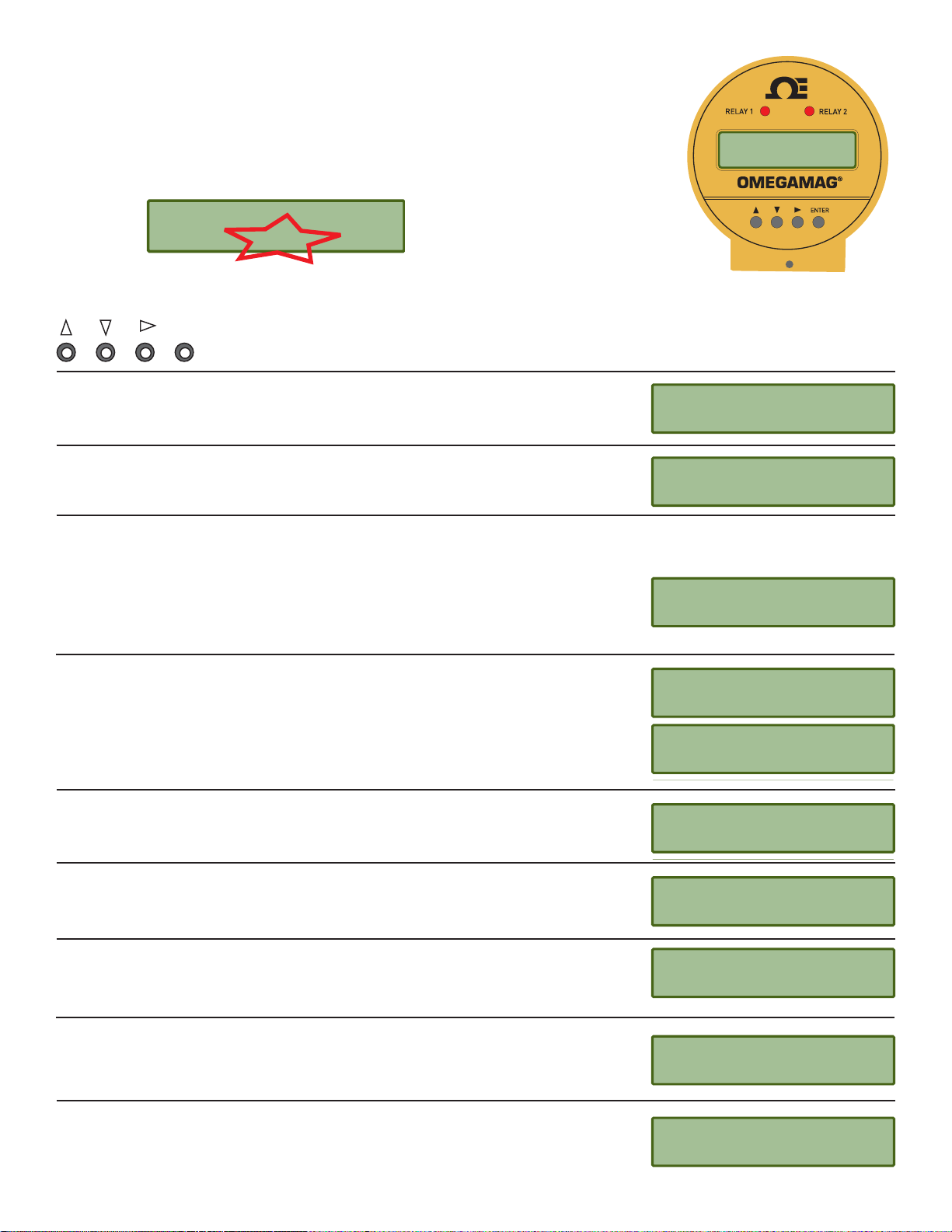
7.0 Setup Menu
The Setup menu contains all of the parameters necessary for the OMEGAMAG® to begin
measuring fl ow.
®
NOTE: The Security Code must be entered before any changes can be made to the Setup menu.
See the Options menu in section 11 for details.
Enter Menu
Setup >
Enter Code
0000
Use the keypad to navigate through each setting.
ENTER
K-Factor: See the charts in section 7.3 for values in pulses per U.S. Gallon or in pulses
per Liter. To use other units, convert the published values as appropriate.
The values shown for each menu item represent the factory
standard setting. All magmeters are packaged with these settings.
K-Factor
060.000 >
Pipe Size: Select the pipe size that is nearest to the nominal pipe size.
Pipe Size
2” DN50 >
Flow Units: Set the units for the application. Four characters are available. The fi rst three characters can be set to any symbol or
alpha character, upper or lower case. The following special symbols are located between the upper case and lower case menus:
• (centered dot) μ (micro) _ (blank)
- (dash) / (slash) 3 (for cubic units)
Flow Units
The last character selects the timebase for the fl ow rate measurement.
Select S/s (seconds) M/m (minutes), H/h (hours) or D/d (days)
GPM >
Set 4 mA: In the FMG3002 and FMG3102 versions only, set the fl ow rate where the current
output will be 4 mA.
Set 20 mA: In the FMG3002 and FMG3102 versions only, set the fl ow rate where the
current output will be 20 mA.
The 4 to 20 mA output may be spanned to monitor forward and reverse fl ow rates.
Total Factor: Set the factor by which the totalizer will count. This setting is made in the
application units (ie; gallons, liters, etc.).
Totalizer Units: Set the Totalizer Units. This setting serves as a label for the totalizer
displays only. It has no effect on the measurement. The special characters listed in the Total
Factor settings are available here also.
Low Flow Cutoff: Set a fl ow rate that the magmeter will use as a minimum threshhold. If
the fl ow rate falls below this value, the magmeter will respond as if the fl ow were zero.
Averaging: Set the averaging period based on the installation and fl ow conditions. Smaller
values allow the magmeter to respond to changes in fl ow rate quickly, while larger values
smooth the fl uctuations caused by installation and fl ow conditions. See section 7.1 for
details.
Sensitivity: Set a percentage of maximum range by which the fl ow must change to override
the averaging feature and "jump" quickly to the new fl ow rate. See detailed explanation in
section 7.1.
Set 4 mA
-100 GPM >
Set 20 mA
100.00 GPM >
Total Factor
1000.0 >
Totalizer Units
Gallons >
Low Flow Cutoff
0.5 GPM >
Averaging
25 secs >
Sensitivity
100% >
9
Page 12
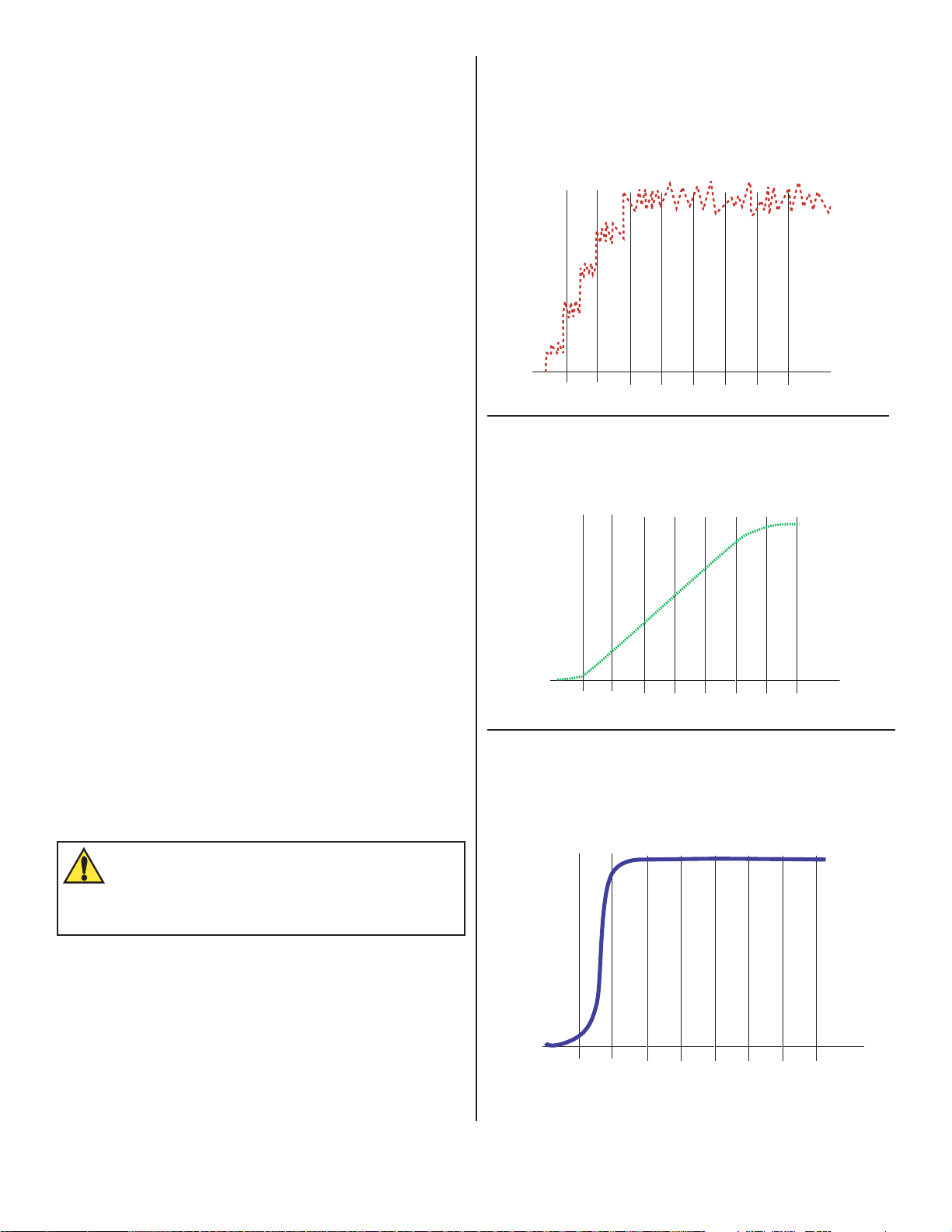
7.1 Averaging and Sensitivity
Even the most carefully engineered fl ow systems may experience
erratic and unstable conditions. If the instability is communicated
to the output functions, the results may create problems for
control devices.
To alleviate these issues, the magmeter provides two adjustments
that operate in tandem. The information here will help in
determining the appropriate settings for any specifi c application.
Averaging
• The AVERAGING setting dictates the time over which the
magmeter will average the fl ow signal.
The LCD display is updated every second. With averaging at
14 seconds, the fl ow rate on the display is an average of the
previous 14 seconds input.
Short averaging times provide the fastest display and output
response to changes in the fl ow rate.
Higher averaging times help to smooth the display and
current output where the fl ow in the pipe is erratic or unstable
due to installation limitations.
Sensitivity
• The SENSITIVITY setting determines how the magmeter
responds to sudden surges in the fl ow rate. It "overrides"
the Averaging function just long enough to allow an actual
change in fl ow rate to be displayed, then resumes the
averaging. The result is a smooth fl ow display and a quick
response to large shifts in the fl ow rate.
No Averaging
With AVERAGING set to zero, the fl ow rate will be displayed
immediately and with no fi ltering. This line represents the
actual output of the fl ow sensor as it responds to unstable fl ow
conditions in the pipe.
Velocity
Time
10 s 20 s 30 s 40 s 50 s 60 s 70 s
Averaging Only
With AVERAGING set to 50 seconds and SENSITIVITY still set to
zero the fl ow rate is stabilized, but a sharp change in fl ow rate is
not represented on the display or at the output for 50 seconds or
longer.
Velocity
The settings for Sensitivity represent a percentage of the
magmeter's maximum range, or 10 m/s.
Example: A sensitivity setting of 25% means that the fl ow rate
must change instantly and by more than 2.5 m/s before the
function is enabled.
NOTE: The SENSITIVITY function is ineffective if the Averaging
function is set to zero.
CAUTION
The SENSITIVITY function changes the response
characteristics of the magmeter. If used as part of a
tuned closed loop control system such a change may be
undesirable.
Time
10 s 20 s 30 s 40 s 50 s 60 s 70 s
Averaging and Sensitivity
With AVERAGING at 50 seconds and SENSITIVITY set to
25%, the fl ow rate is stabilized, while the sudden shift in fl ow is
refl ected very quickly.
Velocity
Time
10 s 20 s 30 s 40 s 50 s 60 s 70 s
10
Page 13
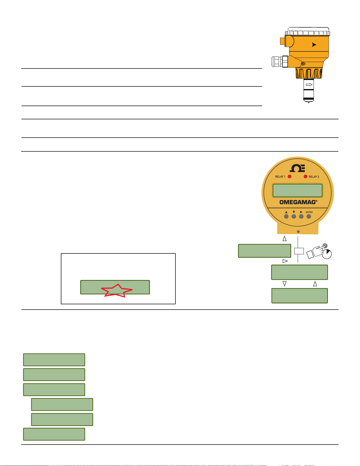
7.2 Bi-Directional Flow
• The magmeter is designed to measure bi-directional fl ow.
• The forward fl ow direction is indicated by the directional arrow molded into the side
Flow
of the magmeter sensor.
• The conduit ports are assembled at the factory to point UPSTREAM. They may be reversed by
disassembling the components of the magmeter and reassembling.
Flow Rate Display: The "+" sign is suppressed during forward fl ow.
"-123.45 GPM" during reverse fl ow.
Totalizer Display: The totalizer will count during forward fl ow conditions only.
During reverse fl ow the totalizer will not increment.
Relay Outputs: May be set to detect reverse fl ow: "Low Setpoint at -25GPM."
4 to 20 mA output: May be scaled to span any fl ow range:
For example: "4 to 20 mA = -100 GPM to +100 GPM"
Frequency output, Frequency ÷ 10 output: Reverse fl ow is processed same as forward fl ow in the frequency output magmeters.
8.0 Calibration Menu
The K-Factors published in this manual assume that the fl ow conditions in the pipe
are ideal.
®
Many factors that affect the fl ow rate are beyond the control of the magmeter;
variations in actual pipe dimensions, pipe smoothness, and other fl ow conditions
will contribute to the total system error.
1234.56 GPM
876543.21 >
Performing a custom calibration with the magmeter in place will adjust the K-factor
and can serve to compensate for installation conditions that may be less than ideal.
Select one of the calibration methods in this menu to achieve the most accurate
measurement possible in a specifi c application.
NOTE: The Security Code must be entered
before selecting the calibration method.
Enter Menu
>
Enter Menu
Or
ENTER
3s
Setup >
Enter Code
0000
Enter Menu
Calibration >
8.1 Volume Method Of Calibration
Use the volume method of calibration if the fl uid passing the magmeter can be measured by a volumetric method (as in a vessel of
known volume, or by weight). It requires the ability to pump a known volume of water past the magmeter, and then input the volume into
the magmeter program. It is most useful for small pipes and lower fl ow rates.
When performed properly, volumetric calibration is the most accurate method. For best results a fi ve minute test period is
recommended, and the test period should be no less than two minutes.
Press Enter
To S tart
Press Enter
To Stop
Enter Volume
000000. GPM
Value must be
more than 0.0
K-Factor
Out of Range
K-Factor
45.6789
At START, the magmeter begins counting the fl ow past the sensor.
At STOP, the magmeter stores the total fl ow accumulated since the START.
Enter the VOLUME that has been pumped past the sensor.
This error message appears if volume entered or the accumulated fl ow is zero. Repeat the test after
checking the system.
This message appears if the new K-Factor is less than 0.0001 or greater than 999999.
To correct the problem, perform the volumetric fl ow again, and be certain that the volume entered
is accurate.
Using the information from the VOLUME method, the magmeter will recalculate a new K-Factor. Press
ENTER to accept the new value, or use the keypad to adjust the value.
11
Page 14
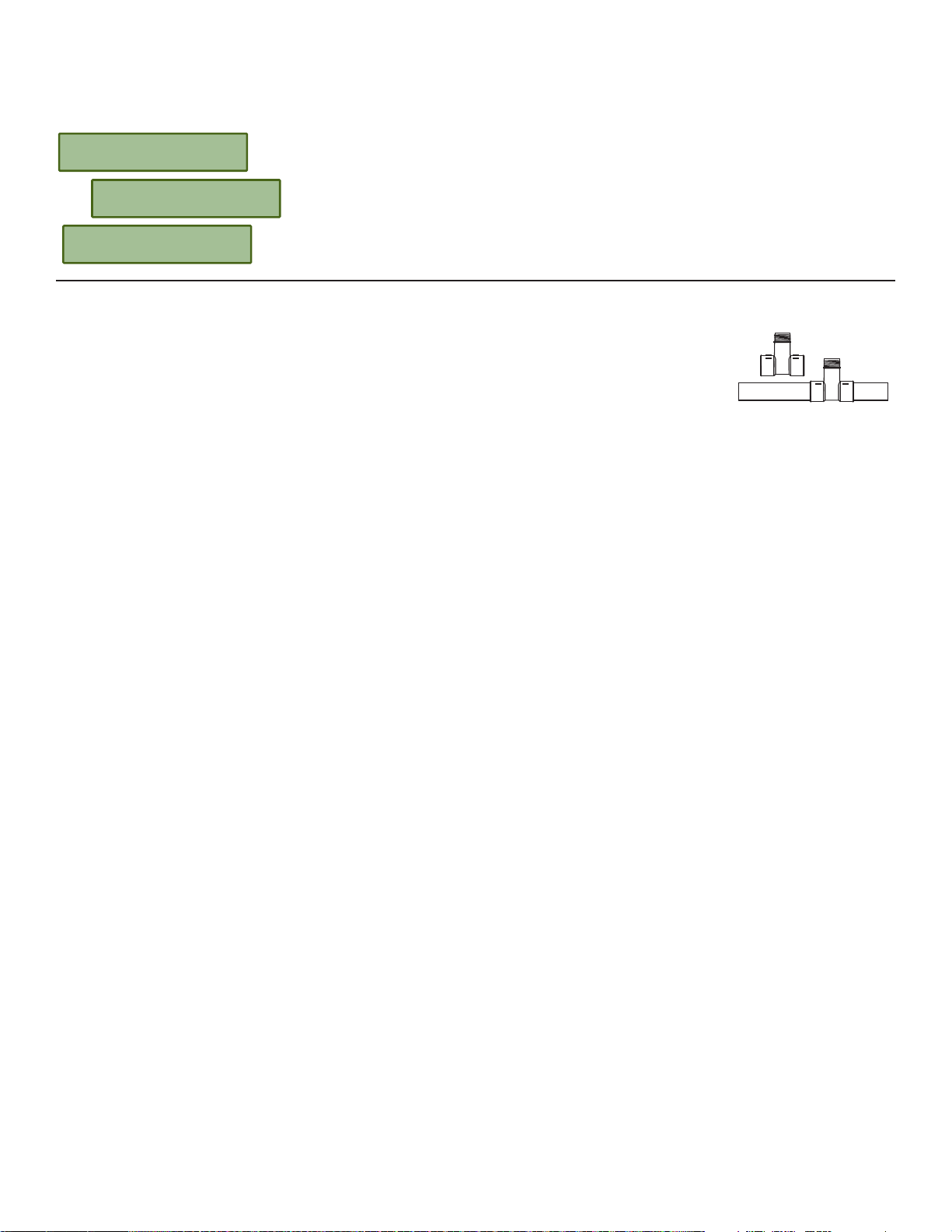
8.2 Rate Method Of Calibration
Use this method if the magmeter must be calibrated to match a reference fl ow meter. This is the method most commonly used by
monitoring agencies, and for large pipes where volumetric calibration is impractical. The accuracy of this calibration method is largely
dependent on the accuracy of the reference meter and the proximity of the reference to the magmeter.
Set New Flowrate
45.6789
K-Factor
Out of Range
The fl ow rate shown is based on the existing calibration of the magmeter.
Use the keypad to modify the fl ow rate to match the reference meter. The magmeter will
automatically calculate a new K-Factor based on the new fl ow rate.
This message appears if the new K-Factor is less than 0.0001 or greater than 999999.
To correct the problem, reexamine the fl ow rate and make certain it is accurate.
K-Factor
56.7890
Using the information from the RATE MATCHING method, the magmeter will recalculate a new
K-Factor. Press ENTER to accept the new value, or use the keypad to adjust the value.
8.3 Calibration Data: K-Factors* and Full Scale Current Values
Plastic Installation Fittings: PVC Tees and Saddles
PIPE SIZE FITTING K-Factor K-Factor 20 mA= 20 mA=
(IN.) TYPE Gallons Liters* in GPM in LPM
SCH 80 PVC TEES FOR SCH 80 PVC PIPE
½ FP-5305M 2277.00 601.58 13.10 49.60
¾ FP-5307M 1407.6 371.90 20.97 79.38
1 FP-5310M 861.17 227.52 34.21 129.50
1¼ FP-5312M 464.91 122.83 67.10 253.99
1½ FP-5315M 331.43 87.56 92.54 350.25
2 FP-5320M 192.89 50.96 145.15 549.38
SCH 80 PVC TEES FOR SCH 80 CPVC PIPE
½ FP-5305C 2277.0 601.58 13.18 49.87
¾ FP-5307C 1407.6 371.90 21.31 80.67
1 FP-5310C 861.17 227.52 34.84 131.86
1¼ FP-5312C 464.91 122.83 64.53 244.24
1½ FP-5315C 331.43 87.56 90.52 342.62
2 FP-5320C 192.89 50.96 155.53 588.70
SCH 80 PVC SADDLES FOR SCH 80 PVC PIPE
2 FP-5320S 193.83 51.21 154.77 585.81
2½ FP-5325S 138.01 36.46 217.38 822.78
3 FP-5330S 83.89 22.16 357.62 1353.60
4 FP-5340S 40.88 10.80 733.88 2777.74
6 FP-5360S 22.53 5.95 1331.85 5041.06
8 FP-5380S 12.52 3.31 2395.41 9066.64
10 FP-5381S 7.94 2.10 3778.75 14302.57
12 FP-5382S 5.71 1.51 5256.69 19896.57
SCH 80 PVC SADDLES FOR SCH 40 PVC PIPE
2 FP-5320S 180.01 47.56 166.66 630.81
2½ FP-5325S 123.72 32.69 242.49 917.82
3 FP-5330S 75.81 20.03 395.71 1497.76
4 FP-5340S 41.87 11.06 716.56 2712.19
6 FP-5360S 19.71 5.21 1521.92 5760.46
8 FP-5380S 11.73 3.10 2558.12 9682.50
10 FP-5381S 7.43 1.96 4037.60 15282.3
12 FP-5382S 5.23 1.38 5734.87 21706.48
12
Page 15

Plastic Installation Fittings for Metric Pipes:
Polypropylene True Union Tees
PVDF True Union Tees
PVC True Union Tees
PIPE SIZE FITTING K-Factor K-Factor 20 mA= 20 mA=
(IN.) TYPE Gallons Liters* in GPM in LPM
SCH 80 PVC TEES FOR SCH 80 PVC PIPE
½ FP-5305M 2277.00 601.58 13.10 49.60
¾ FP-5307M 1407.6 371.90 20.97 79.38
1 FP-5310M 861.17 227.52 34.21 129.50
1¼ FP-5312M 464.91 122.83 67.10 253.99
1½ FP-5315M 331.43 87.56 92.54 350.25
2 FP-5315M 192.89 50.96 145.15 549.38
SCH 80 PVC TEES FOR SCH 80 CPVC PIPE
½ FP-5305CM 2277.0 601.58 13.18 49.87
¾ FP-5307CM 1407.6 371.90 21.31 80.67
1 FP-5310CM 861.17 227.52 34.84 131.86
1¼ FP-5312CM 464.91 122.83 64.53 244.24
1½ FP-5315CM 331.43 87.56 90.52 342.62
2 FP-5320CM 192.89 50.96 155.53 588.70
SCH 80 PVC SADDLES FOR SCH 80 PVC PIPE
2 FP-5320S 193.83 51.21 154.77 585.81
2½ FP-5325S 138.01 36.46 217.38 822.78
3 FP-5330S 83.89 22.16 357.62 1353.60
4 FP-5340S 40.88 10.80 733.88 2777.74
6 FP-5360S 22.53 5.95 1331.85 5041.06
8 FP-5380S 12.52 3.31 2395.41 9066.64
10 FP-5381S 7.94 2.10 3778.75 14302.57
12 FP-5382S 5.71 1.51 5256.69 19896.57
SCH 80 PVC SADDLES FOR SCH 40 PVC PIPE
2 FP-5320S 180.01 47.56 166.66 630.81
2½ FP-5325S 123.72 32.69 242.49 917.82
3 FP-5330S 75.81 20.03 395.71 1497.76
4 FP-5340S 41.87 11.06 716.56 2712.19
6 FP-5360S 19.71 5.21 1521.92 5760.46
8 FP-5380S 11.73 3.10 2558.12 9682.50
10 FP-5381S 7.43 1.96 4037.60 15282.3
12 FP-5382S 5.23 1.38 5734.87 21706.48
13
Page 16

Metal Installation Fittings:
Carbon Steel Tees and Weld-olets
Stainless Steel Tees and Weldolets
Galvanized Iron Tees
PIPE SIZE FITTING K-Factor K-Factor 20 mA= 20 mA=
(IN.) TYPE Gallons Liters* in GPM in LPM
CARBON STEEL TEES ON SCH 40 PIPE
½ FM-5305CS 1572.66 415.50 19.08 72.20
¾ FM-5307CS 1086.73 287.11 27.61 104.49
1 FM-5310CS 582.34 153.86 51.52 194.99
1¼ FM-5312CS 377.48 99.73 79.48 300.81
1½ FM-5315CS 267.79 70.75 112.03 424.02
2 FM-5320CS 167.85 44.35 178.73 676.48
STAINLESS STEEL TEES ON SCH 40 PIPE
½ FMG-5305 1601.26 423.05 18.74 70.91
¾ FMG-5307 937.78 247.76 31.99 121.08
1 FMG-5310 606.18 160.15 49.49 187.32
1¼ FMG-5312 279.68 73.89 107.26 405.99
1½ FMG-5315 147.65 39.01 203.19 769.06
2 FMG-5320 111.90 29.56 268.09 1014.73
STAINLESS STEEL WELDOLETS ON SCH 40 PIPE
2½ FMG-5325 106.31 28.09 282.19 1068.10
3 FMG-5330 72.27 19.09 415.12 1571.25
4 FMG-5340 36.84 9.73 814.34 3082.28
4 FMG-5350 29.28 7.73 1024.70 3878.50
4 FMG-5360 20.29 5.36 1478.26 5595.21
8 FMG-5380 11.73 3.10 2557.72 9680.96
10 FMG-5381 7.45 1.97 4028.83 15249.1
12 FMG-5382 5.24 1.39 5722.73 21660.5
CARBON STEEL WELDOLETS ON SCH 40 PIPE
2½ FM-5325CS 105.70 27.93 283.82 1074.27
3 FM-5330CS 70.68 18.67 424.45 1606.56
4 FM-5340CS 36.38 9.61 824.65 3121.30
4 FM-5350CS 29.28 7.73 1024.70 3878.50
6 FM-5360CS 20.29 5.36 1478.26 5595.21
8 FM-5380CS 11.73 3.10 2557.72 9680.96
10 FP-5381CS 7.45 1.97 4028.83 15249.1
12 FP-5382CS 5.24 1.39 5722.73 21660.5
GALVANIZED IRON TEES ON SCH 40 PIPE
1 FP-5310GI 558.50 147.56 53.71 203.31
1¼ FP-5312GI 334.45 88.36 89.70 339.51
1½ FP-5315GI 248.97 65.78 120.49 456.07
2 FP-5320GI 146.00 38.57 205.48 777.76
14
Page 17

Metal Installation Fittings:
Bronze and Copper Tees and Brazolets
PIPE SIZE FITTING K-Factor K-Factor 20 mA= 20 mA=
(IN.) TYPE Gallons Liters* in GPM in LPM
BRONZE TEES ON SCH 40 PIPE
1 FP-5310BR 582.34 153.86 51.52 194.99
1¼ FP-5312BR 330.54 87.33 90.76 343.53
1½ FP-5315BR 254.76 67.31 117.76 445.71
2 FP-5320BR 157.36 41.58 190.64 721.58
COPPER TEES FITTING ON COPPER PIPE SCH K
½ FP-5305CU 2459.19 649.72 12.20 46.17
¾ FP-5307CU 1108.02 292.74 27.08 102.48
1 FP-5310CU 649.87 171.70 46.16 174.73
1¼ FP-5312CU 422.03 111.50 71.09 269.06
1½ FP-5315CU 281.43 74.35 106.60 403.47
2 FP-5320CU 136.02 35.94 220.55 834.78
COPPER TEES FITTING ON COPPER PIPE SCH L
½ FP-5305CU 2406.30 635.75 12.47 47.19
¾ FP-5307CU 1174.77 310.37 25.54 96.66
1 FP-5310CU 672.28 177.62 44.62 168.90
1¼ FP-5312CU 402.84 106.43 74.47 281.87
1½ FP-5315CU 294.99 77.94 101.70 384.92
2 FP-5320CU 149.63 39.53 200.50 758.89
COPPER/BRONZE BRAZOLET ON SCH 40 PIPE
2½ FP-5325BR 117.31 30.99 255.74 967.96
3 FP-5330BR 78.62 20.77 381.58 1444.28
4 FP-5340BR 45.13 11.92 664.77 2516.15
5 FP-5350BR 32.79 8.66 914.91 3462.95
6 FP-5360BR 22.73 6.01 1319.87 4995.72
8 FP-5380BR 13.14 3.47 2283.68 8643.71
10 FP-5381BR 8.34 2.20 3597.17 13615.29
12 FP-5382BR 5.87 1.55 5109.58 19339.76
Metal Installation Fittings:
Iron Saddles
PIPE SIZE FITTING K-Factor K-Factor 20 mA= 20 mA=
(IN.) TYPE Gallons Liters* in GPM in LPM
SCH 80 IRON SADDLE ON SCH 80 PIPE
2 FP-5320GIS 194.85 51.48 153.96 582.75
2½ FP-5325GI 142.28 37.59 210.86 798.10
3 FP-5330GI 87.53 23.13 342.72 1297.20
4 FP-5340GI 40.62 10.73 738.58 2795.54
5 FP-5350GI 29.28 7.74 1024.43 3877.48
6 FP-5360GI 22.30 5.89 1345.58 5093.03
8 FP-5380GI 12.52 3.31 2395.41 9066.64
10 FP-5381GI 7.94 2.10 3778.75 14302.5
12 FP-5382GI 5.65 1.49 5311.45 20103.8
SCH 80 IRON SADDLE ON SCH 40 PIPE
2 FP-5320GIS 185.35 48.97 161.85 612.61
2½ FP-5325GI 127.47 33.68 235.36 890.83
3 FP-5330GI 76.62 20.24 391.54 1481.99
4 FP-5340GI 40.23 10.63 745.72 2822.57
5 FP-5350GI 27.32 7.22 1098.24 4156.83
6 FP-5360GI 19.71 5.21 1521.92 5760.46
8 FP-5380GI 11.61 3.07 2584.23 9781.30
10 FP-5381GI 7.36 1.94 4078.8 15438.2
12 FP-5382GI 5.18 1.37 5793.39 21927.9
15
Page 18
9.0 Relay Menus
Magmeter models FMG-300X, 310X and 320X have two dry contact relays
(Relays 1 and 2) and one Solid State relay (Relay 3).
®
Any of these relays can be set to any of the operating modes listed below.
876543.21 >
The setpoint values for HIGH, LOW and WINDOW modes can be set to
negative values if required.
For example, a LOW alarm might be set to activate if the fl ow rate falls below
-10 GPM.
Negative values are not available for relays in PULSE or TOTAL modes.
Off: If a relay is not used, it can be turned Off to prevent contact wear.
Enter Menu
>
NOTE: The Security Code
must be entered before
Setup >
modifying the relay menu.
Enter Code
0000
Calibration >
Relay 1 >
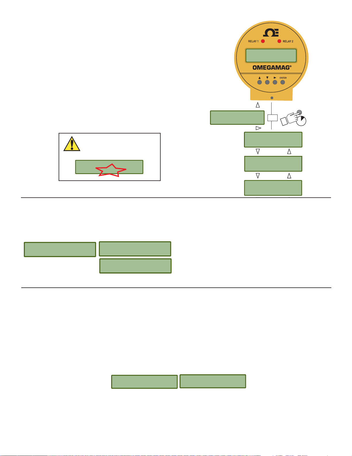
9.1 Pulse Relay mode
Program a relay to activate for a fi xed period, for each volume of fl uid that passes the sensor.
For example, program the relay to pulse once for 100 ms for every 3 gallons that pass by the sensor.
1234.56 GPM
ENTER
Or
3s
Enter Menu
Enter Menu
Enter Menu
Relay Volume: Set the volume of fl uid that the magmeter must
Relay 1 Mode
Pulse >
Relay 1 Volume
0.0000 Gal >
measure before activating the relay for one pulse.
Pulse Width: Adjust the length of time the relay will remain
Relay 1 Width
0.1 secs >
activated. The pulse width setting is dependent on the type of
external equipment being connected to the relay.
9.2 Total Relay mode
Program a relay to activate when the Resettable Totalizer reaches a specifi c value. The maximum setting is 999999.
Application example: A fi lter must be replaced in a reverse osmosis system every 10000 gallons. The service representative that installs
a new fi lter sets Relay 3 to Total mode, sets the setpoint at 10000 and resets the totalizer to 000000.00. When the totalizer is reset, the
relay will be deactivated and the process begins anew.
Every time the totalizer reaches 10000, the relay activates and lights a message indicator to remind the operator to contact the service
representative to replace the fi lter.
Relay 1 Mode
Total >
Relay 1 Set High
000000 >
16
Page 19
9.3 High, Low, or Window Relay modes
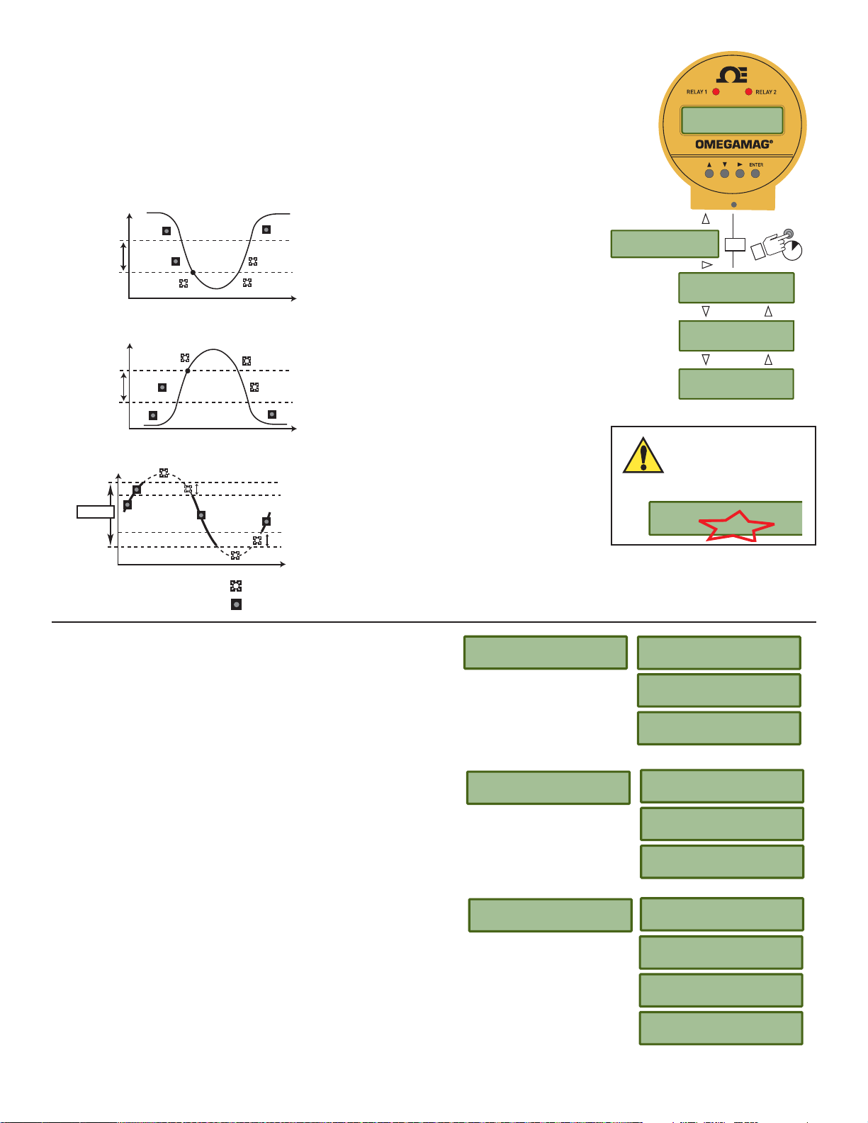
Program the relay to activate when the fl ow rate reaches a setpoint (High or Low) or when the fl ow
rate moves outside of a prescribed range (window).
Reverse Flow
The setpoint values for HIGH, LOW and WINDOW modes can be set to negative values if required.
For example, a LOW alarm might be set to activate if the fl ow rate falls to -10 GPM.
Process
Hysteresis
Relay behavior with LOW Setpoint
Low Setpoint
Time
1234.56 GPM
876543.21 >
Enter Menu
>
Enter Menu
Setup >
®
ENTER
Or
3s
Process
High Setpoint
Relay behavior with HIGH Setpoint
Hysteresis
Time
Process
High Limit
Window
Low Limit
Hysteresis
Relay behavior with WINDOW Setpoints
Hysteresis
Time
Relay activated
Relay deactivated
Set Low: Set the fl ow rate where a Low relay will be activated.
Set High: Set the fl ow rate where a High relay will be activated.
Set Window: Set a range where the relay will be deactivated. If
the fl ow rate moves outside of the low or high boundaries the
relay will be activated.
Enter Menu
Calibration >
Enter Menu
Relay 1 >
NOTE: The Security
Code must be entered
before modifying the
relay menu.
Enter Code
0000
The values shown for each menu item represent the factory
standard setting. All magmeters are packaged with these settings.
Relay 1 Mode
Low >
Relay 1 Set Low
00.000 GPM >
Relay 1 Hys
00.000 GPM >
Relay 1 Delay
0.1 secs >
Hysteresis: Set a fl ow rate increment where the relay will be
deactivated. The hysteresis setting serves to prevent relay
"chatter" when the fl ow rate recovers from an alarm condition by
requiring the fl ow rate to move substantially within the setpoint.
Example: If high setpoint is 100 GPM, and hysteresis is 5 GPM,
the relay will be activated if fl ow rate reaches 100.1 GPM, but will
only be deactivated when the fl ow rate is 95 GPM (5 GPM inside
the setpoint.)
Delay: Set a time period for the relay to wait after reaching the
setpoint. This delay serves to prevent the relay "chatter" by
allowing the fl ow rate time to move back within the setpoint.
Example: If the delay is set to 5 seconds, in the example above
the relay will not be activated until the fl ow rate exceeds 100 GPM
for 5 seconds.
Relay 1 Mode
High >
Relay 1 Mode
Window >
00.000 GPM >
00.000 GPM >
0.1 secs >
00.000 GPM >
00.000 GPM >
00.000 GPM >
0.1 secs >
The menu repeats for Relay 2 and Relay 3.
Relay 1 Set High
Relay 1 Hys
Relay 1 Delay
Relay 1 Set Low
Relay 1 Set High
Relay 1 Hys
Relay 1 Delay
17
Page 20
10.0 Test Menu
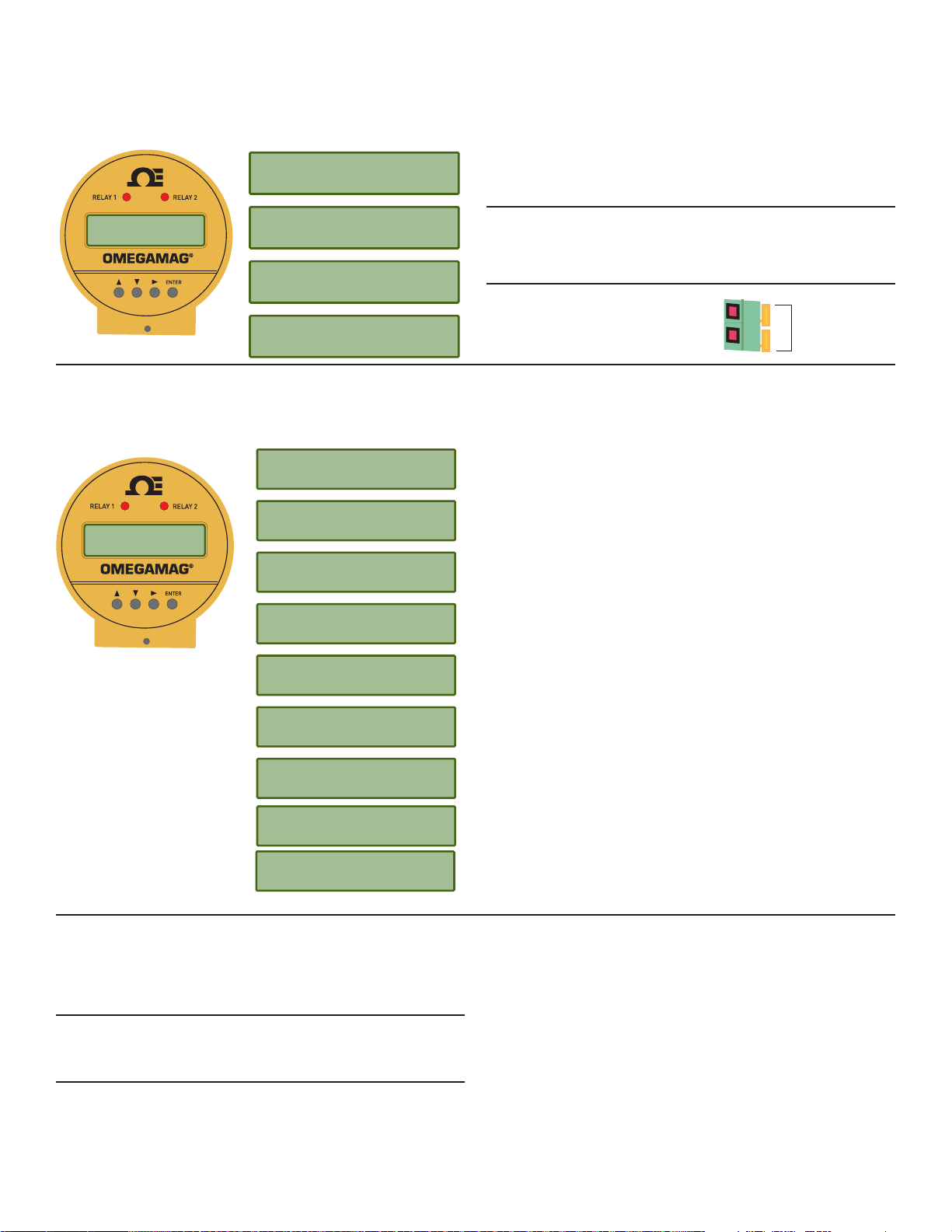
The Test menu provides a simple method to verify that the system is operating properly. Auxiliary power MUST be connected to the
magmeter to activate the relays
Shown for 4 to 20 mA models only.
Use the keypad to enter any current output from 4.0 mA minimum
to 22.1 mA maximum.
Shown for Relay models only
Toggle any of these relays ON and OFF to verify that the system
®
Enter Menu
Test >
Test Output
4.20 mA >
Test Relay 1
Open Closed >
is operating properly.
Test Relay 2
Open Closed >
Test Relay 3
Open Closed >
Auxiliary power MUST be
connected to the magmeter to
test the relays.
V+
Auxiliary Power
V-
9 to 24 VDC
0.4 A Maximum
11.0 Options Menu
The Options Menu contains those features and settings that will normally be set one time and then seldom changed. These include
language preference, decimal placement, Security Code assignment, etc.
®
Enter Menu
Options >
Language
English >
Security Code
**** >
Contrast
2 >
Select from English, German, French or Spanish.
This Selection will be displayed at fi rst power-up of a new magmeter.
Security Code can be set to any four digit number. Factory standard
setting is 0000.
Set for best view after the magmeter is installed. Larger number
means display appears darker.
Lock ON requires the Security Code before resetting the resettable
totalizer. Lock OFF reset with no security code.
Filters out common 50 or 60 Hz electrical noise.
Set the maximum resolution for the FLOW RATE display by limiting
the decimal to this point. The Flow Rate display will auto-scale from
this resolution up to whole units.
Set the maximum resolution for the TOTALIZER display by limiting
the decimal to this point. The Totalizer display will always show this
resolution.
Select decimal point or comma for use in numeric displays.
For Frequency/Digital models only: Select Freq output, Freq ÷ 10
output, Mirror Relay 1 output or Digital output.
The values shown for each
menu item represent the
factory standard setting. All
magmeters are packaged
with these settings.
Total Reset
Lock On >
Noise Rejection
60 Hz >
Flow Decimal
****.** >
Total Decimal
******.** >
Separator
ddd.d >
Output Mode
Frequency >
11.1 Output Modes
In FREQUENCY output mode, the OMEGAMAG
®
serves as a traditional fl ow sensor and provides an output pulse that is compatible
with most Omega POWERED fl ow instruments. It is not compatible with the FPM5800 Self-Powered Flow Meter or the FPM5750 series
Battery-powered fl ow totalizer. The frequency output range is from 0 Hz to 1000 Hz.
The FREQUENCY ÷ 10 output mode reduces the output frequency of the OMEGAMAG
®
to a range that is useful for some
programmable logic controllers (PLC). The frequency output range is from 0 Hz to 100 Hz. This shift does not affect the stated accuracy
of the magmeter's frequency output.
The MIRROR RELAY 1 output mode allows Frequency models to use the Open Collector Output like a relay that can be programmed
via the Relay 1 menu.
If the magmeter is equipped with relays, this mode will mirror the settings of Relay 1.
If the magmeter is not equipped with relays, this mode can still be selected and programmed via the Relay 1 menu.
18
Page 21
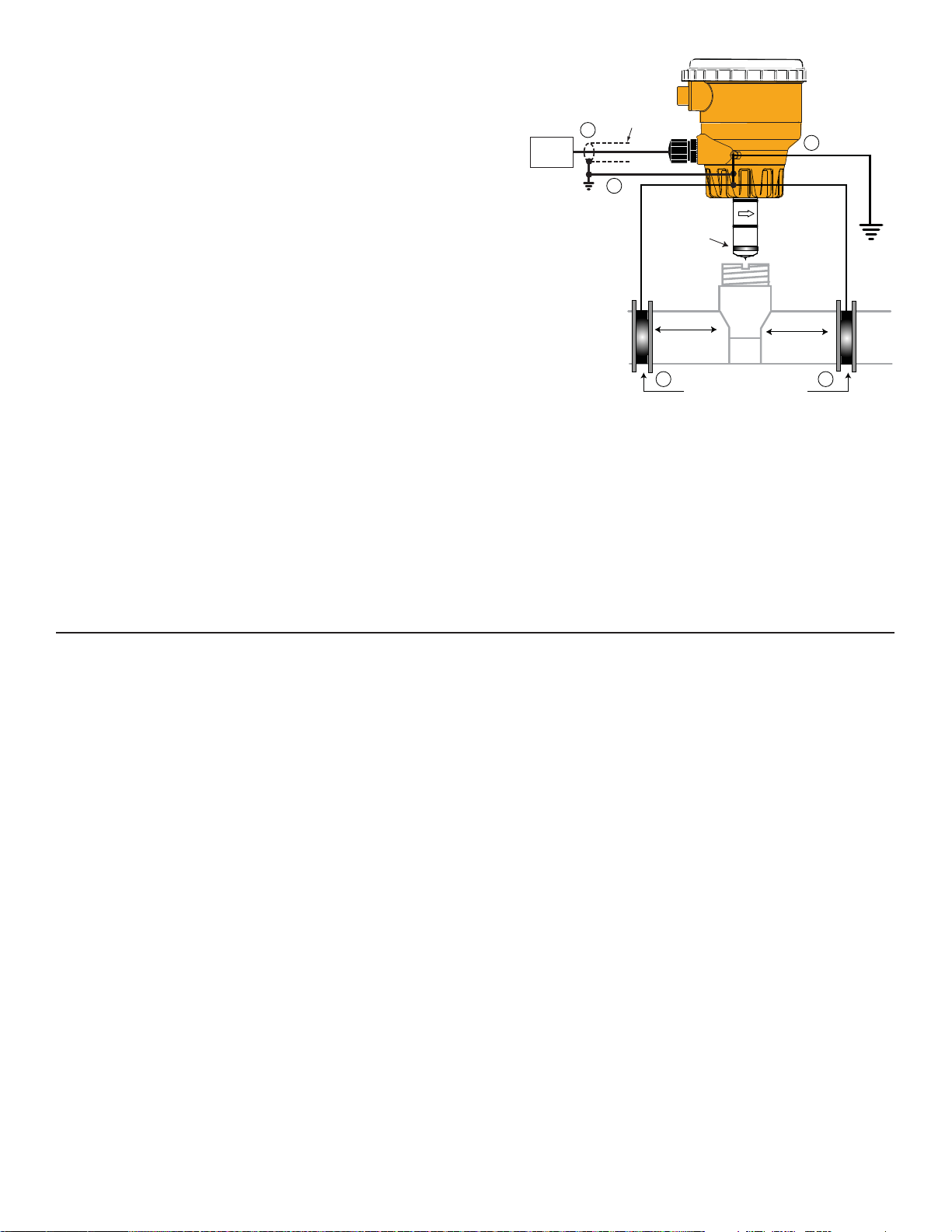
12.0 Technical Information
12.1 Grounding
Do not terminate
shield at Magmeter
Precalibration conditioning: The magmeter may appear to be unstable
immediately after installation. Allow the sensor to sit in a full pipe for 24
hours before beginning calibration and operation.
• Use a cable gland or a liquid tight connector to seal the cable ports
Instrument
3.
1.
4.
from water intrusion.
• Use Tefl on tape or a suitable sealant on cable ports.
• The magmeter must be carefully grounded to eliminate electrical noise
Sensor
Grounding ring
that may interfere with the measurement.
• Grounding requirements will vary with each installation.
• The following recommendations should be applied in sequence until the
interference is eliminated.
The ground terminal on the outside of the yellow housing is connected
4 in. to 50 in.
(10 cm to 1.3 m)
4 in. to 50 in.
(10 cm to 1.3 m)
internally to the grounding ring at the tip of the sensor. Connect a
conductor (14 AWG/2.08 mm2 wire recommended) from this terminal
directly to Earth ground to prevent electrical noise from interfering with
the magmeter signal.
Grounding rings on plastic pipe
(Install between flanges)
or
metal straps on metal pipe
2. 2.
If the interference persists, apply step #2:
Connect grounding rings, metal clamps or grounding electrodes to the pipe immediately upstream and downstream of the
magmeter sensor location. These devices must be in contact with the fl uid.
If the interference persists, apply step #3:
The shield from the output cable must be terminated at the remote instrument ONLY.
This shield must not be connected at both ends!
If the interference persists, apply step #4:
Connect an additional wire (minimum AWG 14/2.08 mm
2
) from the remote instrument ground to the magmeter ground terminal.
13.0 Ordering Information
Order number Description
FMG-3001-PP-D Display Magmeter, freq out, PP sensor, 0.5 to 4 inch pipe
FMG-3001-PVDF-D-HA Display Magmeter, freq out, PVDF/HA sensor, 0.5 to 4 inch pipe
FMG-3101-PP-D Display Magmeter, freq out, PP sensor, 5 to 8 inch pipe
FMG-3101-PVDF-D-HA Display Magmeter, freq out, PVDF/HA sensor, 5 to 8 inch pipe
FMG-3201-PP-D Display Magmeter, freq out, PP/SS sensor, 10 to 12 inch pipe
FMG-3201-PVDF-D-HA Display Magmeter, freq out, PVDF/HA sensor, 10 to 12 inch pipe
FMG-3002-PP-D Display Magmeter, 4 to 20 out, PP sensor, ½ to 4 inch pipe
FMG-3002-PVDF-D-HA Display Magmeter, 4 to 20 out, PVDF/HA sensor, 0.5 to 4 inch pipe
FMG-3102-PP-D Display Magmeter, 4 to 20 out, PP sensor, 5 to 8 inch pipe
FMG-3102-PVDF-D-HA Display Magmeter, 4 to 20 out, PVDF/HA sensor, 5 to 8 inch pipe
FMG-3202-PP-D Display Magmeter, 4 to 20 mA out, PP/SS sensor, 10 to 12 inch pipe
FMG-3202-PVDF-D-HA Display Magmeter, 4 to 20 mA out, PVDF/HA sensor, 10 to 12 inch pipe
Replacement Parts and Accessories
FPP-1220-0021 O-ring, FPM
FPP-1224-0021 O-ring, EPDM
FPP-1228-0021 O-ring, FFPM
FPM-5000-LTCK Liquid Tight Connector Kit
Page 22

12.2 Maintenance
The OMEGAMAG
®
requires very little maintenance. There are no user-serviceable components in the magmeter.
• If the fl uid contains deposits and solids that may coat the electrodes, a regular cleaning regimen is recommended.
• Do not use abrasive materials on the metal electrodes. Clean with soft cloth and mild detergent only.
• Use a cotton swab and mild detergent to remove deposits on the metal electrodes.
12.3 Troubleshooting
Symptom Possible Cause Solution
Magmeter installed too close to upstream
obstruction.
Magmeter located in area exposed to air
bubbles/pockets.
Relocate the magmeter to have straight
uninterrupted pipe upstream of the sensor
for at least 10 x the pipe diameter.
Eliminate air bubbles in the pipe.
Remove the magmeter and reinstall with
Output is erratic and unstable.
Magmeter is installed in pipe backwards.
the fl ow direction arrow on the sensor body
pointed DOWNSTREAM.
Review the grounding of the magmeter
Electrical noise is interfering with the
measurement.
and the pipe. Install adequate Earth
ground to allow the Magmeter to operate
properly.
Output is not 0 when fl ow is stopped.
Electrodes are coated with deposits or
chemical oxide layers.
Electrodes not adequately conditioned in
fl uid.
Carefully clean the electrodes. Refer to
sensor manual for details.
Allow the sensor to sit in full pipe for 24
hours then restart.
Fluid is moving inside the pipe Increase the Low Flow Cutoff. (section 7.0)
No 4-20 mA output. Loop power not connected correctly.
Connect 24 VDC ±10% connected to loop
terminals 1 and 3
4-20 mA current output is incorrect. 4-20 mA is not scaled properly Check and reset in the Setup Menu
Magmeter is wrong model.
Frequency model:
FMG3001 or FMG3101
Incorrect setting in Options Menu. Select Frequency in the Options menu.
No Frequency output.
Wiring is not correct. Check wiring, make corrections.
Frequency input to other manufacturer's
fl ow instrument does not have pull-up
Install 10 kΩ resistor. (section 5.1)
resistor.
No fl ow rate, current output is 22 mA
Blank display, no backlighting, no relay
LEDs, but external equipment using output
signal is still working.
Error Message:
"Error Not Saved"
The fl uid is too clean for Magmeter. Unsuitable application for Magmeter.
Electronic component failure. Return Magmeter to factory.
Magmeter AUX power is not connected.
Connect AUX power (section 5.5)
(9 to 24 VDC, 0.4 A max.)
Main power is below specifi cation Correct the main power defi ciency
Troubleshooting with the RED and BLUE lights
The FMG-3000 uses two colored LEDs to indicate the status of the instrument.
They are located at the top of the magmeter, inside the clear plastic cap.
No Lights: The power is off or the sensor is not connected
Solid Blue (D7): The power is on, the pipe is full, but there is no fl ow in the pipe.
Blinking Blue (D7): Normal operation, blink rate is proportional to the fl ow rate.
Alternating Red-Blue: Empty pipe indication (electrodes are not wet.)
Blinking Red (D6): System errors (Electrical noise interference)
Solid Red (D6): Instrument error (defective electronics component)
JP2
4
3
2
1
D7
D6
Flow Flow
20
Page 23

U
MAD E
IN
SA
WARRANTY/DISCLAIMER
OMEGA ENGINEERING, INC. warrants this unit to be free of defects in materials and workmanship for a period
of 13 months from date of purchase. OMEGA’s WARRANTY adds an additional one (1) month grace period to the
normal one (1) year product warranty to cover handling and shipping time. This ensures that OMEGA’s customers
receive maximum coverage on each product.
If the unit malfunctions, it must be returned to the factory for evaluation. OMEGA’s Customer Service Department
will issue an Authorized Return (AR) number immediately upon phone or written request. Upon examination by
OMEGA, if the unit is found to be defective, it will be repaired or replaced at no charge. OMEGA’s WARRANTY
does not apply to defects resulting from any action of the purchaser, including but not limited to mishandling,
improper interfacing, operation outside of design limits, improper repair, or unauthorized modification. This
WARRANTY is VOID if the unit shows evidence of having been tampered with or shows evidence of having
been damaged as a result of excessive corrosion; or current, heat, moisture or vibration; improper specifi cation;
misapplication; misuse or other operating conditions outside of OMEGA’s control. Components which wear are not
warranted, including but not limited to contact points, fuses, and triacs.
OMEGA is pleased to offer suggestions on the use of its various products. However, OMEGA neither assumes
responsibility for any omissions or errors nor assumes liability for any damages that result from the use of its
products in accordance with information provided by OMEGA, either verbal or written. OMEGA warrants only that
the parts manufactured by it will be as specifi ed and free of defects. OMEGA MAKES NO OTHER WARRANTIES
OR REPRESENTATIONS OF ANY KIND WHATSOEVER, EXPRESS OR IMPLIED, EXCEPT THAT OF TITLE,
AND ALL IMPLIED WARRANTIES INCLUDING ANY WARRANTY OF MERCHANTABILITY AND FITNESS FOR A
PARTICULAR PURPOSE ARE HEREBY DISCLAIMED.
LIMITATION OF LIABILITY: The remedies of purchaser set forth herein are exclusive, and the total liability of
OMEGA with respect to this order, whether based on contract, warranty, negligence, indemnifi cation, strict liability
or otherwise, shall not exceed the purchase price of the component upon which liability is based. In no event shall
OMEGA be liable for consequential, incidental or special damages.
CONDITIONS: Equipment sold by OMEGA is not intended to be used, nor shall it be used: (1) as a “Basic Component”
under 10 CFR 21 (NRC), used in or with any nuclear installation or activity; or (2) in medical applications or used on
humans. Should any Product(s) be used in or with any nuclear installation or activity, medical application, used on
humans, or misused in any way, OMEGA assumes no responsibility as set forth in our basic WARRANTY/DISCLAIMER
language, and, additionally, purchaser will indemnify OMEGA and hold OMEGA harmless from any liability or damage
whatsoever arising out of the use of the Product(s) in such a manner.
RETURN REQUESTS/INQUIRIES
Direct all warranty and repair requests/inquiries to the OMEGA Customer Service Department. BEFORE RETURNING
ANY PRODUCT(S) TO OMEGA, PURCHASER MUST OBTAIN AN AUTHORIZED RETURN (AR) NUMBER FROM
OMEGA’S CUSTOMER SERVICE DEPARTMENT (IN ORDER TO AVOID PROCESSING DELAYS). The assigned AR
number should then be marked on the outside of the return package and on any correspondence.
The purchaser is responsible for shipping charges, freight, insurance and proper packaging to prevent breakage in transit.
FOR WARRANTY RETURNS, please have the following
information available BEFORE contacting OMEGA:
1. Purchase Order number under which the product was
PURCHASED,
2. Model and serial number of the product under
warranty, and
3. Repair instructions and/or specifi c problems relative to
the product.
FOR NON-WARRANTY REPAIRS,
current repair charges. Have the following information
available BEFORE contacting OMEGA:
1. Purchase Order number to cover the COST of the
repair,
2. Model and serial number of the product, and
3. Repair instructions and/or specifi c problems relative to
the product.
consult OMEGA for
OMEGA’s policy is to make running changes, not model changes, whenever an improvement is possible. This affords our customers
the latest in technology and engineering.
OMEGA is a registered trademark of OMEGA ENGINEERING, INC.
© Copyright 2011 OMEGA ENGINEERING, INC. All rights reserved. This document may not be copied, photocopied, reproduced,
translated, or reduced to any electronic medium or machine-readable form, in whole or in part, without the prior written consent of
OMEGA ENGINEERING, INC.
Page 24

Where Do I Find Everything I Need for
Process Measurement and Control?
OMEGA…Of Course!
Shop online at www.omega.com
TEMPERATURE
•
Thermocouple, RTD & Thermistor Probes, Connectors, Panels & Assemblies
•
Wire: Thermocouple, RTD & Thermistor
•
Calibrators & Ice Point References
•
Recorders, Controllers & Process Monitors
•
Infrared Pyrometers
PRESSURE, STRAIN AND FORCE
•
Transducers & Strain Gages
•
Load Cells & Pressure Gages
•
Displacement Transducers
•
Instrumentation & Accessories
FLOW/LEVEL
•
Rotameters, Gas Mass Flowmeters & Flow Computers
•
Air Velocity Indicators
•
Turbine/Paddlewheel Systems
•
Totalizers & Batch Controllers
pH/CONDUCTIVITY
•
pH Electrodes, Testers & Accessories
•
Benchtop/Laboratory Meters
•
Controllers, Calibrators, Simulators & Pumps
•
Industrial pH & Conductivity Equipment
DATA ACQUISITION
•
Data Acquisition & Engineering Software
•
Communications-Based Acquisition Systems
•
Plug-in Cards for Apple, IBM & Compatibles
•
Datalogging Systems
•
Recorders, Printers & Plotters
HEATERS
•
Heating Cable
•
Cartridge & Strip Heaters
•
Immersion & Band Heaters
•
Flexible Heaters
•
Laboratory Heaters
ENVIRONMENTAL
MONITORING AND CONTROL
•
Metering & Control Instrumentation
•
Refractometers
•
Pumps & Tubing
•
Air, Soil & Water Monitors
•
Industrial Water & Wastewater Treatment
•
pH, Conductivity & Dissolved Oxygen Instruments
6-2551.090-1-OM (D-3/12) M-4334/0312
 Loading...