

Page 1
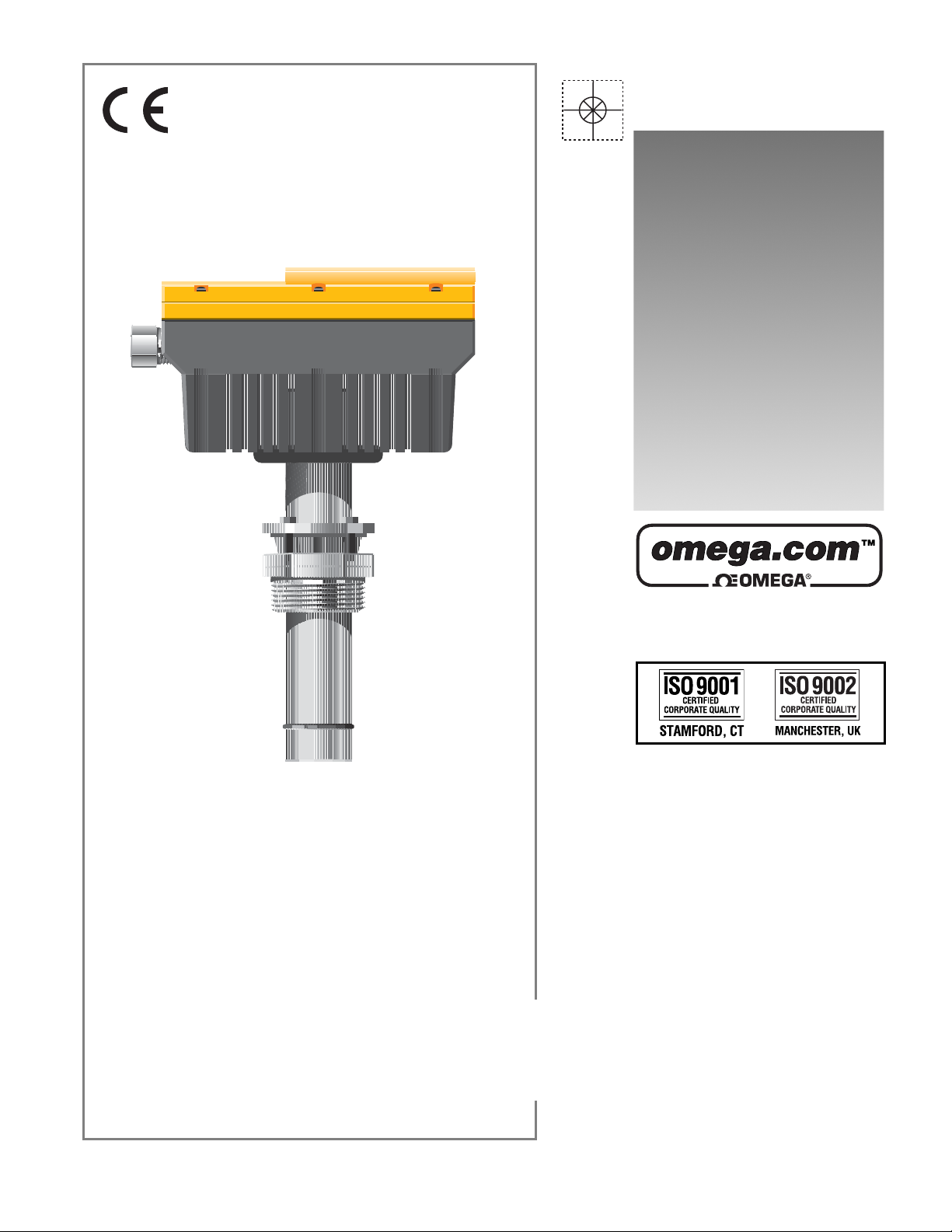
User’s Guide
Shop online at
www.omega.com
e-mail: [email protected]
FMG 2550 Series
Insertion Magmeter
Page 2

OMEGAnet® Online Service Internet e-mail
www.omega.com [email protected]
Servicing North America:
USA: One Omega Drive, P.O. Box 4047
ISO 9001 Certified Stamford CT 06907-0047
TEL: (203) 359-1660 FAX: (203) 359-7700
e-mail: [email protected]
Canada: 976 Bergar
Laval (Quebec) H7L 5A1
TEL: (514) 856-6928 FAX: (514) 856-6886
e-mail: [email protected]
For immediate technical or application assistance:
USA and Canada: Sales Service: 1-800-826-6342 / 1-800-TC-OMEGA
Customer Service: 1-800-622-2378 / 1-800-622-BEST
Engineering Service: 1-800-872-9436 / 1-800-USA-WHEN
TELEX: 996404 EASYLINK: 62968934 CABLE: OMEGA
®
®
®
Mexico: En Español: (001) 203-359-7803 e-mail: [email protected]
FAX: (001) 203-359-7807 [email protected]
Servicing Europe:
Benelux: Postbus 8034, 1180 LA Amstelveen, The Netherlands
TEL: +31 (0)20 3472121 FAX: +31 (0)20 6434643
Toll Free in Benelux: 0800 0993344
e-mail: [email protected]
Czech Republic: Rudé armády 1868, 733 01 Karviná 8
France: 9, rue Denis Papin, 78190 Trappes
TEL: +33 (0)130 621 400 FAX: +33 (0)130 699 120
Toll Free in France: 0800-4-06342
e-mail: [email protected]
Germany/Austria: Daimlerstrasse 26, D-75392 Deckenpfronn, Germany
TEL: +49 (0)7059 9398-0 FAX: +49 (0)7056 9398-29
Toll Free in Germany: 0800 639 7678
e-mail: [email protected]
United Kingdom: One Omega Drive, River Bend Technology Centre
ISO 9002 Certified Northbank, Irlam, Manchester
M44 5EX United Kingdom
TEL: +44 (0)161 777 6611 FAX: +44 (0)161 777 6622
Toll Free in United Kingdom: 0800-488-488
e-mail: [email protected]
It is the policy of OMEGA to comply with all worldwide safety and EMC/EMI regulations that
apply. OMEGA is constantly pursuing certification of its products to the European New Approach
Directives. OMEGA will add the CE mark to every appropriate device upon certification.
The information contained in this document is believed to be correct, but OMEGA Engineering, Inc. accepts
no liability for any errors it contains, and reserves the right to alter specifications without notice.
WARNING: These products are not designed for use in, and should not be used for, patient-connected applications.
Page 3

Unpacking and Inspection
The OMEGA FMG2550 Series Insertion
Magmeter package includes the following items:
•FMG2550 Series Sensor
•M-2974 Instruction Manual
•FMG255-T installation tool (optional)
Warranty record
For your protection, record the purchase
information for future reference. The serial number
decal is located on the sensor, and also inside the
wiring access plate.
Model: OMEGA FMG2550 Series
Insertion Magmeter
Purchase date:________________________
Serial number:________________________
Purchased from:_______________________
Purchase order number:________________
The technical information
given in this manual is for
general information only.
It implies no warranty of
any kind.
Page 4
Important Safety Information!
CAUTION: Do not remove from pressurized lines!
Do not remove safety ring from sensor. Unit may
become a dangerous projectile if safety devices
are disabled.
Do not open wiring access plate in humid
environment. Moisture in terminal area may cause
instrument failure.
In EDIT mode, all the output functions of the
OMEGA FMG2550 Series Insertion Magmeter
are still active, so the control process is uninterrupted.
The OMEGA FMG2550 Series Insertion
Magmeter weighs 11 lbs. Care must be taken to
properly support the unit with straps and/or
bracing when necessary.
Page 5

Chapter 1
Introduction
1.1 Description
Chapter 2
Installation and wiring
2.1 Sensor location
2.2 Preparing the pipe
2.3 Sensor installation with tool
2.4 Sensor installation without tool
2.5 Wiring
2.6 Grounding requirements
2.7 Installation tips
Chapter 3
Operation
3.1 Control panel description
3.2 Main menu
3.2.1 Access code
3.3 Calibrate functions
3.3.1 Unit
3.3.2 Interior diameter
3.3.3 Current output
3.4 Performance functions
3.4.1 Sensitivity
3.4.2 Response time
3.4.3 Viscosity
3.4.4 AC noise filter
3.4.5 Calibration "B"
3.5 Display options
3.5.1 Operational outputs
3.5.2 Diagnostic displays
3.6 Frequency output
3.6.1 Product compatibility
3.7 Calibration data
3.8 Custom K-factor calculation
3.9 Spare parts list
Specifications
Page
1
1
2
2
2
3
4
5
6
7
8
8
9
10
10
11
12
13
14
14
15
16
16
17
18
18
19
20
20
20
23
24
25
Table of Contents
Page 6
This manual contains descriptions, specifications,
and instructions for the installation and operation of
the OMEGA FMG2550 Series Insertion
Magmeter. Should you require further assistance,
please contact OMEGA.
1.1 Description
The latest in bipolar pulsed DC technology and the
best features of an insertion sensor are packed into
the OMEGA FMG2550 Series Insertion
Magmeter. Simple installation, easy maintenance,
and state-of-the-art microprocessor technology
make the FMG2550 Series the best alternative to
traditional full-line magmeters.
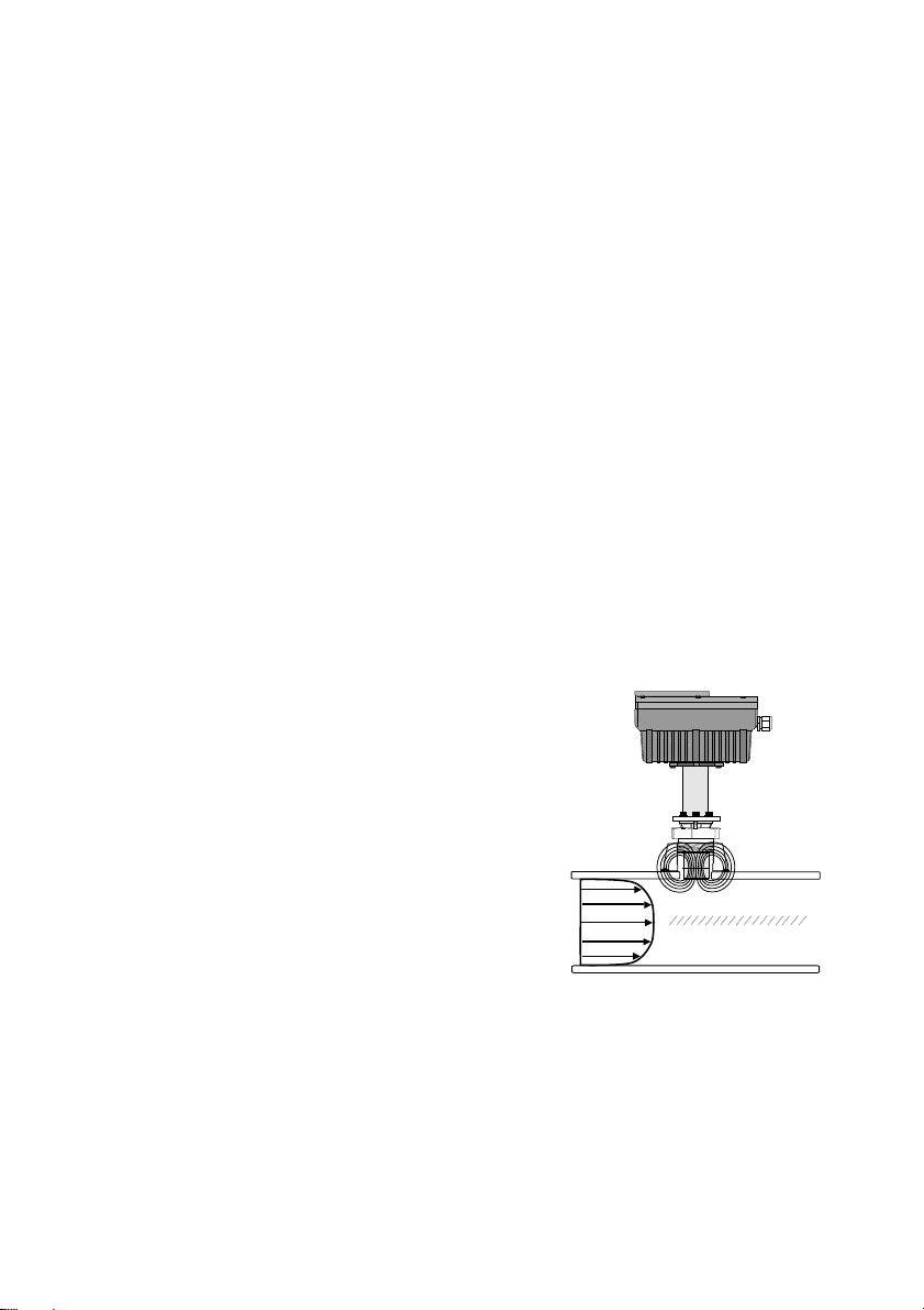
The FMG2550 is based on the Faraday principle,
and provides current frequency output signals
proportional to the flow rate. The system
incorporates automatic temperature compensation,
resulting in outputs that are accurate within ±2% of
actual flow rate.
Chapter 1
Introduction
The bipolar electronic design and the 10000 MΩ
input impedance reduce galvanic formation on the
electrodes and minimize coating problems.
The isolated current output provides an universal
signal to recorders, valves, process control and
data acquisition devices.
The open collector frequency output is compatible
with all powered flow controllers such as the
OMEGA FPM-9010A Flow Controller.
See Section 3.9 for an exploded view of the
FMG2550 Series Magmeter.
Fully Developed
Flow Profile
Faraday’s Principle: Movement of a conductive fluid
through a magnetic field
generates a perpendicular
electromotive force proportional to its velocity.
1
Page 7
Chapter 2
Installation
and wiring
Inlet
Flange
10 x id 5 x id
Inlet
Reducer
15 x id 5 x id
Inlet
90° elbow
Outlet
Outlet
Outlet
The linearity and accuracy of the FMG2550
Series depends on precise alignment and insertion
depth of the sensor in the pipe and accurate
measurement of the pipe dimensions. The
installation tool (FMG255-T) is recommended for
best results.
2.1 Sensor location
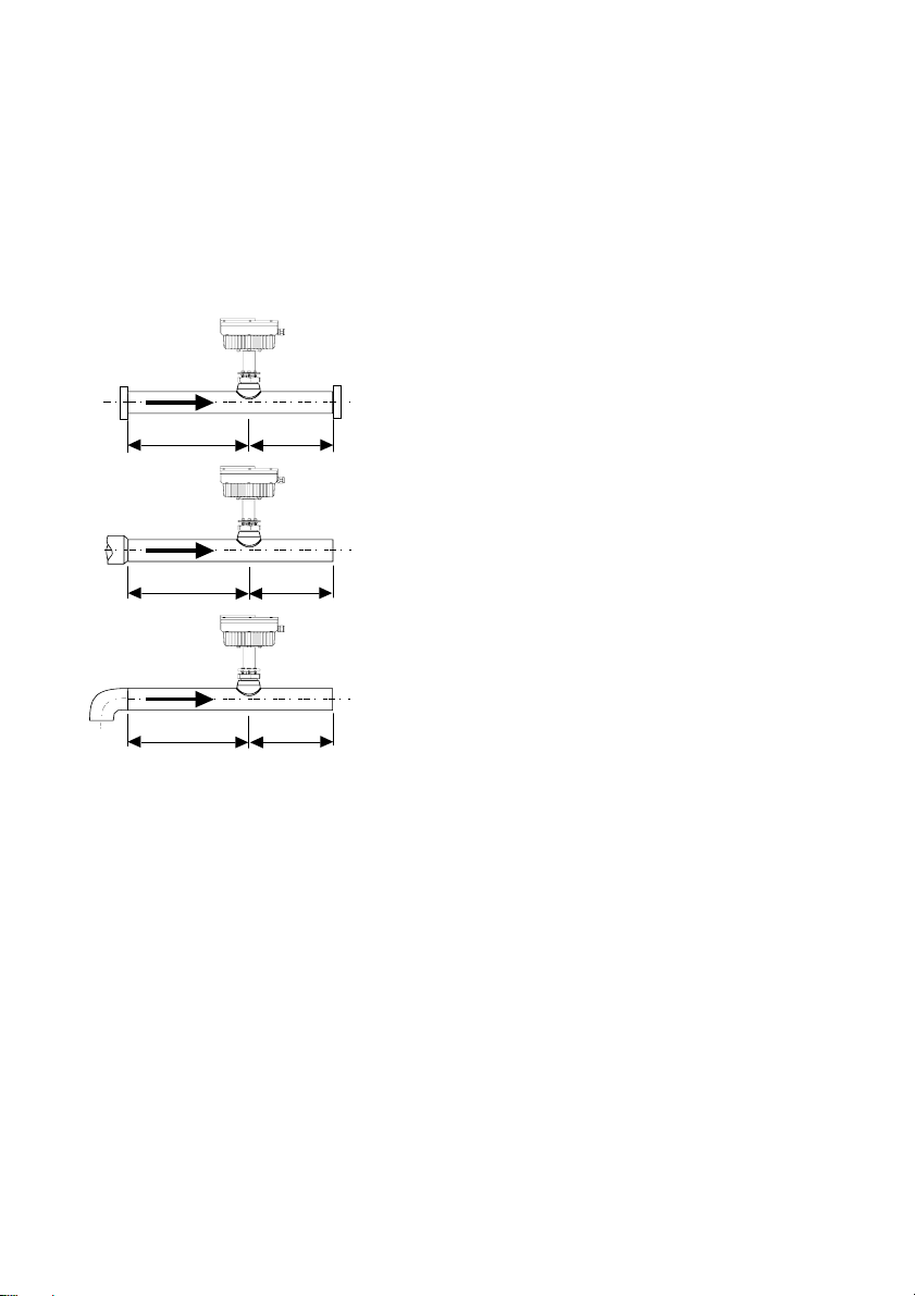
Select a location for the sensor where the flow
profile is fully developed and not affected by any
disturbances. A minimum of 10 pipe diameters of
straight run upstream and 5 diameters downstream
is recommended. Some situations may require 20
pipe diameters or more upstream to insure a fully
developed turbulent flow profile.
The 2550 is sensitive to air bubbles at the
electrodes. If there is any question that the pipe is
absolutely full, mount the sensor at a 45 to 135°
angle. The magmeter requires a clearance of
approximately 16 in./400 mm for removal.
20 x id 5 x id
Measure and record the
interior diameter of the pipe.
This value will be required to
calibrate the FMG2550
Series.
Interior diameter:
______________________________
2
2.2 Preparing the pipe
1. Cut a 2.125 in. ±1/16 in. (54 mm ±1.6 mm)
opening in the pipe. Carefully debur the hole for
best results.
2. Install a standard 2 in. saddle or weld-on fitting
on the pipe. Welded fittings should be installed
by qualified personnel. The threads must be
perpendicular to the pipe within 1° for proper
performance.
Page 8
2.3 Sensor Installation with tool
FLOW
PIPE I.D.
2A
Process Pipe
Cutaway Side View
2B
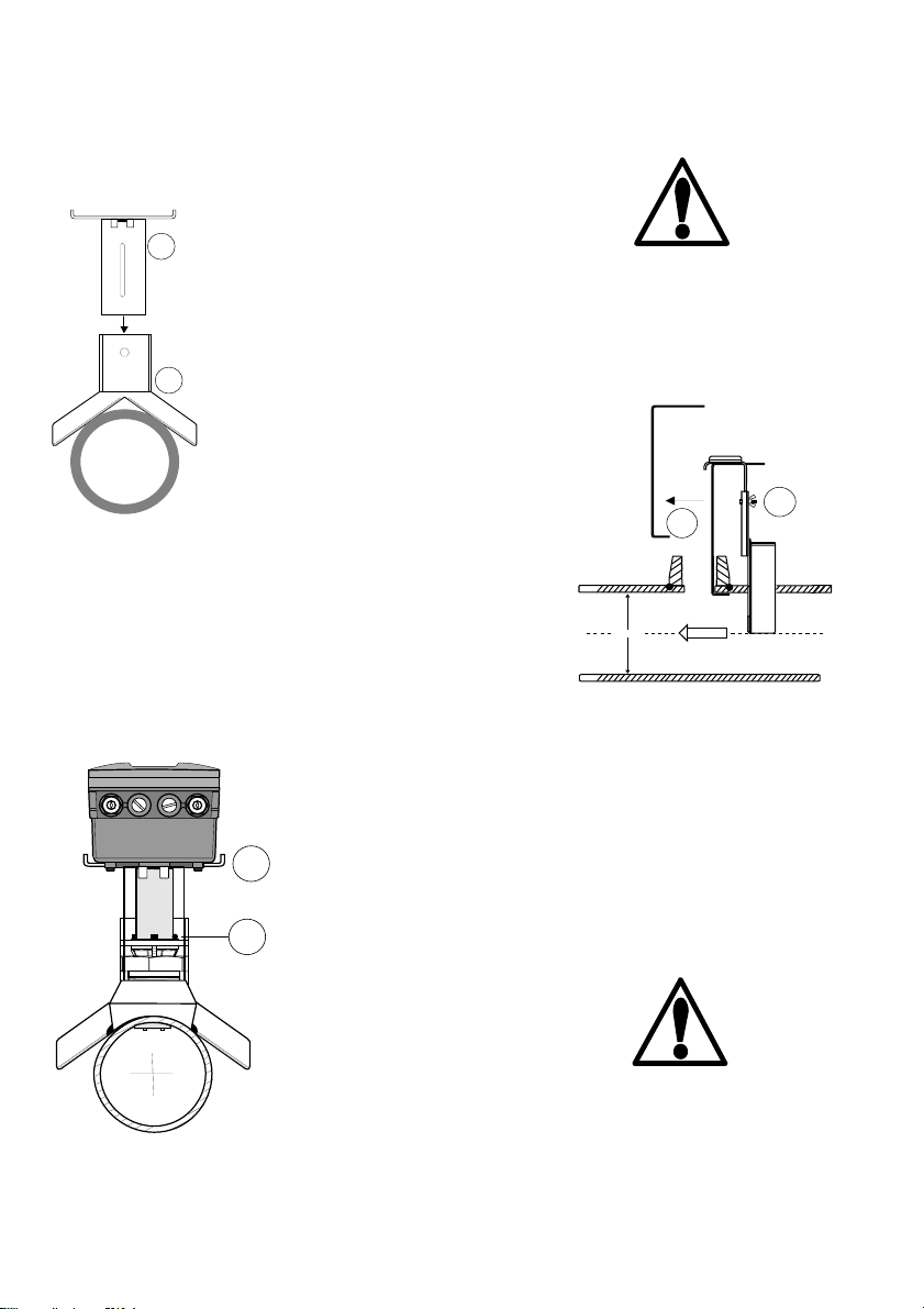
The installation tool (FMG255-T) simplifies
installation and insures proper insertion depth for
maximum accuracy.
1B
1. Set installation tool angle
plate (1A) on pipe next to fitting.
Insert adjusting slide (1B) into
top of angle plate.
1A
Installation Tool
Front View
2. Place height gauge (2A) short end inside pipe
and pull up against inside diameter of pipe. Insert
height gauge long end into slot in adjusting slide.
Tighten wing nut (2B) to hold adjusting slide in
place against angle plate. Remove height gauge
from pipe.
3. Loosen the three bolts
at top of the magmeter
adjustment nut (3A).
Wrap the adjustment nut
threads with three full
3B
wraps of sealing tape and
insert sensor into fitting until
base of the electronics
3A
enclosure is resting on top
of adjusting slide (3B).
Be sure cable ports are
pointing downstream.
Thread adjustment nut
Process Pipe
Cutaway Front View
securely into pipe. Tighten
all three bolts to secure
adjustment nut.
Important Safety
Information!
Do not remove safety
ring or adjustment nut
from sensor.
The FMG2550 Series
Magmeter weighs 11 lbs.
Care must be taken to
properly support the unit with
straps and/or bracing when
necessary.
3
Page 9
Important Safety
Information!
2.4 Sensor Installation without tool
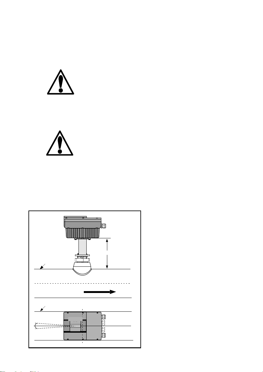
It is recommended that the installation tool always
be used when installing the FMG2550 Series
Insertion Magmeter. If the installation tool is not
available, follow the instructions below. Pay
careful attention to the insertion depth of the sensor
in the pipe and the alignment of the electrodes
relative to the pipe.
Do not remove safety
ring or adjustment nut
from sensor.
The FMG2550 Series
Magmeter weighs 11 lbs.
Care must be taken to
properly support the unit with
straps and/or bracing when
necessary.
Process Pipe
1. Loosen three bolts at top of 2550 adjustment
nut. Wrap adjustment nut threads with 3 full
wraps of Sealing tape and insert 2550 sensor
into fitting. Be sure cable ports are pointing
downstream. Thread adjustment nut securely
into pipe.
2. Adjust meter height so tip of sensor is 0.20
inches below the inside diameter of pipe.
Calculate the "H" dimension:
H = sensor length - 0.2 in - wall =
8.1025 in. - 0.2 in -wall
H = 7.9025 - wall
(H = 200 mm - wall thickness)
3. Align the magmeter parallel with
the pipe ±1°. Retighten the
three 3/16 inch bolts to secure
"H"
Pipe Side View
the sensor in the pipe.
Direction of Flow
Process Pipe
Align Magmeter
with pipe ±1 °
4
FLOW
Pipe Top View
Page 10
2.5 Wiring
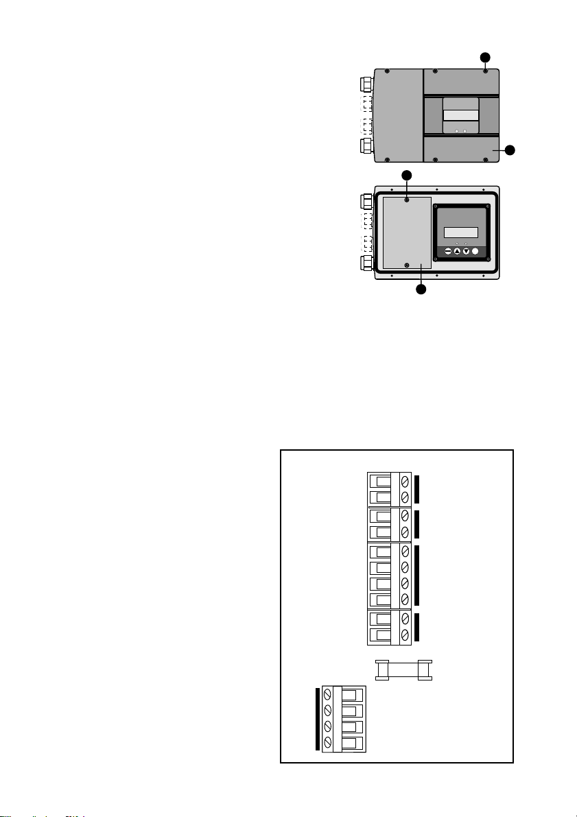
To access the wiring terminals in the FMG2550
Series Magmeter, loosen six captive outer cover
screws (1), lift off outer cover (2), then loosen two
captive screws (3) and remove access plate (4).
A wiring diagram is located on the inside of the
access plate. Five terminal strips are available.
TS 3 Analog output
4 to 20 mA or 0 to 20 mA output
terminal 1 positive (R+)
terminal 2 negative (R-)
18 to 22 AWG wire recommended.
TS4 Serial communication - future expansion
not available in this model.
TS 2 Frequency output
terminal 1 black 5 to 12 VDC in
terminal 2 red open collector pulse out
terminal 3/4 shield cable shield/gnd
see sec 3.4 for detailed information.
18 to 22 AWG wire recommended.
TS 1 Power input
terminal 1 negative
terminal 2 positive
14 to 20 AWG wire recommended.
Recommended power supply:
OMEGA Part #: U24Y101
TS5 Case
chassis ground terminals; see sec 2.6.
Case
Case
3
4
All wiring is installed through
the watertight ports in the
meter. Wrap threads with
sealing
tape before threading
into sockets.
4-20 TS3
4-20 TS3
TS4
TS4
RS485
RS485
RED
RED
SHLD
SHLD
SHLD
SHLD
SHLD
SHLD
24V
24V
TS5
TS5
4
4
3
3
2
2
1
1
TS2
TS2
BLK
BLK
R+
R+
R-
R-
1
1
Analog Output
Analog Output
2
2
(internally powered)
(internally powered)
1
1
B
B
A
A
-
-
+
+
TS1
TS1
Serial
Serial
2
2
Communication
Communication
1
1
2
2
Frequency
Frequency
Frequency
Frequency
3
3
Output
Output
Output
Output
4
4
1
1
Power Input
Power Input
2
2
Fuse
Fuse
Wiring
Diagram
RUN
EDIT
3/4 A
3/4 A
Slo-Blo
Slo-Blo
1
FLOW
2
FLOW
ENTER
5
Page 11
110
V
AC
2.6 Grounding requirements
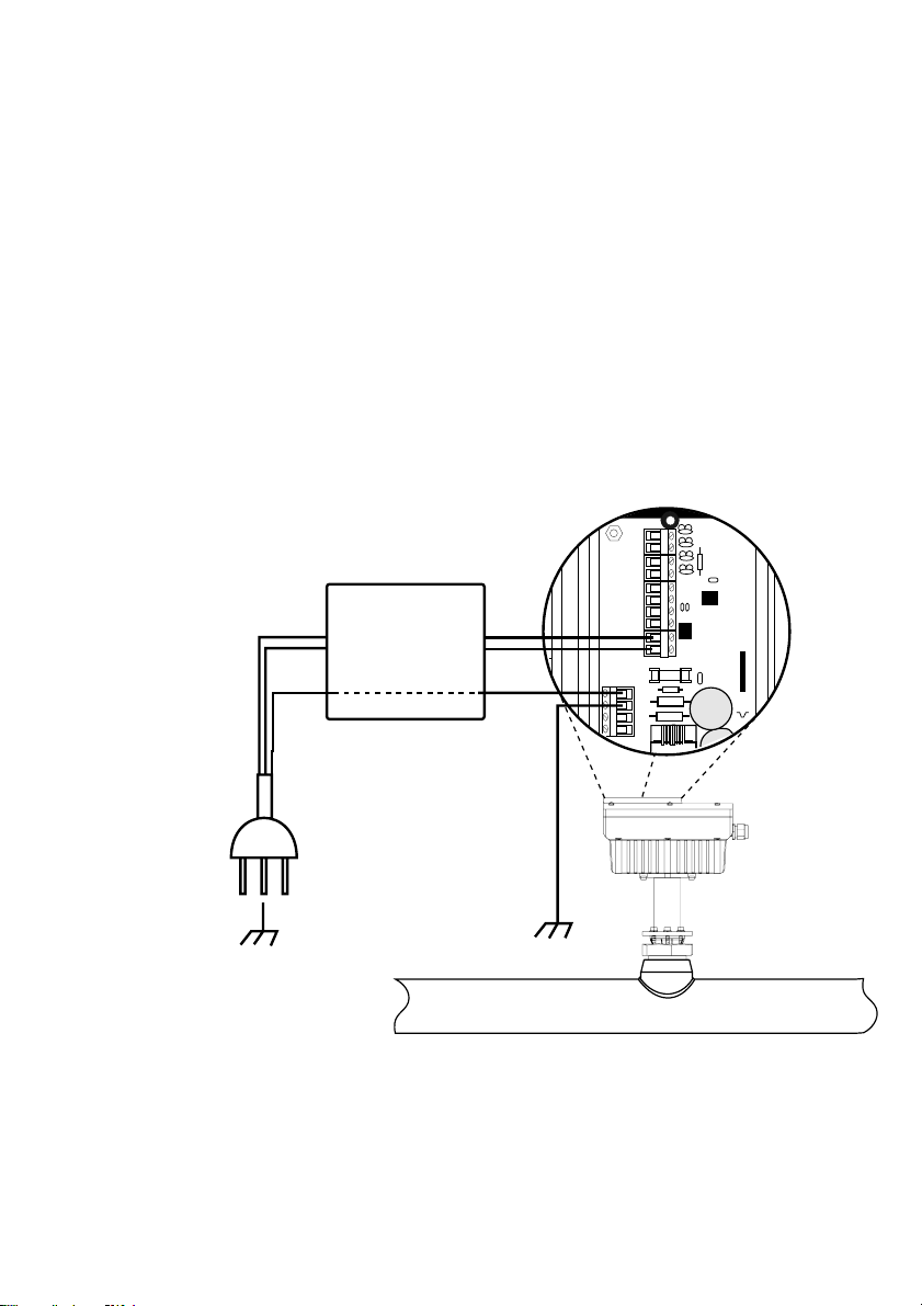
The FMG2550 Series, like all magnetic flow
sensors, is sensitive to electrical noise which is
present in most piping systems. The grounding
procedure illustrated below is necessary in all
installations to insure proper performance.
Connect a local earth ground to the TS5 terminal
strip as illustrated (EG1). If the cable from power
source to the magmeter is less than 200 ft./61m,
EG2 is an acceptable alternative. Using both
EG1 and EG2 is always the best system.
AC+
ACN
Earth Ground #2 (EG2)
24 VDC 1A
Power Supply
-
+
RS485
TS5
4-20 TS3
SHLD
SHLD
24V
4
3
2
1
1
R+
2
R-
TS4
1
B
2
A
TS2
1
BLK
2
RED
3
4
1
-
2
+
TS1
FMG2550 Series
Earth Ground #1
Local
(EG1)
Process Pipe
6
Page 12
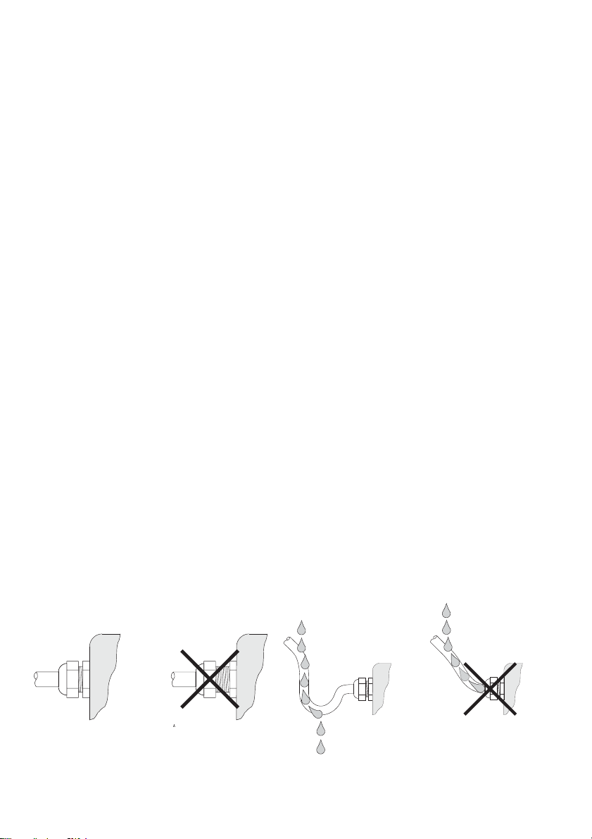
2.7 Installation tips
With moisture
drip loop
Without moisture
drip loop
1. Make sure the Filter function is set to the proper
value for your AC power source (50 or 60 Hz).
(See sec 3.4.4)
2. Allow the magmeter to operate for a period
before attempting to calibrate the unit. The
electronics require a "settling" period during which
the electrode may generate unstable signals.
Thirty minutes to one hour is sufficient.
3. In plastic piping systems, the fluid carries
significant levels of static electricity that must be
grounded for best magmeter performance.
Since plastic pipe is not grounded as metal pipes
are, extra steps must be taken. Identify the places
where the fluid is in electrical contact with external
metal structures or grounds. Connect these points
to TS5 wherever practical.
4. Connect the 24 VDC power and the analog
output signal cables through separate cable ports.
If the frequency output is being used, install a
watertight cable connector in one of the unused
ports. Do not run two cables through one port.
Doing so will defeat the watertight integrity of the
port. (See sec 3.9, spare parts list)
Cable gland
tightened
Cable gland
not tightened
careful cable routing and sealed ports can help prevent water intrusion.
7
Page 13
Chapter 3
Operation
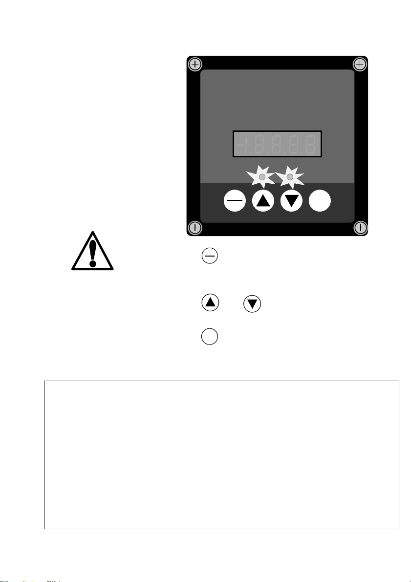
4 digit liquid crystal display:
"-- -- -- -- --" indicates
reverse flow. All signal
outputs are disabled.
3.1 Control panel description
FLOW
• The
RUN
EDIT
RUN
key switches the display from normal
EDIT
ENTER
operation (RUN) to EDIT, where the calibration
During EDIT mode, all the
output functions of the
magmeter are still active, so
the control process is
uninterrupted.
parameters can be modified.
• The and keys scroll through the menu
selections and edit options.
ENTER
• The
key serves two functions:
1. Selects a particular item from main menu.
2. Stores a new value in calibration functions.
Two lamps on the front panel provide a visual indication of system status:
Indication steady green lamp: normal operation
Indication flashing green lamp: noise level exceeds acceptable
range; all outputs frozen at last value
for 10 seconds.
Indication flashing red lamp: when intermittent flow is detected
8
Page 14
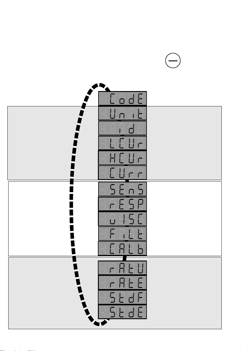
3.2 Main menu
The menu is constructed in a loop, so you can
move forward and backward to select an item.
After any item is edited, the display will return to
the main menu in the same location where it left
off.
RUN
EDIT
Press the run/edit key
to enter the main menu.
access code
Calibrate functions
Performance functions
Display functions
engineering units
pipe id
low current
High current
Current span
sensitivity
response time
viscosity
filter
custom calibration
user calibration
displayed
electronic calibration
displayed
standard flow
deviation displayed
standard electrical
deviation displayed
9
Page 15
RUN
EDIT
THIS BASIC OPERATING PROCEDURE REPEATS THROUGHOUT THE FMG2550 SERIES PROGRAM:
1. PRESS
2. P
3. P
RUN
TO ENTER EDIT MENU.
EDIT
RESS / TO MOVE TO A SPECIFIC MENU ITEM.
ENTER
RESS
KEY TO SELECT THE ITEM FOR EDITING.
RESS / /
4. P
5. P
6. P
7. PRESS
ENTER
RESS
RESS / TO SELECT ANOTHER MENU ITEM, OR
TO STORE THE NEW VALUE/SELECTION.
RUN
TO RETURN TO NORMAL OPERATION.
EDIT
ENTER
TO EDIT THE VALUE/SELECTION.
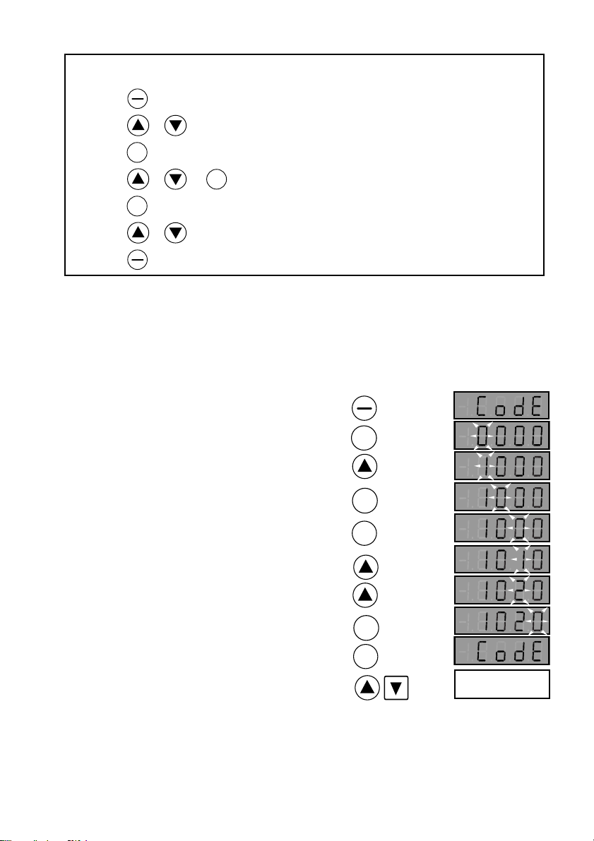
3.2.1 Access code
Without entering the code,
the menu settings can be
viewed, but not edited.
Run/edit key displays first item
in main edit menu.
Enter selects item for editing.
Up arrow advances flashing
digit.
Enter key stores the change
and advances flashing digit.
Up arrow advances flashing
digit.
The main menu begins with a preprogrammed
access code of "1020" which allows editing of
any menu setting.
Step: Press: To display:
1.
2.
3.
4.
5.
6.
7.
ENTER
ENTER
ENTER
Final Enter key returns display
to main edit menu.
10
8.
9.
10.
ENTER
ENTER
Any Function
Any Function
3.3 Calibrate functions
The next five main menu functions are used to input
your specific application data. To edit menu
items, enter code first. (See sec. 3.2.1 above)
Page 16
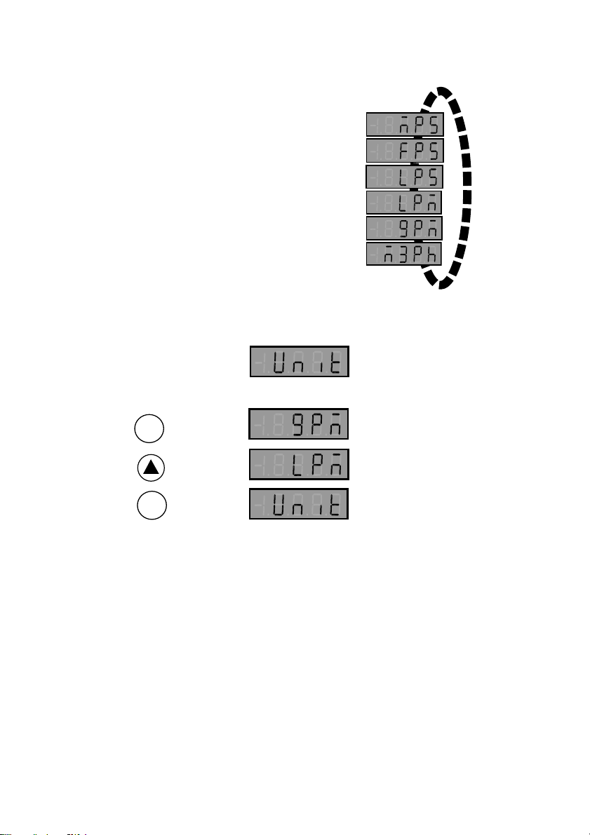
3.3.1 Unit
Six engineering unit options are available in the
unit menu. Select one for your flow rate display.
m/s Meters per second
ft/s Feet per second
l/s Liters per second
l/min Liters per minute
GPM U.S. Gallons per minute
3
m
/h Cubic meters per hour
To change the engineering unit selection, first enter
the access code (section 3.2.1) then press the
down arrow until the display shows:
Step: Press: To display:
1.
ENTER
Example illustrates changing
engineering units from
gallons per minute to
liters per minute.
The factory default setting
for Units is GPM
2.
3.
ENTER
Arrow keys advance main menu function;
run/edit key returns to normal operation.
UP arrow key changes setting
.
ENTER key selects new setting
and returns display to main
menu.
11
Page 17
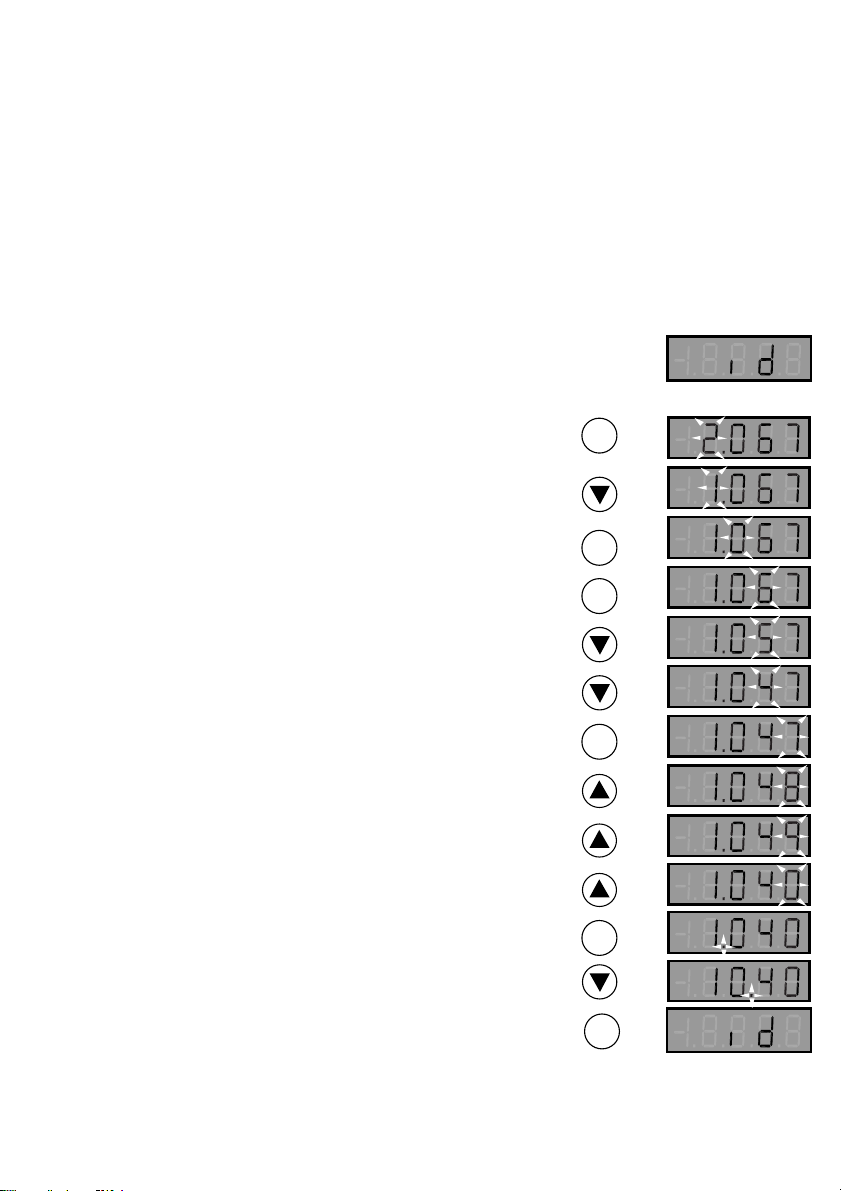
3.3.2 Interior diameter
You must enter the precise interior diameter of your
pipe as measured during the installation process.
Entry is made in inches when the dimension
entered is less than 40, and automatically switches
to millimeters when the dimension entered is
greater than 40.
The example illustrates setting
id to 10.40 in.
The factory default setting
for id is 2.067 in.
Down arrow key
changes flashing digit.
ENTER key stores new setting
and advances flashing digit.
Down arrow key
changes flashing digit.
Up arrow key changes
flashing digit.
To change the id selection, enter the access code
(section 3.2.1) then press the down arrow until the
display shows:
Step: Press: To display:
1.
ENTER
2.
3.
4.
ENTER
ENTER
5.
6.
7.
ENTER
8.
9.
The decimal point location
is selected after the last
flashing digit is set.
Down arrow key moves
decimal to right.
ENTER key stores final setting
and returns to main menu.
12
10.
11.
ENTER
12.
13.
ENTER
Arrow keys advance main menu function;
run/edit key returns to normal operation.
Page 18
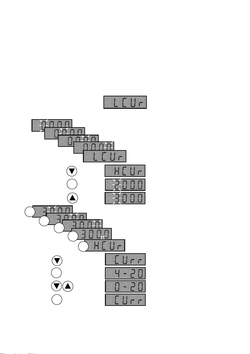
3.3.3 Current output
The current output of the FMG2550 series is set
via three settings. Low current specifies the flow
rate represented by the minimum current signal
(4 or 0 mA). High current is the flow rate represented by the maximum current (20 mA), and
current selects a 4 to 20 or a 0 to 20 mA span.
To change the current selections, first enter the
access code (section 3.2.1) then press the down
arrow until the display shows:
Step: Press: To display:
1.
2.
3.
4.
5.
6.
Example illustrates setting
current output for
0 to 300 GPM = 4 - 20 mA.
The factory default value for
current is :
0 to 200 GPM = 4 - 20 mA.
Down arrow advances to
next menu item.
7.
ENTER
8.
ENTER
9.
ENTER
10.
11.
ENTER
12.
ENTER
13.
ENTER
14.
15.
ENTER
16.
17.
ENTER
Arrow keys advance main menu function;
run/edit key returns to normal operation.
Up arrow changes flashing
digit.
Press enter 5 times to store the
new setting and return to main
menu.
Down arrow advances to
next menu item.
Arrow keys will toggle setting.
Enter key stores final setting
and returns to main menu.
13
Page 19
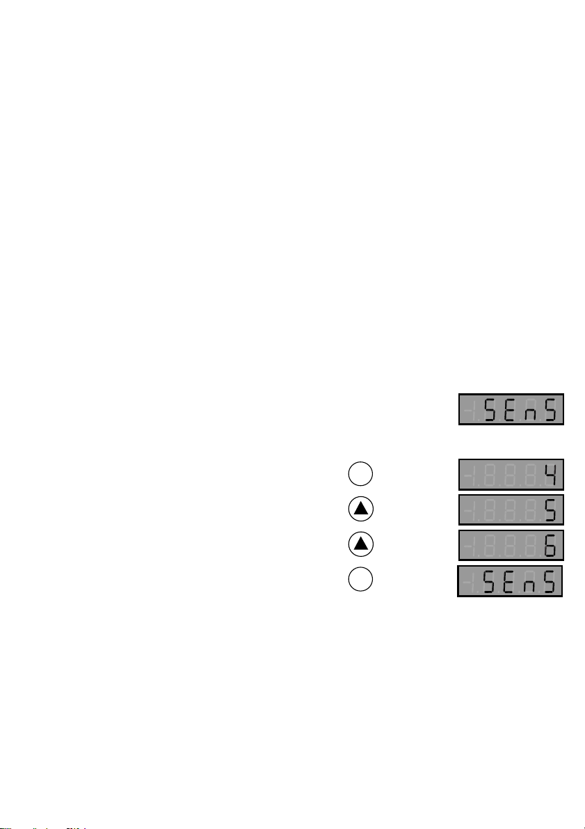
Example illustrates changing
sensitivity setting to 6.
The factory default setting
for sensitivity is 4.
3.4 Performance functions
The next five main menu functions help to tailor the
magmeter signals to your specific environment.
3.4.1 Sensitivity
The sensitivity function limits the amount of reference level noise detected by the magmeter input
circuit. Use the StdE display (sec 3.5.2) to
evaluate the amount of reference noise in your
system. If StdE is greater than 0.05, decreasing
the sensitivity value may stabilize flow readings.
The range selections are from 1 to 10, with 1
representing the most sensitive and 10 the least
sensitive.
To change the sensitivity setting, first enter the
access code (section 3.2.1) then press the down
arrow until the display shows:
Step: Press: To display:
1.
ENTER
Up arrow changes the setting.
The enter key stores the new
setting and returns the display
to the main menu.
14
2.
3.
4.
ENTER
Arrow keys advance to another menu function;
run/edit key returns to normal operation.
Page 20
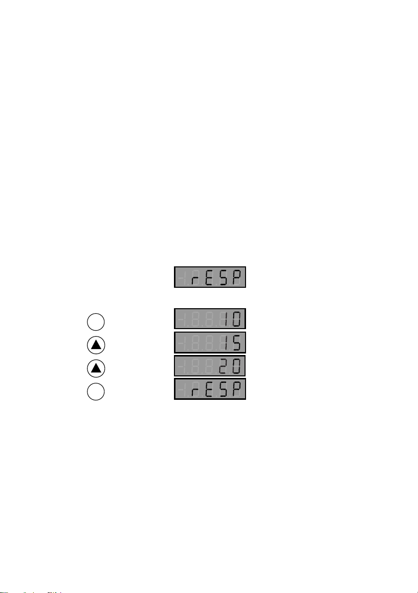
3.4.2 Response time
The response time function varies the rate at which
the output functions adjust to changes in the input
signal. For example, if the response time is set at
10 seconds, the current output will take ten
seconds to reflect 95% of any change in flow
signal input .
Use the response time to reduce the effects of
turbulence and steady/periodic noise in the flow.
The standard flow deviation display (sec. 3.5.2)
will help evaluate the need for increased response
time. The options available are Instantaneous, 5,
10, 15, 20, 30, 40, 60, or 80 seconds.
To change the response time setting, first enter the
access code (section 3.2.1) then press the down
arrow until the display shows:
Step: Press: To display:
1.
ENTER
Example illustrates setting
response at 20 seconds.
The factory default setting
for response is 10 seconds.
2.
3.
4.
ENTER
Arrow keys advance to another menu function;
run/edit key returns to normal operation.
Up arrow changes the
setting.
The enter key stores the new
setting and returns the display
to the main menu.
Page 21
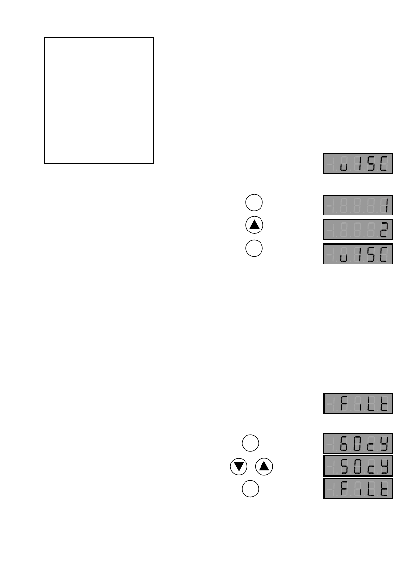
Viscosity ranges
1 = 1 cp
water
2 = 2 cp
3 = 4 cp
4 = 8 cp
5 = N/A- future expansion
The factory default setting
for viscosity is 1.
Press the up arrow to change
the setting to 2.
The enter key stores the new
setting and returns to the main
menu.
3.4.3 Viscosity
Viscosity changes affect the flow profile in the
pipe, and can compromise the accuracy of the
magmeter. This function allows you to compensate
for viscosity. Select a viscosity setting from 1 to 4.
1 represents water, and 2 through 4 represent
increasingly viscous fluids. To change the viscosity
setting, first enter the access code (section 3.2.1)
then press the down arrow until the display shows:
Step: Press: To display:
1.
2.
3.
ENTER
11
ENTER
Arrow keys advance main menu function;
run/edit key returns to normal operation.
3.4.4 AC noise filter
Select 50 Hz or 60 Hz rejection filter according to
the AC power standard in your area.
The factory default setting
for AC filter is 60 cycles.
Press the up or down arrow
to change the setting.
The enter key stores the new
setting and returns to the main
menu.
16
To change the filter setting, first enter the access
code (section 3.2.1) then press the down arrow
until the display shows:
Step: Press: To display:
1.
ENTER
2.
3.
ENTER
Arrow keys advance main menu function;
run/edit key returns to normal operation.
Page 22
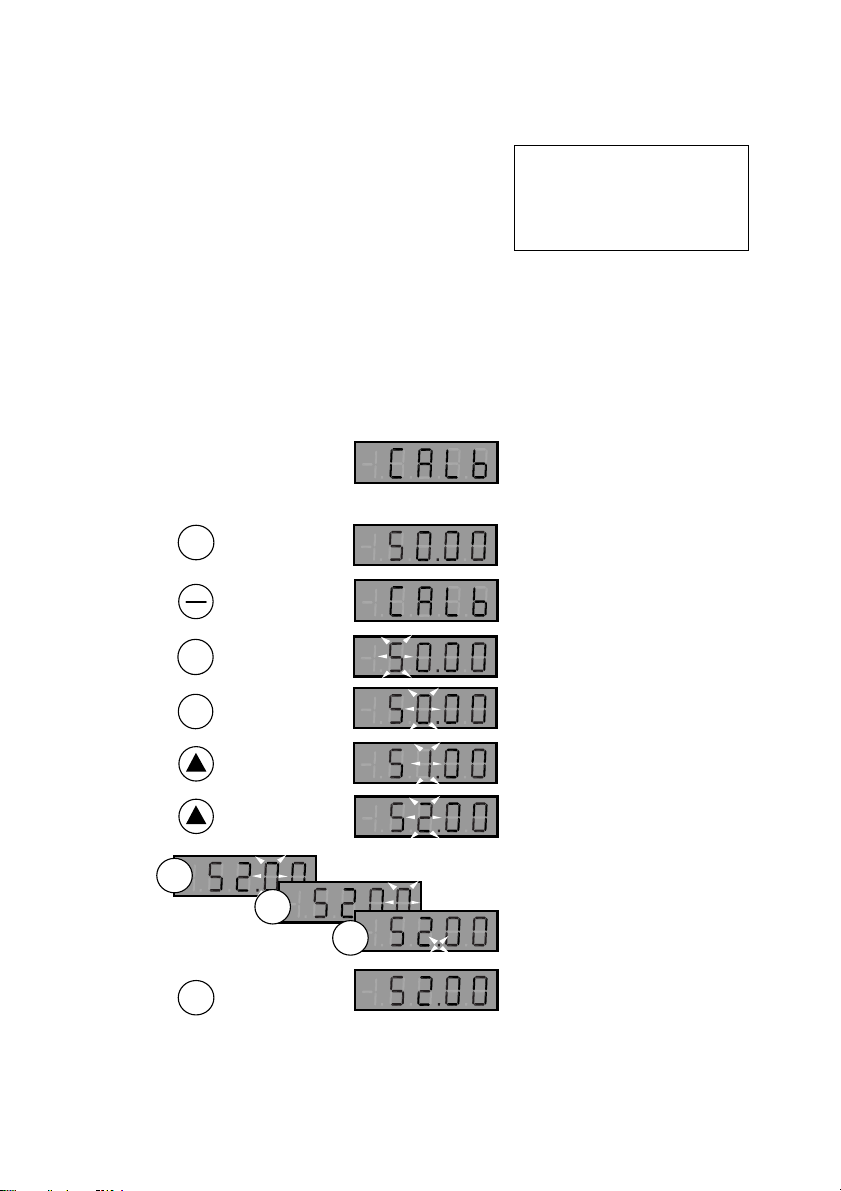
3.4.5 Calibration "B"
The CalB function allows you to compare the
magmeter calibration to your own volumetric or
alternate flow measurement system. The magmeter
stores this flow rate under the display function RatU
(sec. 3.5.1).
The calibration based on the pipe data is still
stored in the memory, and can be recalled by
selecting the display function RatE (sec 3.5.1).
To use CalB, first enter the access code (section
3.2.1) then use the arrow keys until the display
shows:
Calculate the flow rate by
measuring the volume output
for a fixed time period.
volume
÷
time = flow rate
Step: Press: To display:
1.
2.
3.
4.
ENTER
RUN
EDIT
ENTER
ENTER
5.
6.
ENTER
7.
ENTER
8.
ENTER
9.
10.
ENTER
Recall the original calibration by selecting RatE
(See section 3.5.1).
This is current display selection
RatE (see sec 3.5.1)
Now the display has a
flashing digit.
Use the ENTER, UP and
DOWN arrow keys to set the
new flow rate.
When completed, the new
calibration is stored as RatU.
(sec 3.5.1)
Press the ENTER key to
display RatU value.
17
Page 23
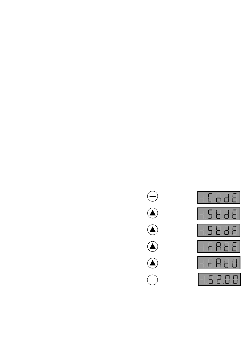
RatE is the factory default
setting.
Example illustrates changing
display setting to StdE.
3.5 Display options
The last four main menu functions change the
displayed information. The first two also change
the output values.
3.5.1 Operational outputs
The "Rate Electronic" and "Rate User" functions
change both the display and the output values in
the magmeter.
• RatE selects the standard calibration value
based on entered pipe id as the basis for all
outputs.
• RatU selects the "Cal B" value as the basis for
all outputs.
Code entry is not necessary to change the display
setting.
Step: Press: To display:
1.
RUN
EDIT
Use the up arrow to move
quickly to the display options.
The display and all outputs
adjust to the new selection
when the enter key is pressed.
18
2.
3.
4.
5.
6.
ENTER
Page 24
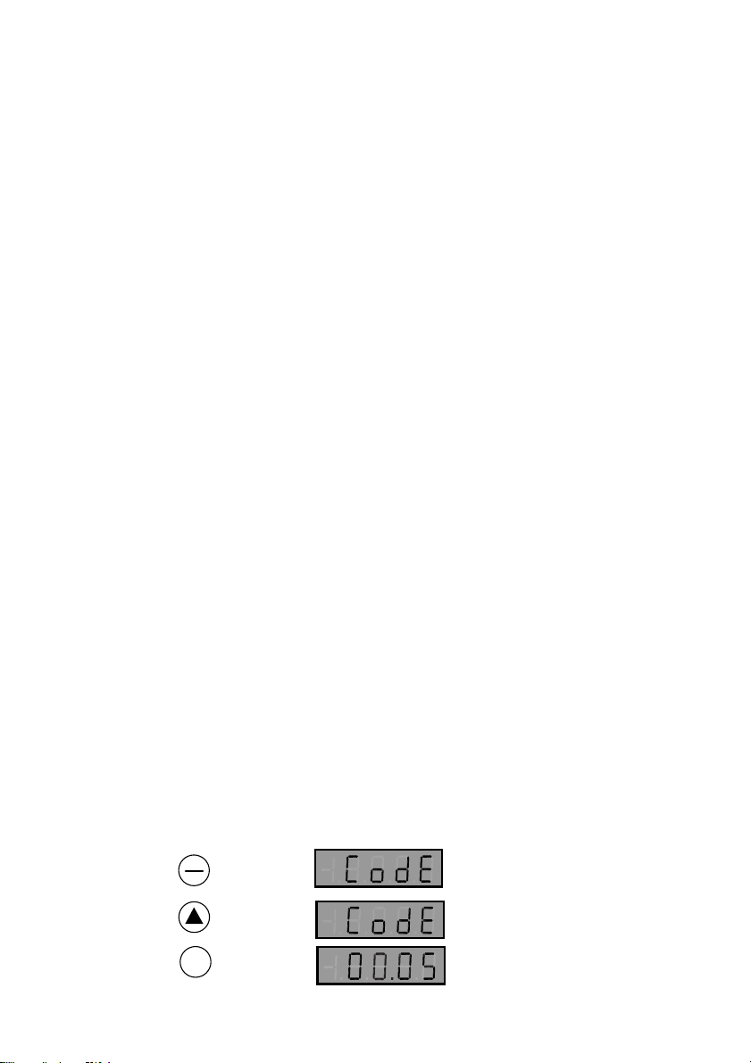
3.5.2 Diagnostic displays
The diagnostic displays are used to evaluate
abnormalities in the process stream.
• The standard electrical deviation (StdE) is
related to the level of electrical fluctuation in the
input signal reference. The value is displayed in
terms of volts, ie "0.02" represents 20 millivolts.
Nominal values range from 50 mV at low velocities
to 80 mV at maximum velocity. Higher values
indicate excessive fluid noise levels, or inadequate
earth ground. Use the Sensitivity adjustment (sec
3.4.1) to compensate and check the grounding
requirements (sec. 2.6).
• The standard flow deviation (StdF) is an overall
indication of the stability of the flow signal. It
incorporates the StdE, as well as mechanical factors
such as unstable flow profiles, misaligned sensors,
and coated electrodes. StdF is displayed as a
percentage of flow rate, typically from 5 to 8%.
StdF levels in excess of 10% indicate inadequate
installation or application standards.
If StdE value is high, the StdF will always be high.
If StdE is low but StdF is high, look for causes
related to sensor location, such as insufficient
upstream straight runs and sensor alignment. If the
StdF cannot be corrected by modifying the
installation, the Response function (sec 3.4.2) will
help to smooth the output signals.
Code entry is not necessary to change the display
setting.
Step: Press: To display:
1.
RUN
EDIT
2.
3.
ENTER
Example illustrates changing
display setting to StdE.
Use the up arrow to move
quickly to the display options.
RatE is the factory default
setting.
Selecting the StdE or StdF
diagnostic displays will not
affect or interrupt the outputs.
19
Page 25
3.6 Frequency output
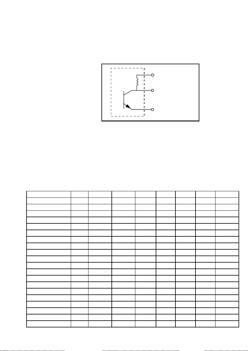
The frequency output from the FMG2550 Series is
an open collector signal that requires a 5 to 12
VDC reference.
Black (+V)
2KΩ
FMG2550
5 to 12 VDC in
Red (Signal out)
TS 2
Shield (Ground)
3.6.1 Product compatibility
If using the OMEGA FPM-9010A flow controller,
set input card switches for "1001" (5 VDC power
to sensor with pull up resistor).
3.7 Calibration data
Pipe type pipe pipe gpm/fps lpm/fps K A K A
size id pls/gal gpm/Hz pls/l lpm/Hz
U.S. pipe data
PVC sched 80 2 in. 1.91 8.95858 33.912 167.44 0.36 44.23 1.36
PVC sched 40 2 in. 2.05 10.2576 38.829 146.23 0.41 38.63 1.55
steel sch 5S 2 in. 2.25 12.3379 46.704 121.58 0.49 32.12 1.87
steel sch 10S 2 in. 2.16 11.3896 43.115 131.70 0.46 34.79 1.72
steel sch 40S 2 in. 2.07 10.459 39.592 143.42 0.42 37.89 1.58
steel sch 80S 2 in. 1.94 9.20375 34.84 162.98 0.37 43.05 1.39
PVC sched 80 2.5 in. 2.29 12.8375 48.596 116.85 0.51 30.87 1.94
PVC sched 40 2.5 in. 2.45 14.6341 55.397 102.50 0.59 27.08 2.22
steel sch 5S 2.5 in. 2.71 17.965 68.005 83.50 0.72 22.06 2.72
steel sch 10S 2.5 in. 2.64 16.9969 64.341 88.25 0.68 23.31 2.57
steel sch 40S 2.5 in. 2.47 14.8228 56.49 101.20 0.59 26.55 2.26
steel sch 80S 2.5 in. 2.32 13.2101 50.006 113.55 0.53 30.00 2.00
PVC sched 80 3 in. 2.86 20.0796 76.01 74.70 0.80 19.73 3.04
PVC sched 40 3 in. 3.04 22.6531 85.752 66.22 0.91 17.49 3.43
steel sch 5S 3 in. 3.33 27.2107 103 55.13 1.09 14.56 4.12
steel sch 10S 3 in. 3.26 26.0162 98.483 57.66 1.04 15.23 3.94
steel sch 40S 3 in. 3.07 23.042 87.224 65.10 0.92 17.20 3.49
steel sch 80S 3 in. 2.90 20.5876 77.933 72.86 0.82 19.25 3.12
20
Page 26

Pipe type pipe pipe gpm/fps lpm/fps K A K A
size id pls/gal gpm/Hz pls/l lpm/Hz
PVC sched 80 3.5 in. 3.33 27.0803 102.51 55.39 1.08 14.63 4.10
PVC sched 40 3.5 in. 3.52 30.3488 114.88 49.43 1.21 13.06 4.60
steel sch 5S 3.5 in. 3.83 35.9843 136.22 41.68 1.44 11.01 5.45
steel sch 10S 3.5 in. 3.76 34.6087 131.01 43.34 1.38 11.45 5.24
steel sch 40S 3.5 in. 3.55 30.816 116.65 48.68 1.23 12.86 4.67
steel sch 80S 3.5 in. 3.36 27.7026 104.87 54.15 1.11 14.30 4.19
PVC sched 80 4 in. 3.79 35.089 132.83 42.75 1.40 11.29 5.31
PVC sched 40 4 in. 4.00 39.1289 148.12 38.33 1.57 10.13 5.92
steel sch 5S 4 in. 4.33 45.9819 174.06 32.62 1.84 8.62 6.96
steel sch 10S 4 in. 4.26 44.4251 168.17 33.76 1.78 8.92 6.73
steel sch 40S 4 in. 4.03 39.6786 150.2 37.80 1.59 9.99 6.01
steel sch 80S 4 in. 3.83 35.8343 135.65 41.86 1.43 11.06 5.43
PVC sched 80 5 in. 4.77 55.6521 210.67 26.95 2.23 7.12 8.43
PVC sched 40 5 in. 5.02 61.592 233.15 24.35 2.46 6.43 9.33
steel sch 5S 5 in. 5.35 69.9366 264.74 21.45 2.80 5.67 10.59
steel sch 10S 5 in. 5.30 68.6343 259.81 21.85 2.75 5.77 10.39
steel sch 40S 5 in. 5.05 62.3557 236.04 24.06 2.49 6.35 9.44
steel sch 80S 5 in. 4.81 56.7076 214.66 26.45 2.27 6.99 8.59
PVC sched 80 6 in. 5.71 79.7865 302.03 18.80 3.19 4.97 12.08
PVC sched 40 6 in. 6.03 89.0406 337.06 16.85 3.56 4.45 13.48
steel sch 5S 6 in. 6.41 100.489 380.4 14.93 4.02 3.94 15.22
steel sch 10S 6 in. 6.36 98.9267 374.48 15.16 3.96 4.01 14.98
steel sch 40S 6 in. 6.07 90.0473 340.87 16.66 3.60 4.40 13.63
steel sch 80S 6 in. 5.76 81.2466 307.55 18.46 3.25 4.88 12.30
PVC sched 80 8 in. 7.57 140.096 530.33 10.71 5.60 2.83 21.21
PVC sched 40 8 in. 7.94 154.408 584.5 9.71 6.18 2.57 23.38
steel sch 5S 8 in. 8.41 173.018 654.95 8.67 6.92 2.29 26.20
steel sch 10S 8 in. 8.33 169.822 642.85 8.83 6.79 2.33 25.71
steel sch 40S 8 in. 7.98 155.928 590.26 9.62 6.24 2.54 23.61
steel sch 80S 8 in. 7.63 142.328 538.77 10.54 5.69 2.78 21.55
PVC sched 80 10 in. 9.49 220.605 835.09 6.80 8.82 1.80 33.40
PVC sched 40 10 in. 9.98 243.625 922.23 6.16 9.75 1.63 36.89
steel sch 5S 10 in. 10.48 268.966 1018.2 5.58 10.76 1.47 40.73
steel sch 10S 10 in. 10.42 265.794 1006.1 5.64 10.63 1.49 40.24
steel sch 40S 10 in. 10.02 245.779 930.38 6.10 9.83 1.61 37.22
steel sch 80S 10 in. 9.75 232.712 880.92 6.45 9.31 1.70 35.24
PVC sched 80 12 in. 11.29 312.252 1182 4.80 12.49 1.27 47.28
PVC sched 40 12 in. 11.89 346.019 1309.8 4.34 13.84 1.15 52.39
steel sch 5S 12 in. 12.44 378.713 1433.6 3.96 15.15 1.05 57.34
steel sch 10S 12 in. 12.39 375.796 1422.6 3.99 15.03 1.05 56.90
steel sch 40S 12 in. 12.00 352.51 1334.4 4.26 14.10 1.12 53.38
steel sch 80S 12 in. 11.75 337.975 1279.4 4.44 13.52 1.17 51.18
21
Page 27

DIN Standard Plastic Pipe
Pipe type pipe pipe gpm/fps lpm/fps K A K A
size id pls/gal gpm/Hz pls/l lpm/Hz
PP bar 10 63 51.4 10.02 37.943 149.63 0.40 39.53 1.52
PP bar 10 75 61.2 14.21 53.791 105.55 0.57 27.89 2.15
PP bar 10 90 73.6 20.55 77.797 72.98 0.82 19.28 3.11
PP bar 10 110 90 30.73 116.33 48.81 1.23 12.89 4.65
PP bar 10 125 102.2 39.63 150.01 37.85 1.59 10.00 6.00
PP bar 10 140 114.4 49.66 187.96 30.21 1.99 7.98 7.52
PP bar 10 160 130.8 64.92 245.71 23.11 2.60 6.10 9.83
PP bar 10 180 147.2 82.22 311.19 18.24 3.29 4.82 12.45
PP bar 10 200 163.6 101.56 384.39 14.77 4.06 3.90 15.38
PP bar 10 225 184 128.46 486.23 11.68 5.14 3.08 19.45
PP bar 10 250 204.4 158.53 600.03 9.46 6.34 2.50 24.00
PP bar 10 280 229 198.98 753.14 7.54 7.96 1.99 30.13
PP bar 10 315 257.6 251.79 953.01 5.96 10.07 1.57 38.12
PVDF bar 10 90 84.4 27.03 102.3 55.50 1.08 14.66 4.09
PVDF bar 10 110 103 40.25 152.36 37.26 1.61 9.84 6.09
PVDF bar 10 160 150 85.37 323.14 17.57 3.41 4.64 12.93
PVDF bar 10 200 187.6 133.54 505.44 11.23 5.34 2.97 20.22
PVDF bar 10 250 234.8 209.19 791.78 7.17 8.37 1.89 31.67
PVDF bar 16 63 57 12.33 46.661 121.67 0.49 32.15 1.87
PVDF bar 16 75 67.8 17.44 66.019 86.00 0.70 22.72 2.64
PVDF bar 16 90 81.4 25.14 95.161 59.66 1.01 15.76 3.81
PVDF bar 16 110 99.4 37.49 141.9 40.01 1.50 10.57 5.68
PVC bar 10 63 57 12.33 46.661 121.67 0.49 32.15 1.87
PVC bar 10 75 67.8 17.44 66.019 86.00 0.70 22.72 2.64
PVC bar 10 90 81.4 25.14 95.161 59.66 1.01 15.76 3.81
PVC bar 10 110 99.4 37.49 141.9 40.01 1.50 10.57 5.68
PVC bar 10 125 113 48.45 183.39 30.96 1.94 8.18 7.34
PVC bar 10 140 126.6 60.81 230.18 24.67 2.43 6.52 9.21
PVC bar 10 160 144.6 79.34 300.29 18.91 3.17 5.00 12.01
PVC bar 10 180 162.8 100.57 380.64 14.92 4.02 3.94 15.23
PVC bar 10 200 180.8 124.03 469.47 12.09 4.96 3.20 18.78
PVC bar 10 225 203.4 156.98 594.17 9.56 6.28 2.52 23.77
PVC bar 16 63 53.6 10.90 41.261 137.60 0.44 36.35 1.65
PVC bar 16 75 63.8 15.44 58.459 97.12 0.62 25.66 2.34
PVC bar 16 90 76.6 22.26 84.269 67.37 0.89 17.80 3.37
PVC bar 16 110 93.6 33.24 125.82 45.12 1.33 11.92 5.03
PVC bar 16 125 106.4 42.96 162.59 34.92 1.72 9.23 6.50
PVC bar 16 140 119.2 53.91 204.06 27.82 2.16 7.35 8.16
PVC bar 16 160 136.2 70.39 266.42 21.31 2.82 5.63 10.66
22
Page 28

3.8 Custom K-factor calculation
K-factors can be calculated for any pipe using the
pipe id and the ft/s engineering unit options. The
procedure is based on the relationship between
the frequency output and the flow velocity:
20 ft/s = 500 Hz. therefore 1 ft/s = 25 Hz.
1. Install the FMG2550 Series Magmeter in pipe
according to sec 2.2.
2. Enter the pipe ID into the menu, and select feet
per second (FPS) as the engineering unit.
3. Establish a stable flow rate in the pipe. It is not
important to know what the rate is, just that the
rate be stable.
4. Read the flow rate from display and multiply
the display value (ft/s) by 25. (frequency can
be verified by monitoring TS2 if desired.)
Record the result _____ ft/s = ________Hz.
5. Change the display to read in desired
engineering units. Do not change flow rate!
Record the result _____GPM = ________Hz.
6. Divide the flow rate by the frequency result of
step 3. Record the result:
Example illustrates calculating
a custom K-factor in GPM for
pipe with 3.068 in. id.
Unit = ft/s
Display = 5.2 ft/s
5.2 x 25 = 130 Hz
5.2 ft/s = 130 Hz.
Unit = GPM
Display = 120 GPM
120 GPM = 130 Hz.
Flow Rate/Hz = A =_______________
7. K = 60 / A = _________________
A = 120 ÷ 130 = 0.92
K = 60 ÷ 0.92 = 65.2
23
Page 29
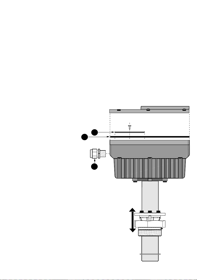
3.9 Spare parts list
2
3
1
1. Access cover 3-2550.374
2. Gasket, outer cover 1222-0439
3. Cable connector* (standard)
for .125 to .187 o.d. cable FMG255-F
Cable connector (optional)
for .187 to .250 od cable 1500-0102
4. Fuse, 3/4 A slo-blo FMG255-CP
5. Installation tool FMG255-T
*
Additional connector sizes available
from Hubbell Inc.:
Cable diameter Hubbell part no.
0.250 to 0.312 #SHC-1010-ZP
0.312 to 0.375 #SHC-1011-ZP
0.375 to 0.437 #SHC-1012-ZP
Hubbell Incorporated
State Street and Bostwick Avenue
Bridgeport Connecticut 06605-0933
Phone: (203) 337-3100
Fax: (203) 368-6245
24
Page 30

General Data
Flow velocity range: 0.1 to 6 m/s
(0.3 to 20 ft/s)
Accuracy: ±2% of reading or
±0.05 ft/s whichever
is greater
Temperature coefficient: ≤0.015% per °C
Pipe size: 51 to 305 mm
(2 to 12 in.),
metal or plastic
Response time: User Selectable:
instantaneous/5/10/15/
20/30/40/60/80 s.
Isolated current output: 4 to 20 mA or 0 to 20 mA,
into 600 Ω max. load
Frequency output: 0 to 20 ft/s = 0 to 500 Hz
isolated, open collector
50% duty cycle, (5 to 12 VDC)
Specifications
25
Page 31

Materials
Enclosure: Die cast aluminum,
Nema 4/IP65
Sensor body: 316 stainless steel
Sensor tip: PFA Sealing tape®
Electrodes: 316 stainless steel
Retaining ring: 316 stainless steel
Threaded nut: 316 stainless steel
Internal o-ring: FPM Viton®
Electrical Data
Power Requirements: 24 VDC ± 10%, 600 mA
Recommended power supply (or equivalent):
OMEGA Part # U24Y101
Magnetic field: Bipolar DC
26
Input signal impedance: >10000 MΩ
Page 32

Ambient Conditions
Humidity: 100% RH,non-condensing
Liquid temperature: 0 to 100°C
(32 to 212 °F)
Ambient temperature: -20 to 80°C
(-4 to 176°F)
Minimum liquid conductivity: 5 µS/cm
Maximum operating pressure: 17 bar (250 psig)
27
Page 33

Notes:
28
Page 34

Page 35

WARRANTY/DISCLAIMER
OMEGA ENGINEERING, INC. warrants this unit to be free of defects in materials and workmanship for a
period of 13 months from date of purchase. OMEGA’s WARRANTY adds an additional one (1) month
grace period to the normal one (1) year product warranty to cover handling and shipping time. This
ensures that OMEGA’s customers receive maximum coverage on each product.
If the unit malfunctions, it must be returned to the factory for evaluation. OMEGA’s Customer Service
Department will issue an Authorized Return (AR) number immediately upon phone or written request.
Upon examination by OMEGA, if the unit is found to be defective, it will be repaired or replaced at no
charge. OMEGA’s WARRANTY does not apply to defects resulting from any action of the purchaser,
including but not limited to mishandling, improper interfacing, operation outside of design limits,
improper repair, or unauthorized modification. This WARRANTY is VOID if the unit shows evidence of
having been tampered with or shows evidence of having been damaged as a result of excessive corrosion;
or current, heat, moisture or vibration; improper specification; misapplication; misuse or other operating
conditions outside of OMEGA’s control. Components which wear are not warranted, including but not
limited to contact points, fuses, and triacs.
OMEGA is pleased to offer suggestions on the use of its various products. However,
OMEGA neither assumes responsibility for any omissions or errors nor assumes liability for any
damages that result from the use of its products in accordance with information provided
by OMEGA, either verbal or written. OMEGA warrants only that the parts manufactured by it
will be as specified and free of defects. OMEGA MAKES NO OTHER WARRANTIES OR
REPRESENTATIONS OF ANY KIND WHATSOEVER, EXPRESS OR IMPLIED, EXCEPT THAT OF
TITLE, AND ALL IMPLIED WARRANTIES INCLUDING ANY WARRANTY OF MERCHANTABILITY
AND FITNESS FOR A PARTICULAR PURPOSE ARE HEREBY DISCLAIMED. LIMITATION OF
LIABILITY: The remedies of purchaser set forth herein are exclusive, and the total liability of
OMEGA with respect to this order, whether based on contract, warranty, negligence,
indemnification, strict liability or otherwise, shall not exceed the purchase price of the
component upon which liability is based. In no event shall OMEGA be liable for
consequential, incidental or special damages.
CONDITIONS: Equipment sold by OMEGA is not intended to be used, nor shall it be used: (1) as a “Basic
Component” under 10 CFR 21 (NRC), used in or with any nuclear installation or activity; or (2) in medical
applications or used on humans. Should any Product(s) be used in or with any nuclear installation or
activity, medical application, used on humans, or misused in any way, OMEGA assumes no responsibility
as set forth in our basic WARRANTY / DISCLAIMER language, and, additionally, purchaser will indemnify
OMEGA and hold OMEGA harmless from any liability or damage whatsoever arising out of the use of the
Product(s) in such a manner.
RETURN REQUESTS/INQUIRIES
Direct all warranty and repair requests/inquiries to the OMEGA Customer Service Department. BEFORE
RETURNING ANY PRODUCT(S) TO OMEGA, PURCHASER MUST OBTAIN AN AUTHORIZED RETURN
(AR) NUMBER FROM OMEGA’S CUSTOMER SERVICE DEPARTMENT (IN ORDER TO AVOID
PROCESSING DELAYS). The assigned AR number should then be marked on the outside of the return
package and on any correspondence.
The purchaser is responsible for shipping charges, freight, insurance and proper packaging to prevent
breakage in transit.
FOR
WARRANTY RETURNS, please have the
following information available BEFORE
contacting OMEGA:
1. Purchase Order number under which the
product was PURCHASED,
2. Model and serial number of the product under
warranty, and
3. Repair instructions and/or specific problems
relative to the product.
OMEGA’s policy is to make running changes, not model changes, whenever an improvement is possible. This affords
our customers the latest in technology and engineering.
OMEGA is a registered trademark of OMEGA ENGINEERING, INC.
© Copyright 2000 OMEGA ENGINEERING, INC. All rights reserved. This document may not be copied, photocopied,
reproduced, translated, or reduced to any electronic medium or machine-readable form, in whole or in part, without the
prior written consent of OMEGA ENGINEERING, INC.
FOR NON-WARRANTY REPAIRS,
for current repair charges. Have the following
information available BEFORE contacting OMEGA:
1. Purchase Order number to cover the COST of
the repair,
2. Model and serial number of the product, and
3. Repair instructions and/or specific problems
relative to the product.
consult OMEGA
Page 36

Where Do I Find Everything I Need for
Process Measurement and Control?
OMEGA…Of Course!
Shop online at www.omega.com
TEMPERATURE
Thermocouple, RTD & Thermistor Probes, Connectors, Panels & Assemblies
Wire: Thermocouple, RTD & Thermistor
Calibrators & Ice Point References
Recorders, Controllers & Process Monitors
Infrared Pyrometers
PRESSURE, STRAIN AND FORCE
Transducers & Strain Gages
Load Cells & Pressure Gages
Displacement Transducers
Instrumentation & Accessories
FLOW/LEVEL
Rotameters, Gas Mass Flowmeters & Flow Computers
Air Velocity Indicators
Turbine/Paddlewheel Systems
Totalizers & Batch Controllers
pH/CONDUCTIVITY
pH Electrodes, Testers & Accessories
Benchtop/Laboratory Meters
Controllers, Calibrators, Simulators & Pumps
Industrial pH & Conductivity Equipment
DATA ACQUISITION
Data Acquisition & Engineering Software
Communications-Based Acquisition Systems
Plug-in Cards for Apple, IBM & Compatibles
Datalogging Systems
Recorders, Printers & Plotters
HEATERS
Heating Cable
Cartridge & Strip Heaters
Immersion & Band Heaters
Flexible Heaters
Laboratory Heaters
ENVIRONMENTAL
MONITORING AND CONTROL
Metering & Control Instrumentation
Refractometers
Pumps & Tubing
Air, Soil & Water Monitors
Industrial Water & Wastewater Treatment
pH, Conductivity & Dissolved Oxygen Instruments
6-2550.090-OM/(F-8/02) M-2974/0802
 Loading...