

Page 1

User’s Manual
Shop online at
omega.com
E-mail: [email protected]
For latest product manuals:
www.omegamanual.info
SM
FMC-5000 Series
Coriolis Mass Flowmeters
Page 2

®
omega.com [email protected]
Servicing North America:
U.S.A. Omega Engineering, Inc.
Headquarters: Toll-Free: 1-800-826-6342 (USA & Canada only )
Customer Service: 1-800-622-2378 (USA & Canada only)
Engineering Service: 1-800-872-9436 (USA &
Tel: (203) 359-1660 Fax: (203)
359-7700
E-mail: [email protected]
For Other Locations Visit
omega.com/worldwide
Canada only)
The information contained in this document is believed to be correct, but OMEGA accepts no liability for any errors it
contains, and reserves the right to alter specifications without notice.
2 / 36
Page 3

CAUTION: To reduce the risk of ignition of hazardous atmospheres, disconnect
the equipment supply circuit before opening. Keep assembly tightly closed when in
operation.
WARNING: To Reduce The Risk Of Ignition Of Hazardous Atmospheres, Conduit
Runs Must Have a Sealing Fitting Connected Within 18 in. of the Enclosure.
This manual includes the structure, principle, specifications, usage, applicable scope
and precautions of the Mass Flowmeter sensor and transmitter. Be sure to read the
manual before installation and operation. For more details about the product, please
contact Omega.
If this transmitter has explosion-proof certification, no one is allowed to replace parts
and components without authorization.
3 / 36
Page 4
FMC-5000 Series Mass Flowmeter
CAUTION: ............................................................................................................... 3
1.1 Introduction .................................................................................................. 5
1.2 Principle ........................................................................................................ 5
1.3 Features ........................................................................................................ 6
2.1 Main Technical Specifications ........................................................................ 7
2.2 Specification of Function ............................................................................. 11
2.3 Environment Limitation ............................................................................... 12
2.4 Outlines and Dimensions ............................................................................. 13
2.5 Weights ....................................................................................................... 14
3.1 Brief ............................................................................................................ 15
3.2 Installation .................................................................................................. 15
3.3 Direction ..................................................................................................... 17
3.4 Sensor Installation ....................................................................................... 18
3.5 Wiring ......................................................................................................... 18
3.6 Start-up ....................................................................................................... 20
4.1 Power Wiring ............................................................................................... 21
4.2 Current Output Wiring ................................................................................ 22
4.3 Pulse Output Wiring .................................................................................... 23
4.4 RS485 Output Wiring ................................................................................... 24
5.1 General........................................................................................................ 25
5.2 Configuration Parameter ............................................................................. 25
5.3 Calibration ................................................................................................... 27
7.1 Overview ..................................................................................................... 34
7.2 Diagnostic Tool ............................................................................................ 34
7.3 Sensor ......................................................................................................... 35
7.4 Power and connection ................................................................................. 35
8.1 The explosion-proof grades of FMC Coriolis Meter ..................................... 36
4 / 36
Page 5

General
1.1 Introduction
FMC-5000 Series Coriolis Mass Flowmeter (here after FMC Coriolis Meter) is designed according
to the Coriolis Force Principle. It is widely used for the process detecting and custody transfer/fiscal
unit in many industries such as petroleum, petro-chemical, chemical industry, pharmacy, paper
making, food, energy, and so on. As an advanced flow and density measurement instrument, it is
widely used in the measurement of Liquids, Gas and Slurries.
1.2 Principle
FMC Coriolis Meter is designed according to the principle of Coriolis force. Under the alternating
current effect, the electromagnetic coils mounted on the measuring tube will make two parallel
measuring tubes vibrating at a certain fixed frequency. Whenever mass (either liquid or air) flows
through the measuring tubes, Coriolis force is generated, causing a “bending” or “deflection” in the
top of the tubes. This deflection is sensed as a phase shift between two electronic pick-ups mounted
on the tubes. The degree of phase shift is directly proportional to the mass flow within the tubes.
The mass flow rate can be calculated by detecting the phase shift of the tubes.
The vibration frequency of measuring tube is determined by the total mass of measuring tube and
inner mass flow. The vibration frequency of measuring tube changes over the changes of mass
flow density. Thus, the flow density can be calculated.
Working together with the measuring circuit, the temperature sensor mounted on the measuring
tubes can obtain the real-time temperature value.
5 / 36
Page 6

1.3 Features
Compared to traditional flow measurement methods, FMC Coriolis Meters have the following
obvious advantages:
1.3.1 Ability to directly measure the mass flow rate in the measuring tubes without any
conversions, which avoids intermediate measurement errors. The mass flow is measured with high
accuracy, good repeatability and a wide turndown ratio.
1.3.2 A wide range of flows, such as the steady uniform flows of common viscosity fluids, high
viscosity fluids, non-Newtonian fluid, slurries containing solid components and liquids containing a
little air.
1.3.3 With little vibration, the measuring tube can be regarded as no-moving parts, which will
reduce the meter maintenance, and ensure the stability and long life.
1.3.4 Besides the mass flow measurement, density, temperature and even consistency can also
be measured and output.
6 / 36
Page 7
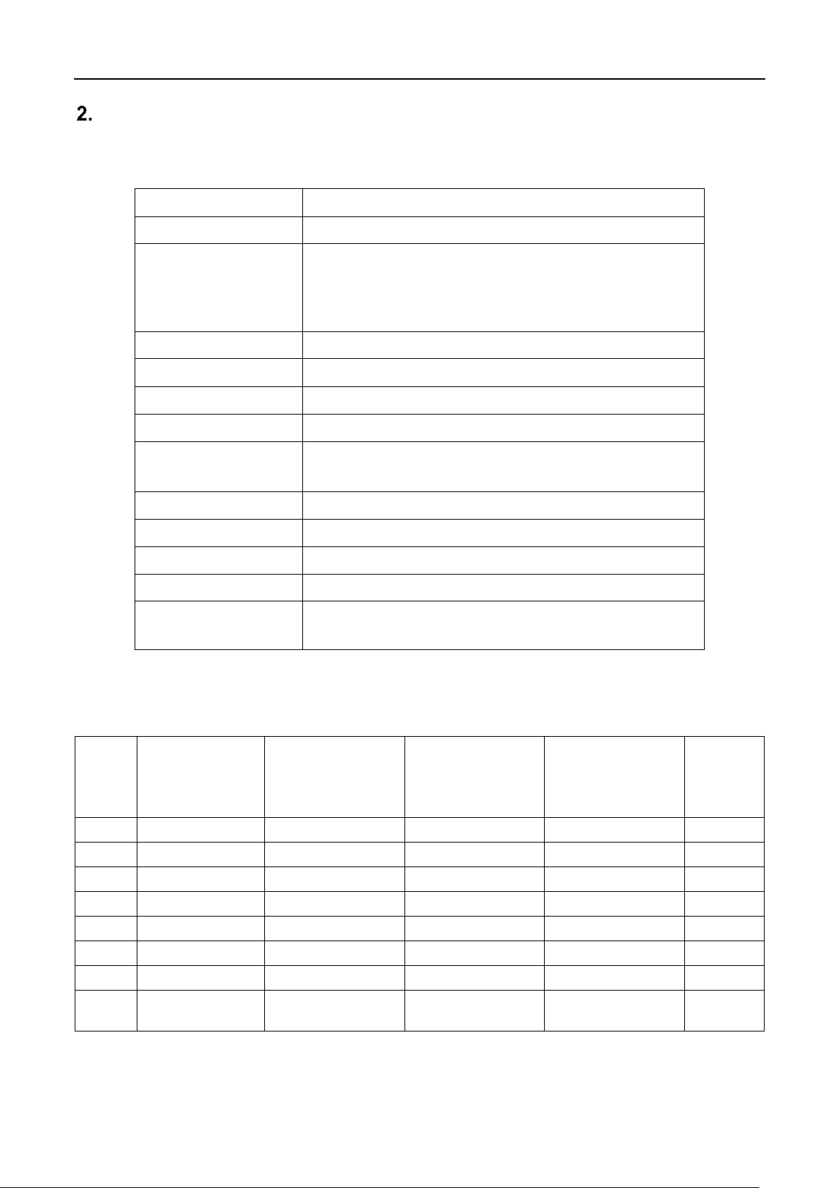
Technical Specifications
DN(mm)
15 ~ 200
Medium
Liquid, Gas, Slurry
Type / Medium Temp.
Integrate type: ( -50 ~ 125) ℃
Remote type: ( -50 ~ 200) ℃ (-R Option)
Remote type with high temp: ( -50 ~ 300) ℃ (Custom)
Sensor
Micro-bend type
Certification
Ex-proof (Optional)
Power Supply
18-36V dc (Standard), 85-265V ac (Optional)
Output Port
RS485
Pressure (MPa)
1.6 MPa (Standard)
2.5, 4.0 or 6.3 (Optional)
Output Signal
4~20mA, pulse
Accuracy
0.1%, 0.2%, 0.5% (Depending on Model)
Digital Communication
RS-485 Modbus (Standard), HART (Optional)
Hygienic Type
Sanitary Flange Option
Process Connection
150# ANSI (Standard)
DIN or JIS (Optional)
DN
(mm)
Allowable Flow
Range (kg/h)
Normal Flow
Range for
Accuracy 0.1%
(kg/h)
Normal Flow
Range for
Accuracy 0.2%
(kg/h)
Normal Flow
Range for
Accuracy 0.5%
(kg/h)
Stability
of Zero
Point
(kg/h)
15
20~3000
200~3000
150~3000
100~3000
0.09
25
80~8000
600~8000
400~8000
300~8000
0.25
40
240~24000
2400~24000
1200~24000
1000~24000
1
50
500~45000
5000~45000
2500~45000
2000~45000
2
80
800~120000
8000~120000
7000~120000
6000~120000
3.5
100
1500~200000
18000~200000
12000~200000
10000~200000
7
150
5000~500000
50000~500000
35000~500000
30000~500000
23
200
10000~
1000000
100000~
1000000
70000~
1000000
50000~
1000000
45
2.1 Main Technical Specifications
Table1: Main Technical Specifications
2.1.1 Flow Range
Table 3: Flow Range of Micro-bend type sensor (for Liquid)
7 / 36
Page 8
DN
(mm)
Measurable Flow
Range (kg/h)
Flow Range with Accuracy
0.5% (kg/h)
Stability of Zero Point
(kg/h)
15
15 ~ 3000
75 ~ 3000
0.12
25
40 ~ 8000
200 ~ 8000
0.32
40
160 ~ 32000
800 ~ 32000
1.2
50
250 ~ 50000
1250 ~ 50000
2
80
700 ~ 140000
3500 ~ 140000
6
100
1000 ~ 200000
5000 ~ 200000
8
150
2500 ~ 500000
12500 ~ 500000
20
DN
(mm)
Start Flow (Nm3/h)
Flow Range with Accuracy 0.5%
(Nm3/h)
Stability of Zero
Point(Nm3/h)
15
12.50
62.5 ~ 2500.0
0.11
25
33.33
166.7 ~ 6666.7
0.28
40
133.33
666.7 ~ 26666.7
1
50
208.33
1041.7 ~ 41666.7
1.6
80
583.33
2916.7 ~ 116666.7
5
100
833.33
4166.7 ~ 166666.7
6.7
150
2083.33
10416.7 ~ 416666.7
18
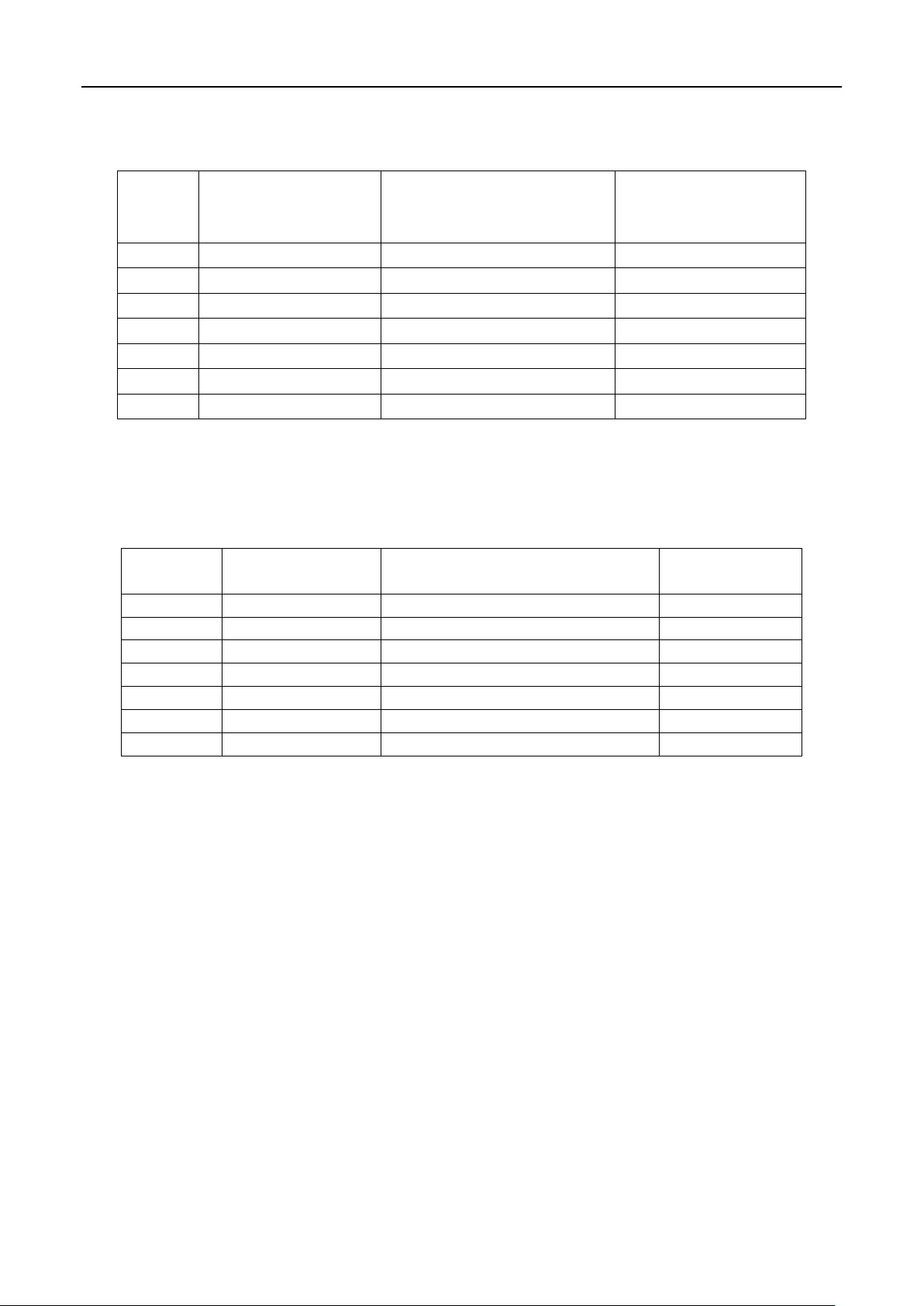
Table 4: Flow Range for gas mass flow (Air)
Table 5: Flow range of Volume for Air under standard temperature and pressure condition
(hereafter called “standard condition”)
8 / 36
Page 9
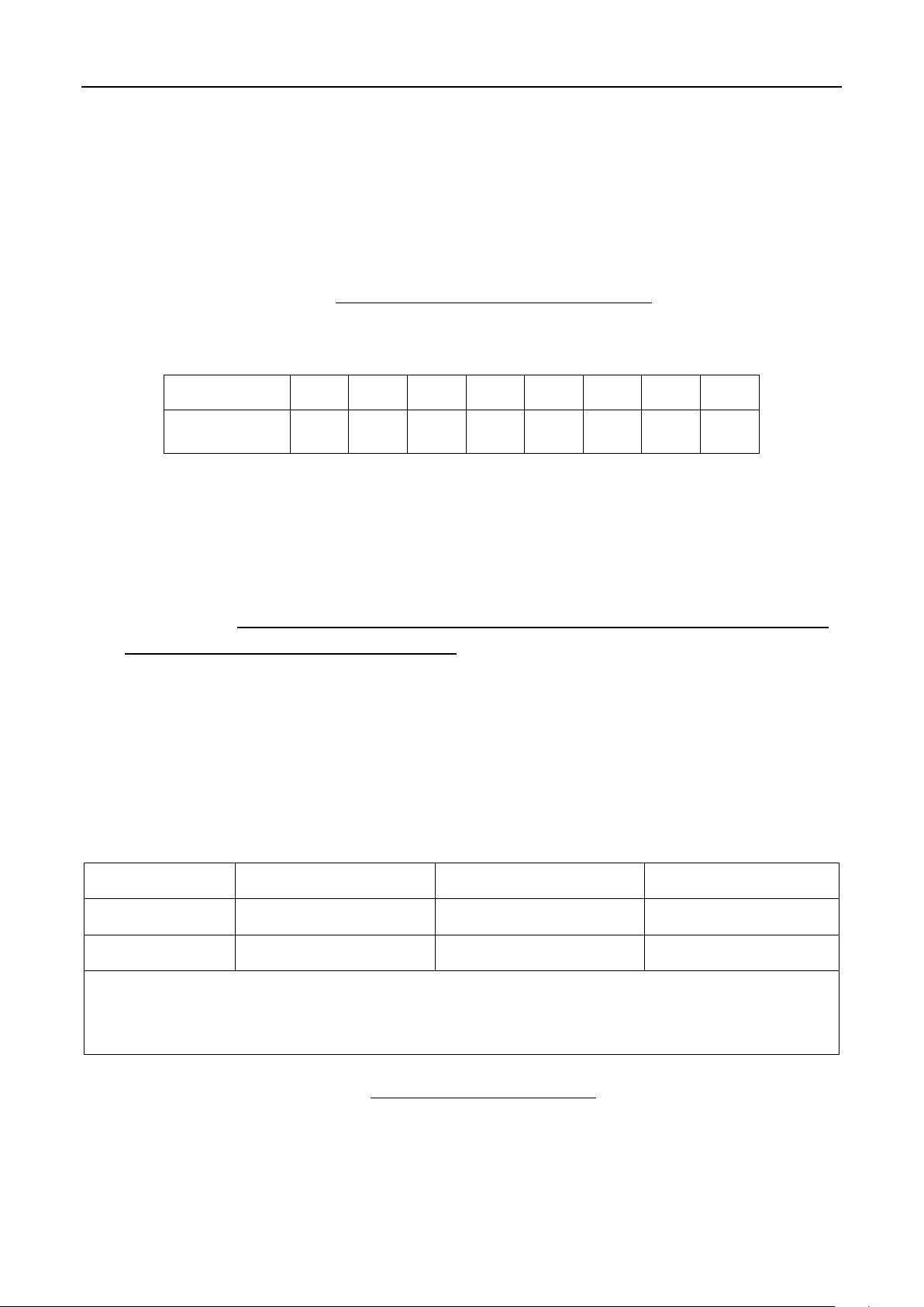
Table 6: Flow rate factor for calculating medium speed
Volume Flowrate under working condition
Flow Rate Factor
DN (mm)
15
25
40
50
80
100
150
200
Flow Rate
Factor
0.362
1.558
1.634
3.535
8.338
15.89
26.15
58.84
Accuracy
0.1%
0.2%
0.5%
Basic error
±0.10%
±0.20%
±0.50%
Repeatability
±0.05%
±0.10%
±0.25%
Accuracy is calculated based on the water measurement under the condition of +20℃~25℃
and 0.1MPa~0.2MPa.
%100
FlowousInstantane
PointZero ofStability
Accuracy
In many cases, we need to know the flow rate of the medium while using the FMC Coriolis Meter
for Air measurement. Connection size reducing is common for mass flow meter Air measurement
applications, thus the flow rate of the FMC Coriolis Meter needs to be checked according to the
formula below:
Inside Medium Flow Rate =
Note:
The Gaseous medium flow velocity is usually much higher than liquid when measured by a
flow meter, so there will be noise caused by gas medium and tube wall of flow meter under
high speed gas flow and if the noise become large enough, the signal of flow meter will be
influenced, so please use FMC Coriolis Meter for gaseous medium measurement
at speed less than 1/3 Mach (110m/s)!
Please use FMC Coriolis Meters for Gas with a
pressure drop no more than 0.2Mpa!
2.1.2 Accuracy, Basic error and Repeatability
Table 7: Mass flow measurement accuracy
9 / 36
Page 10

2.1.3 Density Measuring
Density Range
(0.2~3.0)g/cm3
Basic Error
±0.002g/cm3
Repeatability
±0.001g/cm3
Temperature
(-50~+125)℃
Integrated Type
(-50~+125)℃
Integrated Type
Range
(-50~+200)℃
Separate Type
(-50~+300)℃
High Temperature Separate Type (Optional)
(-125~+125)℃
Low Temperature Separate Type (Optional)
Basic Error
≤±1.0℃
Table 8
2.1.4 Temperature Measuring
Table 9
10 / 36
Page 11
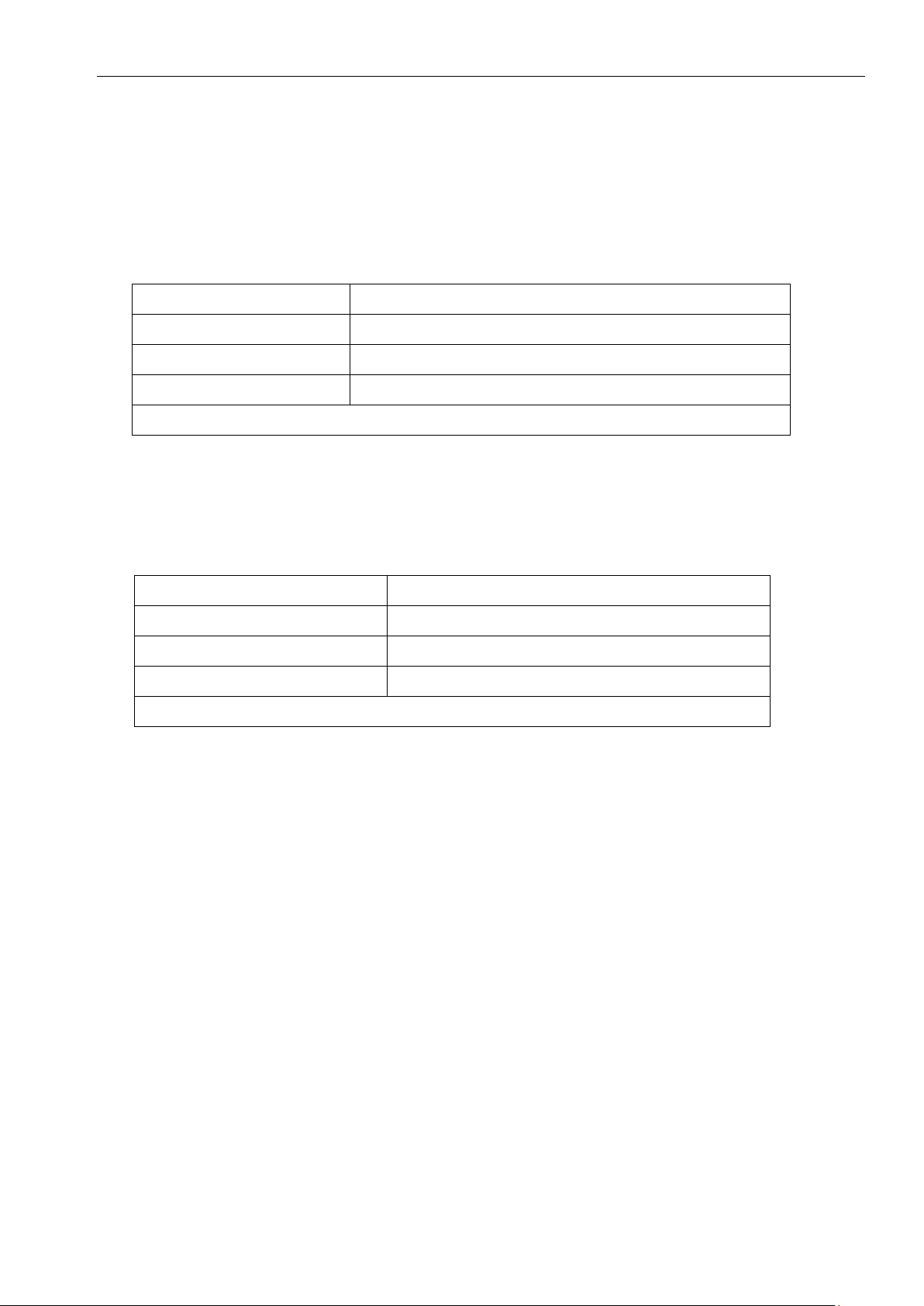
2.2 Specification of Function
Output Range
(4~20) mA
Resolution
0.000244mA
Basic Error
0.2%F. S
Temperature Influence
±0.005%F. S/℃
External resistor should be 250~600Ω
Output Range
(0~10) kHz
Resolution
0.152Hz
Basic Error
±0.075%
Temperature Influence
±0.001%F. S/℃
Capability of Outrange is 12kHz
2.2.1 Current Output
4-20mA Passive Current Output can be configured to indicate the mass flow, volume flow,
density or water ratio.
Table 10
2.2.2 Pulse Output
Active Pulse Output can be configured to indicate the mass flow, volume flow, density or water
ratio.
Table 11
2.2.3 Low Flow Cut-off
When the mass flow value is lower than the value of Low Flow Cutoff, the FMC Coriolis Meter
will output flow rate of zero, and the totalizer will stop accumulating. The value of Low Flow
Cutoff is usually set to be 1% of the maximum flow rate.
2.2.4 RS485 Output
RS485 output is compatible to the RTU mode of MODBUS protocol. For details, please contact
Omega.
11 / 36
Page 12
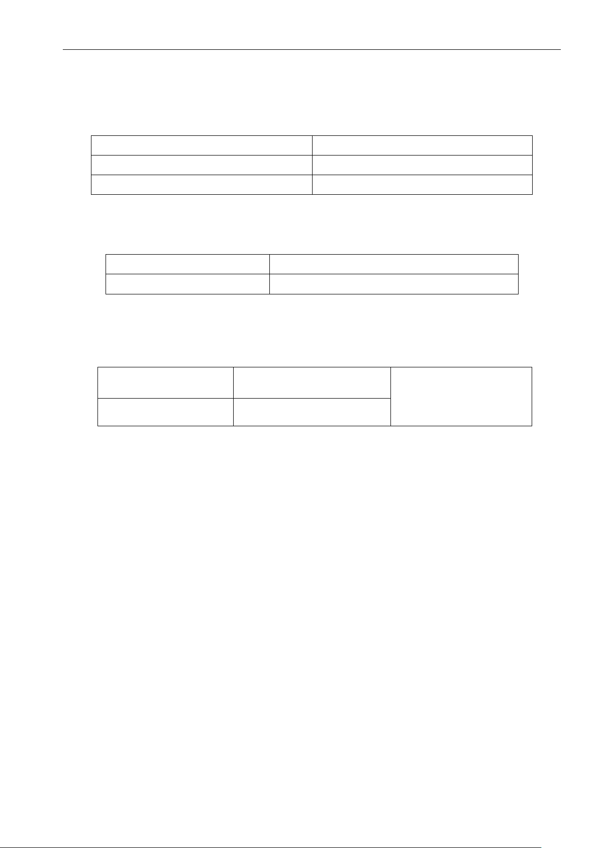
2.3 Environment Limitation
Frequency Range
(10~2000) Hz
Maximum Acceleration
2g (19.6m/s2)
Maximum Vibration Cycles
50
Working Temperature
(-40~+55) ℃
Storage Temperature
(-40~+70) ℃
Working Humidity
<90%
+25℃
No condensation
Storage Humidity
<95%
2.3.1 Environment vibration
Table 12
2.3.2 Environment temperature
Table 13
2.3.3 Environment humidity
Table 14
2.3.4 Enclosure Grade: IP65
2.3.5 Power Consumption
The normal power consumption for flow meter is 10W, and the max. Power consumption is 15W.
12 / 36
Page 13
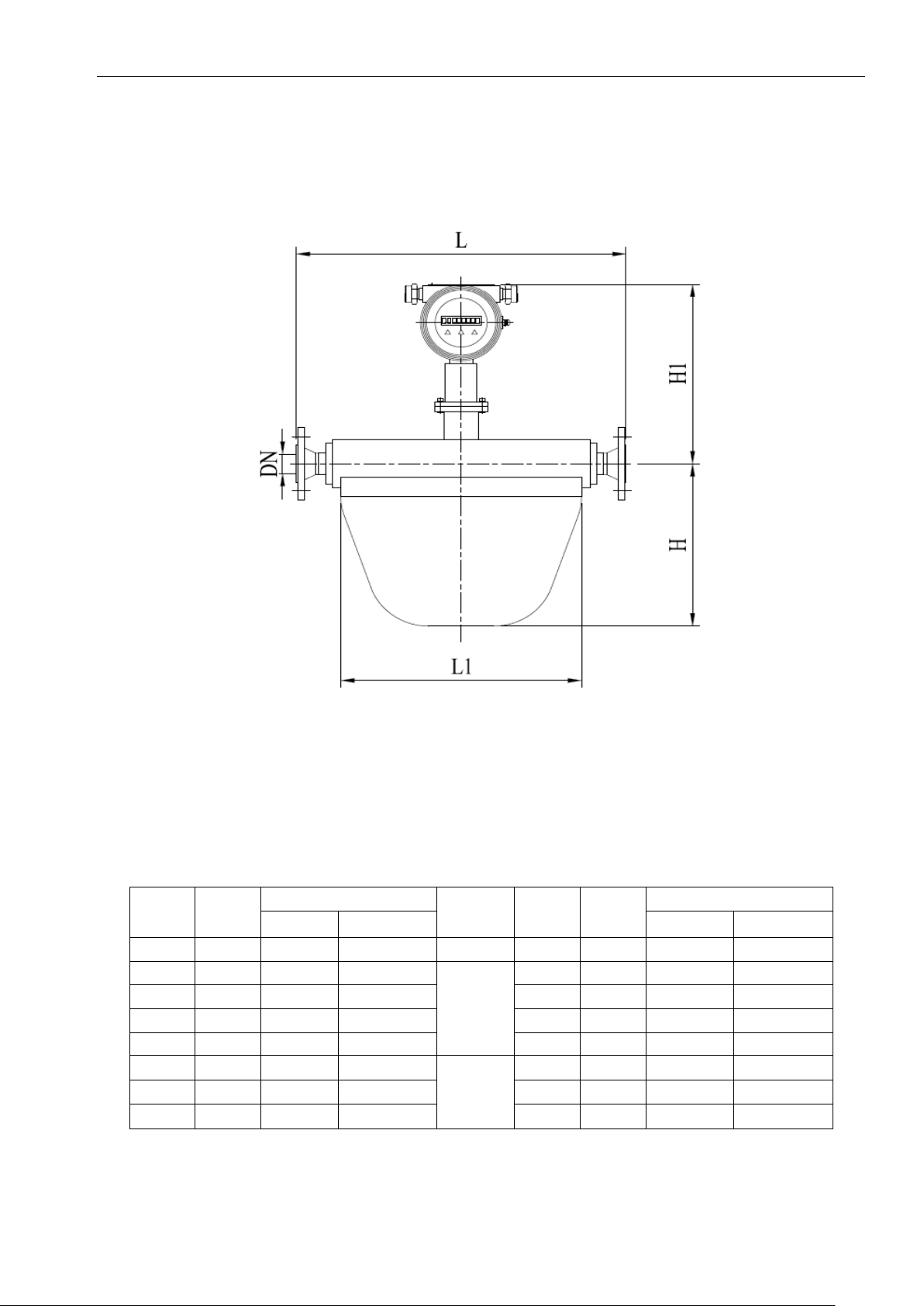
2.4 Outlines and Dimensions
FMC-
DN
L
ΔL
(mm)
L1
H
H1
<40Mpa
>63Mpa
Compact
Remote
015
15
400
414
±1.5
280
191
298
213
025
25
500
536
±2.5
360
258
302
218
040
40
600
634
460
306
315
230
050
50
800
828
640
410
325
240
080
80
900
928
700
495
350
265
100
100
1130
1156
±3.5
860
663
370
285
150
150
1450
1490
1200
902
400
316
200
200
1800
1844
1450
1170
426
342
Micro-bend Type
Table16: Dimensions of Micro-bend type Unit: mm
13 / 36
Page 14
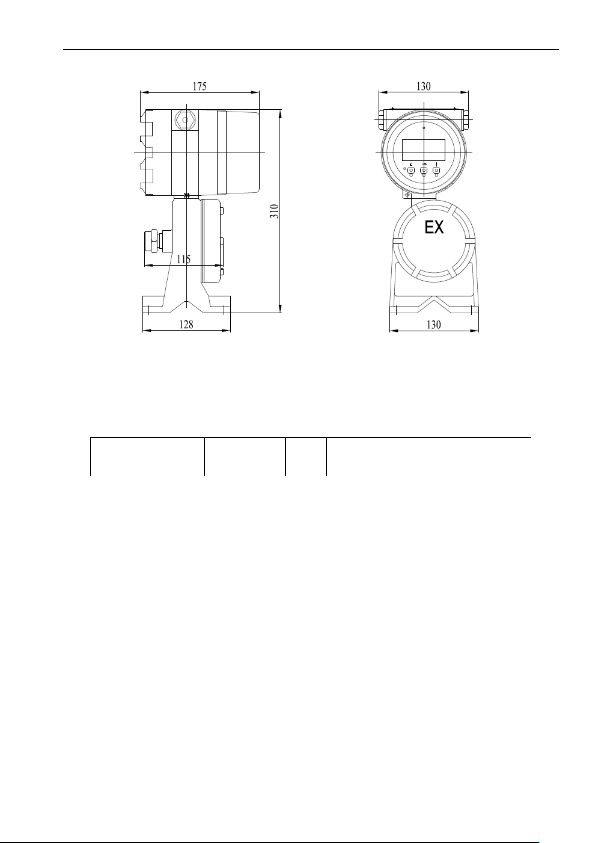
DN ( mm )
15
25
40
50
80
100
150
200
Micro-bend type
12
15
25
38
78
135
265
430
Drawing 6:Dimensions for remote type transmitter (unit: mm)
2.5 Weights
Table 17: net weights Unit: kg
Note: transmitter for remote type is 5kg extra.
14 / 36
Page 15

Installation
3.1 Brief
3.1.1 Pre-installation
This section offers instructions for installation, wiring, operation, and trouble-shooting. The user
must read this manual carefully before installation and operation, because improper installation
may cause incorrect measurement and even damage the flow meter.
3.1.2 Safety
When the flow meter is going to be installed in the dangerous area, please confirm that the
flow meter’s explosion-proof class is consistent with the environmental requirements in
order to avoid the potential danger.
Make sure that the power is shut off to avoid electric shock when installing the transmitter.
Follow the installation and operation instructions to ensure the safe operation.
3.1.3 Components
FMC Coriolis Meter is made up of a sensor (measuring tubes) and a transmitter, which can be
installed integrally or separately. When FMC Coriolis Meter is installed separately, the sensor and
transmitter should be connected by special Nine-Core Cable.
3.2 Installation
3.2.1 Installation Process
Step 1: Location: Determine the sensor installation location, which should take the installation
area, pipeline, transmitter location and valves into account.
Step 2: Direction: Determine the sensor installation direction in the pipeline.
Step 3: Installation: Install the sensor and transmitter in the pipeline.
Step 4: Connection: When FMC Coriolis Meter is installed separately; the sensor and
transmitter should be connected by special Nine-Core Cable.
Step 5: Start-up.
3.2.2 Position selection
The sensor should be placed away from interference sources (such as a pump) which may
cause pipe mechanical vibration. If sensors are used in series along the same line, care must
15 / 36
Page 16

be taken to avoid the mutual influence due to vibration resonance. The distance between
Cable Model
Cable Specification
Max. Length
Special Nine-Core Cable
Special
300m
Current Power Line
18AWG(0.8mm2)
300m
RS485 Communication Line
22AWG(0.35mm2)
300m
sensors should be no less than 2 meters.
When installing the sensor, pay attention to the expansion and contraction of the process
pipeline due to temperature changes. It is strongly recommended that the sensor not be
installed near an expansion joint of the process pipeline. Otherwise, the pipe expansion and
contraction of the pipeline will bring about transverse stress which will affect the sensor‘s zero
which will affect the measurement accuracy.
The sensor should be placed at least 5M away from industrial electromagnetic interference
sources such as large power motors and transformers.
The sensor should be placed in the position where its measuring tube is always filled with fluids
and a certain pressure at the outlet is maintained, thus it should be placed in a lower position
of the pipeline.
Basic requirement: Install the FMC Coriolis Meter in a lower position of the pipeline so that the
fluid can fill the sensor during the process of zero-point calibration and operation. The
transmitter should be installed in the environment with temperature from -40~+55 ℃ and
humidity <90%.
Dangerous area: Please confirm the explosion-proof class indicated in the nameplate of FMC
Coriolis Meter matches the application environment regulation before installation.
Straight pipe: The FMC Coriolis Meter does not require the special straight pipe upstream or
downstream. However, if more than one mass flow transmitters are installed in the same pipe,
please ensure the length of pipe between any two sets is more than 2 meters.
3.2.3 Maximum length of cable: shown in Table 22
16 / 36
Page 17
3.2.4 Working temperature of sensor: shown in Table 23
Integral Type
(-50~+125) ℃
Separate Type (-R)
(-50~+200) ℃
High temperature Separate Type
(Optional)
(-50~+300) ℃
3.2.5 Valve
It is necessary to conduct the zero-point calibration once the installation is completed. The
downstream stop valve must be closed before zero-point calibration, and then close the upstream
stop valve.
3.3 Direction
3.3.1Basic requirement:
The FMC Coriolis Meter should be installed in the orientation that can ensure the measuring tube
is filled with the medium being measured.
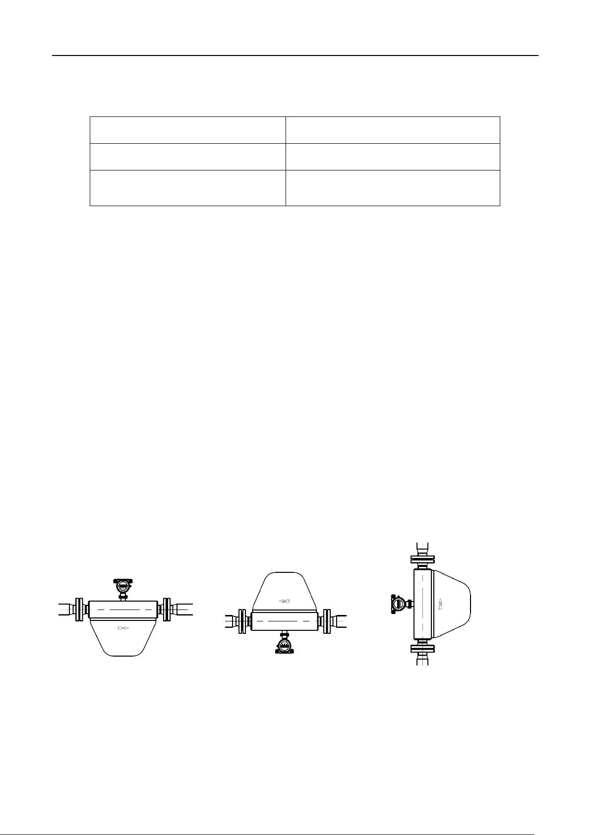
For horizontal installation, the measuring tube should be installed under the pipe when the process
medium is liquid or slurry (shown on Drawing 9) and on top of the pipe when the process medium
is gas (shown on Drawing 10). For vertical installation, the measuring tube would be installed
besides the pipe when the process medium is liquid, slurry or gas (shown on Drawing 11)
Drawing 9 Drawing 10 Drawing 11
17 / 36
Page 18

3.3.2 Flow direction:
There is flow direction arrow that indicates the proper flow direction on the front of the sensor,
install the FMC Coriolis Meter accordingly.
For vertical installation, if the process medium is liquid or slurry, the flow direction should be from
down-to-up; if the process medium is gas, the flow direction can be either down-to-up or up-to-
down. The transmitter can be mounted with 90° rotation according to the requirement of installation.
3.4 Sensor Installation
3.4.1 Basic requirements:
The installation of the FMC Coriolis Meter should be in a straight line.
Meanwhile, do not support the pipeline with FMC Coriolis Meter. (As
shown in Drawing 12)
3.4.2 Installation of the FMC Coriolis Meter 6” or lager:
It is better to support the sensor of FMC Coriolis Meter using rubber
connectors as the buffer.
3.5 Wiring
3.5.1 Basic requirements:
If the sensor of FMC Coriolis Meter is installed integrally with the transmitter, it will be OK that the
power of transmitter is connected. If the sensor of FMC Coriolis Meter is installed separately from
the transmitter, it will be required that the transmitter is connected with sensor through special nine-
core cable. If the FMC Coriolis Meter 6” (DN150mm) or larger is installed, it is required that the
drive-amplifier of sensor is supplied with separate power.
3.5.2 Junction box
If the sensor and the transmitter are installed separately, the sensor and transmitter have been
respectively matched with junction box for connecting the special nine-core cable.
3.5.3 Cable connection
If the sensor and the transmitter are installed separately, signal lines are 9-core cables between
transmitters and mass flow sensors.
18 / 36
Page 19

Line NO.
Line Color
Function
1
brown
The left coil+
2
red
The left coil-
3
orange
The right coil+
4
yellow
The right coil-
5
green
Driving coil+
6
blue
Driving coil-
7
Gray
Temperature+
8
white
Temperature-
9
black
Temperature Compensation
Table 24: cables and functions
Cut off power before connecting cables. The power voltage must match that
indicated in the junction box of the transmitter and the ground wire must be well
grounded to ensure its intrinsic safety performance.
19 / 36
Page 20

3.5.4 Grounding
Both of the sensor and the transmitter have to be grounded correctly, otherwise a measurement
error will occur and the FMC Coriolis Meter may not work. If the pipeline is grounded, the transmitter
can be grounded through the pipeline; if the pipeline is not grounded, the transmitter should be
grounded independently.
3.5.5 Power line wiring
The transmitter can be supplied with 18-36V dc (Standard) or 85-265V ac (Optional). The power
line more than 0.8mm2 is recommended and the maximum length of power line should be 300m.
For FMC Coriolis Meter 6” or larger, a separate driver amplifier is required to be supplied for power.
3.6 Start-up
3.6.1 Zero-point calibration
Zero-point calibration supplies the base point for the flow meter. After the first installation or
reinstallation, Zero-point calibration is required for the FMC Coriolis Meter. Before zero-point
calibration, close the valve downstream of the flow sensor to make sure that no fluid is flowing
through the pipe. The sensor should be filled with process fluid whose temperature change should
not exceed ±10℃. If the flow meter is zeroed when fluids are flowing through, its measurement will
appear much smaller. At that time, stop using the meter or re-zero it before use.
3.6.2 Instrument coefficient
Each FMC Coriolis Meter has its own instrument coefficients, which has been set before delivery
and shown on the calibration report. So the user does not need to set instrument coefficients except
if either the sensor or the transmitter is replaced. All the coefficients that can be found on the
calibration report are also printed on the name plate. Generally, the sensor and the transmitter are
coupled, and the coefficient has been input into the transmitter. The meter can be used without
additional change.
20 / 36
Page 21
Power Supply and Signal Output Wiring
AC (85 to 265) V
Power Consume: Normal 10 W, MAX 15W
DC (18 to 30) V
Power Consume: Normal 10 W, MAX 15W
4.1 Power Wiring
4.1.1 The basic requirement:
The transmitter can be connected to the AC or the DC power.
Table 25
4.1.2 Power Cable
The power cable should be a 2-core cable and 20 gauge minimum.
The maximum length of the power cable is 300m.
Drawing 13: AC Power Wiring
21 / 36
Page 22

Drawing 14: DC Power Wiring
4.2 Current Output Wiring
4~20mA output can be configured to mass flow, volume flow, density or water ratio.
The cable should be 2-core cable and 24 gauge minimum.
The factory default current output is passive current output.
Drawing 15
22 / 36
Page 23

The outer wiring of passive current output is as the figure shows below:
Drawing 16
4.3 Pulse Output Wiring
Active pulse output can be configured to mass flow, volume flow, density or water ratio.
The cable should be 2-core cable and 24 gauge minimum. The maximum length of output line
is 150m.
Drawing 17
23 / 36
Page 24

4.4 RS485 Output Wiring
RS485 output is compatible to RTU mode of MODBUS protocol. The maximum length of output
line is ≤300m.
Drawing 18
24 / 36
Page 25
→
Configuration
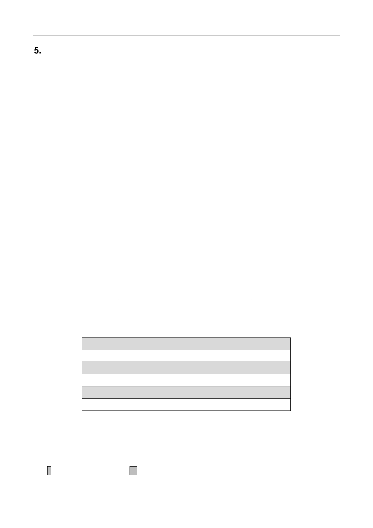
No.
Notes
1
E key: enter
2
→ key: move curse or return
3
↓ key: page down
4
OLED light for working status
5
Two-line LCD
5.1 General
Please use the operation panel of transmitter to set the configuration, such as basic configuration
parameters, zero calibration, cutoff value of low flow and output range of current frequency, etc.
The face plate of the transmitter is shown in Drawing 19.
Drawing 19
5.2 Configuration Parameter
(Note: Default Password: “000000”)
Please review or set the configuration parameters according to the following indications (press
↓ to turn a page and press to move the position of cursor or return):
25 / 36
Page 26

Notice: If you forget your password, you MUST call
an Omega flow engineer to reset it!!!
26 / 36
Page 27

5.3 Calibration
Generally speaking, the FMC Coriolis Meter does not need field calibration because it has been
calibrated before delivery.
Each FMC Coriolis Meter has its own instrumental coefficient, including one flow coefficient and
four density coefficients (high density D1, high period K1, low density D2 and low period K2), which
will be shown in Nameplate of Sensor or Calibration certificate.
The sensor and transmitter are usually delivered as a pair and instrumental coefficient has been
set in the transmitter so the user does not need to change.
5.3.1 Zero Calibration
Zero calibration provides the reference point for the flow meter. It is necessary to conduct the zero
calibration whenever the FMC Coriolis Meter installation is performed.
After installation, the FMC Coriolis Meter should be powered at least 30 minutes for warm-up
and then pass flow through the flow meter until the temperature of FMC Coriolis Meter is
same as working temperature of fluid. Afterward, close the downstream valve, make the fluid
pass through the flow meter under normal temperature, density and pressure and then close the
upstream valve to assure the sensor is full of liquid during the process of zero calibration.
Notice: Each zero calibration lasts 30s and must repeat at least 10 times.
27 / 36
Page 28

K1
New flow calibration factor,
K0
Old flow calibration factor,
M
Total mass flow of Master Meter,
Mt
Total mass flow of Tested Meter.
5.3.2 Flow Calibration
The mass measured by the FMC Coriolis Meter is resulted from the multiplication of detected
signals’ time difference between two circuits and flow calibration factor. If the accuracy is not up to
grade after long-term service, please modify the flow calibration factor according to the following
formula:
K1=K0× [1+ (M-Mt) / Mt] =K0×M/Mt
Note:
28 / 36
Page 29
0.0001
0.001
0.01
0.1
20 200 3000
Pressure Loss(MPa)
Flow(m3/h)
DN15-Pressure Loss Chart
0.01
1
10
100
Pressure Loss
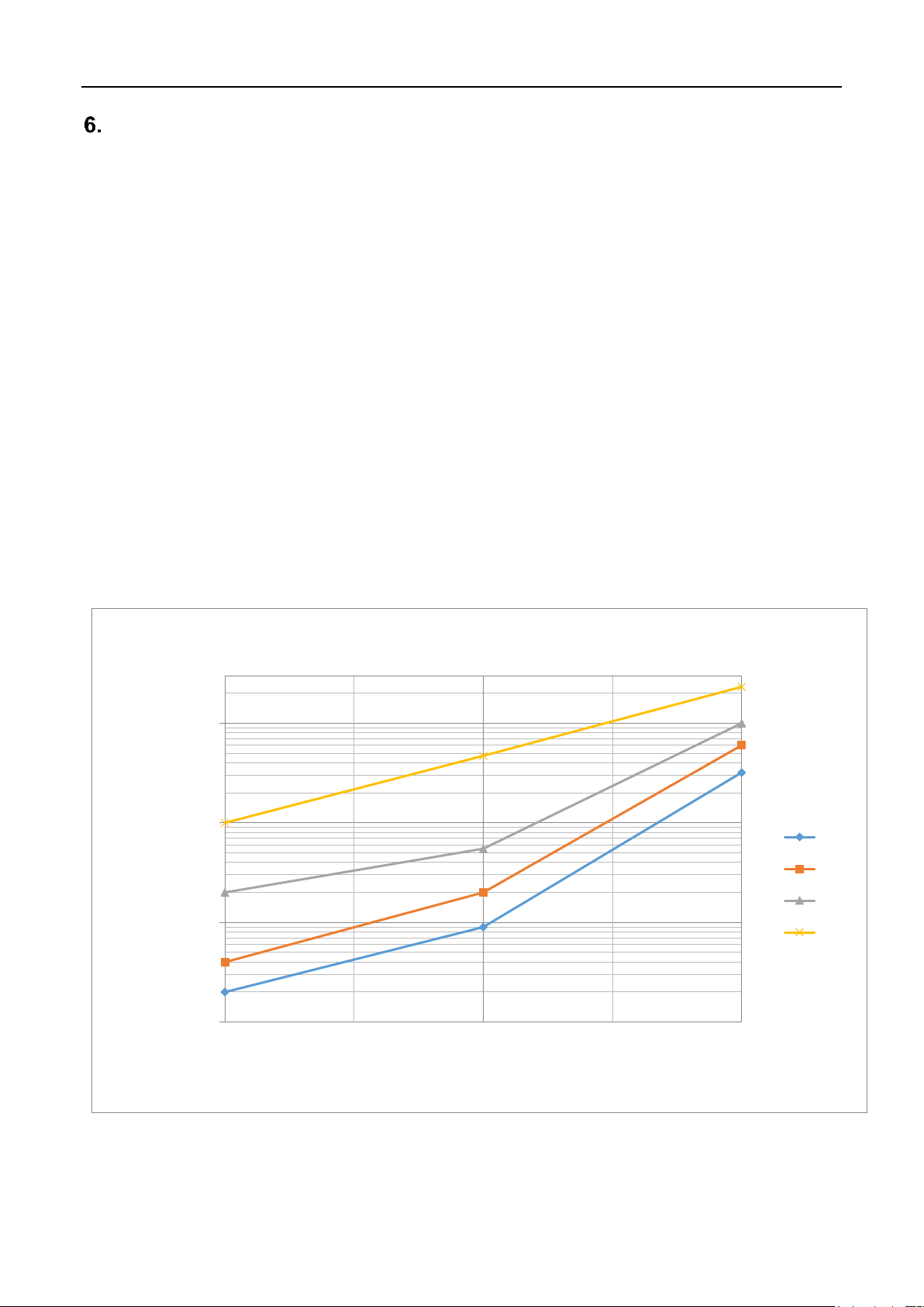
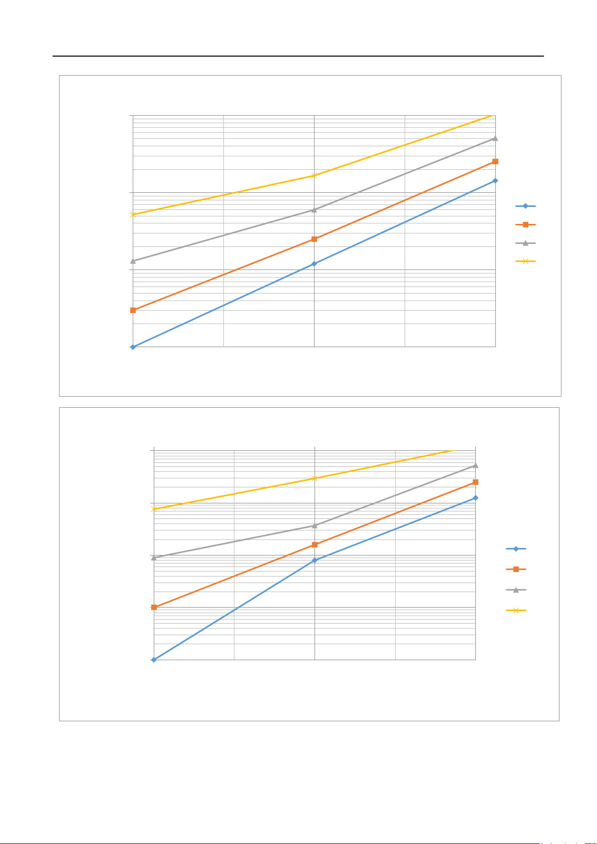
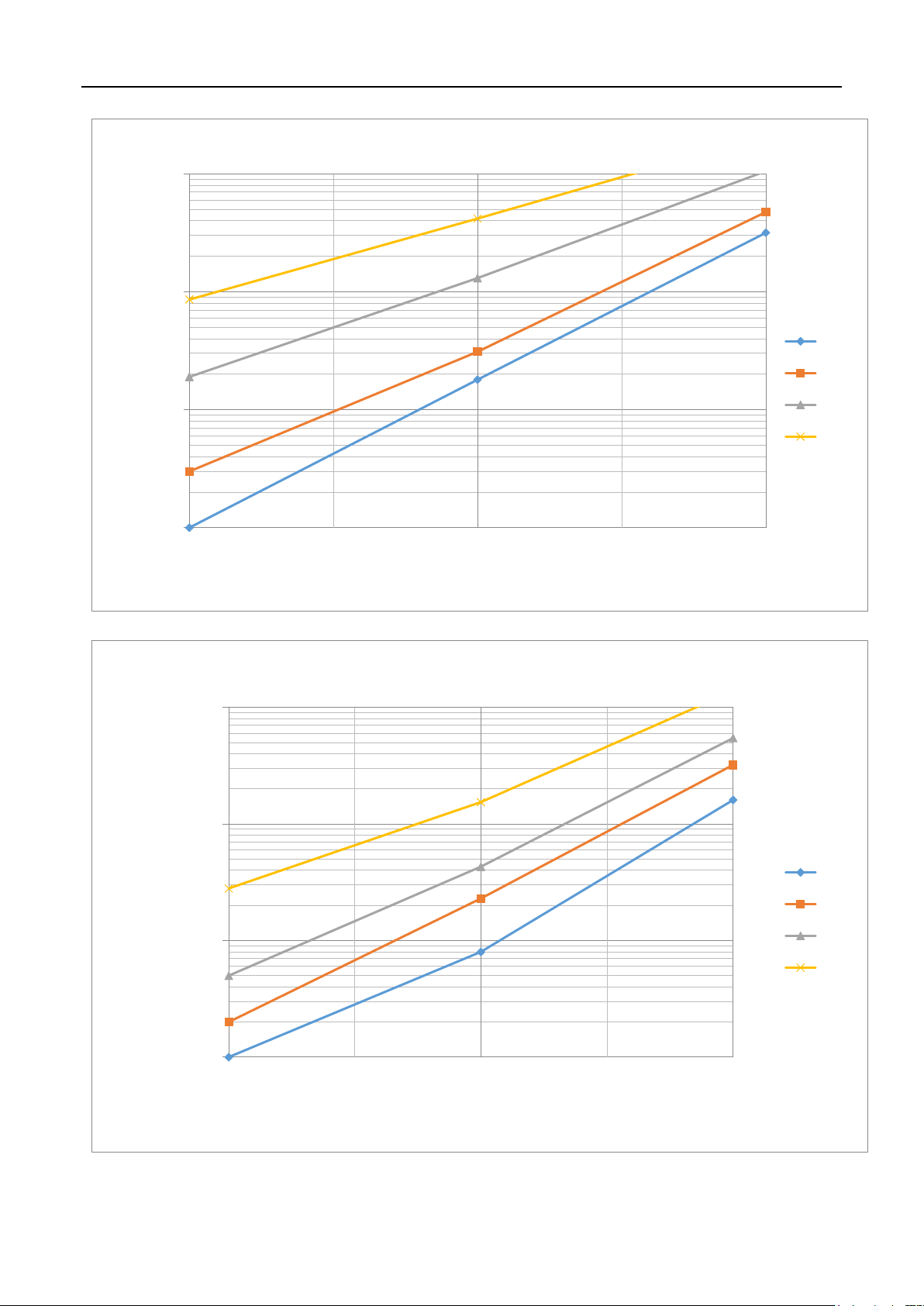
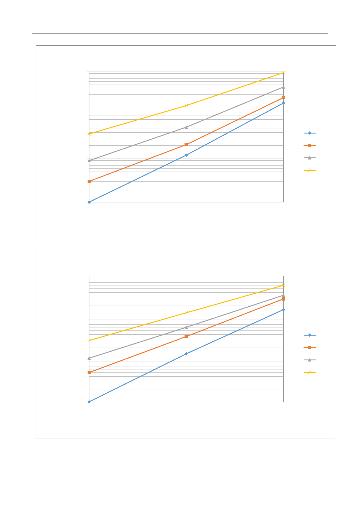
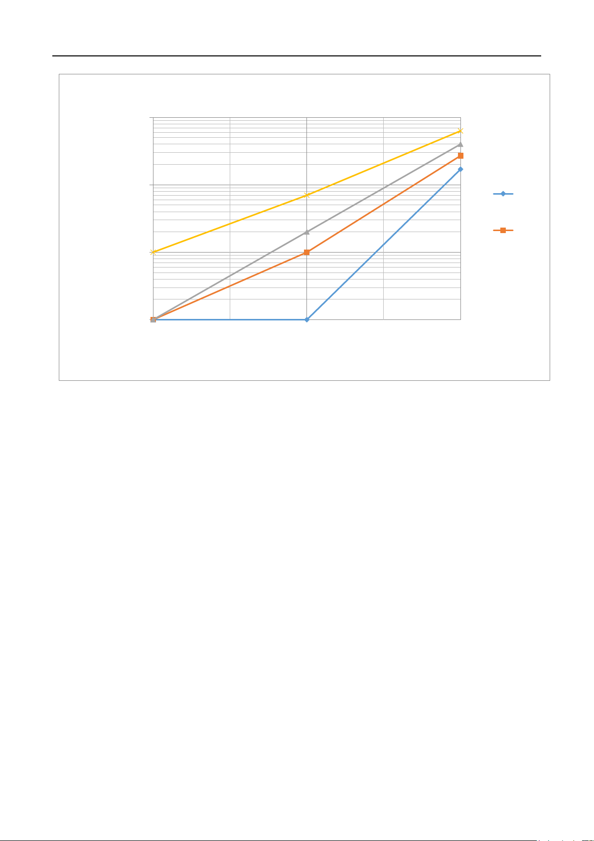
The pressure loss of FMC Coriolis Meter can be checked on the following Pressure Loss Charts
(including pressure loss, flow, and viscosity parameters).
When the viscosity is between two adjacent pressure loss lines, the pressure loss can be calculated
with following formula:
Note:
The mass flow value can be converted to the volume flow value with followed formula:
Volume flow rate = Mass flow rate / Density
Follow is the pressure loss for different size flow meter
29 / 36
Page 30
0.0001
0.001
0.01
0.1
80 800 8000
Pressure Loss(MPa)
Flow(m3/h)
DN25-Pressure Loss Chart
0.01
1
10
100
0.00001
0.0001
0.001
0.01
0.1
240 2400 24000
Pressure Loss(MPa)
Flow(m3/h)
DN40-Pressure Loss Chart
0.01
1
10
100
30 / 36
Page 31
0.0001
0.001
0.01
0.1
500 5000 50000
Pressure Loss(MPa)
Flow(m3/h)
DN50-Pressure Loss Chart
0.01
1
10
100
0.0001
0.001
0.01
0.1
800 8000 120000
Pressure Loss(MPa)
Flow(m3/h)
DN80-Pressure Loss Chart
0.01
1
10
100
31 / 36
Page 32
0.0001
0.001
0.01
0.1
1500 15000 200000
Pressure Loss(MPa)
Flow(m3/h)
DN100-Pressure Loss Chart
0.01
1
10
100
0.0001
0.001
0.01
0.1
5000 50000 500000
Pressure Loss(MPa)
Flow(m3/h)
DN150-Pressure Loss Chart
0.01
1
10
100
32 / 36
Page 33
0.00001
0.0001
0.001
0.01
10000 100000 1000000
Pressure Loss(MPa)
Flow(m3/h)
DN200-Pressure Loss Chart
0.0
1
1
33 / 36
Page 34

OLED condition
Working condition
Green light
Normal Operation
Red light
Error
Trouble Shooting
7.1 Overview
Upon first installation and operation, if there is an abnormal working phenomenon, the user should
determine the causes.
Generally speaking, the causes may one of two kinds: flow meter or application causes. Application
problems are usually complex. Fluctuation measurement error caused by the process or medium
status changes, should be analyzed according to the actual application. This chapter mainly
focuses on the causes and troubleshooting of flow meter system malfunctions.
7.2 Diagnostic Tool
For flow meter fault diagnosis, the user can check the OLED indicator and LCD displays, OLED
lights of different colors and brightness contrast on the panel, which represent the working condition
of flow meter. Meanwhile, LCD displays can show the self-diagnostic alarm information of the
transmitter, which is useful for defining the malfunctions.
In addition, it is necessary to use handheld digital multi-meter when testing the static resistance
values and cables of the sensor.
The proportion of light and dark shown by OLED indicator represents the working condition of the
flow meter.
Table 27
34 / 36
Page 35
7.3 Sensor
Loop
Line color
Sensor port
Normal resistance range
Left coil
Brown, red
1, 2
(60~75)Ω
Right coil
Orange, yellow
3, 4
(60~75)Ω
Drive coil
Blue, green
5, 6
(6~30)Ω
Temperature
Gray, white
7, 8
(75~175)Ω
Temperature
Gray, black
7, 9
(75~175)Ω
When testing a malfunction of the flow meter, first test the coils resistance according to Table 26
and check if their values are within the normal range.
Table 26
7.4 Power and connection
Initial installation of electricity power should be checked to ensure the following:
Choose the correct voltage for power supply, connect the power cable correctly, open insulating
layer of two ends of the cable and connect them firmly;
AC Power cable should not be connected through the same output as the signal cables;
Transmitter should be grounded firmly and the earth resistance should be less than 1 Ω, (use the
copper wire 10 gauge minimum).
35 / 36
Page 36

Explosion-proof (Optional)
ITEM
T3
T4
T5
T6
Working temperature
200℃
135℃
100℃
85℃
Surface temperature
195℃
130℃
95℃
80℃
FMC Coriolis Meter-Model
Explosion-proof Grade
Integrate Type
ExdibⅡCT4~T6(ⅡC contains hydrogen only)
8.1 The explosion-proof grades of FMC Coriolis Meter Table 28
The ambient temperature range is (-40~+55) ℃.
The FMC-5000 Series Coriolis Meter contains the grounding terminal which must be grounded
when put into service.
The user should not change the electric parameters and standard model of explosion-proof
parts in the sensor.
The cable jacket can be divided into two kinds of φ8.5mm and φ12mm according to the inner
hole of cable gasket ring while the outside diameters of cables are respectively φ8mm~φ8.5mm
and φ8.5mm~φ12mm. Please change the cable and gasket ring once they age or wear out.
Do not use in environment that will corrode/erode the aluminum alloy.
Be sure that the maintenance or repair is in a safe place without flammable gaseous.
The relationship between working temperature of medium and maximum surface temperature
of flow meter body are as follows:
Table 29
M-5621/0217
36 / 36
Page 37

WARRANTY/DISCLAIMER
OMEGA ENGINEERING, INC. warrants this unit to be free of defects in materials and workmanship for
a period of
month grace period to the normal
time. This ensures that OMEGA’s customers receive maximum coverage on each product.
If the unit malfunctions, it must be returned to the factory for evaluation. OMEGA’s Customer Service
Department will issue an Authorized Return (AR) number immediately upon phone or written request.
Upon examination by OMEGA, if the unit is found to be defective, it will be repaired or replaced at no
charge. OMEGA’s WARRANTY does not apply to defects resulting from any action of the purchaser,
including but not limited to mishandling, improper interfacing, operation outside of design limits, improper
repair, or unauthorized modification. This WARRANTY is VOID if the unit shows evidence of havin g
been ta m p ered wit h or shows evid e n c e of havi ng been d a maged as a res ult of
exc e ssive c orros ion; or curre nt, heat, mois ture or v ibrat ion; i mprop er s p ec i f i c at i o n ;
misapplication ; mis u se or o ther ope r a t ing c o n d i t ions ou t s ide of O MEG A’s control.
Components in which wear is not warranted, inc lud e but are not limited to contact points, fuses,
and triacs.
OMEGA is pleased to offer suggestions on the use of its various products. However,
OMEGA neither assumes responsibility for any omissions or errors nor assumes
liability for any damages that result from the use of its products in acco
rdance with information provided by OMEGA, either verbal or written. OMEGA
warrants only that the parts manufactured by it will be as specified and free of
defects. OMEGA MAKES NO OTHER WARRANTIES OR REPRESENTATIONS OF ANY
KIND WHATSOEVER, EXPRESS OR IMPLIED, EXCEPT THAT OF TITLE, AND ALL IMPLIED
WARRANTIES INCLUDING ANY WARRANTY OF MERCHANTABILITY AND FITNESS FOR
A PARTICULAR PURPOSE ARE H E R E B Y
DISCLAIMED. LIMITATION OF LIABILITY: The remedies of purchaser set forth herein are
exclusive, and the total liability of OMEGA with respect to this order, whether based
on contract, warranty, negligence, indemnification, strict liability or otherwise, shall not
exceed the purchase price of the component upon which liability is based. In
no event shall OMEGA be liable for consequential, incidental or special damages.
CONDITIONS: Equipment sold by OMEGA is not intended to be used, nor shall it be used: (1) as a
“Basic Component” under 10 CFR 21 (NRC), used in or with any nuclear installation or activity; or (2)
in medical applications or used on humans. Should any Product(s) be used in or with any nuclear
installation or activity, medical application, used on humans, or misused in any way, OMEGA assumes
no responsibility as set forth in our basic WARRANTY / DISCLAIMER language, and, additionally,
purchaser will indemnify OMEGA and hold OMEGA harmless from any liability or damage whatsoever
arising out of the use of the Product(s) in such a manner.
13 months
from date of purchase. OMEGA’s WARRANTY adds an additional one (1)
one (1) year product warranty
to cover handling and shipping
RETURN REQUESTS/INQUIRIES
Direct all warranty and repair requests/inquiries to the OMEGA Customer Service Department.
BEFORE RETURNING ANY PRODUCT(S) TO OMEGA, PURCHASER MUST OBTAIN AN AUTHORIZED
RETURN (AR) NUMBER FROM OMEGA’S CUSTOMER SERVICE DEPARTMENT (IN ORDER TO AVOID
PROCESSING DELAYS). The assigned AR number should then be marked on the outside of the return
package and on any correspondence.
The purchaser is responsible for shipping charges, freight, insurance and proper packaging to prevent
breakage in transit.
FOR
WARRANTY
following information available BEFORE
contacting OMEGA:
1.
Purchase Order number under which the
product was PURCHASED,
2.
Model and serial number of the product under
warranty, and
3.
Repair instructions and/or specific problems
relative to the product.
RETURNS, please have the
FOR NON-WARRANTY REPAIRS, consult OMEGA
For current repair charges. Have the following
information available BEFORE contacting OMEGA:
1.
Purchase Order number to cover the COST
of the repair,
2.
Model and serial number of the product, and
3.
Repair instructions and/or specific problems
relative to the product.
OMEGA’s policy is to make running changes, not model changes, whenever an improvement is
possible. This affords our customers the latest in technology and engineering.
OMEGA is a registered trademark of OMEGA ENGINEERING, INC.
© Copyright 2016 OMEGA ENGINEERING, INC. All rights reserved. This document may not be copied, photocopied,
reproduced, translated, or reduced to any electronic medium or machine-readable form, in whole or in part, without the
prior written consent of OMEGA ENGINEERING, INC.
Page 38
Where Do I Find Everything I Need for
Process Measurement and Control?
OMEGA…Of Course!
Shop online at omega.com
TEMPERATURE
Thermocouple, RTD & Thermistor Probes, Connectors,
Panels & Assemblies
Wire: Thermocouple, RTD & Thermistor
Calibrators & Ice Point References
Recorders, Controllers & Process Monitors
Infrared Pyrometers
PRESSURE, STRAIN AND FORCE
Transducers & Strain Gages
Load Cells & Pressure Gages
Displacement Transducers
Instrumentation & Accessories
FLOW/LEVEL
Rotameters, Gas Mass Flowmeters & Flow Computers
Air Velocity Indicators
Turbine/Paddlewheel Systems
Totalizers & Batch Controllers
SM
pH/CONDUCTIVITY
pH Electrodes, Testers & Accessories
Benchtop/Laboratory Meters
Controllers, Calibrators, Simulators & Pumps
Industrial pH & Conductivity Equipment
DATA ACQUISITION
Communications-Based Acquisition Systems
Data Logging Systems
Wireless Sensors, Transmitters, & Receivers
Signal Conditioners
Data Acquisition Software
HEATERS
Heating Cable
Cartridge & Strip Heaters
Immersion & Band Heaters
Flexible Heaters
Laboratory Heaters
ENVIRONMENTAL
MONITORING AND CONTROL
Metering & Control Instrumentation
Refractometers
Pumps & Tubing
Air, Soil & Water Monitors
Industrial Water & Wastewater Treatment
pH, Conductivity & Dissolved Oxygen Instruments
M5621/0217
 Loading...