

Page 1

Page 2

/-%'!NET¤/NLINE3ERVICE )NTERNETEMAIL
OMEGACOM INFO OMEGACOM
-iÀÛV}Ê ÀÌÊiÀV>\
53! /MEGA%NGINEERING)NC/NE/MEGA$RIVE0/"OX
-"Êää£ÊiÀÌvi`
3TAMFORD#453!
4OLL&REE 4%,
&!8 EMAILINFO OMEGACOM
#ANADA "ERGAR
,AVAL1UEBEC#ANADA(,!
4OLL&REE 4%,
&!8 EMAILINFO OMEGACA
ÀÊi`>ÌiÊÌiVV>ÊÀÊ>««V>ÌÊ>ÃÃÃÌ>Vi\
53!AND#ANADA 3ALES3ERVICE4#/-%'!
#USTOMER3ERVICE"%34
%NGINEERING3ERVICE53!7(%.
-EXICO %N%SPA×OL &!8
INFO OMEGACOMMX EMAILESPANOL OMEGACOM
¤
¤
¤
-iÀÛV}ÊÕÀ«i\
"ENELUX -ANAGEDBYTHE5NITED+INGDOM/FFICE
4OLL&REE 4%,
&!8 EMAILSALES OMEGANL
#ZECH2EPUBLIC &RYSTATSKA
+ARVINÈ#ZECH2EPUBLIC
4OLL&REE 4%,
&!8 EMAILINFO OMEGASHOPCZ
&RANCE -ANAGEDBYTHE5NITED+INGDOM/FFICE
4OLL&REE 4%,
&!8 EMAILSALES OMEGAFR
'ERMANY!USTRIA $AIMLERSTRASSE
$$ECKENPFRONN'ERMANY
4OLL&REE 4%,
&!8 EMAILINFO OMEGADE
5NITED+INGDOM /-%'!%NGINEERING,TD
-"Êää£ÊiÀÌvi`
ÌÊÃÊÌiÊ«VÞÊvÊ"Ê}iiÀ}]ÊV°ÊÌÊV«ÞÊÜÌÊ>ÊÜÀ`Ü`iÊÃ>viÌÞÊ>`ÊÉ
Ài}Õ>ÌÃÊÌ>ÌÊ>««Þ°Ê"ÊÃÊVÃÌ>ÌÞÊ«ÕÀÃÕ}ÊViÀÌvV>ÌÊvÊÌÃÊ«À`ÕVÌÃÊÌÊÌiÊÕÀ«i>Ê iÜ
««À>VÊÀiVÌÛiðÊ"ÊÜÊ>``ÊÌiÊÊ>ÀÊÌÊiÛiÀÞÊ>««À«À>ÌiÊ`iÛViÊÕ«ÊViÀÌvV>Ì°
/iÊvÀ>ÌÊVÌ>i`ÊÊÌÃÊ`VÕiÌÊÃÊLiiÛi`ÊÌÊLiÊVÀÀiVÌ]ÊLÕÌÊ"Ê>VVi«ÌÃÊÊ>LÌÞÊvÀÊ>Þ
iÀÀÀÃÊÌÊVÌ>Ã]Ê>`ÊÀiÃiÀÛiÃÊÌiÊÀ}ÌÊÌÊ>ÌiÀÊëiVvV>ÌÃÊÜÌÕÌÊÌVi°
7, \Ê/iÃiÊ«À`ÕVÌÃÊ>ÀiÊÌÊ`iÃ}i`ÊvÀÊÕÃiÊ]Ê>`ÊÃÕ`ÊÌÊLiÊÕÃi`ÊvÀ]ÊÕ>Ê>««V>Ìð
/NE/MEGA$RIVE2IVER"END4ECHNOLOGY#ENTRE.ORTHBANK
)RLAM-ANCHESTER-"$%NGLAND
4OLL&REE 4%,
&!8 EMAILSALES OMEGACOUK
Page 3

The Omega product you have just received is of the highest quality available, offering superior performance,
reliability and value to the user. It is designed with the ever changing process conditions, accuracy requirement s
and hostile process environments in mind to provide you with a lifetime of dependable service.
We recommend that you read this manual in its entirety. Should you require any additional information concerning
Omega products and services, please contact your local Omega Engineering office listed on the inside front cover
of this manual or visit www.Omega.com.
Page 4

THIS PAGE WAS
INTENTIONALLY
LEFT BLANK
Page 5

FMA-7400/7500 Series Devices - RS485
Paragraph Page
Number Number
Section 1 Introduction
1-1 Introduction ................................................................................................................................1-1
Section 2 Device Configuration and Wiring
2-1 Device Configuration ..................................................................................................................2-1
2-2 Wiring.........................................................................................................................................2-1
Section 3 Message Protocol Structure
3-1 Message Protocol Structure........................................................................................................ 3-1
3-2 Addressing Concept ...................................................................................................................3-1
3-3 Character Coding.......................................................................................................................3-1
3-4 Message Format .........................................................................................................................3-2
3-4-1 Message Structure............................................................................................................3-2
3-4-2 Preamble Characters ........................................................................................................3-2
3-4-3 Start Character .................................................................................................................3-3
3-4-4 Address Characters ..........................................................................................................3-3
3-4-5 Command Character.........................................................................................................3-5
3-4-6 Byte Count Character .......................................................................................................3-5
3-4-7 St atus Characters .............................................................................................................3-5
3-4-8 Data Characters ...............................................................................................................3-6
3-4-8-1 8-Bit Unsigned Integer Format.................................................................................... 3-6
3-4-8-2 24-Bit Unsigned Integer Format..................................................................................3-7
3-4-8-3 IEEE 754 Floating Point Format .................................................................................3-7
3-4-8-4 ASCII Data Format .....................................................................................................3-7
3-4-8-5 Packed-ASCII (6-Bit ASCII) Data Format ..................................................................3-7
3-4-8-6 Checksum Characters................................................................................................ 3-8
Contents
Section 4 Master/Slave Communications
4-1 Master/Slave Communications ....................................................................................................4-1
4-1-1 RS485 Line Handling ........................................................................................................4-1
4-2 Establishing Communications with a Device ...............................................................................4-2
4-2-1 Example of Using Command #11 ......................................................................................4-4
4-3 Alarm Configuration and Monitoring ...........................................................................................4-6
4-4 Error Handling ............................................................................................................................4-6
4-5 Examples ....................................................................................................................................4-7
4-5-1 Reading Flow Rate ............................................................................................................4-7
4-5-2 Sending the Setpoint ......................................................................................................... 4-8
Section 5 General T
5-1 Referenced Documents ..............................................................................................................5-1
5-2 Unit Conversions ........................................................................................................................5-1
5-2-1 Flow Rate Conversions...................................................................................................... 5-1
5-2-2 T emperature Conversions..................................................................................................5-2
ransmitter Information
i
Page 6

Contents
FMA-7400/7500 Series Devices - RS485
Paragraph Page
Number Number
Section 6 Universal Command Specifications
6-1 Command #0 Read Unique Identifier..........................................................................................6-1
6-1-1 Command #0 Specific Response Codes........................................................................... 6-2
6-2 Command #1 Read Primary Variable ......................................................................................... 6-2
6-2-1 Command #1 Specific Response Codes........................................................................... 6-3
6-3 Command #2 Read Primary V ariable Current and Percentage of Rate......................................6-3
6-3-1 Command #2 Specific Response Codes........................................................................... 6-3
6-4 Command #3 Read Current and all Dynamic Variables..............................................................6-4
6-4-1 Command #3 Specific Response Codes........................................................................... 6-5
6-5 Command #6 Write Polling Address...........................................................................................6-5
6-5-1 Command #6 Specific Response Codes........................................................................... 6-6
6-6 Command #1 1 Read Unique Identifier Associated with Tag........................................................6-6
6-6-1 Command #1 1 S pecific Response Codes .........................................................................6-7
6-7 Command #12 Read Message....................................................................................................6-8
6-7-1 Command #12 Specific Response Codes.........................................................................6-8
6-8 Command #13 Read Tag, Descriptor , Date ................................................................................6-9
6-8-1 Command #13 Specific Response Codes.........................................................................6-9
6-9 Command #14 Read Primary V ariable Sensor Information .......................................................6-10
6-9-1 Command #14 Specific Response Codes........................................................................6-10
6-10 Command #15 Read Output Information....................................................................................6-11
6-10-1 Command #15 Specific Response Codes......................................................................6-12
6-1 1 Command #16 Read Final Assembly Number............................................................................6-12
6-1 1-1 Command #16 S pecific Response Codes ......................................................................6-12
6-12 Command #17 Write Message .................................................................................................. 6-13
6-12-1 Command #17 Specific Response Codes......................................................................6-13
6-13 Command #18 Write Tag, Descriptor, Date ...............................................................................6-14
6-13-1 Command #18 Specific Response Codes......................................................................6-15
6-14 Command #19 Write Final Assembly Number ...........................................................................6-15
6-14-1 Command #19 Specific Response Codes......................................................................6-15
Section 7 Common Practice Command Specifications
7
-1 Command #37 Set Primary V ariable Lower Range Value...........................................................7-1
7-1-1 Command #37 Specific Response Codes.........................................................................7-1
7-2 Command #38 Reset Configuration Changed Flag.....................................................................7-1
7-2-1 Command #38 Specific Response Codes.........................................................................7-2
7-3 Command #39 EEPROM Control................................................................................................ 7-2
7-4 Command #42 Perform Master Reset.........................................................................................7-3
7-5 Command #48 Read Additional T ransmitter Status ..................................................................... 7-3
7-5-1 Command #48 Specific Response Codes.........................................................................7-3
7-6 Command #50 Read Dynamic V ariable Assignments.................................................................7-4
7-6-1 Command #50 Specific Response Codes.........................................................................7-4
7-7 Command #59 Write Number of Response Preambles ..............................................................7-5
7-7-1 Command #59 Specific Response Codes.........................................................................7-5
7-8 Command #66 Enter/Exit Fixed Analog Output Mode..................................................................7-6
7-8-1 Command #66 Specific Response Codes.........................................................................7-7
ii
Page 7

FMA-7400/7500 Series Devices - RS485
Paragraph Page
Number Number
7-9 Command #67 Trim Analog Output Zero.....................................................................................7-8
7-9-1 Command #67 Specific Response Codes.........................................................................7-9
7-10 Command #68 T rim Analog Output Span..................................................................................7-10
7-10-1 Command #68 Specific Response Codes..................................................................... 7-11
7-1 1 Command #122 Write Device Indentification Number (Non-Public)..........................................7-12
7-12 Command #123 Select Baud Rate ............................................................................................7-13
Section 8 Transmitter S pecific Command Specifications
8-1 Command #128 Enter/Exit Write Protect Mode (Non-Public) ....................................................8-1
8-8-1 Command #128 Specific Response Codes ......................................................................8-1
8-2 Command #131 Read Serial Number .........................................................................................8-2
8-2-1 Command #131 Specific Response Codes....................................................................... 8-2
8-3 Command #132 Read Model Number .........................................................................................8-3
8-2-1 Command #132 Specific Response Codes....................................................................... 8-3
8-4 Command #134 Read Software Revisions ..................................................................................8-4
8-4-1 Command #134 Specific Response Codes....................................................................... 8-4
8-5 Command #150 Read Process Gas T ype...................................................................................8-5
8-5-1 Command #150 Specific Response Codes....................................................................... 8-5
8-6 Command #151 Read Gas Density , Flow Reference and Flow range.........................................8-6
8-6-1 Command #151 Specific Response Codes....................................................................... 8-7
8-7 Command #152 Read Full Scale Flow Range .............................................................................8-8
8-8 Command #190 Read Standard Temperature and Pressure .......................................................8-9
8-8-1 Command #190 Specific Response Codes....................................................................... 8-9
8-9 Command #191 Read Operational Settings ...............................................................................8-10
8-9-1 Command #191 Specific Response Codes...................................................................... 8-11
8-10 Command #193 Read Operational Settings ...............................................................................8-12
8-10-1 Command #193 Specific Response Codes....................................................................8-12
8-1 1 Command #195 Select Gas Calibration ..................................................................................... 8-12
8-1 1-1 Command #195 S pecific Response Codes ....................................................................8-13
8-12 Command #196 Select Flow Unit ...............................................................................................8-13
8-12-1 Command #196 Specific Response Codes....................................................................8-14
8-13 Command #197 Select Temperature Unit................................................................................... 8-14
8-13-1 Command #197 Specific Response Codes
8-14 Command #215 Read Setpoint Settings ....................................................................................8-16
8-14-1 Command #215 Specific Response Codes....................................................................8-16
8-15 Command #216 Select Setpoint Source ....................................................................................8-17
8-15-1 Command #216 Specific Response Codes....................................................................8-17
8-16 Command #218 Select Softstart ................................................................................................8-18
8-16-1 Command #218 Specific Response Codes....................................................................8-19
8-17 Command #219 Write Linear Softstart Ramp Value ..................................................................8-19
8-17-1 Command #219 Specific Response Codes....................................................................8-20
8-18 Command #220 Read PID Controller Values.............................................................................8-20
8-18-1 Command #220 Specific Response Codes....................................................................8-20
8-19 Command #221 Write PID Controller V alues.............................................................................8-21
8-19-1 Command #221 Specific Response Codes....................................................................8-22
8-20 Command #222 Read V alve Range and Valve Offset.................................................................8-22
....................................................................8-15
Contents
iii
Page 8

Contents
FMA-7400/7500 Series Devices - RS485
Paragraph Page
Number Number
8-20-1 Command #222 Specific Response Codes.................................................................... 8-22
8-21 Command #223 Write V alve Range and V alve Offset ................................................................8-23
8-21-1 Command #223 Specific Response Codes.................................................................... 8-23
8-22 Command #226 T rim Setpoint Input...........................................................................................8-24
8-22-1 Command #226 Specific Response Codes.................................................................... 8-24
8-23 Command #230 Get V alve Override S tatus ................................................................................8-25
8-23-1 Command #230 Specific Response Codes.................................................................... 8-25
8-24 Command #231 Set V alve Override Status ................................................................................ 8-26
8-24-1 Command #231 Specific Response Codes.................................................................... 8-26
8-25 Command #235 Read Setpoint in % and Selected Units ........................................................... 8-27
8-25-1 Command #235 Specific Response Codes.................................................................... 8-27
8-26 Command #236 Write Setpoint in % or Selected Units .............................................................8-28
8-26-1 Command #236 Specific Response Codes.................................................................... 8-29
8-27 Command #237 Read V alve Control V alue ................................................................................ 8-29
8-27-1 Command #237 Specific Response Codes.................................................................... 8-29
8-28 Command #240 Read Totalizer Status ....................................................................................... 8-30
8-28-1 Command #240 Specific Response Codes.................................................................... 8-30
8-29 Command #241 Set Totalizer Control.........................................................................................8-31
8-29-1 Command #241 Specific Response Codes.................................................................... 8-31
8-30 Command #242 Read Totalizer Value and Unit ..........................................................................8-31
8-30-1 Command #242 Specific Response Codes.................................................................... 8-32
8-31 Command #245 Read Alarm Enable Setting ..............................................................................8-32
8-31-1 Command #245 Specific Response Codes.................................................................... 8-32
8-32 Command #246 Write Alarm Enable Setting..............................................................................8-33
8-32-1 Command #246 Specific Response Codes.................................................................... 8-32
8-33 Command #247 Read High/Low Flow Alarm ..............................................................................8-33
8-33-1 Command #247 Specific Response Codes.................................................................... 8-34
8-34 Command #248 Write High/Low Flow Alarm.............................................................................. 8-34
8-34-1 Command #248 Specific Response Codes.................................................................... 8-35
8-35 Command #250 Change User Password................................................................................... 8-35
8-35-1 Command #250 Specific Response Codes.................................................................... 8-35
Section 9 Transmitter Specific T ables
9-1 Transmitter S pecific T ables .........................................................................................................9-1
9-2 Device T ype Codes ....................................................................................................................9-1
9-3 Flow Rate Unit and Reference Codes.........................................................................................9-1
9-4 Density Unit Codes.....................................................................................................................9-2
9-5 Temperature Unit Codes .............................................................................................................9-2
9-6 Pressure Unit and Reference Codes..........................................................................................9-3
9-7 Write Protect Codes...................................................................................................................9-3
9-8 Physical Signalling Codes ..........................................................................................................9-3
9-9 Transmitter V ariable Codes.........................................................................................................9-4
iv
Page 9

Contents
FMA-7400/7500 Series Devices - RS485
Paragraph Page
Number Number
9-10 Flag Assignments........................................................................................................................9-4
9-1 1 Analog Output Selection Codes ..................................................................................................9-4
9-12 Setpoint Source Selection Codes...............................................................................................9-5
9-13 Softstart Selection Codes ........................................................................................................... 9-5
9-14 V alve Override Codes.................................................................................................................9-6
9-15 T otalizer Command/S tatus Codes ...............................................................................................9-6
9-16 Totalizer Unit Codes....................................................................................................................9-6
9-17 Analog Output Unit Codes...........................................................................................................9-6
9-18 Additional Device Status and Masking ........................................................................................9-7
Warranty, Local Sales/Service Contact Information....................................................................... Back Cover
Figure Page
Number Number
2-1 RS485 Multidrop Interconnection DMF/C and PC ......................................................................2-2
3-1 Single Character Bit Sequence ..................................................................................................3-2
3-2 HART Message Structure ........................................................................................................... 3-2
3-3 Start Character Settings .............................................................................................................3-3
3-4 Short Frame Address Character.................................................................................................3-4
3-5 Long Frame Address Character .................................................................................................3-4
3-6 Packed-ASCII Construction .......................................................................................................3-7
4-1 Typical Message Exchange Using RS485 Communications .......................................................4-1
4-2 Command #1 1 Response to Long Frame Address......................................................................4-3
4-3 Command #11 Master Request...................................................................................................4-4
4-4 Command #11 Response Message.............................................................................................4-5
4-5 Extracting the Long Address.......................................................................................................4-5
4-6 Reading Flow Rate Example .......................................................................................................4-8
4-7 Writing Setpoint Example ...........................................................................................................4-9
Table Page
Number Number
1-1 Universal Commands ..................................................................................................................1-2
1-2 Common Practice Commands ....................................................................................................1-2
1-3 Transmitter Specific Commands .................................................................................................1-3
2-1 D-Connector Communication Pins .............................................................................................2-1
3-1 St art Character Codings (Hexadecimal) .....................................................................................3-3
3-2 Status Byte Coding.....................................................................................................................3-6
3-3 Packed-ASCII Codes .................................................................................................................3-8
4-1 Converting T ag Name to Packed-ASCII...................................................................................... 4-4
v
Page 10

Contents
FMA-7400/7500 Series Devices - RS485
THIS PAGE WAS
INTENTIONALLY
LEFT BLANK
vi
Page 11

1-1 Introduction
Section 1 Introduction
FMA-7400/7500 Series Devices - RS485
The Digital Communication RS485 Protocol provides a reliable, transaction
oriented service between a master device, such as a Personal Computer,
and one or more RS485 Protocol compatible Mass Flow Meters and
Controllers. The protocol is designed to allow a centralized controller to
acquire measurement data from a Mass Flow device and, in case of Mass
Flow Controllers, send setpoint values.
The FMA-7400/7500 Series RS485 Protocol devices support digital
communications as defined by this manual. This protocol is based on the
®
HART
RS485 Protocol devices support all the Universal Commands and many of
the Common Practice commands as defined by the HCF . However ,
conformance to the HCF specifications is neither claimed nor implied.
The only physical layer supported by the FMA-7400/7500 Series devices is
RS485 (see Section 2). The HART Communication Foundation FSK
physical layer (Bell-202 modem) is NOT supported by the FMA-7400/7500
devices. Therefore, the commonly available HART “Hand Held
Configurators” are NOT compatible with FMA-7400/7500 Series devices.
Communication Foundation (HCF) protocol. FMA-7400/7500 Series
This document is intended to give a user the means to implement the
protocol structure into his own control system in order to establish
communication between the control system and the FMA-7400/7500 Series
RS485 devices. It does not cover the non-communication functionality of
the FMA-7400/7500 Series Mass Flow Meters and Controllers. For this
description please refer to Installation and Operation Manual for your
specific device.
The remaining sections of this document are summarized below:
· Section 2 – Device Configuration and Wiring defines how to properly
configure and wire FMA-7400/7500 Series RS485 Protocol devices for
digital communications.
· Section 3 – Message Protocol Structure describes the HART message
protocol.
· Section 4 – Master/Slave Communications describes the
requirements of the Master in the HART protocol.
· Section 5 – General Transmitter Information defines transmitter
specific information such as communication response times and units
conversions.
· Section 6 – Universal Commands defines the message formats for all
supported universal commands.
· Section 7 – Common Practice Commands defines the message
formats for all supported common practice commands.
· Section 8 – Transmitter Specific Commands defines the message
formats for all supported transmitter specific commands.
· Section 9 – Transmitter Specific Tables defines the meanings of
various codes utilized by individual commands.
1-1
Page 12

Section 1 Introduction
FMA-7400/7500 Series Devices - RS485
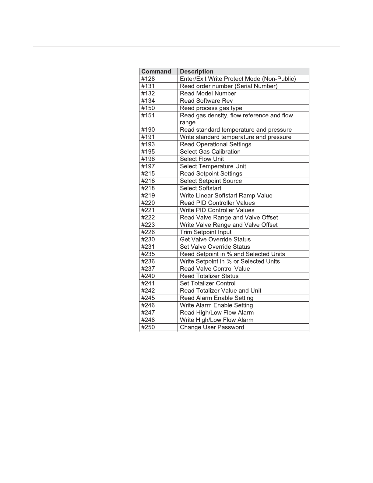
T ables 1-1 through 1-3 provide a summary of RS485 commands available in
the FMA-7400/7500 Series RS485 Protocol devices. This manual provides
details that apply specifically to the FMA-7400/7500 Series RS485
products:
T able 1-1 Universal Commands
Command Description
#0 Read Unique Identifier
#1 Read Primary Variable
#2 Read Primary Variable Current and Percent Range (Supported)
#3 Read Current and all Dynamic Variables
#6 Write Polling Address
#11 Read Unique Identifier associated with Tag
#12 Read Message
#13 Read tag, Descriptor, Date
#14 Read Primary Variable Sensor Information
#15 Read Output Information
#16 Read Final Assembly Number
#17 Write Message
#18 Write Tag, Descriptor, Date
#19 Write Final Assembly Number
(Primary flow and secondary temperature variable supported)
Table 1-2 Common Practice Commands
Command Description
#37 Set Primary Variable Lower Rang e Val ue (Zero)
#38 Reset Configuration Changed Flag
#39 EEPROM control
#42 Perform master reset
#48 Read Additio nal Transmitter Status
#50 Read dynam i c var iable assignment s
#59 Write Num ber of Response Preambles
#66 Enter/Exit Fixed Analog Output M ode
#67 Trim Analog Output Zero
#68 Trim Analog Output Span
#122 Write device id ent if i cat i on number (NON-P UB LIC)
#123 Select Baud Rate
1-2
Page 13
FMA-7400/7500 Series Devices - RS485
T able 1-3 T ransmitter Specific Commands
Section 1 Introduction
1-3
Page 14

Section 1 Introduction
FMA-7400/7500 Series Devices - RS485
THIS PAGE WAS
INTENTIONALLY
LEFT BLANK
1-4
Page 15
2 Device Configuration and Wiring
2-1 Device Configuration
2-2 Wiring
Section 2 Device Configuration
and Wiring
FMA-7400/7500 Series Devices - RS485
The RS485 communications interface is standard on all FMA-7400/7500
Series devices. No hardware configuration is required.
All devices are shipped with the communication data rate set to 19200
baud unless otherwise specified when ordering the device.
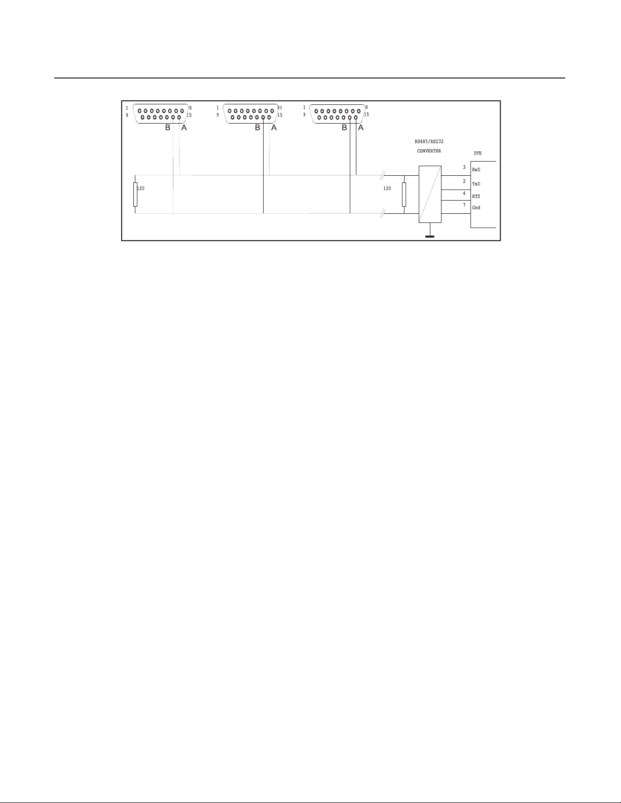
The RS485 communications interface is a multidrop connection making it
possible to connect up to 32 devices to a computer on a single multidrop
line as shown Figure 2-1. Most Computers are NOT equipped with RS485
ports. In order to connect an RS485 to a computer , you will need an
RS485 to RS232C converter. Figure 2-1 shows the connection of three
FMA-7400/7500 Series devices via an RS485 bus utilizing an RS485 to
RS232C converter to the RS232 serial port of a typical computer. The
RS485 bus requires two matching resistors of 120 Ohm, one at the end of
the bus and one at the beginning, near the converter. Note that a control
line from the PC to the converter is necessary to control the data direction
of the RS485 buffers. The RTS (“Request To Send”) line is shown in Figure
2-1 because this line is used to control data direction in many of the
commercially available converters. The actual line used depends on the
converter selected.
T able 2-1 - D-Connector Communication Pins
D-Connector Pin Number RS485
Pin #14 B (inverted driver side)
Pin #15 A (non-inverted driver side)
2-1
Page 16
Section 2 Device Configuration
and Wiring
FMA-7400/7500 Series Devices - RS485
Figure 2-1 - RS485 Multidrop Interconnection DMFM/C and PC
2-2
Page 17

3-1 Message Protocol Structure
3-2 Addressing Concept
Section 3 Message Protocol Structure
FMA-7400/7500 Series Devices - RS485
HART is a “master-slave” protocol: each message transaction is originated
by the master (central) station, whereas the slave (field) device only replies
when it receives a command message addressed to it. The reply from the
slave device will acknowledge that the command has been received and it
may contain the data requested by the master.
FMA-7400/7500 Series RS485 devices do not guarantee the timing
required to support multiple masters communicating simultaneously to slave
devices as defined by the HART Communications Foundation.
FMA-7400/7500 Series RS485 devices do not support Burst Mode.
HART utilizes two possible addressing modes: short frame addressing and
long frame addressing. The short frame addressing uses a one byte
address of which the least significant nibble (four bits) is used to indicate
the slave address. Because slave address 0 is reserved as a broadcast
address, this provides the possibility to attach up to 15 different field
devices and one master device on one multidrop bus. The long frame
addressing mode uses 5 bytes (40 bits) as an address of which 38 bits are
used to indicate the slave device. The slave address is built up from the
manufacturer code (1 byte), the device type code (1 byte) and a device
identification number (3 bytes). Details on addressing are explained in
Section 3-4-4.
3-3 Character Coding
HART messages are coded as a series of 8-bit characters or bytes. These
are transmitted serially , using a conventional UART (Universal
Asynchronous Receiver/ Transmitter). As in normal RS232C and other
asynchronous communication links, a start bit, a parity bit and a stop bit
are added to each byte. These allow the receiving UART to identify the
start of each character and to detect bit errors due to electrical noise or
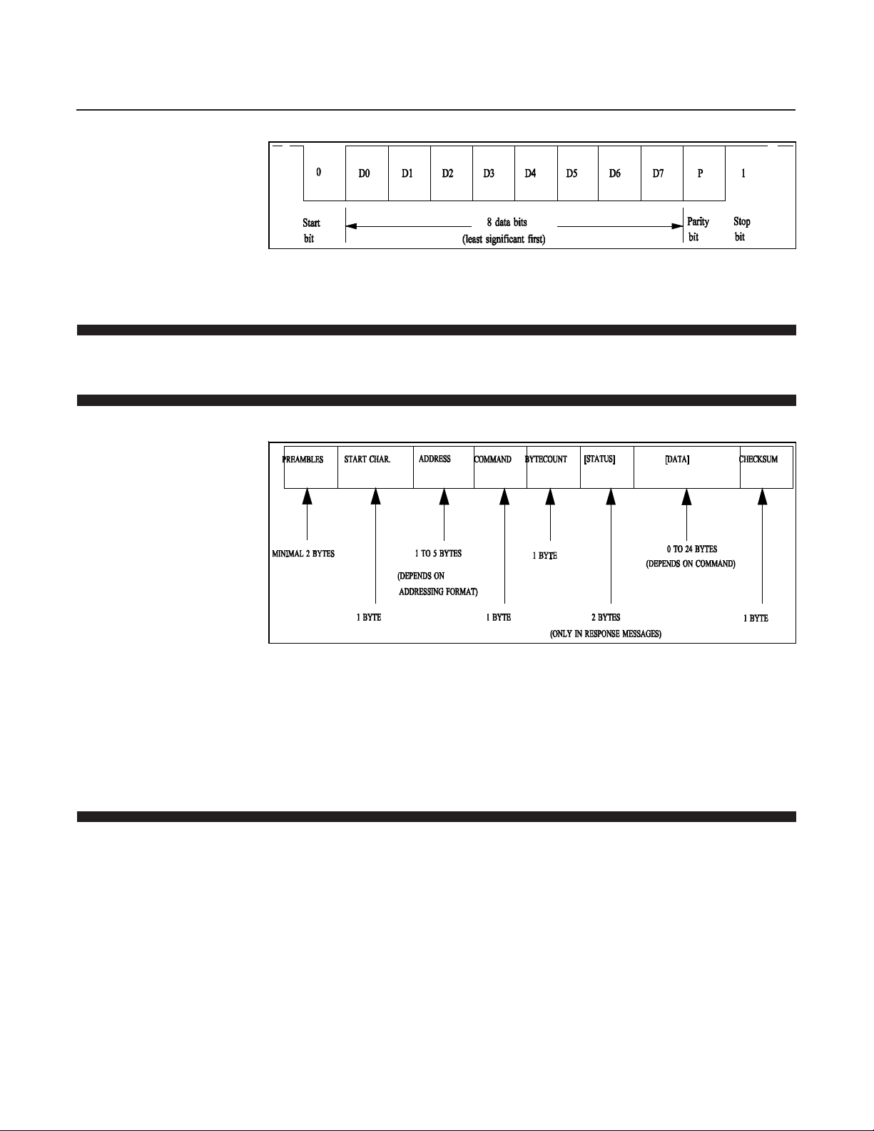
other interference. A HART character is built up from:
1 Start bit - 0 bit
8 Databits
1 Odd parity bit
1 Stop bit - 1 bit
This sequence is summarized in Figure 3-1. Since HART is an
asynchronous protocol, successive characters may be separated by idle
periods (logical 1 level), but the idle period must not exceed 1 character
time.
3-1
Page 18
Section 3 Message Protocol Structure
FMA-7400/7500 Series Devices - RS485
Figure 3-1 Single Character Bit Sequence
3-4 Message Format
3-4-1 Message Structure
HART specifies a message structure which is given in Figure 3-2 below .
3-4-2 Preamble Characters
Figure 3-2 HART Message Structure
This structure is used for both the request (master to slave) and the
response (slave to master) messages. The status part and the dat a part
are shown in square brackets, because their occurrence in the message
depends on the type of message (response or request message) and the
command number. The individual items are explained below.
Every message, whether from a master or a slave device, is preceded by a
specified number of hexadecimal FF characters (databyte with all 1’s).
These characters, called preamble characters, are used in the messagedetect pattern together with the start character . The preamble characters
are used to synchronize the field device. The FMA-7400/7500 Series
RS485 devices require at least 2 preamble characters in order to be able to
proceed in the message detection with the start of message character .
Note that due to potential losses due to RS232 to RS485 converters, a
master should send a minimum of 5 preamble characters in order to
guarantee that slave device receives the required 2 preamble characters.
3-2
Page 19
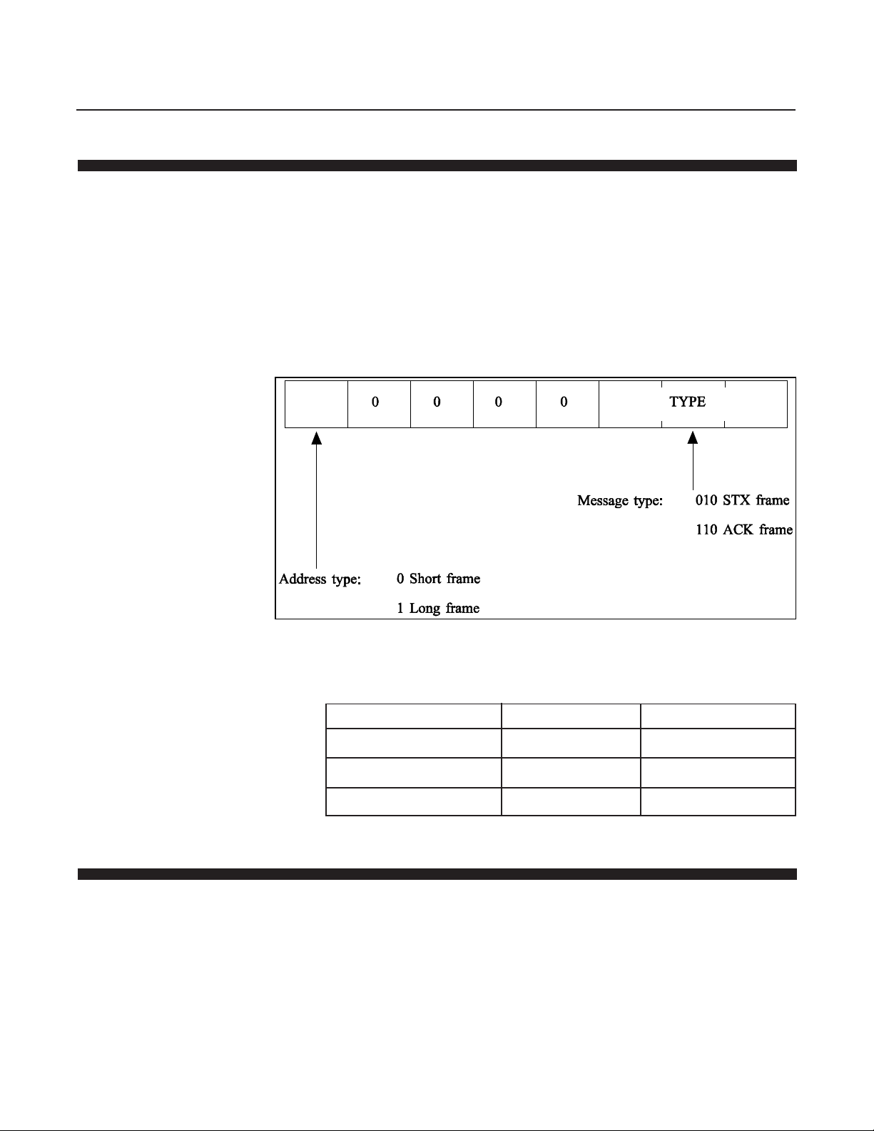
3-4-3 Start Character
Section 3 Message Protocol Structure
FMA-7400/7500 Series Devices - RS485
The start character or delimiter is a one byte code used to detect the type
of frame (type of message) being transmitted and the type of addressing
being used. The most significant bit indicates the addressing mode used: 0
for short frame and 1 for long frame addressing, whereas the three least
significant bits indicate the frame type of the message: 010 indicates a
Start-Of-Text character and 110 indicates an Acknowledge character. The
Start-Of-Text character is used to indicate a message from the master to a
slave device whereas the Acknowledge character is used to indicate the
response messages from slave devices to the master. The rest of the bits
in the character are all zeros. See Figure 3-3 and Table 3-1 below.
3-4-4 Address Characters
Figure 3-3 Start Character Settings
Table 3-1 Start Character Codings (Hexadecimal)
Short frame Long frame
Master to slave (STX) 02 82
Slave to master (ACK) 06 86
Address field length 1 byte 5 bytes
The address field contains both the master and the field device addresses
for the message. These may be contained in a single byte (short frame
format) or in five bytes (long frame format). In either format, the most
significant bit is usually the single-bit address of the master device taking
part in the message transaction (either sending a command or receiving a
reply from a slave device). Since only two masters are allowed only one bit
is needed for the master address. This bit will be 1 if it indicates the
primary master system, and 0 if it indicates the secondary master system.
The rest of the address field is determined by the frame format.
3-3
Page 20
Section 3 Message Protocol Structure
Device
Type
Byte 0
6 Least Significant Bits of
Manufacture ID
1 = Slave in Burst Mode
1 = Primary Master
0 = Secondary Master
Byte 4
Device Identifier
FMA-7400/7500 Series Devices - RS485
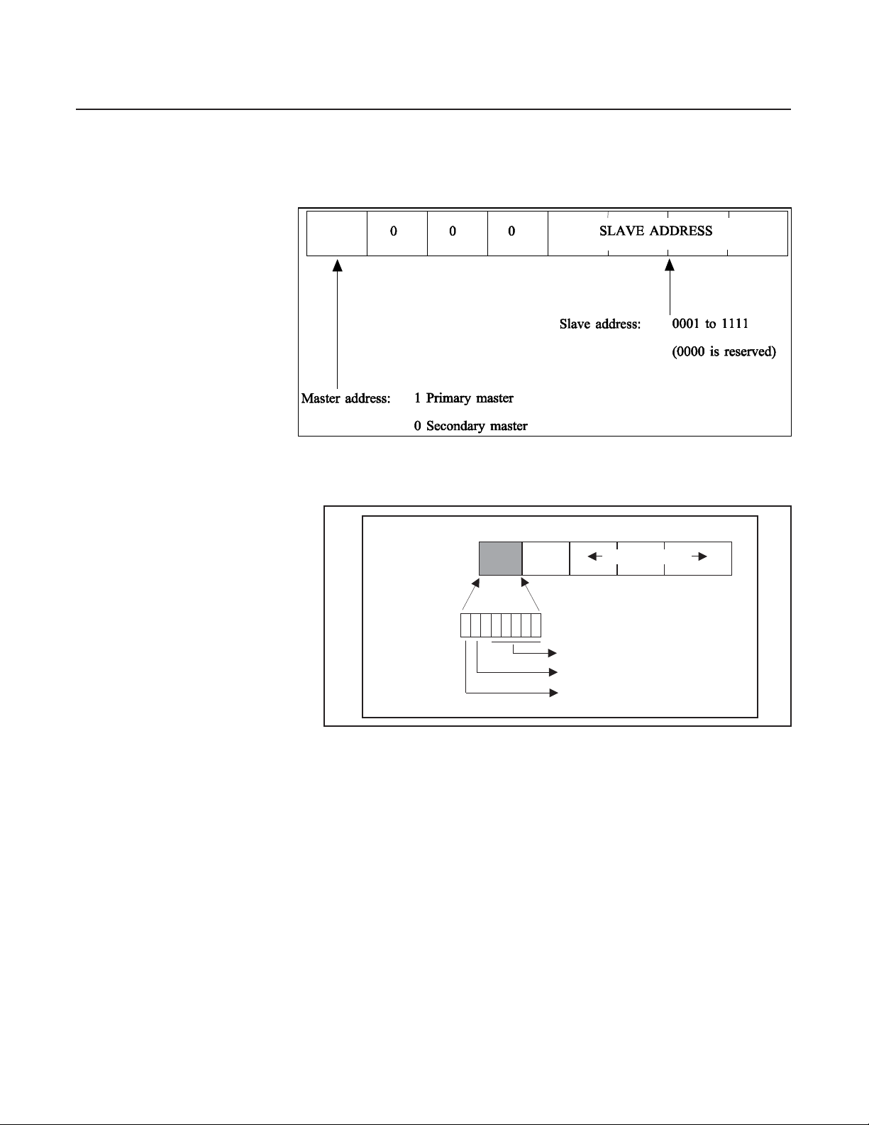
Figure 3-4 below shows the address character in the short frame format.
The 4 least significant bits are the slave address, which can be used as a
polling address.
Figure 3-4 Short Frame Address Character
In the long frame format the slave device address is represented by a
38-bit number. The structure of the address is given in Figure 3-5 below.
Figure 3-5 Long Frame Address Characters
In the long frame format the slave address part of the five address
characters is build up from three sources: The 6 bits of the first byte of the
slave address part represent the manufacturers code. In the case of FMA7400/7500 Series devices this is the number 10 (decimal). The
manufacturer number is a number which is stored in the device by the
manufacturer and which can not be changed by the user.
The second byte in the address is the device type code. This code
indicates the type of the device addressed. The device type code will be 90
for all FMA-7400/7500 Series RS485 Protocol devices. The device type
code is a number which is stored in the FMA-7400/7500 Series RS485
Protocol devices by the manufacturer and which can not be changed by
the user.
3-4
The last three bytes form a 24-bit unique identification number. As the
name implies, this value must be unique to each FMA-7400/7500 Series
RS485 Protocol device on a network. For legacy products this value
was derived from the serial number of the device, however for the FMA7400/7500 Series this value is a random value. Command #122 can be
used to change this value.
Page 21

3-4-5 Command Character
Section 3 Message Protocol Structure
FMA-7400/7500 Series Devices - RS485
A special case occurs when all bits of the slave address part are set to 0. A
message with this type of address, called a broadcast address, will be
accepted by all slave devices attached to the bus. A slave device will
always respond to a message with the broadcast address unless the
message contains additional information in the data portion of the message
that allows the slave device to determine that the message is not
addressed to that device. FMA-7400/7500 Series RS485 devices support
only one such command, Command #1 1. This type of addressing can be
used to address devices of which the manufacturer and the device type
codes and the unique identification number are not available to the host
system and with which this information can still be retrieved from the
unknown device. Command #1 1 dat a cont ains a Tag Name. Only a slave
device with the specified Tag Name will respond to Command #11 even if
the address in the message is the broadcast address. The T ag Name is an 8
character field which is equal to the last 8 digits of the device's serial number .
See Section 4-2 for a detailed description of the use of Command #11.
3-4-6 Byte Count Character
The command character is a 1 byte unsigned integer in the range from 0 to
255 (decimal), which indicates the action the slave device has to perform.
A larger range of commands is theoretically possible by using the
expansion code or 254 (decimal) followed by a second byte. This feature
however is not implemented by the FMA-7400/7500 Series RS485 devices.
The received command is echoed back by the slave device in its reply to
the master.
Three types of commands are available to the user: the ‘Universal
Commands’, the ‘Common-Practice Commands’ and the ‘TransmitterSpecific Commands’. The Universal Commands are a number of
commands in the range from 0 to 19, which are implemented by all field
devices utilizing the HART protocol. Refer to Section 6 for descriptions of
all available universal commands. The Common-Practice Commands are
a number of commands in the range from 32 to 127, which can be
implemented by all devices. These commands perform tasks which are
often common to most devices. Refer to Section 7 for descriptions of all
implemented Common-Practice Commands. The last category,
Transmitter-Specific Commands are a number of commands, ranging from
128 to 250 which are specific to the type of device. Refer to Section 8 for
descriptions of all available Transmitter-Specific Commands. The
commands #251 to #255 are reserved.
3-4-7 Status Characters
The bytecount character is a 1 byte unsigned integer indicating the number
of bytes which will form the remainder of the message. This number
includes the two status bytes (only if the message is a response message)
and the bytes in the data part. It does NOT include the checksum byte. The
byte count character is used by the receiving device to identify the
checksum byte and to determine when the message is finished.
Status Characters consists of two bytes, which cont ain bit-coded
information about communications errors, command errors, and device
3-5
Page 22

Section 3 Message Protocol Structure
FMA-7400/7500 Series Devices - RS485
status as defined in Table 3-2. Only response messages from the slave
Table 3-2 Status Byte Coding
Communication Bit 7 1 = Communication error Bit 7 0
errors
Bit 6 Parity error (hex C0) Bit 6
Bit 5 Overrun error (hex A0) Bit 5
Bit 4 Framing error (hex 90) Bit 4 All 0
Bit 3 Checksum error (hex 88) Bit 3
Bit 2 Reserved (hex 84) Bit 2
Bit 1 Rx Buffer Overflow (hex 82) Bit 1
Bit 0 Undefined Bit 0
Command Bit 7 0 = Communication error Bit 7 Device Malfunction
errors
device to the master device will contain status characters.
First Byte Second Byte
3-4-8 Data Characters
Bit 6 to 0 (not bit-mapped): Bit 6 Configuration Changed
Bit 5 Cold Start
0 Non command specific error Bit 4 More Status available. Use
1 Undefined Command # 48 to get more
2 Invalid selection information
3 Passed parameter too large Bit 3 Primary variable analog output
4 Passed parameter too small fixed
5 Incorrect byte count Bit 2 Primary variable analog output
6 Transmitter specific command error saturated
7 IIn write-protect mode Bit 1 Non primary variable out of
8-15 Command specific errors range
16 Access restricted Bit 0 Primary variable out of range
32 Device is busy
64 Commanded not implemented
If the communication failed (i.e. the slave received distorted information)
the first byte indicates the receiver error(s) of the slave device. The second
byte will then be 0. If communication did not fail, the first byte will give
command execution information, whereas the second byte will give
information on the status of the device. The command specific errors 8 15 are errors which can have a different meaning for different commands.
Refer to the Sections 6, 7 and 8 for more information.
For the commands that contain data, the data field may contain up to a
maximum of 24 8-bit data bytes. The dat a can appear in a number of
formats described in the following sections.
3-4-8-1 8-Bit Unsigned Integer Format
3-6
This format can be used to transfer codes (e.g unit codes), indexes (e.g
analog output numbers) and raw data. If a parameter , represented by an
8-bit unsigned integer in a command data part is not implemented, codes
like 250, “Not Used” or 0 will be used.
Page 23
3-4-8-2 24-Bit Unsigned Integer Format
This format can be used to transfer large integer data numbers (e.g. the
valve values).
3-4-8-3 IEEE 754 Floating Point Format
This format is based on the IEEE 754 single precision floating point
standard:
S EEEEEEE E MMMMMMM MMMMMMMM MMMMMMMM
byte # 0 byte # 1 byte # 2 byte # 3
Where: S - Sign of mantissa (1 = negative)
The value of a parameter described in the above format can thus be found
by:
V alue = S 1.M * 2
This format is also used in most personal computers.
The floating point parameters not used by a device will be filled with 7F A0
00 00 (hexadecimal) or ‘Not-A-Number’.
Section 3 Message Protocol Structure
FMA-7400/7500 Series Devices - RS485
E - Exponent; Biased by 127 in two’s complement format
M - Mantissa; 23 least significant bits, fractional portion
(E - 127)
3-4-8-4 ASCII Dat a Format
Some of the alphanumeric data passed by the protocol is transmitted to
and from the devices in the ASCII format. Refer to any ASCII Code table
for the alphanumeric code assignments.
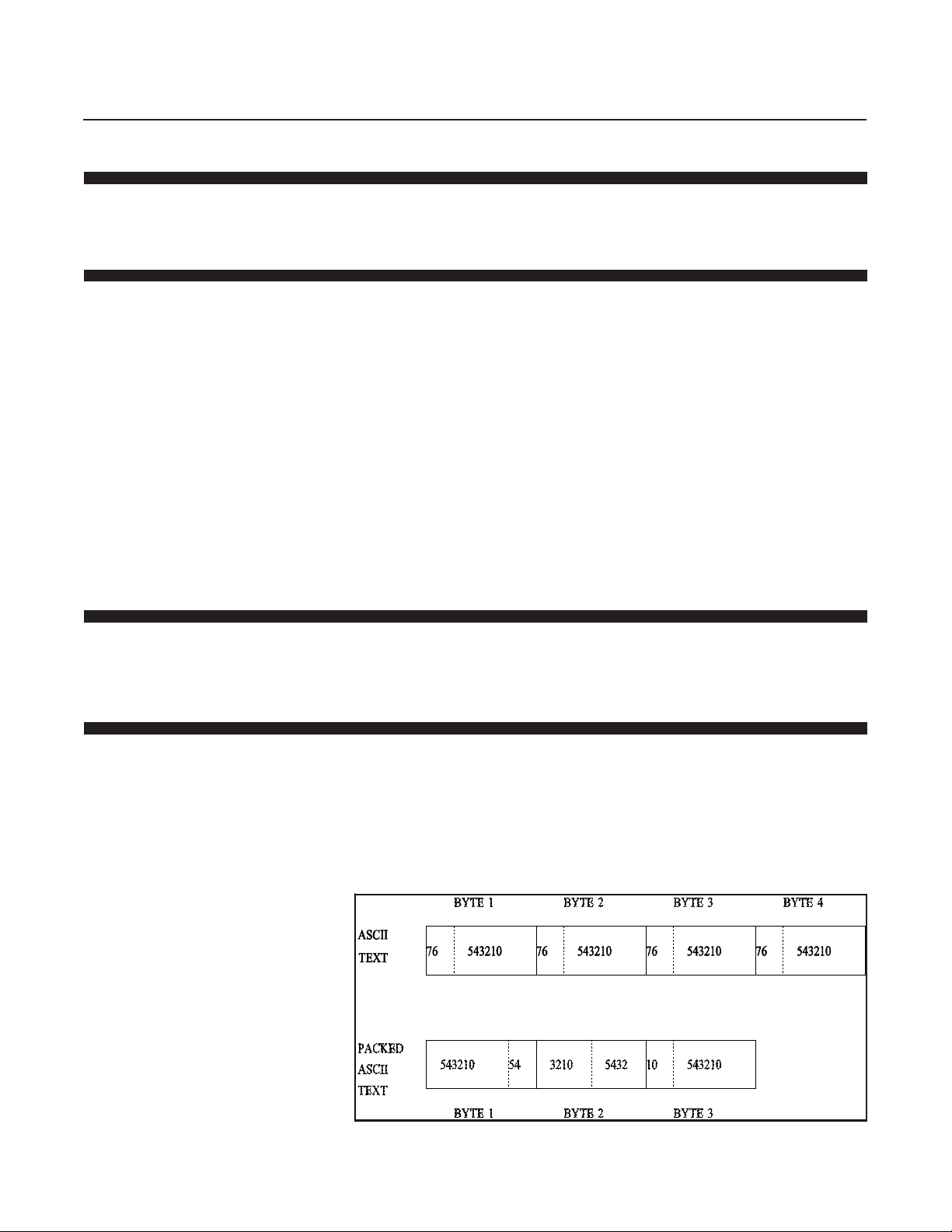
3-4-8-5 Packed-ASCII (6-bit ASCII) Data Format
Some of the alphanumeric data passed by the protocol is transmitted to
and from the devices in the Packed-ASCII format. Packed-ASCII is a
subset of ASCII (See Table 3-3) produced by removing the two most
significant bits from each ASCII character. This allows four Packed-ASCII
to be placed in the space of three ASCII characters. Typically four PackedASCII strings are even multiples of three bytes. Figure 3-6 illustrates the
byte sequence.
Figure 3-6 Packed-ASCII Construction
3-7
Page 24

Section 3 Message Protocol Structure
FMA-7400/7500 Series Devices - RS485
Construction of Packed-ASCII:
a. Remove bit #7 and bit #6 from each ASCII character.
b. Pack four 6-bit ASCII bytes into three bytes.
Reconstruction of ASCII characters:
a. Unpack the four 6-bit ASCII characters into four bytes.
b. Place the complement of bit #5 of each unpacked 6-bit ASCII
character into bit #6.
c. Set bit #7 of each unpacked ASCII to zero.
Table 3-3 Packed-ASCII Codes
Char Code Char Code Char Code Char Code
@ 00 P 10 (space) 20 0 30
A01 Q 11 ! 21 1 31
B 02 R 12 “ 22 2 32
C 03 S 13 # 23 3 33
D 04 T 14 $ 24 4 34
E 05 U 15 % 25 5 35
F 06 V 16 & 26 6 36
G 07 W 17 ‘ 27 7 37
H 08 X 18 ( 28 8 38
I 09 Y 19 ) 29 9 39
J 0A Z 1A * 2A : 3A
K 0B [ 1B + 2B ; 3B
L 0C \ 1C , 2C < 3C
M 0D ] 1D - 2D = 3D
N 0E ^ 1E . 2E > 3E
O 0F _ 1F / 2F ? 3F
3-4-8-6 Checksum Characters
3-8
The checksum byte contains the ‘exclusive-or’ (‘longitudinal parity’) of all
the characters preceding it in the message starting with the start character .
It provides a further check on transmission integrity , beyond the one
provided by the parity check on each individual byte. The exclusive-or of all
the message bytes (including the start character , excluding the checksum
byte) and the checksum byte itself should read exactly zero.
Page 25
4-1 Master/Slave Communications
Section 4 Master/Slave
Communications
FMA-7400/7500 Series Devices - RS485
Section 3 of this manual defined the RS485 Protocol message structure in
detail. Section 4 of this manual will describe how to utilize the RS485
message structure to perform master slave communications with a FMA7400/7500 Series RS485 device. This section focuses on RS485 line
handling, establishing communications with a device, error recovery , and
timing. Sections 6, 7, and 8 of this manual define all RS485 commands
available in FMA-7400/7500 Series RS485 devices. This section will
conclude with examples of typical communications sequences.
Master devices initiate all communications on a Master/Slave
communications network. Master devices are typically a computer of some
kind but other devices such as PLC’s can also operate as a Master device.
Slave devices only respond to messages initiated by a Master . FMA-7400/
7500 Series RS485 devices are always Slaves on the communications
network.
4-1-1 RS485 Line Handling
The physical communications layer used by FMA-7400/7500 Series
devices is RS485. On an RS485 physical communications layer, all dat a is
transmitted and received using differential signals on a single pair of wires.
Since both the Master and the Slave devices use the same pair of wires to
transmit their data, care must be taken to ensure that only one device has
its transmitter enabled at any point in time.
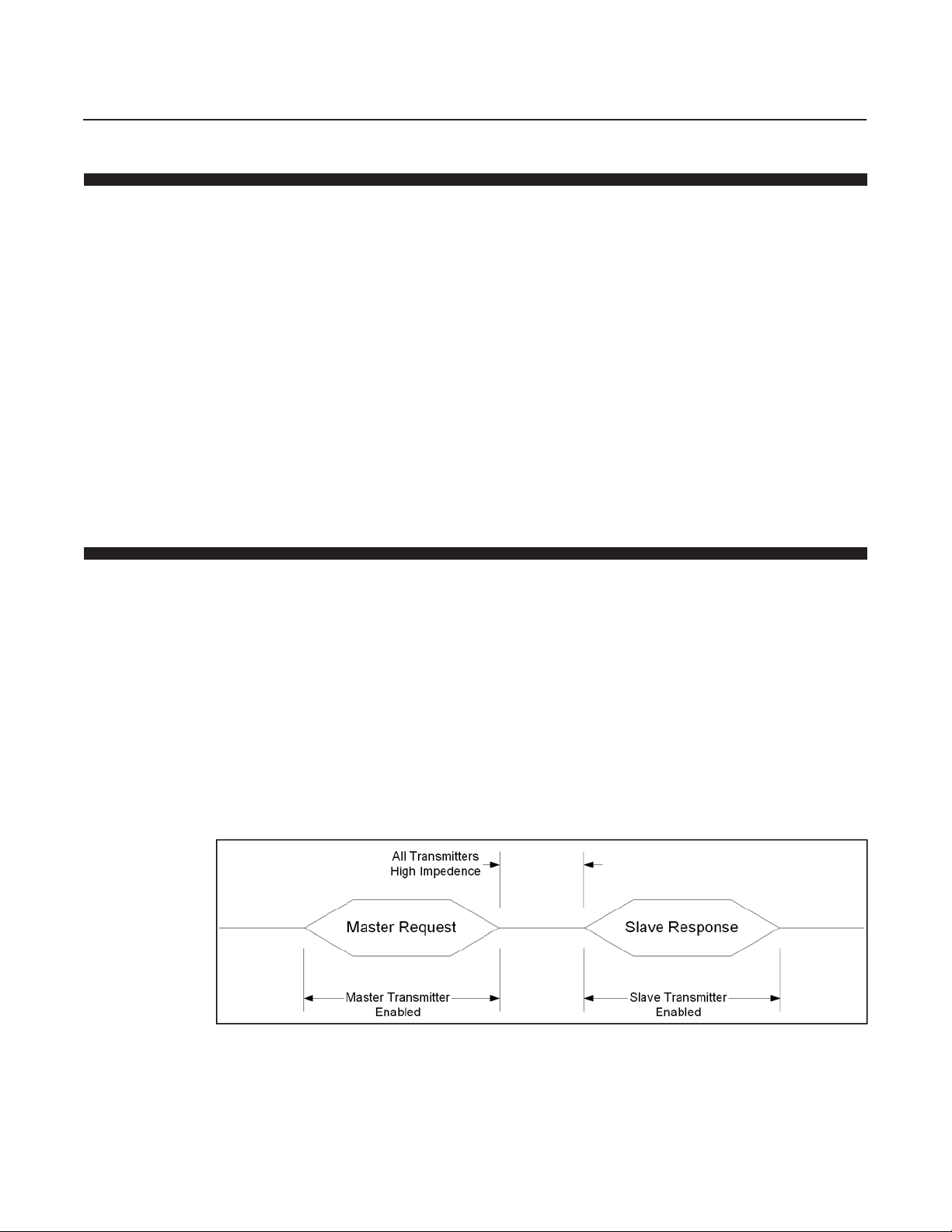
Figure 4-1 shows a typical message exchange using RS485. Notice that the
Master’s transmitter is enabled only during the Master Request message
and the Slave’s transmitter is enabled only during the Slave Response
message. At all other times, the transmitters on the Master and all Slaves
connected to the network must be in their high impedance state, leaving the
network “Un-Driven.”
Figure 4-1 T ypical Message Exchange Using RS485 Communications
4-1
Page 26

Section 4 Master/Slave
Communications
FMA-7400/7500 Series Devices - RS485
It is the user's responsibility to guarantee that the Master’s transmitter is
enabled only during the Master Request message. Control of the Master’s
transmitter is dependent upon the hardware used by the Master. If an
RS232 to RS485 converter is used, the most common control is the RTS
signal on the RS232 interface as shown in Figure 2-1 (See Section 2-2).
Refer to the user manual for your hardware to determine the proper control
method required in your system.
Timing the enabling/disabling of the transmitter is very important. The
transmitter must be enabled before the first bit of the first character is
transmitted and must be disabled only after the last bit of the last character
is transmitted. Additionally , all transmitters have some finite turn-on/turn-of f
delays which may be affected by the wire length and wire quality of your
network. The RS485 message structure attempts to minimize these affects
by requiring all messages to have at least 5 preamble characters while only
2 are required for the receiving device to detect a valid message (see
Section 3-4-2). This allows up to 3 lost characters due to
turn-on/turn-off delays.
Disabling a transmitter at the proper time is frequently a difficult task.
Many UARTS/systems do not provide an indication when the last byte of a
message is completely transmitted. It is more likely that an indication is
provided when the last byte of a message is starting to be transmitted.
Since the last byte of an RS485 message is the checksum byte for the
message, it is critical that the transmitter remain enabled until the last byte
is completely transmitted. One solution is to transmit an extra character at
the end of a message (typically 0x00) and then disable the transmitter when
the indication is received that the extra character is starting to be
transmitted. However, the transmitter cannot be enabled too long af ter a
message is complete. Slave devices will begin transmitting a response as
soon as 5 msec after the reception of an error free request message.
High data rates increase the importance of disabling the transmitter
quickly . At 19200 baud, one character time is 0.57 msec. Thus, the 3 lost
character “cushion” represents only 1.72 msec. While the response of a
FMA-7400/7500 Series RS485 device is always at least 5 msec regardless
of the data rate, lower data rates provide a longer “cushion” and thus is a
possible solution if disabling the transmitter in a timely manner proves
difficult. Another solution is to increase the number of preamble characters
transmitted by the Master and/or the slave.
4-2 Establishing Communications with a Device
4-2
In order for a Master to establish communications with a FMA-7400/7500
Series RS485 device, the Master must know the address of the device. The
RS485 Protocol supports both Short Frame Addressing and Long Frame
Addressing as defined in Section 3-2.
Page 27
Section 4 Master/Slave
Communications
FMA-7400/7500 Series Devices - RS485
Short Frame Addressing allows a master to communicate with up to 15
devices. Each device on the network must have a unique Polling Address
with a value of 1–15. Short Frame Addressing has one side effect which
will be undesireable in many applications. If the Polling Address is set to a
non-zero value (as required for Short Frame Addressing), the Primary
Analog Output will be fixed at the low range of the output and will not
respond to the applied process. If your system requires the use of the
Primary Analog Ouput, then Long Frame Addressing must be used.
Long Frame Addressing allows a master to communicate with up to
16,777,215 devices on a wide area network (RS485 has a limit of 32
devices per daisy chain). Each device is pre-programmed at the factory
with a unique long address. Using the process described below, the Master
can obtain the long address from the device by knowing only the device
Tag Name. The Tag Name is pre-programmed at the factory and is printed
on the devices’s calibration sheet.
The following procedure can be performed online in order to obtain a
device’s long address:
1.Send Command #1 1 (See Section 6-6) using Long Frame Addressing
and an address of 0. In the data section of Command #11, use the
device’s Tag Name to identify the device. Command #11 requires that the
Tag Name be transmitted in Packed-ASCII format as defined in Section
3-4-8-5.
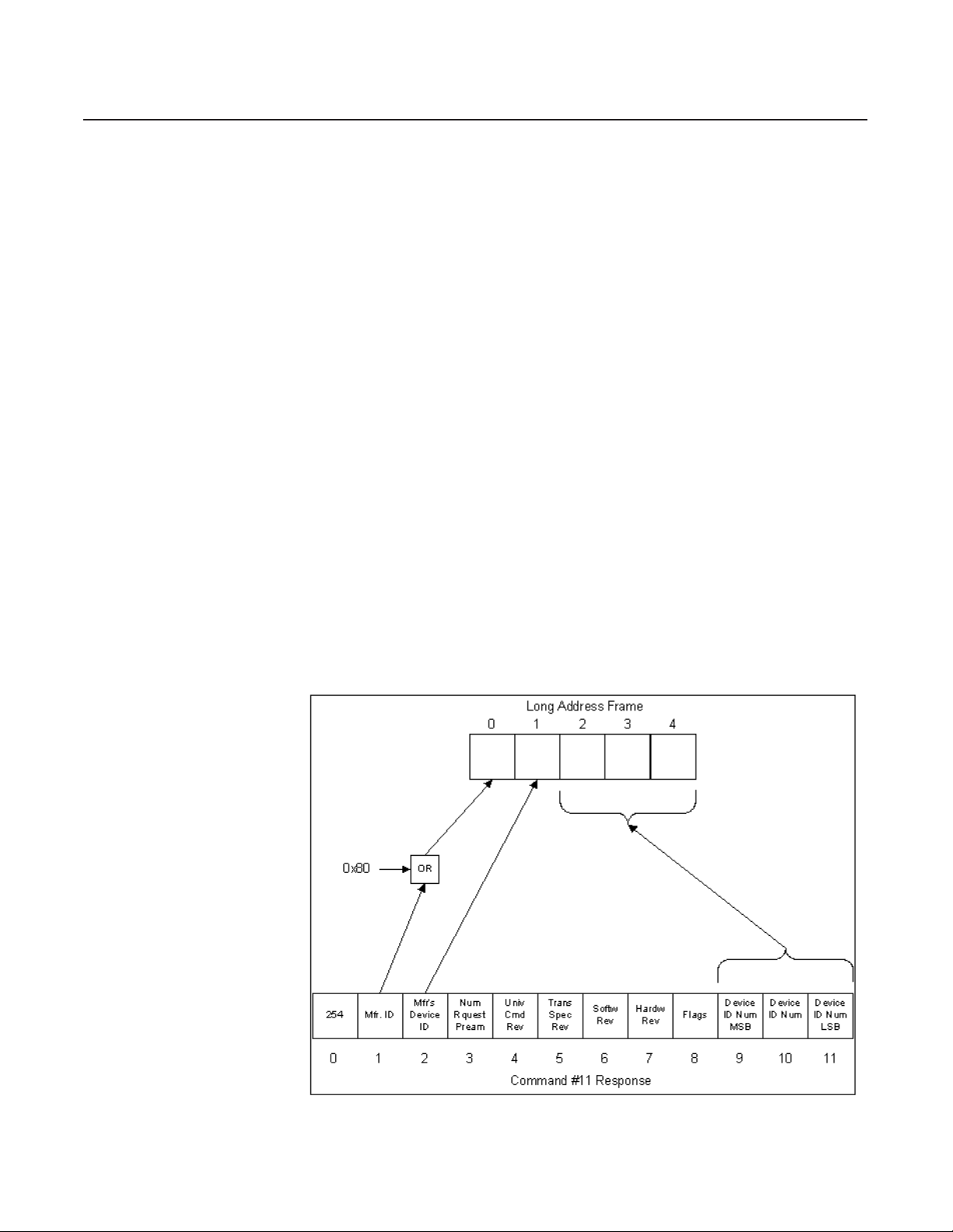
2.Extract the Manufacturer ID, Manufacturer’s Device ID, and Device ID
Number from the response and construct the Long Address Frame as
shown in Figure 4-2.
Figure 4-2 Command #11 Response to Long Frame Address
4-3
Page 28
Section 4 Master/Slave
Communications
FMA-7400/7500 Series Devices - RS485
4-2-1 Example of Using Command #1 1
Command #1 1 reads the unique identifier from a device whose Tag Name
is specified in the Command #1 1 request from the Master. Tag Names are
strings of up to 8 characters which are limited to the reduced ASCII set
defined in Table 3-3. A Tag Name consists of the last 8 digits of the device's
serial number . Table 4-1 is an example of converting an 8 character T ag
Name to 6 bytes in the Packed-ASCII format. In this example, the Tag
Name of the device will be “MFC-1234”.
Table 4-1 Converting Tag Name to Packed ASCII
Representation
Tag Name MFC-1234
Characters M F C - 1 2 3 4
8- bit ASCII (hex) 4D 46 43 2D 31 32 33 34
Bit 7 & 8 removed:
6 bit ASCII (hex) 0D 06 03 2D 31 32 33 34
6 bit ASCII (binary) 001 101 000110 000011 101101 110001 110010 110011 1 10100
Packed (binary) 001 10100 01 10 0000 11101 101 1 1000111 00101 100 11 110100
Packed (hex) 34 60 ED C7 2C F4
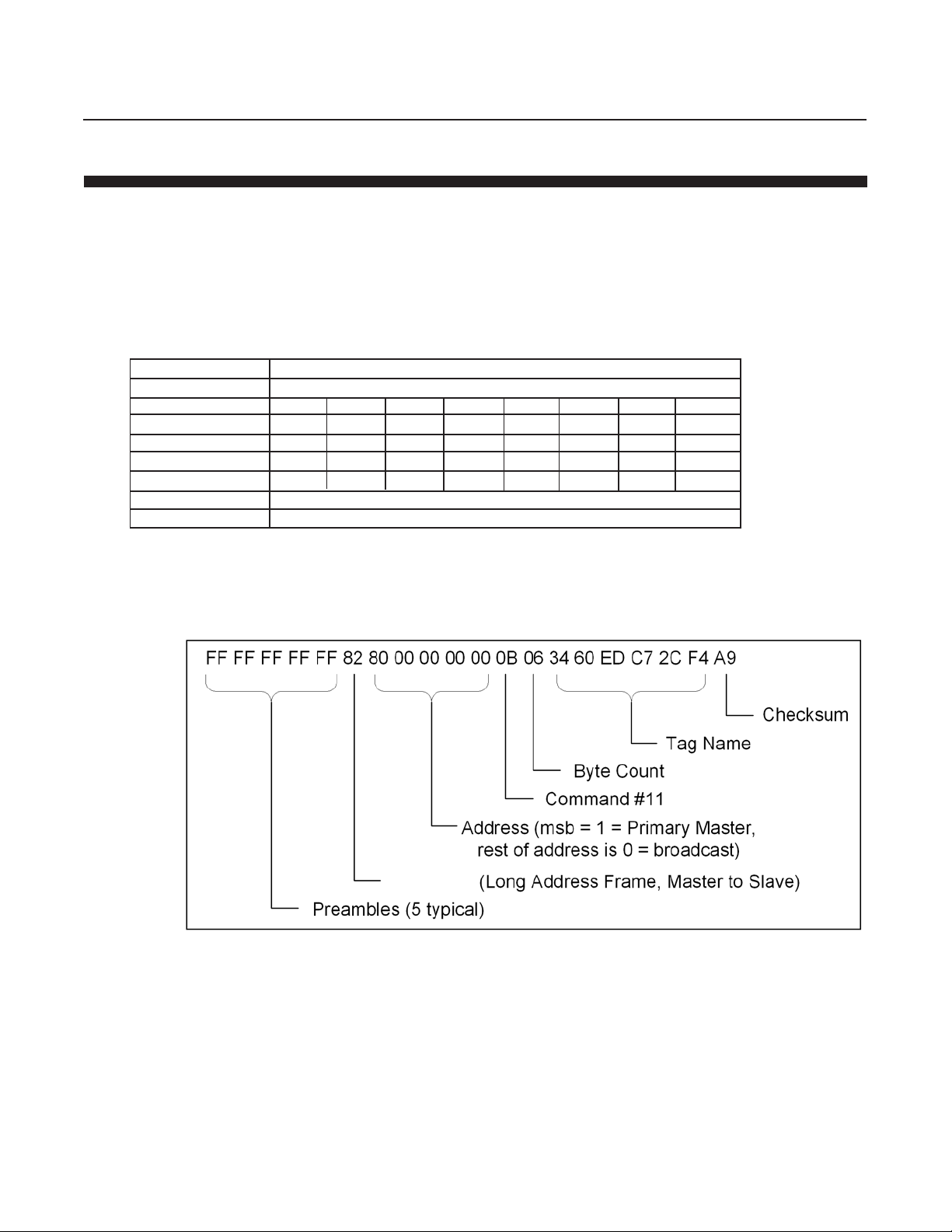
Figure 4-3 shows the request message for Command #1 1 sent by the
Master to the FMA-7400/7500 Series RS485 Protocol device whose T ag
Name is MFC-1234.
Delimiter
Figure 4-3 Command #11 Master Request
4-4
Page 29
Section 4 Master/Slave
Communications
FMA-7400/7500 Series Devices - RS485
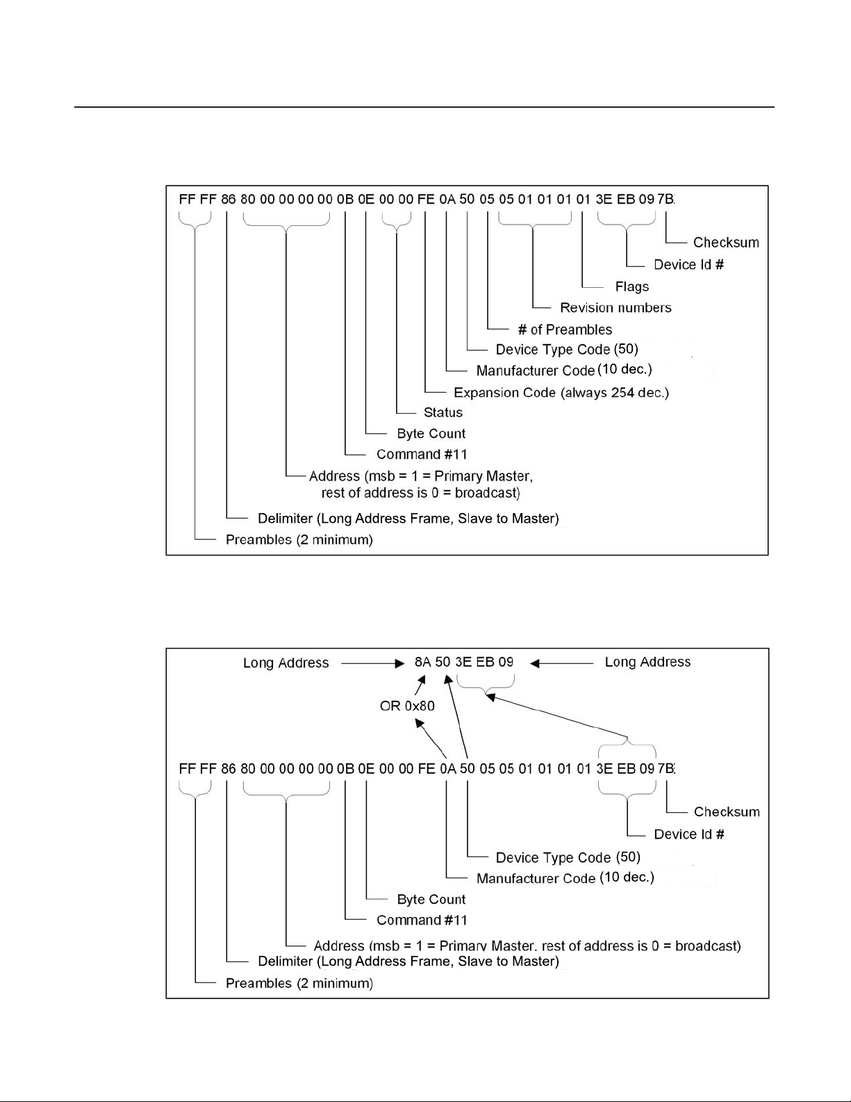
A possible Response Message from a FMA-7400/7500 Series
RS485 device is shown in Figure 4-4.
Figure 4-4 Command #11 Response Message
From the response, the long address can be extracted as shown in Figure
4-5.
Figure 4-5 Extracting the Long Address
4-5
Page 30

Section 4 Master/Slave
Communications
FMA-7400/7500 Series Devices - RS485
4-3 Alarm Configuration and Monitoring
FMA-7400/7500 Series RS485 devices monitor for various alarm conditions
such as Flow Rate, T ot alizer Overflow, and Diagnostics. To determine
which alarms conditions have been detected, use Command #48 (See
Section 7-3). However, it is not necessary to const antly poll Command #48
to determine when an alarm condition has been detected. All slave
response messages contain a 2 byte status. If an alarm condition has been
detected, then bit 4 of the second status byte will indicate “More S tatus
Available”. Then Command #48 can be used to determine the alarm
condition(s) that has been detected.
To configure which alarm conditions are monitored and reported by the
device, refer to Commands 245, 246, 247, and 248 in Section 7, also
Table 9-15.
4-4 Error Handling
In all communications networks, communications errors can and will occur.
Both the Master and the Slave devices must be able to properly handle
errors in order to maintain a operating network. When a FMA-7400/7500
Series RS485 device detects a communications error, one of two result s
may occur. It may respond with an error code, or it may not respond at all
to the request. The result depends upon the type of error that was detected,
and where in the message the error was detected. It is important that the
Master handles the situation correctly .
There are two basic type of errors defined by the RS485 Protocol:
Communications Errors and Command Response errors. The type of error
can be determined by examining the Status Code returned by the slave
device (See section 3-4-7). Command Response errors are typically the
result of a programming error in the Master and should not normally occur
in a mature system. The main focus of this section will be Communication
Errors.
Communications Errors are frequently the result of external environment
issues, faulty wiring, etc. In a properly designed network, Communications
Errors should be rare. A Communications Error can occur in either the
Master to Slave Request or the Slave to Master response. If the error
occurs in a Master to Slave request, one of two results may occur . It may
respond with an error code, or it may not respond at all to the request. The
result depends upon the type of error that was detected, and where in the
message the error was detected. It is the responsibility of the Master
device to check all Slave to Master responses for errors including
message frame formatting, longitudinal parity , and vertical p arity.
4-6
Page 31

Section 4 Master/Slave
Communications
FMA-7400/7500 Series Devices - RS485
Regardless of the type of error and when or where it was detected, the
normal way to handle a Communications Error is to simply retry the
message. Typically , a master would attempt to retry a message at least
twice to allow any external disturbance to clear. In the event that the retries
are unsuccessful, then the Master device must handle the situation in a
manner consistent with the requirements of the system. T ypical responses
to such an error are: Taking the device off-line so that the remainder of the
network is not affected; Notifying an operator; T riggering a system alarm;
etc.
A Master device must allow sufficient time for a Slave to respond before
attempting to retry the message. The average response time for a FMA7400/7500 Series RS485 device is less than 1 msec, but it is possible to for
the response to be as along as 10 msec. The Master should wait 4 times the
maximum response time (40 msec) before retrying the message. As long as
communications errors are infrequent, this retry delay time should not
affect system performance.
4-5 Examples
4-5-1 Reading Flow Rate
The following 2 examples show the most typical messages used by a
Master when communicating to a FMA-7400/7500 Series RS485 device:
Reading Flow Rate and Sending the Setpoint. These examples will use the
Long Addressing Frame with the long address est ablished in the example in
Section 4-2-1. The calibrated full scale of the device used in these
examples is 1.0 liters per minute.
The flow rate of the device can be read using any of the following
commands:
• Command #1 – Read Primary Variable
• Command #2 – Read Primary V ariable Current and Percent of Range
• Command #3 – Read Current and All Dynamic Variables
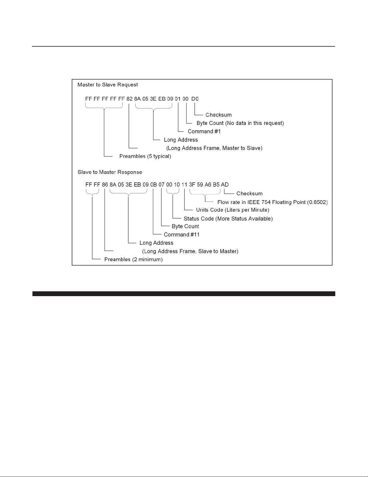
This example will use Command #1 to read the Flow Rate of the device.
This command returns the flow rate in the unit of measure as configured in
the device. The units can be changed using Command #196, Select Flow
Unit.
In the example shown in Figure 4-6, the device returns a flow of 0.8502
liters/min.
4-7
Page 32
Section 4 Master/Slave
Communications
FMA-7400/7500 Series Devices - RS485
Delimiter
Figure 4-6 Reading Flow Rate Example
4-5-2 Sending the Setpoint
Delimiter
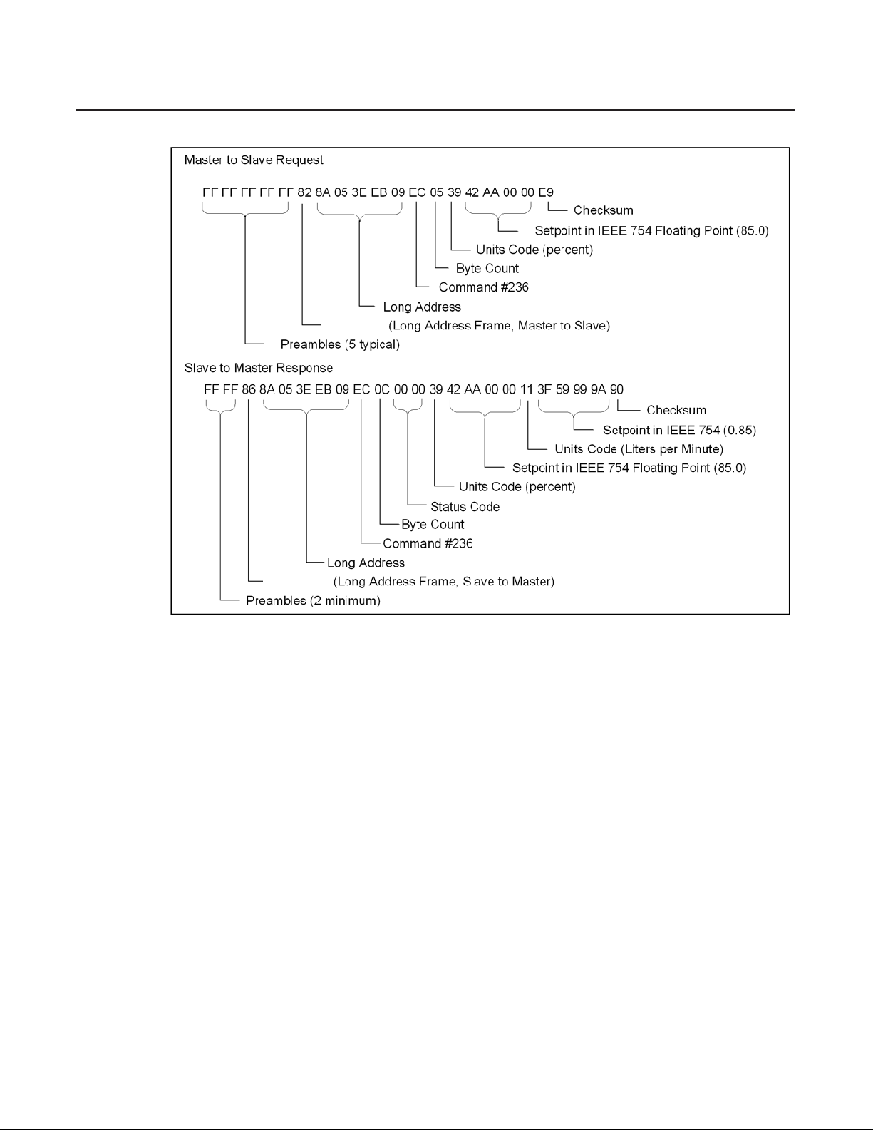
The Setpoint can be controlled via the network using Command #236. In
the example shown in Figure 4-7, the setpoint is set to 85% of full scale.
If Setpoint is controlled via an analog input, then Setpoint can be read
using Command #235.
When Command #236 is received by a FMA-7400/7500 Series RS485
device, the Setpoint Source is automatically changed to digital mode.
Setpoint source can be changed back to analog by using Command #216
or by cycling power to the device.
4-8
Page 33
Delimiter
Section 4 Master/Slave
Communications
FMA-7400/7500 Series Devices - RS485
Delimiter
Figure 4-7 Writing Setpoint Example
4-9
Page 34

Section 4 Master/Slave
Communications
FMA-7400/7500 Series Devices - RS485
THIS PAGE WAS
INTENTIONALLY
LEFT BLANK
4-10
Page 35

5-1 Referenced Documents
5-2 Unit Conversions
5-2-1 Flow Rate Conversions
Section 5 General Transmitter
Information
FMA-7400/7500 Series Devices - RS485
The following HART documents where referenced in order to implement
the protocol:
Data Link Layer Specification Rev. HCF_SPEC-81 Rev 7.1
Command Summary Information Rev. HCF_SPEC-99 Rev 7.1
Command-Specific Response Code Defs. Rev. HCF_SPEC-307 Rev 4.1
Universal Command Specification Rev. HCF_SPEC-127 Rev 5.2
Common-Practice Command Specification Rev. HCF_SPEC-151 Rev 7.1
Common Tables Rev. HCF_SPEC-183 Rev 11.0
All flow values involved in the exchange of data during communication are
converted to/from the user specified flow units. A list of supported flow
units is provided in Section 8-3. The user can change the flow units to be
used for all flow rate conversions with Command #196.
V olume flow units are always reported at specific reference conditions.
Using Command #196, the user can select reference condition type from 3
options as listed in Section 8-3.
· Normal - reference conditions of 0 °C and 1 atmosphere. ( 273.15
degrees K/ 101325 Pascals).
· Standard – user specified reference conditions.
· Calibration – reference conditions used at calibration.
5-1
Page 36

Section 5 General Transmitter
Constant=
T
V
P
=
T
V
P
2
2
2
1
1
1
··
V
*
)
TP
(
)
TP
(
=
V
1
12
21
2
·
·
Information
FMA-7400/7500 Series Devices - RS485
Reference condition conversions are done using the Boyle-Gay-Lussac law
Where P is pressure, T is temperature and V is volume (per unit of time).
The indexes 1 and 2 represent the two different reference conditions. This
results in the reference conversion formula
Where applicable the conversion factors are taken from The Handbook of
Chemistry and Physics, 60th edition, R.C. Weast (Ed.), CRC Press Inc.,
Cleveland, Ohio.
5-2-2 T emperature Conversions
(1)
(2)
All temperature values involved in the exchange of data during
communication are converted to/from the user specified temperature units.
A list of supported temperature units is provided in Section 8-5. The user
can change the temperature units to be used for all temperature
conversions with Command #197.
5-2
Page 37

Section 6 Universal
Command Specifications
FMA-7400/7500 Series Devices - RS485
6-1 Command # 0 Read Unique Identifier
Command used to retrieve the expanded device-type codes, revision levels
and the device identification number from the specified device. The device
type code will always be returned in the expanded three byte format (i.e.
“254”, manufacturer identification code, manufacturers device type code).
The combination of the manufacturer identification code, manufacturer’s
device type code and device identification code make up the unique
identifier for the extended frame format of the data link layer.
Request data bytes:
NONE
Response data bytes:
254 MFR. ID MFR's NUMBER UNIV. TRANS. SOFTW HARDW FLAGS DEVICE DEVICE DEVICE
DEVICE RQUEST CMD. SPEC. REV. REV. ID NUM ID NUM ID NUM
TYPE PREAM REV. REV . MSB
#0 #1 #2 #3 #4 #5 #6 #7 #8 #9 #10 #11
Data Type Remarks
Byte #
0 8-bit unsigned integer Device type code for “expansion”.
Contains the code “254” (decimal).
1 8-bit unsigned integer Manufacturer identification code.
(Always 10).
2 8-bit unsigned integer Manufacturers device type code.
Refer to Section 9-2, Device type codes.
3 8-bit unsigned integer Number of response preamble characters
required for the request message from the master to the
slave.
4 8-bit unsigned integer Universal command revision level implemented by this
device.
5 8-bit unsigned integer Transmitter specific command revision level
implemented by this device.
6 8-bit unsigned integer Software revision level of the device.
7 8-bit unsigned integer Hardware revision level of the electronics in the device.
Format: xxxxx.yyyB
x - Device hardware revision level, 5-bit unsigned
integer, level 15 is reserved.
y - Physical signalling code, 3-bit unsigned integer,
refer to Section 9-8, Physical signalling codes.
8 8-bit unsigned integer Flags. Refer to Section 9-10, Flag assignments.
9 - 1 1 24-bit unsigned integer Device identification number.
6-1
Page 38

Section 6 Universal
Command Specifications
FMA-7400/7500 Series Devices - RS485
6-1-1 Command #0 Specific Response Codes
0 No command-specific errors
1 - 4 Undefined
5 Incorrect bytecount
6 - 127 Undefined
6-2 Command #1 Read Primary Variable
Read the primary variable. The primary variable is the flow rate of the
device expressed in the selected flow units at the selected flow reference
conditions. See Command #196 for information on setting Flow Units, and
Flow Reference conditions.
Request data bytes:
NONE
Response data bytes:
SEL. FLOW FLOW FLOW FLOW
FLOW RATE RATE RATE RATE
UNIT MSB LSB
#0 #1 #2 #3 #4
Data Type Remarks
Byte #
0 8-bit unsigned integer Primary variable unit code.
Refer to Section 9-3, Flow rate
unit and reference codes.
1 - 4 32-bit floating point, Primary variable: flow rate.
IEEE 754 format
6-2
Page 39

FMA-7400/7500 Series Devices - RS485
6-2-1 Command #1 Specific Response Codes
0 No command-specific errors
1 - 4 Undefined
5 Incorrect bytecount
6 - 127 Undefined
6-3 Command #2 Read Primary Variable Current and Percent Range
Read the primary variable, flow rate, as current or voltage and as a percent
of the primary variable range. For FMA-7400/7500 Series RS485 Protocol
devices, the current/voltage field reports current in mAmps or voltage in
volts depending upon the configuration of the output of the device. The
current/voltage always matches the analog output of the device including
alarm conditions and set values. Percent of range always follows the
primary variable, even if the current is in an alarm condition or set to a
value. Also, the percent of range is not limited to values between 0% and
100%, but tracks the primary variable to the sensor limits.
Section 6 Universal
Command Specifications
Request data bytes:
NONE
Response data bytes:
CURRENT/ CURRENT/ CURRENT/ CURRENT/ PV PV PV PV
VOLTAGE VOLTAGE VOLTAGE VOLTAGE % RANGE % RANGE % RANGE % RANGE
MSB LSB MSB LSB
#0 #1 #2 #3 #4 #5 #6 #7
Data Type Remarks
Byte #
0 - 3 32-bit floating point, Analog output current or
IEEE 754 format voltage [milliamperes or
volts].
4 - 7 32-bit floating Point, Primary variable: flow
IEEE 754 format rate [% of range]
6-3-1 Command #2 Specific Response Codes
0 No command-specific errors
1 - 4 Undefined
5 Incorrect bytecount
6 - 127 Undefined
6-3
Page 40

Section 6 Universal
Command Specifications
FMA-7400/7500 Series Devices - RS485
6-4 Command #3 Read Current and all Dynamic Variable
Read the current and the dynamic variables. The current/voltage field
reports current in mAmps or voltage in volt s depending upon the
configuration of the output of the device. The current/voltage always
matches the analog output current/voltage of the device including alarm
conditions and set values. For the FMA-7400/7500 Series RS485 Protocol
devices, the dynamic variable assignments are as follows:
V ariable #0: Flow Rate (Primary V ariable)
V ariable #1: T emperature (Secondary Variable)
Request data bytes:
NONE
Response data bytes:
CURRENT/ CURRENT/ CURRENT/ CURRENT/ PRIMARY PRIMARY PRIMARY PRIMARY
VOL TAGE VOLTAGE VOLT AGE VOL TAGE VAR. VAR. V AR. VAR.
MSB LSB UNITS
#0 #1 #2 #3 #4 #5 #6 #7
PRIMARY SECOND. SECOND. SECOND. SECOND. SECOND.
VAR. VAR. VAR. VAR. VAR. VAR.
LSB UNITS MSB LSB
#8 #9 #10 #11 #12 #13
Data Type Remarks
Byte #
0 - 3 32-bit floating point, Analog output current/
IEEE 754 format voltage [milliamperes
or volts].
4 8-bit unsigned integer Primary variable unit
code.Refer to Section
9-3, Flow rate unit and
reference codes.
5 - 8 32-bit floating point, Primary variable: flow
IEEE 754 format rate.
6-4
Page 41

FMA-7400/7500 Series Devices - RS485
9 8-bit unsigned integer Secondary variable unit
code.Refer to Section
9-5, Temperature unit
codes.
10 - 13 32-bit floating point, Secondary variable:
IEEE 754 format temperature.
6-4-1 Command #3 Specific Response Codes
0 No command-specific errors
1 - 4 Undefined
5 Incorrect bytecount
6 - 127 Undefined
Section 6 Universal
Command Specifications
6-5 Command #6 Write Polling Address
This command writes the Polling Address (Short Frame Address) to the
field device.
Request data bytes:
POLLING
ADDRESS
Data Type Remarks
Byte #
0 8-bit unsigned integer Polling Address:
#0
0-15
16-255 Undefined
6-5
Page 42

Section 6 Universal
Command Specifications
FMA-7400/7500 Series Devices - RS485
Response data bytes:
POLLING
ADDRESS
#0
Data Type Remarks
Byte #
0 8-bit unsigned integer Polling Address:
0-15
16-255 Undefined
6-5-1 Command #6 Specific Response Codes
0 No command-specific errors
1 Undefined
2 Invalid selection
3-4 Undefined
5 Incorrect bytecount
6 Undefined
7 In write protect mode
8-15 Undefined
16 Access restricted
17 -127 Undefined
6-6 Command #1 1 Read Unique Identifier associated with Tag
This command returns the expanded device-type codes, revision levels
and the device identification number of a device containing the requested
tag. It will be executed when either the appropriate long address or the
broadcast long address, “00000” is received. The address field in the
response message of this command always contains the address received
in the request message. This command is unique in that no response is
made unless the tag matches that of the device.
Request data bytes:
TAG TAG TAG TAG TAG TAG
#0 #1 #2 #3 #4 #5
Data Type Remarks
Byte #
0 6(8-bit) byte packed ASCII Device tag number
6-6
Page 43

Section 6 Universal
Command Specifications
FMA-7400/7500 Series Devices - RS485
Response data bytes:
254 MFR. ID MFR's NUMBER UNIV. TRANS. SOFTW HARDW FLAGS DEVICE DEVICE DEVICE
DEVICE RQUEST CMD. SPEC. REV. REV. ID NUM ID NUM ID NUM
TYPE PREAM REV. REV. MSB
#0 #1 #2 #3 #4 #5 #6 #7 #8 #9 #10 #11
Data Type Remarks
Byte #
0 8-bit unsigned integer Device type code for "expansion".
Contains the code "254" (decimal).
1 8-bit unsigned integer Manufacturer identification code.
(Always 10).
2 8-bit unsigned integer Manufacturers device type code.
Refer to Section 9-2, Device type code.
3 8-bit unsigned integer Number of response preamble characters
required for the request message from the
master to the slave.
4 8-bit unsigned integer Universal command revision level implemented
by this device.
5 8-bit unsigned integer Transmitter specific command revision level
implemented by this device.
6 8-bit unsigned integer Software revision level of the device.
7 8-bit unsigned integer Hardware revision level of the electronics in the
device. Format: xxxxx.yyyB
x- Device hardware revision level,
5-bit unsigned integer, level 15 is reserved.
y- Physical signalling code, 3-bit unsigned
integer, refer to Section 9-8, Physical signalling
codes.
8 8-bit unsigned integer Flags
Refer to Section 9-10, Flag assignments.
9-1 1 24-bit unsigned integer Device identification number.
6-6-1 Command #11 Specific Response Codes
0 No command-specific errors
1 - 4 Undefined
5 Incorrect bytecount
6 - 127 Undefined
6-7
Page 44

Section 6 Universal
Command Specifications
FMA-7400/7500 Series Devices - RS485
6-7 Command #12 Read Message
Read the 32 Character Message String contained within the device. The
message string is a 32 character storage area that the user may use for
any application related function desired. The message string is not used by
the device.
Request data bytes:
NONE
Response data bytes:
MESSAGE MESSAGE MESSAGE MESSAGE MESSAGE MESSAGE MESSAGE MESSAGE MESSAGE MESSAGE MESSAGE MESSAGE
#0 #1 #2 #3 #4 #5 #6 #7 #8 #9 #10 #11
MESSAGE MESSAGE MESSAGE MESSAGE MESSAGE MESSAGE MESSAGE MESSAGE MESSAGE MESSAGE MESSAGE MESSAGE
#12 #13 #14 #15 #16 #17 #18 #19 #20 #21 #22 #23
Data Type Remarks
Byte #
0-23 24(8-bit) byte packed ASCII 32 character message string.
6-7-1 Command #12 Specific Response Codes
0 No command-specific errors
1 - 4 Undefined
5 Incorrect bytecount
6 - 127 Undefined
6-8
Page 45

Section 6 Universal
Command Specifications
FMA-7400/7500 Series Devices - RS485
6-8 Command #13 Read tag, Descriptor , Date
Read the tag, descriptor and date contained within the device. The tag
name is used to identify the device (See Command #1 1). The description
and date fields can be utilized for any application specific function desired.
The description and date fields are not used by the device.
Request data bytes:
NONE
Response data bytes:
TAG TAG TAG TAG TAG TAG DESCRIPT. DESCRIPT. DESCRIPT. DESCRIPT. DESCRIPT. DESCRIPT.
#0 #1 #2 #3 #4 #5 #6 #7 #8 #9 #10 #11
DESCRIPT . DESCRIPT. DESCRIPT. DESCRIPT. DESCRIPT . DESCRIPT. DATE DATE DATE
#12 #13 #14 #15 #16 #17 #18 #19 #20
DAY MONTH MONTH
Data Type Remarks
Byte #
0-5 6(8-bit) byte packed ASCII Device tag name.
6-17 12(8-bit) byte packed ASCII Device descriptor . (16 character string)
18-20 3(8-bit) byte packed ASCII Date.Respectively day , month,
year - 1900.
6-8-1 Command #13 Specific Response Codes
0 No command-specific errors
1 - 4 Undefined
5 Incorrect bytecount
6 - 127 Undefined
6-9
Page 46

Section 6 Universal
Command Specifications
FMA-7400/7500 Series Devices - RS485
6-9 Command #14 Read Primary Variable Sensor Information
This command is intended to read primary variable sensor information.
Request data bytes:
NONE
Response data bytes:
SENSOR
SERIAL
NUM
MSB
#0 #1 #2 #3 #4 #5 #6 #7 #8 #9 #10 #11
MIN
SPAN
MSB
#12 #13 #14 #15
SENSOR
SERIAL
NUM
MIN
SPAN
SENSOR
SERIAL
NUM
LSB
MIN
SPAN
LIMITS
UNITS
CODE
MIN
SPAN
LSB
UPPER
SENSOR
LIMIT
MSB
UPPER
SENSOR
LIMIT
UPPER
SENSOR
LIMIT
UPPER
SENSOR
LIMIT
LSB
LOWER
SENSOR
LIMIT
MSB
LOWER
SENSOR
LIMIT
LOWER
SENSOR
LIMIT
Data Type Remarks
Byte #
0 - 2 24-bit unsigned integer Sensor serial number.
3 8-bit unsigned integer Sensor limits/minimum span unit code.
4 - 7 32-bit floating point, Upper sensor limit.
IEEE 754 format
LOWER
SENSOR
LIMIT
LSB
8 - 1 1 32-bit floating point, Lower sensor limit.
IEEE 754 format
12 – 15 32-bit floating point, Minimum span.
IEEE 754 format
6-9-1 Command #14 Specific Response Codes
0 No command-specific errors
1 - 4 Undefined
5 Incorrect bytecount
6 - 127 Undefined
6-10
Page 47

Section 6 Universal
Command Specifications
FMA-7400/7500 Series Devices - RS485
6-10 Command #15 Read Output Information
This command is intended to read the alarm selection code, transfer
function, primary variable/range unit code, upper range value, lower range
value, damping value (applied to the sensor , not the output), write protect
code and private label distributor.
Request data bytes:
NONE
Response data bytes:
ALARM TRANSF. PV / RANGE UPPER UPPER UPPER UPPER LOWER LOWER LOWER LOWER DAMPING
SELECT FUNCT. UNITS RANGE RANGE RANGE RANGE RANGE RANGE RANGE VALUE VALUE
CODE CODE CODE MSB MSB MSB MSB
#0 #1 #2 #3 #4 #5 #6 #7 #8 #9 #10 #11
DAMPING DAMPING DAMPING WRITE PVT
VALUE VALUE VALUE PROTECT LABEL
LSB CODE DIST
#12 #13 #14 #15 #16
Data Type Remarks
Byte #
0 8-bit unsigned integer Alarm select code.
Not implemented for the FMA-7400/7500 Series RS485
Protocol devices, the integer returned is a “Not-Used”
or “250” (decimal).
1 8-bit unsigned integer Transfer function code.
Always returns LINEAR (0)
2 8-bit unsigned integer Primary variable upper and lower range unit code.
3 - 6 32-bit floating point, Upper range value.
IEEE 754 format
7 - 10 32-bit floating point, Lower range value.
IEEE 754 format
6-11
Page 48

Section 6 Universal
Command Specifications
FMA-7400/7500 Series Devices - RS485
Data Type Remarks
Byte #
1 1 - 14 32-bit floating point, Damping value. (Always 0.0)
IEEE 754 format
15 8-bit unsigned integer Write protect code.
Not supported, returns Not Used (250 dec)
16 8-bit unsigned integer Private label distributor .
Returns Hart code (10dec)
6-10-1 Command #15 Specific Response Codes
0 No command-specific errors
1 - 4 Undefined
5 Incorrect bytecount
6 - 127 Undefined
6-11 Command #16 Read Final Assembly Number
This command is used to read the final assembly number associated with
the device.
Request data bytes:
NONE
Response data bytes:
FINAL FINAL FINAL
ASS. NUM ASS. NUM ASS. NUM
MSB LSB
#0 #1 #2
Data Type Remarks
Byte #
0 - 2 24-bit unsigned integer Final assembly number.
6-11-1 Command Specific Response Codes
6-12
0 No command-specific errors
1 - 4 Undefined
5 Incorrect bytecount
6 - 127 Undefined
Page 49

Section 6 Universal
Command Specifications
FMA-7400/7500 Series Devices - RS485
6-12 Command #17 Write Message
Write a 32 Character Message S tring into the device. See Command #12
for more information about the message string
Request data bytes:
MESSAGE MESSAGE MESSAGE MESSAGE MESSAGE MESSAGE MESSAGE MESSAGE MESSAGE MESSAGE MESSAGE MESSAGE
#0 #1 #2 #3 #4 #5 #6 #7 #8 #9 #10 #11
MESSAGE MESSAGE MESSAGE MESSAGE MESSAGE MESSAGE MESSAGE MESSAGE MESSAGE MESSAGE MESSAGE MESSAGE
#12 #13 #14 #15 #16 #17 #18 #19 #20 #21 #22 #23
Data Type Remarks
Byte #
0 - 23 24 (8-bit) byte packed ASCII 32 Character message string.
Response data bytes:
MESSAGE MESSAGE MESSAGE MESSAGE MESSAGE MESSAGE MESSAGE MESSAGE MESSAGE MESSAGE MESSAGE MESSAGE
#0 #1 #2 #3 #4 #5 #6 #7 #8 #9 #10 #11
MESSAGE MESSAGE MESSAGE MESSAGE MESSAGE MESSAGE MESSAGE MESSAGE MESSAGE MESSAGE MESSAGE MESSAGE
#12 #13 #14 #15 #16 #17 #18 #19 #20 #21 #22 #23
Data Type Remarks
Byte #
0 - 23 24 (8-bit) byte packed ASCII 32 Character message string.
6-12-1 Command #17 Specific Response Codes
0 No command-specific errors
1 - 4 Undefined
5 Incorrect bytecount
6 - 127 Undefined
7 In write protect mode
8-127 Undefined
6-13
Page 50
Section 6 Universal
Command Specifications
FMA-7400/7500 Series Devices - RS485
6-13 Command #18 Write T ag, Descriptor, Date
Write the tag, descriptor and date into the device. See Command #13 for
more information.
Request data bytes:
TAG TAG TAG TAG TAG T AG DESCR. DESCR. DESCR. DESCR. DESCR. DESCR.
#0 #1 #2 #3 #4 #5 #6 #7 #8 #9 #10 #11
DESCR. DESCR. DESCR. DESCR. DESCR. DESCR. DATE DATE DATE
#12 #13 #14 #15 #16 #17 #18 #19 #20
DAY MONTH YEAR
Data Type Remarks
Byte #
0 - 5 6 (8-bit) byte packed ASCII Device tag number.
6 - 17 12 (8-bit) byte packed ASCII Device descriptor . (16 character string)
18 - 20 3 (8-bit) unsigned integers Date.
Respectively day , month, year - 1900.
Response data bytes:
TAG TAG TAG TAG TAG T AG DESCR. DESCR. DESCR. DESCR. DESCR. DESCR.
#0 #1 #2 #3 #4 #5 #6 #7 #8 #9 #10 #11
DESCR. DESCR. DESCR. DESCR. DESCR. DESCR. DATE DATE DATE
DAY MONTH YEAR
#12 #13 #14 #15 #16 #17 #18 #19 #20
Data Type Remarks
Byte #
0 - 5 6 (8-bit) byte packed ASCII Device tag number.
6 - 17 12 (8-bit) byte packed ASCII Device descriptor . (16 character string)
18 – 20 3 (8-bit) unsigned integers Date.
Respectively day , month, year - 1900.
6-14
Page 51

6-13-1 Command #18 Specific Response Codes
0 No command-specific errors
1 - 4 Undefined
5 Incorrect bytecount
6 - 127 Undefined
7 In write protect mode
8-127 Undefined
6-14 Command #19 Write Final Assembly Number
Write the final assembly number into the device.
Request data bytes:
FINAL FINAL FINAL
ASS. NUM ASS. NUM ASS. NUM
MSB LSB
Section 6 Universal
Command Specifications
FMA-7400/7500 Series Devices - RS485
#0 #1 #2
Data Type Remarks
Byte #
0 - 2 24-bit unsigned integer Final assembly number.
Response data bytes:
FINAL FINAL FINAL
ASS. NUM ASS. NUM ASS. NUM
MSB LSB
#0 #1 #2
Data Type Remarks
Byte #
0 - 2 24-bit unsigned integer Final assembly number.
6-14-1 Command #19 Specific Response Codes
0 No command-specific errors
1 - 4 Undefined
5 Incorrect bytecount
6 - 127 Undefined
7 In write protect mode
8-127 Undefined
6-15
Page 52

Section 6 Universal
Command Specifications
FMA-7400/7500 Series Devices - RS485
THIS PAGE WAS
INTENTIONALLY
LEFT BLANK
6-16
Page 53

FMA-7400/7500 Series Devices - RS485
7-1 Command #37 Set Primary Variable Lower Range Value
This command generates a sensor zero action, the same function as
pushing the zero button on the analog device. No flow should be applied to
the device.
The command will return an error response code 9, “Applied process too
high,” if flow output is greater than 2% when the command is received.
Request data bytes:
NONE
Response data bytes:
NONE
7-1-1 Command #37 Specific Response Codes
Section 7 Common Practice
Command Specifications
0 No command-specific errors
1 - 4 Undefined
5 Incorrect bytecount
6 Undefined
7 In write protect mode
8 Undefined
9 Applied pressure too high
10-127 Undefined
7-2 Command #38 Reset Configuration Changed Flag
Resets the configuration changed response code, bit #6 of the transmitter
status byte. Secondary master devices, address ‘0’ should not issue this
command. Primary master devices, address ‘1’, should only issue this
command after the configuration changed response code has been
detected and acted upon.
Request data bytes:
NONE
Response data bytes:
NONE
7-1
Page 54

Section 7 Common Practice
Command Specifications
FMA-7400/7500 Series Devices - RS485
7-2-1 Command #38 Specific Response Codes
0 No command-specific errors
1 - 4 Undefined
5 Incorrect bytecount
6 Undefined
7 In write protect mode
8-15 Undefined
16 Access restricted
17-127 Undefined
7-3 Command #39 EEPROM Control
The FMA-7400/7500 Series device automatically saves all changes made to
non-volatile attributes in flash memory . It is not necessary to use this
command to save data non-volatile memory .
Request data bytes:
EEPROM
CONTROL
CODE
#0
Data Type Remarks
Byte #
0 8-bit unsigned integer EEPROM control code
0 No change
1 No change
2-249 Undefined
Response data bytes:
EEPROM
CONTROL
CODE
#0
Data Type Remarks
Byte #
0 8-bit unsigned integer EEPROM control code
0 No change
1 No change
2-249 Undefined
7-2
Page 55

7-4 Command #42 Perform Master Reset
Command used to reset the device's microprocessor. The device will
respond first and then perform the master reset.
Request data bytes:
NONE
Response data bytes:
NONE
Command Specific Response Codes:
0 No command-specific errors
1-15 Undefined
16 Access restricted
17-127 Undefined
Section 7 Common Practice
Command Specifications
FMA-7400/7500 Series Devices - RS485
7-5 Command #48 Read Additional T ransmitter St atus
This command is used to retrieve additional transmitter status information.
Request data bytes:
NONE
Response data bytes:
ADD. ADD. ADD. ADD.
STATUS ST A TUS STA TUS STA TUS
BYTE#0 BYTE#1 BYTE#2 BYTE#3
#0 #1 #2 #3
Refer to Section 9-15 for a definition of the Additional Status Bytes.
7-5-1 Command #48 Specific Response Codes
0 No command-specific errors
1 - 4 Undefined
5 Incorrect bytecount
6-127 Undefined
7-6 Command #50 Read Dynamic Variable Assignment s
7-3
Page 56

Section 7 Common Practice
Command Specifications
FMA-7400/7500 Series Devices - RS485
Read the assignment numbers for the dynamic variables. This command
always returns Transmitter Variable #0 (flow rate) as the Primary Variable
Transmitter Variable #1 (temperature) as the Secondary Variable, and
Transmitter Variable #2 (pressure) as the Tertiary Variable. Note that the
assignment of dynamic variables cannot be changed.
Transmitter variable codes shall be reported as defined in Section 9-9.
Request data bytes:
none
Response data bytes:
PV. SV . TV . QV.
XMITTER XMITTER XMITTER XMITTER
CODE CODE CODE CODE
#0 #1 #2 #3
Data Type Remarks
Byte #
0 8-bit unsigned integer T ransmitter variable number assigned to the primary variable, flow rate
1 8-bit unsigned integer T ransmitter variable number assigned to the secondary variable,
temperature
2 8-bit unsigned integer T ransmitter variable number assigned to the tertiary variable, not
supported, returns Not Used (250 dec)
3 8-bit unsigned integer T ransmitter variable number assigned to the Quaternary variable, not
supported, returns Not Used (250 dec)
7-6-1 Command #50 Specific Response Codes
0 No command specific errors
1 - 4 Undefined
5 Incorrect byte count
6 – 127 Undefined
7-4
Page 57

Section 7 Common Practice
Command Specifications
FMA-7400/7500 Series Devices - RS485
7-7 Command #59 Write Number of Response Preambles
Set the minimum number of preambles to be sent by a device before the
start of a response packet. This number includes the two preambles
contained in the start of message. The value can vary from 2 to 15.
Request data bytes:
NUMBER
RESP.
PREAM.
#0
Data Type Remarks
Byte #
0 8-bit unsigned integer Number of response preambles to be sent with the
response message from slave to master .
Response data bytes:
NUMBER
RESP.
PREAM.
#0
Data Type Remarks
Byte #
0 8-bit unsigned integer Number of response preambles to be sent with the
response message from slave to master .
7-7-1 Command #59 Specific Response Codes
0 No command-specific errors
1 -2 Undefined
3 Passed parameter too large
4 Passed parameter too small
5 Incorrect bytecount
6 Undefined
7 In write protect mode
8-15 Undefined
16 Access restricted
17 Undefined
7-5
Page 58

Section 7 Common Practice
Command Specifications
FMA-7400/7500 Series Devices - RS485
7-8 Command #66 Enter/Exit Fixed Analog Output Mode
The device is placed in the Fixed Analog Output Mode with the analog
output set to the value received. The value returned in the response data
bytes is the value actually used by the device. A level of "Not-A-Number"
(7F A0 00 00) with any unit code exit s the fixed analog output mode. Fixed
Analog Output Mode is also exited when the power is removed from the
device. The Analog Output Code and the Analog Output Units must be
compatible (i.e. current output and milliamps)
and the device must be configured for the type of output specified by the
Analog Output Code or Response Code 12 or 15 will be returned.
Request data bytes:
ANALOG ANALOG ANALOG ANALOG ANALOG ANALOG
OUTPUT # OUTPUT # OUT . LVL. OUT. LVL. OUT. L VL. OUT . LVL.
CODE UNIT MSB LSB
#0 #1 #2 #3 #4 #5
Data Type Remarks
Byte #
0 8-bit unsigned integer Analog output selection code.
Refer to Section 9-1 1.
1 8-bit unsigned integer Analog output units code.
Refer to Section 9-19.
2-5 32-bit floating point, Fixed analog output low or high level. Refer to Section 9-11.
IEEE 754 format
Response data bytes:
ANALOG ANALOG ANALOG ANALOG ANALOG ANALOG
OUTPUT # OUTPUT # OUT . LVL. OUT. LVL. OUT. L VL. OUT . LVL.
CODE UNIT MSB LSB
#0 #1 #2 #3 #4 #5
Data Type Remarks
Byte #
0 8-bit unsigned integer Analog output selection code.
Refer to Section 9-1 1.
1 8-bit unsigned integer Analog output units code.
Refer to Section 9-19.
2-5 32-bit floating point, Fixed analog output low or high level. Refer to Section 9-11
IEEE 754 format1
7-6
Page 59

7-8-1 Command #66 Specific Response Codes
0 No command-specific errors
1-2 Undefined
3 Passed parameter too large
4 Passed parameter too small
5 Incorrect bytecount
6 Undefined
7 In write protect mode
8-11 Undefined
12 Invalid units code
13-14 Undefined
15 Invalid analog output number code
16 Access restricted
17-127 Undefined
Follow the sequence below to adjust the output:
1) Use command #66 to put the device in a fixed analog output mode with
the low limit as the fixed value.
2) Use command #67 to adjust the low limit (zero offset).
3) Use command #67 to put the device in a fixed analog output mode with
the high limit as the fixed value.
4) Use command #68 to adjust the high limit (span).
5) Use the command #42 to perform a master reset in order to store the
new values in nonvolatile memory.
Section 7 Common Practice
Command Specifications
FMA-7400/7500 Series Devices - RS485
7-7
Page 60

Section 7 Common Practice
Command Specifications
FMA-7400/7500 Series Devices - RS485
7-9 Command #67 Trim Analog Output Zero
Trim the Zero of the selected analog output so that the connected meter
reads the analog output lower endpoint value. The response data bytes
contain the value from the request as used by the device. Command #66,
Enter/Exit Fixed Analog Output Mode, should be used first to set the
analog output exactly to the lower endpoint value before using this
command. Response code #9, "Not in proper analog output mode" will be
returned if the analog output involved has not been set to the fixed analog
output mode.
Request data bytes:
ANALOG ANALOG MEASURED MEASURED MEASURED MEASURED
OUTPUT # OUTPUT # OUT. L VL. OUT . LVL. OUT . LVL. OUT. LVL.
CODE UNIT MSB LSB
#0 #1 #2 #3 #4 #5
Data Type Remarks
Byte #
0 8-bit unsigned integer Analog output number code.
Refer to Section 9-1 1, Analog Output Selection codes.
1 8-bit unsigned integer Analog output units code.
Refer to Section 9-19, Analog Output unit s codes.
2-5 32-bit floating point, Externally measured analog output level.
IEEE 754 format
Response data bytes:
ANALOG ANALOG MEASURED MEASURED MEASURED MEASURED
OUTPUT # OUTPUT # OUT. L VL. OUT . LVL. OUT . LVL. OUT. LVL.
CODE UNIT MSB LSB
#0 #1 #2 #3 #4 #5
Data Type Remarks
Byte #
0 8-bit unsigned integer Analog output number code.
Refer to Section 9-1 1, Analog Output Selection codes.
1 8-bit unsigned integer Analog output units code.
Refer to Section 9-19, Analog Output unit s codes.
2-5 32-bit floating point, Actual measured analog output level.
IEEE 754 format1
7-8
Page 61

7-9-1 Command #67 Specific Response Codes
0 No command-specific errors
1-2 Undefined
3 Passed parameter too large
4 Passed parameter too small
5 Incorrect bytecount
6 Undefined
7 In write protect mode
8 Undefined
9 Not in proper analog output mode
10-11 Undefined
12 Invalid units code
13-14 Undefined
15 Invalid analog output number code
16 Access restricted
17-127 Undefined
Section 7 Common Practice
Command Specifications
FMA-7400/7500 Series Devices - RS485
7-9
Page 62

Section 7 Common Practice
Command Specifications
FMA-7400/7500 Series Devices - RS485
7-10 Command #68 Trim Analog Output Span
Trim the S p an of the selected analog output so that the connected meter
reads the analog output upper endpoint value. The response dat a bytes
contain the value from the request as used by the device. Command #66,
Enter/Exit Fixed Analog Output Mode, should be used first to set the
analog output exactly to the upper endpoint value before using this
command. Response code #9, "Not in proper analog output mode" will be
returned if the analog output involved has not been set to the fixed analog
output mode.
Request data bytes:
ANALOG ANALOG MEASURED MEASURED MEASURED MEASURED
OUTPUT # OUTPUT # OUT. L VL. OUT . LVL. OUT . LVL. OUT. LVL.
CODE UNIT MSB LSB
#0 #1 #2 #3 #4 #5
Data Type Remarks
Byte #
0 8-bit unsigned integer Analog output number code.
Refer to Section 9-1 1, Analog Output Selection codes.
1 8-bit unsigned integer Analog output units code.
Refer to Section 9-19, Analog Output unit s codes.
2-5 32-bit floating point, Externally measured analog output level.
IEEE 754 format
Response data bytes:
ANALOG ANALOG MEASURED MEASURED MEASURED MEASURED
OUTPUT # OUTPUT # OUT. L VL. OUT . LVL. OUT . LVL. OUT. LVL.
CODE UNIT MSB LSB
#0 #1 #2 #3 #4 #5
Data Type Remarks
Byte #
0 8-bit unsigned integer Analog output number code.
Refer to Section 9-1 1, Analog Output Selection codes.
1 8-bit unsigned integer Analog output units code.
Refer to Section 9-19, Analog Output unit s codes.
2-5 32-bit floating point, Actual measured analog output level.
IEEE 754 format1
7-10
Page 63

7-10-1 Command #68 Specific Response Codes
0 No command-specific errors
1-2 Undefined
3 Passed parameter too large
4 Passed parameter too small
5 Incorrect bytecount
6 Undefined
7 In write protect mode
8 Undefined
9 Not in proper analog output mode
10-11 Undefined
12 Invalid units code
13-14 Undefined
15 Invalid analog output number code
16 Access restricted
17-127 Undefined
Section 7 Common Practice
Command Specifications
FMA-7400/7500 Series Devices - RS485
7-11
Page 64

Section 7 Common Practice
Command Specifications
FMA-7400/7500 Series Devices - RS485
7-11 Command #122 W rite Device Identification Number (Non-Public)
Write the device indentification number into the device's memory . The
response message will be made using the unique identifer (long frame
address) as received in the request message. The devcie indentification
number will not be incorporated in the unique identifer until the response
message has been sent. The command is a Non-Public one, i.e. execution
is protected by a three byte 'password' which has to be sent with the
request message. This password should match the device's final assembly
number in order to achieve a correct execution of the command. When
they do not match, the "Command not implemented" response code will be
returned. The coommand specific response codes will only be returned if
the password and final assembly numbers have matched.
Request data bytes:
Password Password Password Device Device Device
I.D. # I.D. # I.D. #
MSB LSB MSB LSB
#0 #1 #2 #3 #4 #5
Data Type Remarks
Byte #
0 - 2 24-bit unsigned integer Password
3 - 5 24-bit unsigned integer Device indentification number
Response data bytes:
Device Device Device
I.D. # I.D. # I.D. #
MSB LSB
#0 #1 #2
Data Type Remarks
Byte #
0 - 3 24-bit unsigned integer Device indentification number
Command specific response codes:
0 No command-specific errors
1 - 4 Undefined
5 Incorrect bytecount
6 Undefined
7 In write protect mode
8 - 15 Undefined
16 Access restricted
17 - 127 Undefined
7-12
Page 65

FMA-7400/7500 Series Devices - RS485
7-12 Command #123 Select Baud Rate
Select the baud rate for RS485 communications. The new baud rate setting
will not take effect until the device is reset, (See Command #42)
or power is cycled to the device.
Request data bytes:
Baud
Rate
#0
Data Type Remarks
Byte #
0 8-bit unsigned integer Baud Rate
0 9600
1 19200
2 38400
Section 7 Common Practice
Command Specifications
Response data bytes:
Baud
Rate
#0
Data Type Remarks
Byte #
0 8-bit unsigned integer Baud Rate
Command specific response codes:
0 No command-specific errors
1 Undefined
2 Invalid selection
3 - 4 Undefined
5 Incorrect bytecount
6 Undefined
7 In write protect mode
8 - 127 Undefined
7-13
Page 66

Section 7 Common Practice
Command Specifications
FMA-7400/7500 Series Devices - RS485
THIS PAGE WAS
INTENTIONALLY
LEFT BLANK
7-14
Page 67

FMA-7400/7500 Series Devices - RS485
8-1 Command #128 Enter/Exit Write Protect Mode (Non-Public)
This command is implemented to maintain compatibility with other Smart
products, however , it is not required and has no effect. Write Protect mode
is not supported by FMA-7400/7500 Series.
Request data bytes:
USER USER USER USER USER USER WRITE
PASS- PASS- PASS- PASS- PASS- PASS- PROTECT
WORD WORD WORD WORD WORD WORD MODE
#0 #1 #2 #3 #4 #5 #6
Data Type Remarks
Byte #
0 - 5 6 (8-bit) byte packed ASCII User password.
6 8-bit unsigned integer Write protect code.
Refer to Section 9-7, Write protect codes.
Section 8 Transmitter Specific
Command Specifications
Response data bytes:
WRITE
PROTECT
MODE
#0
Data Type Remarks
Byte #
0 8-bit unsigned integer Write protect code. (Always returns 0).
Refer to Section 9-7, Write protect codes.
8-1-1 Command #128 Specific Response Codes
0 No command-specific errors
1 - 4 Undefined
5 Incorrect bytecount
6-127 Undefined
8-1
Page 68

Section 8 Transmitter Specific
Command Specifications
FMA-7400/7500 Series Devices - RS485
8-2 Command #131 Read Serial Number
Read the order number from the device’s memory. The order number is a
24-byte packed ASCII string (resulting in 32 tot al unpacked ASCII
characters) indicating the serial number of the device. The number can be
used for traceability purposes.
Request data bytes:
None
Response data bytes:
Data Type Remarks
Byte #
0-23 24 (8-bit) packed ASCII Serial Number
8-2-1 Command #131 Specific Response Codes
0 No command-specific errors
1-127 Undefined
8-2
Page 69

8-3 Command #132 Read Model Number
Read the device Model number from the device’s memory . The device
Model number is a 24-byte packed ASCII string (resulting in 32 tot al
unpacked ASCII characters).
Request data bytes:
None
Response data bytes:
Section 8 Transmitter Specific
Command Specifications
FMA-7400/7500 Series Devices - RS485
Data Type Remarks
Byte #
0-23 24 (8-bit) packed ASCII Serial Number
8-3-1 Command #132 Specific Response Codes
0 No command-specific errors
1-127 Undefined
8-3
Page 70

Section 8 Transmitter Specific
Command Specifications
FMA-7400/7500 Series Devices - RS485
8-4 Command #134 Read Software Revisions
Read the software revision from the device as an ASCII string of up to 8
characters. If the firmware revision string is less than 8 characters, the
remaining bytes wil be 0.
Request data bytes:
None
Response data bytes:
FIRMWARE FIRMWARE FIRMWARE FIRMWARE FIRMWARE FIRMWARE FIRMWARE FIRMWARE
REVISION REVISION REVISION REVISION REVISION REVISION REVISION REVISION
#0 #1 #2 #3 #4 #5 #6 #7
Data Type Remarks
Byte #
0 - 7 8 (8-bit) ASCII text Firmware revision
8-4-1 Command #134 Specific Response Codes
0 No command-specific errors
1-127 Undefined
8-4
Page 71

Section 8 Transmitter Specific
FMA-7400/7500 Series Devices - RS485
8-5 Command #150 Read Process Gas T ype
Read the type of process gas specified by the gas selection code from the
device’s memory . The gas can be specified as a string of upper and lower
case characters. The gases will in most cases be expressed by their
chemical formula.
Request data bytes:
Gas
Select
Code
#0
Data Type Remarks
Byte #
0 8-bit unsigned integer Gas Selection Code (1-6)
Command Specifications
Response data bytes:
Gas
Select
Code
#0 #1 #2 #3 #4 #5 #6 #7 #8 #9 #10 #11
Process
Gas
Process
Gas
Process
Gas
Process
Gas
Process
Gas
Process
Gas
Process
Gas
Process
Gas
Process
Gas
Process
Gas
Process
Data Type Remarks
Byte #
0 8-bit unsigned integer Gas Selection Code (1-10)
1-12 12 (8-bit) ASCII text Process Gas Type
(null terminated string)
8-5-1 Command #150 Specific Response Codes
0 No command-specific errors
1 Undefined
2 Invalid Selection
3-4 Undefined
5 Incorrect Bytecount
6-127 Undefined
Gas
Process
Gas
#12
8-5
Page 72

Section 8 Transmitter Specific
Command Specifications
FMA-7400/7500 Series Devices - RS485
8-6 Command #151 Read Gas Density , Flow Reference and Flow Range
Read the density of the selected gas, the operational flow range and the
reference temperature and pressure for the flow range. The flow range
equals the volume flow in engineering units at 100% as calibrated. The
reference temperature and pressure are the conditions at which the
volume flow is specified.
Request data bytes:
Gas
Select
Code
#0
Data Type Remarks
Byte #
0 8-bit unsigned integer Gas Selection Code (1-6)
Response data bytes:
Gas
Select
Code
#0 #1 #2 #3 #4 #5
Ref.
Temp.
Unit
#6 #7 #8 #9 #10 #11 #12 #13 #14 #15
Flow Unit
Code
#16 #17 #18 #19 #20
Density
Unit
Code
Ref.
Temp.
MSB
Flow
Range
MSB
Density
MSB
Ref.
Temp.
Flow
Range
Density Density Density
LSB
Ref.
Temp.
Flow
Range
Ref.
Temp.
LSB
Flow
Range
LSB
Ref.
Press.
Unit
Ref.
Press.
MSB
Ref.
Press.
Ref.
Press.
Ref.
Press.
LSB
8-6
Page 73

Section 8 Transmitter Specific
Command Specifications
FMA-7400/7500 Series Devices - RS485
Data Type Remarks
Byte #
0 8-bit unsigned integer Gas selection Code (1-10)
1 8-bit unsigned integer Density Unit Code (See Section 9-4)
2-5 32-bit floating point, Process Gas Density
IEEE 754 format
6 8-bit unsigned integer Reference T emperature Unit Code (See Section 9-5)
7-10 32-bit floating point, Reference Temperature Value
IEEE 754 format
11 8-bit unsigned integer Reference Pressure Unit Code (See Section 9-6)
12-15 32-bit floating point, Reference Pressure V alue
IEEE 754 format
16 8-bit unsigned integer Reference Flow Rate Unit Code (See Section 9-3)
17-20 32-bit floating point, Reference Flow range V alue
IEEE 754 format
8-6-1 Command #151 Specific Response Codes
0 No command-specific errors
1 Undefined
2 Invalid Selection
3-4 Undefined
5 Incorrect Byte count
6-127 Undefined
8-7
Page 74

Section 8 Transmitter Specific
Command Specifications
FMA-7400/7500 Series Devices - RS485
8-7 Command #152 Read Full Scale Flow Range
Read the configured full scale flow range of the specified process gas page
in the selected flow units (see Command 196).
Request data bytes:
GAS
SELECT
CODE
#0
Data Type Remarks
Byte #
0 8-bit unsigned integer Gas selection code.
Number between 1 and 6
Response data bytes:
SEL FLOW FLOW FLOW FLOW
FLOW RATE RATE RATE RATE
UNIT MSB LSB
#0 #1 #2 #3 #4
Data Type Remarks
Byte #
0 8-bit unsigned integer Primary variable unit code.
Refer to Section 9-3, Flow rate unit and reference codes.
1- 4 32-bit floating point Primary variable: flow rate
IEEE 754 format
Command specific response codes:
0 No command-specific errors
1 Unidefined
2 Invalid selection
3 - 4 Unidefined
5 Incorrect bytecount
6 - 127 Unidefined
8-8
Page 75

FMA-7400/7500 Series Devices - RS485
8-8 Command #190 Read Standard Temperature and Pressure
Write the standard temperature and pressure values into the device’s
memory. The standard temperature and pressure are reference values
which can be set by the user and which are used in the conversion of flow
units as defined in Section 5-2-1.
Request data bytes:
None
Response data bytes:
Section 8 Transmitter Specific
Command Specifications
Temp.
Unit
Code
#0 #1 #2 #3 #4 #5 #6 #7 #8 #9
Std.
Temp
MSB
Std.
Temp
Std.
Temp
Std.
Temp
LSB
Press.
Unit
Code
Std.
Press.
MSB
Std.
Press.
Std.
Press.
Std.
Press.
LSB
Data Type Remarks
Byte #
0 8-bit unsigned integer Temperature Unit Code (See Section 9-5)
1-4 32-bit floating point, Standard T emperature Value
IEEE 754 format
5 8-bit unsigned integer Pressure Unit Code (See Section 9-6)
6-9 32-bit floating point, Standard Pressure V alue
IEEE 754 format
8-8-1 Command #190 Specific Response Codes
0 No command-specific errors
1-127 Undefined
8-9
Page 76

Section 8 Transmitter Specific
Command Specifications
FMA-7400/7500 Series Devices - RS485
8-9 Command #191 Write Standard Temperature and Pressure
Write the standard temperature and pressure values into the device’s
memory . The st andard temperature and pressure are reference values
which can be set by the user and which are used in the conversion of flow
units as defined in Section 5-2-1.
Request data bytes:
Temp.
Unit
Code
#0 #1 #2 #3 #4 #5 #6 #7 #8 #9
Std.
Temp
MSB
Std.
Temp
Std.
Temp
Std.
Temp
LSB
Press.
Unit
Code
Std.
Press.
MSB
Std.
Press.
Std.
Press.
Std.
Press.
LSB
Data Type Remarks
Byte #
0 8-bit unsigned integer Temperature Unit Code (See Section 9-5)
1-4 32-bit floating point, Standard Temperature Value
IEEE 754 format
5 8-bit unsigned integer Pressure Unit Code (See Section 9-6)
6-9 32-bit floating point, Standard Pressure V alue
IEEE 754 format
Response data bytes:
Temp.
Unit
Code
#0 #1 #2 #3 #4 #5 #6 #7 #8 #9
Std.
Temp
MSB
Std.
Temp
Std.
Temp
Std.
Temp
LSB
Press.
Unit
Code
Std.
Press.
MSB
Std.
Press.
Std.
Press.
Std.
Press.
LSB
Data Type Remarks
Byte #
0 8-bit unsigned integer Temperature Unit Code (See Section 9-5)
1-4 32-bit floating point, Standard Temperature Value
IEEE 754 format
5 8-bit unsigned integer Pressure Unit Code (See Section 9-6)
6-9 32-bit floating point, Standard Pressure V alue
IEEE 754 format
8-10
Page 77

8-9-1 Command #191 Specific Response Codes
0 No command-specific errors
1 Undefined
2 Invalid Selection
3 Passed parameter too large
4 Passed parameter too small
5 Incorrect Byte count
6 Undefined
7 In write protect mode
8-15 Undefined
16 Access restricted
17-127 Undefined
Section 8 Transmitter Specific
Command Specifications
FMA-7400/7500 Series Devices - RS485
8-11
Page 78

Section 8 Transmitter Specific
Command Specifications
FMA-7400/7500 Series Devices - RS485
8-10 Command #193 Read Operational Settings
Read the operational settings from the device. These settings consist of the
selected gas number , the selected flow reference condition, the selected
flow unit and the selected temperature unit.
Request data bytes:
None
Response data bytes:
SEL SEL SEL SEL
GAS FLOW FLOW TEMP
NUMBER REF UNIT UNIT
#0 #1 #2 #3
Data Type Remarks
Byte #
0 8-bit unsigned integer Selected gas number.
Number between 1 and 6.
1 8-bit unsigned integer Selected flow reference.
Refer to Section 9-3, Flow rate unit and reference codes.
2 8-bit unsigned integer Selected flow unit.
Refer to Section 9-3, Flow rate unit and reference codes.
3 8-bit unsigned integer Selected temperature unit.
Refer to Section 9-5, Temperature unit codes.
8-10-1 Command #193 Specific Response Codes
0 No command-specific errors
1 - 127 Undefined
8-11 Command #195 Select Gas Calibration
Select a gas calibration from the available calibrations. Refer to the
Product/Calibration Data Sheet(s) shipped with each device to determine
the proper gas calibration number for the desired gas/flow conditions.
Request data bytes:
SEL
CAL
NUMBER
#0
Data Type Remarks
Byte #
0 8-bit unsigned integer Selected calibration number.
Number between 1 and 6.
8-12
Page 79

Section 8 Transmitter Specific
Command Specifications
FMA-7400/7500 Series Devices - RS485
Response data bytes:
SEL
CAL
NUMBER
#0
Data Type Remarks
Byte #
0 8-bit unsigned integer Selected calibration number.
Number between 1 and 6.
8-11-1 Command #195 S pecific Response Codes
0 No command-specific errors
1 Undefined
2 Invalid selection
3-4 Undefined
5 Incorrect bytecount
6 Undefined
7 In write protect mode
8 - 127 Undefined
8-12 Command #196 Select Flow Unit
Select a flow unit. Selecting a flow unit not only consists of selecting the
flow unit, but also the reference condition. The selected flow unit will be
used in the conversion from flow data. Flow data will be made available to
the user in the selected flow unit and reference conditions.
(See Section 5-2-1.)
Request data bytes:
SEL SEL
FLOW FLOW
REF UNIT
#0 #1
Data Type Remarks
Byte #
0 8-bit unsigned integer Selected flow reference.
Refer to Section 9-3, Flow rate unit and reference codes.
1 8-bit unsigned integer Selected flow unit.
Refer to Section 9-3, Flow rate unit and reference codes.
8-13
Page 80

Section 8 Transmitter Specific
Command Specifications
FMA-7400/7500 Series Devices - RS485
Response data bytes:
SEL SEL
FLOW FLOW
REF UNIT
#0 #1
Data Type Remarks
Byte #
0 8-bit unsigned integer Selected flow reference.
Refer to Section 9-3, Flow rate unit and reference codes.
1 8-bit unsigned integer Selected flow unit.
Refer to Section 9-3, Flow rate unit and reference codes.
8-12-1 Command #196 Specific Response Codes
0 No command-specific errors
1 Undefined
2 Invalid selection
3-4 Undefined
5 Incorrect bytecount
6 Undefined
7 In write protect mode
8 - 127 Undefined
8-13 Command #197 Select T emperature Unit
Select a temperature unit. The selected temperature unit will be used in the
conversion of temperature data. Temperature data will be made available
to the user in the selected temperature unit.
Request data bytes:
SEL
TEMP
REF
#0
Data Type Remarks
Byte #
0 8-bit unsigned integer Selected temperature unit.
Refer to Section 9-5, Temperature unit codes.
Response data bytes:
SEL
TEMP
REF
#0
8-14
Page 81

8-13-1 Command #197 Specific Response Codes
0 No command-specific errors
1 Undefined
2 Invalid selection
3-4 Undefined
5 Incorrect bytecount
6 Undefined
7 In write protect mode
8 - 127 Undefined
Section 8 Transmitter Specific
Command Specifications
FMA-7400/7500 Series Devices - RS485
8-15
Page 82

Section 8 Transmitter Specific
Command Specifications
FMA-7400/7500 Series Devices - RS485
8-14 Command #215 Read Setpoint Settings
Read the setpoint related settings from the device. The settings contain the
setpoint source indication, i.e. analog 0 - 5 V / 0 - 10 V / 0 - 20 mA,
analog 4 - 20 mA or digital, the type of softstart and the softstart ramp.
Request data bytes:
None
Response data bytes:
SETP SETP SP AN SETP SPAN SETP SPAN SETP SPA N SETP SETP SETP
SOURCE MSB LSB OFFSET OFFSET OFFSET
CODE MS B
#0 #1 #2 #3 #4 #5 #6 #7
SETP SOFT S. START S. START S. START S. START
OFFSET ST A RT RAMP RAMP RAMP RAMP
LSB CODE MS B LSB
#8 #9 #10 #11 #12 #13
Data Type Remarks
Byte #
0 8 bit unsigned integer Setpoint source selection code.
Refer to Section 9-12, Setpoint source selection codes.
1 - 4 32-bit floating point, Always returns 1.0
IEEE 754 format
Data Type Remarks
Byte #
5 - 8 32-bit floating point, Always return 0.0.
IEEE 754 format
9 8 bit unsigned integer Softstart selection code.
Refer to Section 9-13, Softstart selection codes.
10 - 13 32-bit floating point, Softstart ramp value
IEEE 754 format See command #218 for an explanation of the Softstart
Ramp V alue.
8-14-1 Command #215 Specific Response Codes
8-16
0 No command-specific errors
1-127 Undefined
Page 83

8-15 Command #216 Select Setpoint Source
Select the setpoint source to be used as setpoint input. The setpoint source
can be either analog 0 - 5 V / 0 - 10 V / 0 - 20 mA, analog 4 - 20 mA or
digital (i.e. through communication). This command allows the user to select
between analog setpoint and digital setpoint. To change the analog input and
output type configured during production, e.g. 0 - 5 V, 0 - 10 V, 0 - 20 mA, or 4 20 mA use the setpoint source selection values 10, 11, 20, 21 refer to Section
9-12.
Request data bytes:
SETP
SOURCE
CODE
#0
Data Type Remarks
Byte #
Section 8 Transmitter Specific
Command Specifications
FMA-7400/7500 Series Devices - RS485
0 8-bit unsigned integer Setpoint source selection code.
Refer to Section 9-12, Setpoint source codes.
Response data bytes:
SETP
SOURCE
CODE
#0
Data Type Remarks
Byte #
0 8-bit unsigned integer Setpoint source selection code.
Refer to Section 9-12, Setpoint source codes.
8-15-1 Command #216 Specific Response Codes
0 No command-specific errors
1 Undefined
2 Invalid selection
3-4 Undefined
5 Incorrect bytecount
6 Undefined
7 In write protect mode
8 - 127 Undefined
8-17
Page 84

Section 8 Transmitter Specific
Command Specifications
FMA-7400/7500 Series Devices - RS485
8-16 Command #218 Select Softstart
Select the softstart type to be used by the device. The soft start mode can
be set to either disabled or time. When Time is selected, then the Software
Ramp value (see Command #219) will be the time required to ramp to a new
setpoint expressed in seconds.
Request data bytes:
SOFT
START
CODE
#0
Data Type Remarks
Byte #
0 8-bit unsigned integer Softstart selection code.
Refer to Section 9-13, Softstart selection codes.
Response data bytes:
SOFT
START
CODE
#0
Data Type Remarks
Byte #
0 8-bit unsigned integer Softstart selection code.
Refer to Section 9-13, Softstart selection codes.
8-18
Page 85

8-16-1 Command #218 Specific Response Codes
0 No command-specific errors
1 Undefined
2 Invalid selection
3-4 Undefined
5 Incorrect bytecount
6 Undefined
7 In write protect mode
8 - 127 Undefined
8-17 Command #219 Write Linear Soft st art Ramp Value
Write the linear softstart ramp value into the device’ s memory. The
definition of the softstart ramp value is dependent upon the selected
softstart ramp code. See command #218 for a description of the sof t s tart
ramp value.
Section 8 Transmitter Specific
Command Specifications
FMA-7400/7500 Series Devices - RS485
Request data bytes:
S.ST ART S.START S.START S.START
RAMP RAMP RAMP RAMP
MSB LSB
#0 #1 #2 #3
Data Type Remarks
Byte #
0 - 3 32-bit floating point, Softstart ramp value [seconds]
IEEE 754 format
Response data bytes:
S.ST ART S.START S.START S.START
RAMP RAMP RAMP RAMP
MSB LSB
#0 #1 #2 #3
Data Type Remarks
Byte #
0 - 3 32-bit floating point, Softstart ramp value [seconds]
IEEE 754 format
8-19
Page 86

Section 8 Transmitter Specific
Command Specifications
FMA-7400/7500 Series Devices - RS485
8-17-1 Command #219 Specific Response Codes
0 No command-specific errors
1-2 Undefined
3 Parameter too small
4 Parameter too large
5 Incorrect bytecount
6 Undefined
7 In write protect mode
8 - 127 Undefine
8-18 Command #220 Read PID Controller Values
Read the PID controller settings from the device. The controller setting
consist of three parameters: the proportional part Kp, the integral part Ki
and the differential part Kd. Kd is not used and therefore is set to 0.
Request data bytes:
NONE
Response data bytes:
KP KP KP KP KI KI KI KI
MSB LSB MS B LSB
#0 #1 #2 #3 #4 #5 #6 #7
KD KD KD KD
MSB LSB
#8 #9 #10 #11
Data Type Remarks
Byte #
0 - 3 32-bit floating point, Kp.
IEEE 754 format Proportional part of PID controller.
4 - 7 32-bit floating point, Ki.
IEEE 754 format Integral part of PID controller.
8 - 1 1 32-bit floating point, Kd.
IEEE 754 format Differential part of PID controller .
8-18-1 Command #220 Specific Response Codes
0 No command-specific errors
1-127 Undefined
8-20
Page 87

Section 8 Transmitter Specific
Command Specifications
FMA-7400/7500 Series Devices - RS485
8-19 Command #221 Write PID Controller V alues
Write the PID controller settings into the device. The controller setting
consist of three parameters: the proportional part Kp, the integral part Ki
and the differential part Kd.
Request data bytes:
KP KP KP KP KI KI KI KI
MSB LSB MS B LSB
#0 #1 #2 #3 #4 #5 #6 #7
KD KD KD KD
MSB LSB
#8 #9 #10 #11
Data Type Remarks
Byte #
0 - 3 32-bit floating point, Kp.
IEEE 754 format Proportional part of PID controller.
4 - 7 32-bit floating point, Ki.
IEEE 754 format Integral part of PID controller.
8 - 11 32-bit floating point, Kd.
IEEE 754 format Differential part of PID controller .
Response data bytes:
KP KP KP KP KI KI KI KI
MSB LSB MS B LSB
#0 #1 #2 #3 #4 #5 #6 #7
KD KD KD KD
MSB LSB
#8 #9 #10 #11
Data Type Remarks
Byte #
0 - 3 32-bit floating point, Kp.
IEEE 754 format Proportional part of PID controller.
4 - 7 32-bit floating point, Ki.
IEEE 754 format Integral part of PID controller.
8 - 11 32-bit floating point, Kd.
8-21
Page 88

Section 8 Transmitter Specific
Command Specifications
FMA-7400/7500 Series Devices - RS485
8-19-1 Command #221 Specific Response Codes
0 No command-specific errors
1-4 Undefined
5 Incorrect bytecount
6 Undefined
7 In write protect mode
8-127 Undefined
8-20 Command #222 Read V alve Range and Valve Offset
Read the Valve Range and Valve Offset values from the device. The
settings are 24-bit unsigned integers used to fine tune the D/A converter for
the valve control. The numbers are dimensionless and sized to the range
of 0 to 62500. 100% flow is achieved with the number valve offset + valve
range. Also, the sum of both should not be over 62500.
Request data bytes:
NONE
Response data bytes:
VALVE VALVE VALVE VALVE VALVE VALV E
RANGE RANGE RANGE OFFSET OFFSET OFFSET
MS B LSB MSB LSB
#0 #1 #2 #3 #4 #5
Data Type Remarks
Byte #
0 - 2 24-bit unsigned integer Valve range - (Not used in FMA-7400/7500, always
returns 0.)
Dimensionless number in the range
of 0 to 62500.
3 - 5 24-bit unsigned integer Valve offset
Dimensionless number in the range
of 0 to 62500.
8-20-1 Command #222 Specific Response Codes
8-22
0 No command-specific errors
1-127 Undefined
Page 89

Section 8 Transmitter Specific
Command Specifications
FMA-7400/7500 Series Devices - RS485
8-21 Command #223 Write V alve Range and Valve Offset
Write the V alve Range and Valve Offset values into the device. The
settings are 24-bit unsigned integers used to fine tune the D/A converter for
the valve control. The numbers are dimensionless and sized to the range
of 0 to 62500. 100% flow is achieved with the number valve offset + valve
range. Also, the sum of both should not be over 62500.
Request data bytes:
VALVE VALVE VALVE VALVE VALVE VALVE
RANGE RANGE RANGE OFFSET OFFSET OFFSET
M S B LSB MS B LSB
#0 #1 #2 #3 #4 #5
Data Type Remarks
Byte #
0 - 2 24-bit unsigned integer Valve range - (Not used in FMA-7400/7500, always write
0.)
Dimensionless number in the range
of 0 to 62500.
3 - 5 24-bit unsigned integer Valve offset
Dimensionless number in the range
of 0 to 62500.
Response data bytes:
VALVE VALVE VALVE VALVE VALVE VALVE
RANGE RANGE RANGE OFFSET OFFSET OFFSET
MSB MSB LSB
#0 #1 #2 #3 #4 #5
Data Type Remarks
Byte #
0 - 2 24-bit unsigned integer V alve range (Not used in FMA-7400/7500; always
returns 0)
Dimensionless number in the range
of 0 to 62500.
3 - 5 24-bit unsigned integer Valve offset
Dimensionless number in the range
of 0 to 62500.
8-21-1 Command #223 Specific Response Codes
0 No command-specific errors
1-2 Undefined
3 Parameter too small
4 Parameter too large
5 Incorrect bytecount
6 Undefined
7 In write protect mode
8-127 Undefined
8-23
Page 90

Section 8 Transmitter Specific
Command Specifications
FMA-7400/7500 Series Devices - RS485
8-22 Command #226 T rim Setpoint Input
This command instructs the device to perform a trim of the Setpoint Input
for the condition specified in the data section. Before issuing this
command, the appropriate voltage or current must be applied to the
Setpoint Input. For example, to trim the Setpoint Input when the device is
configured for 0 - 5 Volt input, first apply 2 Volts to the input, then send
command #226 with the data value of 1. Then apply 10 V olts to the input
and send command #226 with data value of 2.
The new values will be stored in non-volatile memory when a master reset is
performed using command #42.
Request data bytes:
CAL
POINT
#0
Data Type Remarks
Byte #
0 8-bit unsigned integer 1 = Low scale point (2 volt 0 - 5 V / 0 - 10 V; 4 mA 0 - 20 mA;
4 mA 4 - 20 mA).
2 = High scale point (10 volt 0 - 5 V / 0 - 10 V; 20 mA 0 - 20 mA;
20 mA 4 - 20 mA).
0,3 - 225 = Undefined
Response data bytes:
CAL
POINT
#0
Data Type Remarks
Byte #
0 8-bit unsigned integer 1 = Min scale point (ex. 2 Volts, 4 ma).
2 = Max scale point (ex. 10 V olts, 20 ma).
0,3 -225 = Undefined
8-22-1 Command #226 Specific Response Codes
8-24
0 No command-specific errors
1 Undefined
2 Invalid selection
3-4 Undefined
5 Incorrect bytecount
6-127 Undefined
Page 91

8-23 Command #230 Get V alve Override St atus
Get the current valve override status from the device. The valve override
status can be set to either OFF (No valve override), CLOSE, OPEN or
MANUAL. The analog valve override input on the D-Connector of the
device will take precedence over the digital command sent to the device
via command #231. Therefore, the value reported with the Get V alve
Override Status command may be dif ferent than the last value sent to the
device using command #231.
Request data bytes:
None
.
Response data bytes:
VALVE
OVERRIDE
CODE
Section 8 Transmitter Specific
Command Specifications
FMA-7400/7500 Series Devices - RS485
#0
Data Type Remarks
Byte #
0 8-bit unsigned integer Valve override code.
Refer to Section 9-14, V alve override codes.
8-23-1 Command Specific Response Codes
0 No command-specific errors
1-127 Undefined
8-25
Page 92

Section 8 Transmitter Specific
Command Specifications
FMA-7400/7500 Series Devices - RS485
8-24 Command #231 Set V alve Override St atus
Set the current valve override status. The valve override can be set to
either OFF (No valve override), CLOSE or OPEN. The analog valve
override input on the D-Connector of the device will take precedence over
the digital command.
Request data bytes:
VALVE
OVERRIDE
CODE
#0
Data Type Remarks
Byte #
0 8-bit unsigned integer Valve override code.
Refer to Section 9-14, V alve override codes.
Response data bytes:
VALVE
OVERRIDE
CODE
#0
Data Type Remarks
Byte #
0 8-bit unsigned integer Valve override code.
Refer to Section 9-14, V alve override codes.
8-24-1 Command #231 Specific Response Codes
0 No command-specific errors
1 Undefined
2 Invalid selection
3-127 Undefined
8-26
Page 93

Section 8 Transmitter Specific
Command Specifications
FMA-7400/7500 Series Devices - RS485
8-25 Command #235 Read Setpoint in % and Selected Units
Read the current setpoint value in percent of full scale and in selected flow
units. The setpoint in selected flow units comp ared to it s full scale range
should be the equivalent of the setpoint in percent.
Request data bytes:
NONE
Response data bytes:
PERCENT SETP SETP SETP SETP SETP SETP SETP
UNIT PERCENT PERCENT PERCENT PERCENT FLOW UNITS UNITS
CODE MSB LSB UNIT MSB
#0 #1 #2 #3 #4 #5 #6 #7
SETP SETP
UNITS UNITS
LSB
#8 #9
Data Type Remarks
Byte #
0 8-bit unsigned integer Setpoint percent unit.
Unit always reads 57 (decimal), percent.
1 - 4 32-bit floating point, Setpoint in percent of full scale.
IEEE 754 format
5 8-bit unsigned integer Selected flow unit.
Refer to Section 9-3, Flow rate unit and reference codes.
6- 9 32-bit floating point, Setpoint in selected flow unit.
IEEE 754 format
8-25-1 Command #235 Specific Response Codes
0 No command-specific errors
1-127 Undefined
8-27
Page 94

Section 8 Transmitter Specific
Command Specifications
FMA-7400/7500 Series Devices - RS485
8-26 Command #236 Write Setpoint in % or Selected Units
Write the current setpoint value in percent of full scale or in selected flow
units to the device. If the setpoint unit code is set to percent (code 57) the
setpoint value is assumed to be in percent. If the setpoint unit code is set
to Not Used, the setpoint value is assumed to be in the selected flow unit.
The return message is the same as the one of Command #235. The
setpoint in selected flow units compared to it s full scale range should be
the equivalent of the setpoint in percent. When this command is received,
the Setpoint Source will be set to digital automatically if not already in
digital mode. The Setpoint Source will remain in digital mode until the user
returns the Setpoint Source to analog mode via Command #216 or until the
power to the device is cycled.
Request data bytes:
SETP SETP SETP SETP SETP
UNIT
CODE MSB LSB
#0 #1 #2 #3 #4
Data Type Remarks
Byte #
0 8-bit unsigned integer Setpoint unit.
57 (decimal), “Percent” or 250 (decimal)
“Not Used”.
1 - 4 32-bit floating point, Setpoint value.
IEEE 754 In either percent of full scale or in selected flow unit s.
Response data bytes:
PERCENT SETP SETP SETP SETP SETP SETP SETP
UNIT PERCENT PERCENT PERCENT PERCENT FLOW UNITS UNITS
CODE MSB LSB UNIT MSB
#0 #1 #2 #3 #4 #5 #6 #7
SETP SETP
UNITS UNITS
LSB
#8 #9
Data Type Remarks
Byte #
0 8-bit unsigned integer Setpoint percent unit.
Unit always reads 57 (decimal), percent.
1 - 4 32-bit floating point, Setpoint in percent of full scale.
IEEE 754 format
5 8-bit unsigned integer Select flow unit.
Refer to Section 9-3, Flow rate unit and reference codes.
6-9 32-bit floating point, Setpoint in selected flow unit.
IEEE 754 format
8-28
Page 95

8-26-1 Command #236 Specific Response Codes
0 No command-specific errors
1 Undefined
2 Invalid selection
3 Parameter too small
4 Parameter too large
5 Incorrect bytecount
6 Undefined
7 In write protect mode
8 - 127 Undefined
8-27 Command #237 Read V alve Control Value
Read the current valve control value. The valve control value is a
dimensionless number in the range from 0 to 62500. It represents the value
sent to the D/A-converter used to control the valve.
Section 8 Transmitter Specific
Command Specifications
FMA-7400/7500 Series Devices - RS485
Request data bytes:
NONE
Response data bytes:
VALVE VAL VE V ALVE
V ALUE V ALUE VALUE
MSB LSB
#0 #1 #2
Data Type Remarks
Byte #
0-2 24-bit unsigned integer Valve control value.
Dimensionless number between 0 and 62500.
8-27-1 Command #237 Specific Response Codes
0 No command-specific errors
1-127 Undefined
8-29
Page 96

Section 8 Transmitter Specific
Command Specifications
FMA-7400/7500 Series Devices - RS485
8-28 Command #240 Read Totalizer St atus
Read the totalizer status. Both the totalizer status and the selected totalizer
unit is returned.
Request data bytes:
NONE
Response data bytes:
TOT. SEL.
ST ATUS TOT.
UNIT
#0 #1
Data Type Remarks
Byte #
0 8-bit unsigned integer T otalizer status code.
Refer to 9-16
1 8-bit unsigned integer T otalizer unit.
Refer to 9-17
8-28-1 Command #240 Specific Response Codes
0 No command-specific errors
1-127 Undefined
8-30
Page 97

FMA-7400/7500 Series Devices - RS485
8-29 Command #241 Set T ot alizer Control
Set the totalizer state. Use this command to st art, stop or reset the
totalizer. Actually, the totalizer has only two states; running and stopped. A
totalizer reset will not effect the totalizer state.
Request data bytes:
TOT.
CMD.
#0
Data Type Remarks
Byte #
0 8-bit unsigned integer Tot alizer command code.
Refer to Section 9-16, Totalizer command/status codes.
Section 8 Transmitter Specific
Command Specifications
Response data bytes:
TOT.
STATUS
#0
Data Type Remarks
Byte #
0 8-bit unsigned integer Tot alizer status code.
Refer to Section 9-16, Totalizer command/status codes.
8-29-1 Command #241 Specific Response Codes
0 No command-specific errors
1 Undefined
2 Invalid selection
3-4 Undefined
5 Incorrect bytecount
6- 127 Undefined
8-30 Command #242 Read T otalizer Value and Unit
Read the totalizer counter and the totalizer unit. The totalizer unit is
dependent on the selected flow unit and can not be selected separately.
Request data bytes:
NONE
8-31
Page 98

Section 8 Transmitter Specific
Command Specifications
FMA-7400/7500 Series Devices - RS485
Response data bytes:
SEL. TO T. TOT. TOT. TOT.
TOT. COUNT. COUNT. COUNT. COUNT.
UNITS MSB LSB
#0 #1 #2 #3 #4
Data Type Remarks
Byte #
0 8-bit unsigned integer Tot alizer unit code.
Refer to Section 9-17, Totalizer unit codes
1-4 32-bit floating point, Totalizer counter value.
IEEE 754 format
8-30-1 Command #242 Specific Response Codes
0 No command-specific errors
1-127 Undefined
8-31 Command #245 Read Alarm Enable Setting
Read the alarm enable settings. These alarm settings can be used to mask
specific alarm sources.
Request data bytes:
NONE
Response data bytes:
ALARM- ALARM- ALARM- ALARM ENABLE ENABLE ENABLE ENABLE
BYTE 0 BYTE 1 BYTE 2 BYTE 3
#0 #1 #2 #3
Data Type Remarks
Byte #
0 8-bit bit-field Alarm mask byte 0
1 8-bit bit-field Alarm mask byte 1
2 8-bit bit-field Alarm mask byte 2
3 8-bit bit-field Alarm mask byte 3
Refer to Section 9-15, Additional device st atus and masking
8-31-1 Command #245 Specific Response Codes
8-32
0 No command-specific errors
1-127 Undefined
Page 99
FMA-7400/7500 Series Devices - RS485
8-32 Command #246 Write Alarm Enable Setting
Set the alarm enable settings. These alarm settings can be used to mask
specific alarm sources.
Request data bytes:
ALARM- ALARM- ALARM- ALARM ENABLE ENABLE ENABLE ENABLE
BYTE 0 BYTE 1 BYTE 2 BYTE 3
#0 #1 #2 #3
Data Type Remarks
Byte #
0 8-bit bit-field Alarm mask byte 0
1 8-bit bit-field Alarm mask byte 1
2 8-bit bit-field Alarm mask byte 2
3 8-bit bit-field Alarm mask byte 3
Refer to 9-15, Additional device st atus and masking
Section 8 Transmitter Specific
Command Specifications
Response data bytes:
ALARM- ALARM- ALARM- ALARM ENABLE ENABLE ENABLE ENABLE
BYTE 0 BYTE 1 BYTE 2 BYTE 3
#0 #1 #2 #3
Data Type Remarks
Byte #
0 8-bit bit-field Alarm mask byte 0
1 8-bit bit-field Alarm mask byte 1
2 8-bit bit-field Alarm mask byte 2
3 8-bit bit-field Alarm mask byte 3
Refer to 9-15
8-32-1 Command #246 Specific Response Codes
0 No command-specific errors
1-4 Undefined
5 Too few bytes received
6-127 Undefined
8-33 Command #247 Read High/Low Flow Alarm
Read the high/low flow alarm settings as a percent of device full scale. This
command can be used to read the actual flow alarm limits.
Request data bytes:
NONE
8-33
Page 100

Section 8 Transmitter Specific
Command Specifications
FMA-7400/7500 Series Devices - RS485
Response data bytes:
LOW- LOW- LOW- LOW- HIGH- HIGH- HIGH- HIGH LIMIT LIMIT LIMIT LIMIT LIMIT LIMIT LIMIT LIMIT
MSB LSB MSB LSB
#0 #1 #2 #3 #4 #5 #6 #7
Data Type Remarks
Byte #
0-3 32-bit floating point, Low-flow alarm limit (Percent of FS).
IEEE 754 format
4-7 32-bit floating point, High-flow alarm limit (Percent of FS).
IEEE 754 format
8-33-1 Command #247 Specific Response Codes
0 No command-specific errors
1-127 Undefined
8-34 Command #248 Write High/Low Flow Alarm
Set the high/low flow alarm settings in percent of device full scale. This
command can be used to configure the flow alarm limits. NOTE: Smart
Digital Series devices use Flow Alarm 1 for the Low Flow Alarm and Flow
Alarm 2 for the High Flow Alarm.
Request data bytes:
LOW- LOW- LOW- LOW- HIGH- HIGH- HIGH- HIGH LIMIT LIMIT LIMIT LIMIT LIMIT LIMIT LIMIT LIMIT
MSB LSB MSB LSB
#0 #1 #2 #3 #4 #5 #6 #7
Data Type Remarks
Byte #
0-3 32-bit floating point, Low-flow alarm limit (Percent of FS).
IEEE 754 format
4-7 32-bit floating point, High-flow alarm limit (Percent of FS).
IEEE 754 format
Response data bytes:
LOW- LOW- LOW- LOW- HIGH- HIGH- HIGH- HIGH LIMIT LIMIT LIMIT LIMIT LIMIT LIMIT LIMIT LIMIT
MSB LSB MSB LSB
#0 #1 #2 #3 #4 #5 #6 #7
8-34
 Loading...