

Page 1
Page 2

/-%'!NET¤/NLINE3ERVICE )NTERNETEMAIL
OMEGACOM INFO OMEGACOM
-iÀÛV}Ê ÀÌÊiÀV>\
53! /MEGA%NGINEERING)NC/NE/MEGA$RIVE0/"OX
-"Êää£ÊiÀÌvi`
3TAMFORD#453!
4OLL&REE 4%,
&!8 EMAILINFO OMEGACOM
#ANADA "ERGAR
,AVAL1UEBEC#ANADA(,!
4OLL&REE 4%,
&!8 EMAILINFO OMEGACA
ÀÊi`>ÌiÊÌiVV>ÊÀÊ>««V>ÌÊ>ÃÃÃÌ>Vi\
53!AND#ANADA 3ALES3ERVICE4#/-%'!
#USTOMER3ERVICE"%34
%NGINEERING3ERVICE53!7(%.
-EXICO %N%SPA×OL &!8
INFO OMEGACOMMX EMAILESPANOL OMEGACOM
¤
¤
¤
-iÀÛV}ÊÕÀ«i\
"ENELUX -ANAGEDBYTHE5NITED+INGDOM/FFICE
4OLL&REE 4%,
&!8 EMAILSALES OMEGANL
#ZECH2EPUBLIC &RYSTATSKA
+ARVINÈ#ZECH2EPUBLIC
4OLL&REE 4%,
&!8 EMAILINFO OMEGASHOPCZ
&RANCE -ANAGEDBYTHE5NITED+INGDOM/FFICE
4OLL&REE 4%,
&!8 EMAILSALES OMEGAFR
'ERMANY!USTRIA $AIMLERSTRASSE
$$ECKENPFRONN'ERMANY
4OLL&REE 4%,
&!8 EMAILINFO OMEGADE
5NITED+INGDOM /-%'!%NGINEERING,TD
-"Êää£ÊiÀÌvi`
ÌÊÃÊÌiÊ«VÞÊvÊ"Ê}iiÀ}]ÊV°ÊÌÊV«ÞÊÜÌÊ>ÊÜÀ`Ü`iÊÃ>viÌÞÊ>`ÊÉ
Ài}Õ>ÌÃÊÌ>ÌÊ>««Þ°Ê"ÊÃÊVÃÌ>ÌÞÊ«ÕÀÃÕ}ÊViÀÌvV>ÌÊvÊÌÃÊ«À`ÕVÌÃÊÌÊÌiÊÕÀ«i>Ê iÜ
««À>VÊÀiVÌÛiðÊ"ÊÜÊ>``ÊÌiÊÊ>ÀÊÌÊiÛiÀÞÊ>««À«À>ÌiÊ`iÛViÊÕ«ÊViÀÌvV>Ì°
/iÊvÀ>ÌÊVÌ>i`ÊÊÌÃÊ`VÕiÌÊÃÊLiiÛi`ÊÌÊLiÊVÀÀiVÌ]ÊLÕÌÊ"Ê>VVi«ÌÃÊÊ>LÌÞÊvÀÊ>Þ
iÀÀÀÃÊÌÊVÌ>Ã]Ê>`ÊÀiÃiÀÛiÃÊÌiÊÀ}ÌÊÌÊ>ÌiÀÊëiVvV>ÌÃÊÜÌÕÌÊÌVi°
7, \Ê/iÃiÊ«À`ÕVÌÃÊ>ÀiÊÌÊ`iÃ}i`ÊvÀÊÕÃiÊ]Ê>`ÊÃÕ`ÊÌÊLiÊÕÃi`ÊvÀ]ÊÕ>Ê>««V>Ìð
/NE/MEGA$RIVE2IVER"END4ECHNOLOGY#ENTRE.ORTHBANK
)RLAM-ANCHESTER-"$%NGLAND
4OLL&REE 4%,
&!8 EMAILSALES OMEGACOUK
Page 3

Contents
FMA-7400/7500 Series Configurator
The Configurator is a downloadable software package for the easy programming of mass flow controllers and
meters across a wide variety of gases and ranges without sacrificing accuracy and reliability.
Before using the tool, we recommend that you read the following Quick Start guide to learn more about the
hardware options and requirements, Configurator software installation process, and steps required to configure
your specific thermal mass flow device. The Configurator software is downloadable from
www.Omega.com/ftp/flowgroup/products/.
i
Page 4

Contents
FMA-7400/7500 Series Configurator
Paragraph Page
Number Number
Installation Section 1
1.1 Purpose ..........................................................................................................................................1-1
1.2 System and Hardware Requirements ..............................................................................................1-1
1.3 Uninstall Previous Configurator .......................................................................................................1-2
1.4 Install the Omega Configurator........................................................................................................1-2
Service and Support
Sales/Service Support Information ............................................................................................ Inside Front Cover
ii
Page 5

1.1 Purpose
Omega Configurator Quick Start Guide provides specific inst allation
instructions for the easy programming of mass flow devices across a wide
variety of gases and ranges without sacrificing accuracy and reliability .
Thermal Mass Flow model families supported by the Omega Configurator
include:
FMA-7400
FMA-7500
1.2 System and Hardware Requirements
The Omega Configurator can be installed on a Windows PC under the
following requirements:
• Microsoft® WindowsXPTM or Windows 7TM 32 or 64 bit operating systems
Section 1 Installation
FMA-7400/7500 Series Configurator
• Serial COM Port
Configurator Accessory Kits:
FMA745-CK Basic Configurator Kit
(Includes software, Configurator Cable Assembly 2.5 mm,
Converter 232/485)
FMA745-CK-P Basic Configurator Kit w/Power Supply and
Adaptor Cables
(Includes Configurator Cable Assembly 2.5 mm, Converter
232/485, Power Supply 24 Vdc with DB-15 female)
* Configurator Software is available on the Omega Engineering website
at: www.Omega.com/ftp/flowgroup/product s/
• Estimated time required for installation: 10-15 minutes
1-1
Page 6
Section 1 Installation
FMA-7400/7500 Series Configurator
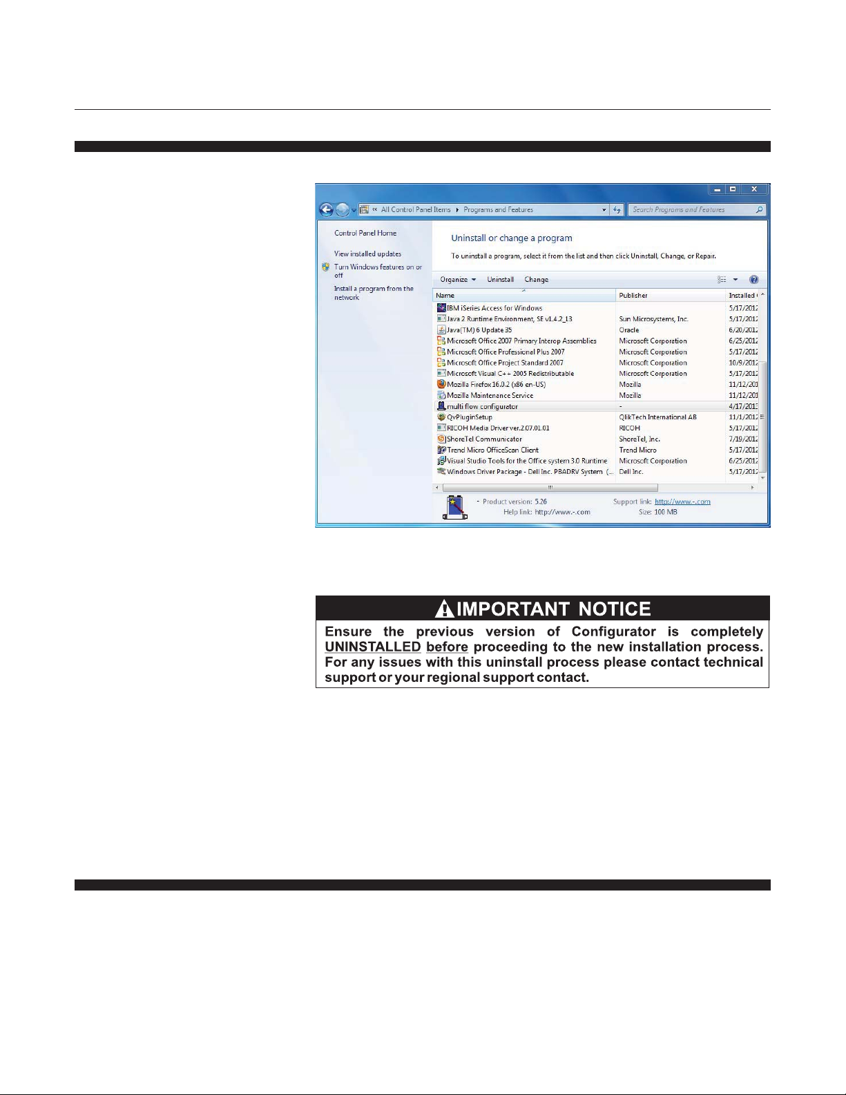
1.3 Uninstall Previous Configurator
1.4 Install the Omega Configurator
1-2
1. If necessary , go to the Control Panel - Add/Remove Programs and
remove any previous version of the Configurator .
Click on Click here for support information to check version number .
Click Remove and follow the remove instructions. Ignore any error
message about failing to unregister a file.
1. Download the latest version of Configurator software and Save it to a
new folder on your computer , e.g., desktop\Omega.
Page 7
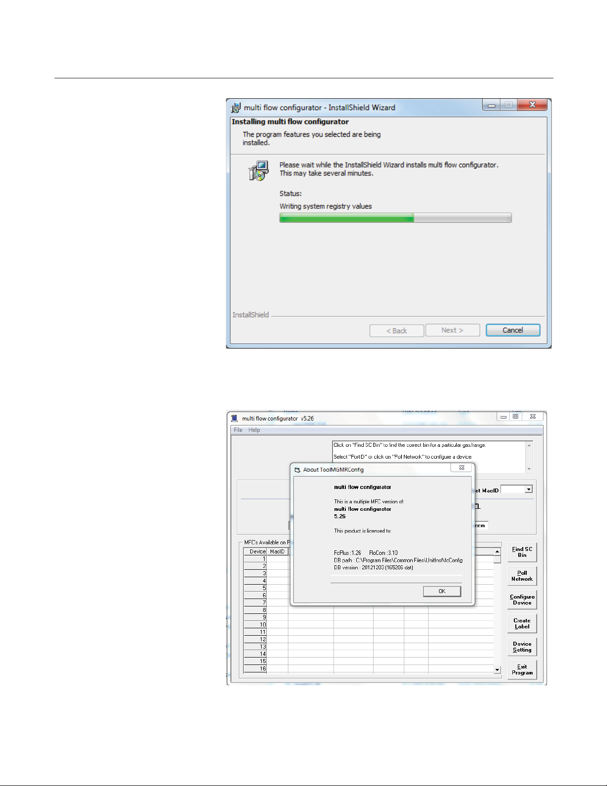
2. Admin privileges required.
Open the folder and run the
installation file:
Multi Flow
Configurator_X_XX_setup.exe.
Where X_XX is the version
number. Click Run when
prompted. Accept the terms of
the license agreement and
accept all other defaults. This
package will also install the
latest Gas Databases. The
software will take up to 5
minutes to install (depending on
the speed of the computer).
Once the installation is
complete the program will
create a shortcut on the
desktop and a program file
menu
Section 1 Installation
FMA-7400/7500 Series Configurator
3. To update the databases open
Configurator software from the
shortcut on the desktop or the
menu Start All Programs
Multi Flow Configurator.
Click Help About. Note the
location of the database files:
C:\Program Files\Common
Files\Unitinst\FcConfig.
For non-English Operating
system the location may be
different from the example.
1-3
Page 8
Section 1 Installation
FMA-7400/7500 Series Configurator
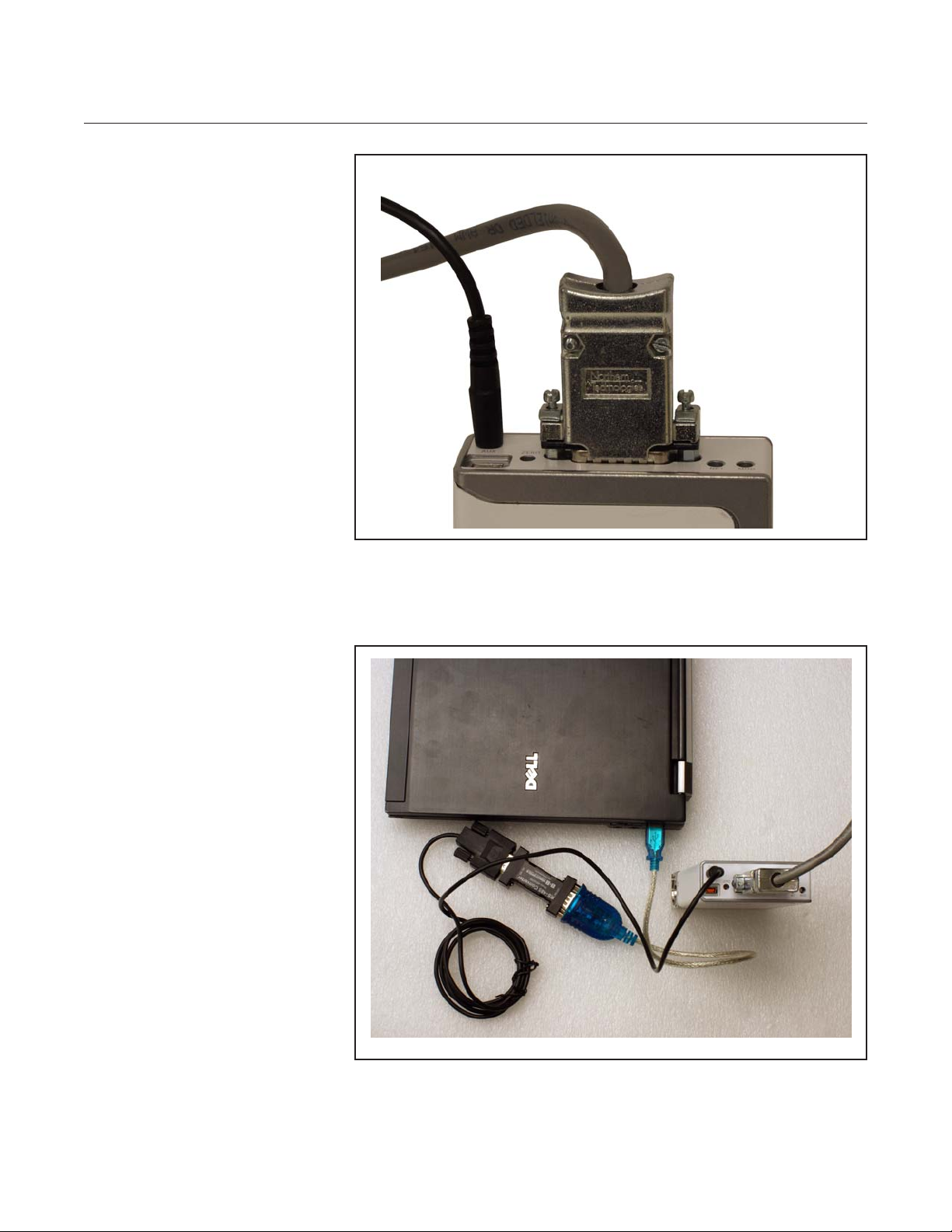
4. To configure a mass flow
device first make all electrical
connections to the device. For
DeviceNet devices use a
standard DeviceNet +24 Vdc
power supply . The Net LED
may indicate red if there is no
terminator on the network. If
there is more than one device
connected then the NET LED
may blink. RS485/D-sub
devices use a ±15 Vdc power
supply . Pins required to be
connected are pins 3 +15
Vdc, 5 -15 Vdc, 4 Power
Common and 7 Signal
Common. URS-20 (now
obsolete) is part of kit FMA745-CK-P. Shown to the right is
the basic RS485 connections.
5. Connect communication cable.
There are various ways to
connect the device regardless
of device configuration. Devices
may be connected through the
diagnostic port using cables in
the Basic Configurator Kit
FMA-745-CK (Cable Assembly
2.5mm and Converter 232/485)
for RS485 communications.
1-4
Page 9
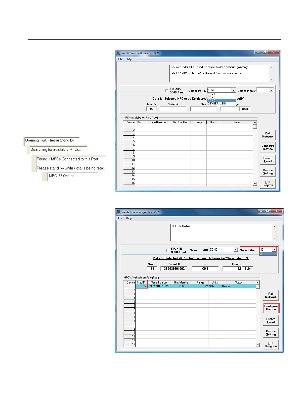
6. From the Configurator main
page select the communication
port used to connect between
the device and PC (Select
PortID). If using a USB-COM
port adapter or USB-RS485
adapter, these must be
connected before starting the
Configurator software. Click
Poll Network. The following
status messages will be
displayed:
Section 1 Installation
FMA-7400/7500 Series Configurator
7. I f there are multiple devices
connected to the bus a short
summary will appear in the
MFCs Available on Port(Tool)
section listed in MacID order.
Select MacID drop down list
box will automatically display
the first available device but
can be changed to any desired
device on the connected bus.
Click on Configure Device to
proceed to the configuration
page.
1-5
Page 10
Section 1 Installation
FMA-7400/7500 Series Configurator
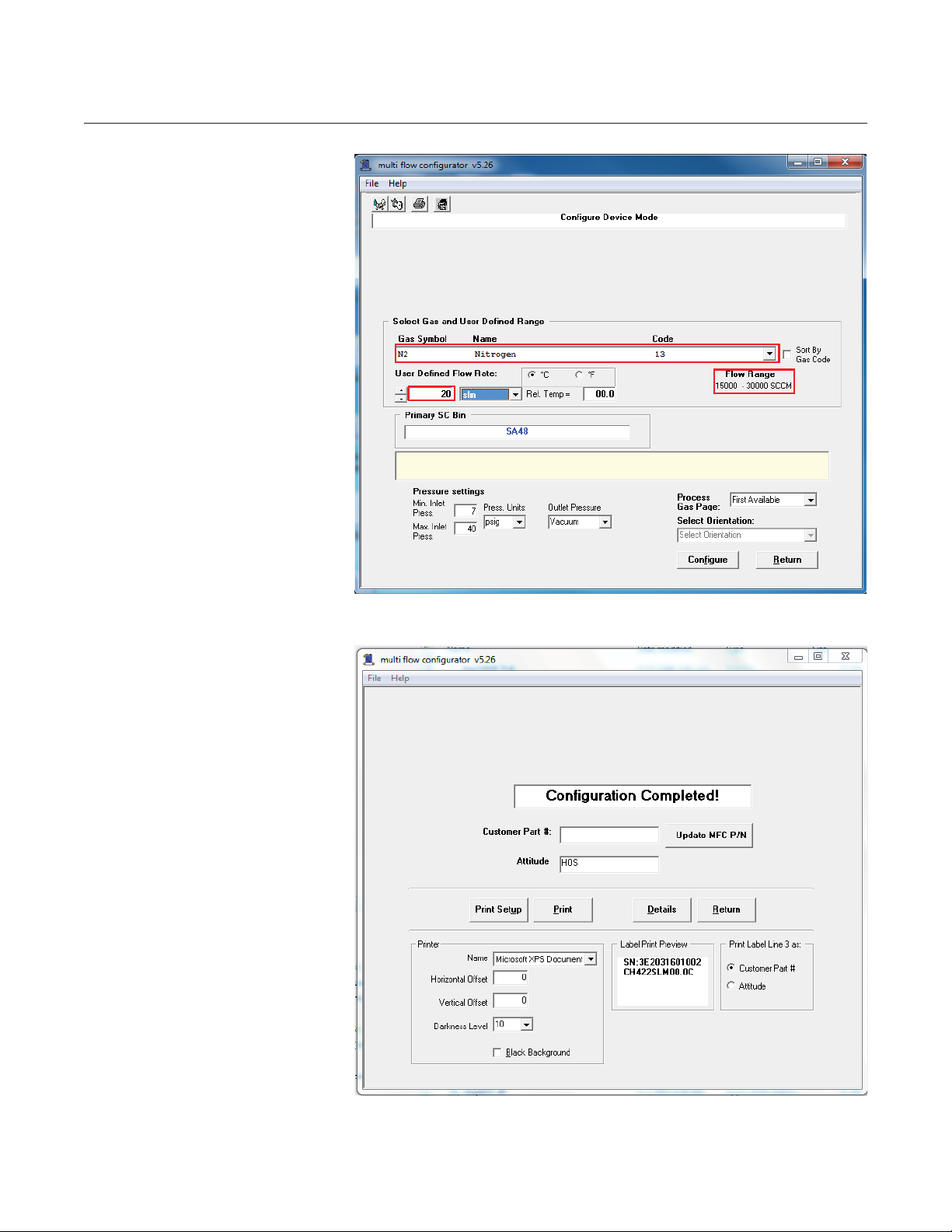
8. In the Select Gas and User
Defined Range section select
the required gas type from the
drop down list.
Enter the required Full Scale
flow for the gas in User
Defined Flow Rate. As you
type the User Defined Flow
Rate the Primary SC Bin value
may change. The user defined
flow range must be within the
flow range on the right hand
side of the screen.
Press Configure to update the
unit with the selected gas
details.
9. As the software reads the
device calibration and writes a
new process gas page to the
device the status will show
progress. When complete the
Configuration Completed
screen will appear . A new
Customer Part Number can
be entered into the unit. Top
Labels can be printed for the
new configuration or you can
view Details of some older
configurations in the device.
When completed click Return
to go back to the Main screen.
The network will be rescanned
to update the scan list.
1-6
Page 11
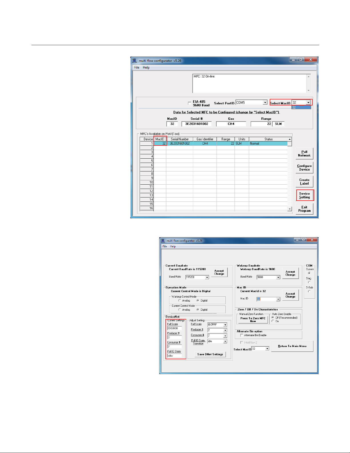
10 To Adjust the DeviceNet or
RS485 settings select Device
Setting from the Main screen.
A Password is required. Enter
cel123 as the password
11. This step is for DeviceNet
devices only .
To view the current DeviceNet
configuration note the Full
Scale, Producer # and
Consumer # settings of the
DeviceNet – Current Settings
section.
To adjust the DeviceNet
settings to match the tool
configuration select DeviceNet
– Adjust Settings
– Full Scale, Producer# and
Consumer#
Common configurations are:
Section 1 Installation
FMA-7400/7500 Series Configurator
1-7
Page 12
Section 1 Installation
FMA-7400/7500 Series Configurator
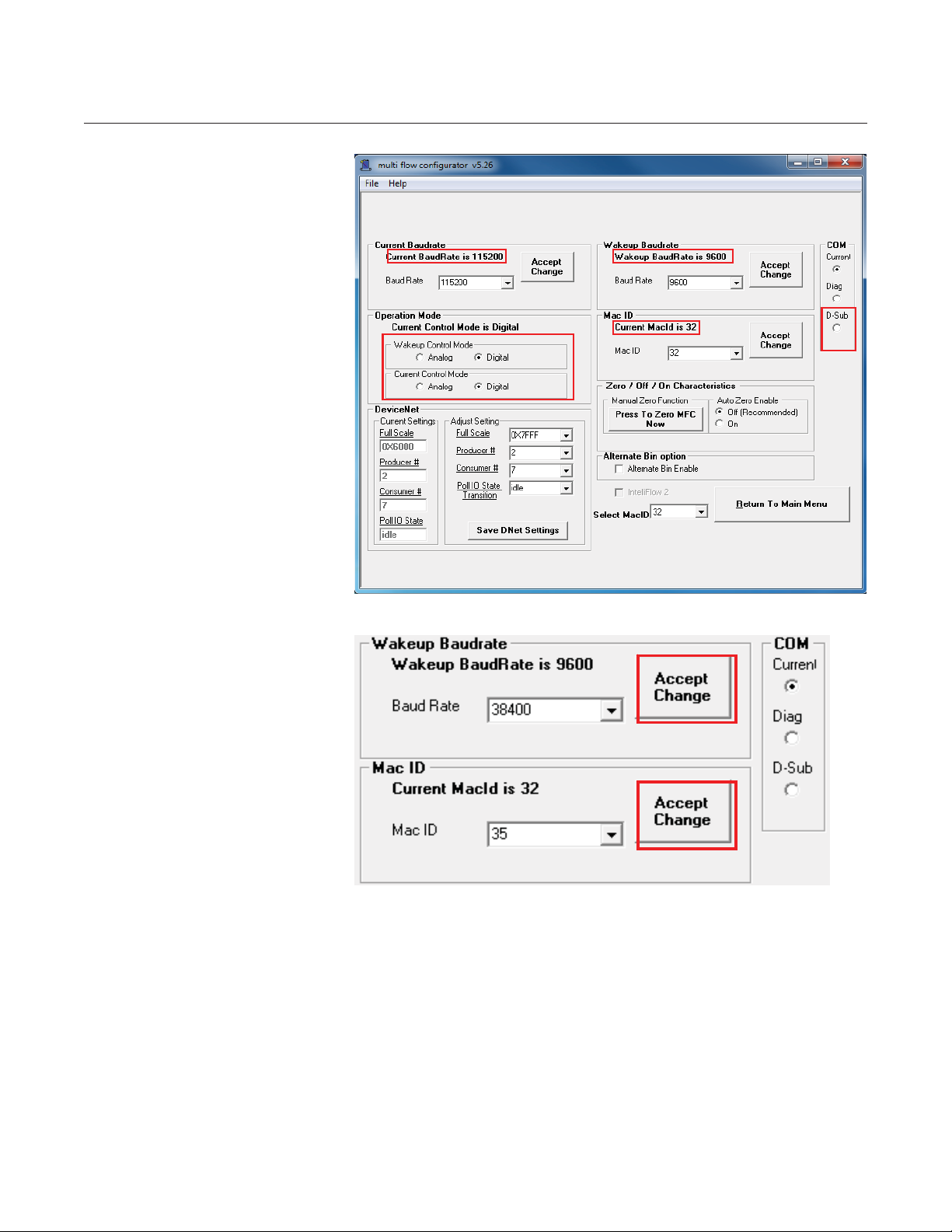
12.To view the current RS485
configuration for the 15 pin
connector select D-sub and
note Current BaudRate,
Wakeup BaudRate, Control
Mode and Mac ID.
13.To configure the mass flow
controller or meter for the most
common RS485 digital
communication settings select:
D-sub,
Wakeup Control Mode =
Digital
Current Control Mode =
Digital
Wakeup Baud Rate-4 = 38400
Mac ID as required by the
position on the gas panel. Click
on the Wakeup BaudRate
Accept Change
button before the Mac ID
Accept Change Button.
If the Wakup Baud Rate is
changed the device must be
repowered for the new settings
to take effect.
If the Mac ID of the currently
connected communication port
is changed the device must be
rescanned to re-establish
communications.
14.If you have any questions
please contact Omega
Engineering T echnical Support.
1-8
Page 13

WARRANTY/DISCLAIMER
OMEGA ENGINEERING, INC. warrants this unit to be free of defects in materials and workmanship for a
period of 13 months from date of purchase. OMEGA’s WARRANTY adds an additional one (1) month
grace period to the normal one (1) year product warranty to cover handling and shipping time. This
ensures that OMEGA’s customers receive maximum coverage on each product.
If the unit malfunctions, it must be returned to the factory for evaluation. OMEGA’s Customer Service
Department will issue an Authorized Return (AR) number immediately upon phone or written request.
Upon examination by OMEGA, if the unit is found to be defective, it will be repaired or replaced at no
charge. OMEGA’s WARRANTY does not apply to defects resulting from any action of the purchaser,
including but not limited to mishandling, improper interfacing, operation outside of design limits,
improper repair, or unauthorized modification. This WARRANTY is VOID if the unit shows evidence of
having been tampered with or shows evidence of having been damaged as a result of excessive corrosion;
or current, heat, moisture or vibration; improper specification; misapplication; misuse or other operating
conditions outside of OMEGA’s control. Components in which wear is not warranted, include but are not
limited to contact points, fuses, and triacs.
OMEGA is pleased to offer suggestions on the use of its various products. However,
OMEGA neither assumes responsibility for any omissions or errors nor assumes liability for any
damages that result from the use of its products in accordance with information provided by
OMEGA, either verbal or written. OMEGA warrants only that the parts manufactured by the
company will be as specified and free of defects. OMEGA MAKES NO OTHER WARRANTIES OR
REPRESENTATIONS OF ANY KIND WHATSOEVER, EXPRESSED OR IMPLIED, EXCEPT THAT OF
TITLE, AND ALL IMPLIED WARRANTIES INCLUDING ANY WARRANTY OF MERCHANTABILITY
AND FITNESS FOR A PARTICULAR PURPOSE ARE HEREBY DISCLAIMED. LIMITATION OF
LIABILITY: The remedies of purchaser set forth herein are exclusive, and the total liability of
OMEGA with respect to this order, whether based on contract, warranty, negligence,
indemnification, strict liability or otherwise, shall not exceed the purchase price of the
component upon which liability is based. In no event shall OMEGA be liable for
consequential, incidental or special damages.
CONDITIONS: Equipment sold by OMEGA is not intended to be used, nor shall it be used: (1) as a “Basic
Component” under 10 CFR 21 (NRC), used in or with any nuclear installation or activity; or (2) in medical
applications or used on humans. Should any Product(s) be used in or with any nuclear installation or
activity, medical application, used on humans, or misused in any way, OMEGA assumes no responsibility
as set forth in our basic WARRANTY/DISCLAIMER language, and, additionally, purchaser will indemnify
OMEGA and hold OMEGA harmless from any liability or damage whatsoever arising out of the use of the
Product(s) in such a manner.
RETURN REQUESTS/INQUIRIES
Direct all warranty and repair requests/inquiries to the OMEGA Customer Service Department. BEFORE
RETURNING ANY PRODUCT(S) TO OMEGA, PURCHASER MUST OBTAIN AN AUTHORIZED RETURN
(AR) NUMBER FROM OMEGA’S CUSTOMER SERVICE DEPARTMENT (IN ORDER TO AVOID
PROCESSING DELAYS). The assigned AR number should then be marked on the outside of the return
package and on any correspondence.
The purchaser is responsible for shipping charges, freight, insurance and proper packaging to prevent
breakage in transit.
FOR WARRANTY
following information available BEFORE
contacting OMEGA:
1. Purchase Order number under which the product
was PURCHASED,
2. Model and serial number of the product under
warranty, and
3. Repair instructions and/or specific problems
relative to the product.
OMEGA’s policy is to make running changes, not model changes, whenever an improvement is possible. This affords
our customers the latest in technology and engineering.
OMEGA is a registered trademark of OMEGA ENGINEERING, INC.
© Copyright 2009 OMEGA ENGINEERING, INC. All rights reserved. This document may not be copied, photocopied,
reproduced, translated, or reduced to any electronic medium or machine-readable form, in whole or in part, without the
prior written consent of OMEGA ENGINEERING, INC.
RETURNS, please have the
FOR NON-WARRANTY REPAIRS,
for current repair charges. Have the following
information available BEFORE contacting OMEGA:
1. Purchase Order number to cover the COST
of the repair,
2. Model and serial number of the product, and
3. Repair instructions and/or specific problems
relative to the product.
consult OMEGA
Page 14

Where Do I Find Everything I Need for
Process Measurement and Control?
OMEGA…Of Course!
Shop online at omega.com
SM
TEMPERATURE
䡺⻬
Thermocouple, RTD & Thermistor Probes, Connectors, Panels & Assemblies
䡺⻬
Wire: Thermocouple, RTD & Thermistor
䡺⻬
Calibrators & Ice Point References
䡺⻬
Recorders, Controllers & Process Monitors
䡺⻬
Infrared Pyrometers
PRESSURE, STRAIN AND FORCE
䡺⻬
Transducers & Strain Gages
䡺⻬
Load Cells & Pressure Gages
䡺⻬
Displacement Transducers
䡺⻬
Instrumentation & Accessories
FLOW/LEVEL
䡺⻬
Rotameters, Gas Mass Flowmeters & Flow Computers
䡺⻬
Air Velocity Indicators
䡺⻬
Turbine/Paddlewheel Systems
䡺⻬
Totalizers & Batch Controllers
pH/CONDUCTIVITY
䡺⻬
pH Electrodes, Testers & Accessories
䡺⻬
Benchtop/Laboratory Meters
䡺⻬
Controllers, Calibrators, Simulators & Pumps
䡺⻬
Industrial pH & Conductivity Equipment
DATA ACQUISITION
䡺⻬
Data Acquisition & Engineering Software
䡺⻬
Communications-Based Acquisition Systems
䡺⻬
Plug-in Cards for Apple, IBM & Compatibles
䡺⻬
Datalogging Systems
䡺⻬
Recorders, Printers & Plotters
HEATERS
䡺⻬
Heating Cable
䡺⻬
Cartridge & Strip Heaters
䡺⻬
Immersion & Band Heaters
䡺⻬
Flexible Heaters
䡺⻬
Laboratory Heaters
ENVIRONMENTAL
MONITORING AND CONTROL
䡺⻬
Metering & Control Instrumentation
䡺⻬
Refractometers
䡺⻬
Pumps & Tubing
䡺⻬
Air, Soil & Water Monitors
䡺⻬
Industrial Water & Wastewater Treatment
䡺⻬
pH, Conductivity & Dissolved Oxygen Instruments
541B167AAO-06-12
M-5297/0513
 Loading...