

Page 1
FMA 5400A/FMA 5500A
Mass Flow Controllers
omega.com
e-mail: [email protected]
For latest product manuals:
omegamanual.info
User’s Guide
Shop online at
Page 2

Servicing North America:
U.S.A.: Omega Engineering, Inc., One Omega Drive, P.O. Box 4047
ISO 9001 Certified
Stamford, CT 06907-0047
Toll-Free: 1-800-826-6342 Tel: (203) 359-1660
FAX: (203) 359-7700 e-mail: [email protected]
Canada: 976 Bergar
Laval (Quebec), Canada H7L 5A1
Toll-Free: 1-800-826-6342 TEL: (514) 856-6928
FAX: (514) 856-6886 e-mail: [email protected]
For immediate technical or application assistance:
U.S.A. and Canada: Sales Service: 1-800-826-6342/1-800-TC-OMEGA
®
Customer Service: 1-800-622-2378/1-800-622-BEST
®
Engineering Service: 1-800-872-9436/1-800-USA-WHEN
®
Mexico: En Español: 001 (203) 359-7803 FAX: (001) 203-359-7807
Servicing Europe:
Benelux: Managed by the United Kingdom Office
Czech Republic: Frystatska 184
733 01 Karviná, Czech Republic
Toll-Free: 0800-1-66342 TEL: +420-59-6311899
FAX: +420-59-6311114 e-mail: [email protected]
France: Managed by the United Kingdom Office
Toll-Free: 0800 466 342 TEL: +33 (0) 161 37 29 00
FAX: +33 (0) 130 57 54 27 e-mail: [email protected]
Germany/Austria: Daimlerstrasse 26
D-75392 Deckenpfronn, Germany
Toll-Free: 0 800 6397678 TEL: +49 (0) 7059 9398-0
FAX: +49 (0) 7056 9398-29 e-mail: [email protected]
United Kingdom: OMEGA Engineering Ltd.
ISO 9001 Certified
One Omega Drive, River Bend Technology Centre, Northbank
Irlam, Manchester M44 5BD England
Toll-Free: 0800-488-488 TEL: +44 (0)161 777-6611
FAX: +44 (0)161 777-6622 e-mail: [email protected]
OMEGAnet®Online Service Internet e-mail
omega.com [email protected]
It is the policy of OMEGA Engineering, Inc. to comply with all worldwide safety and EMC/EMI
regulations that apply. OMEGA is constantly pursuing certification of its products to the European New
Approach Directives. OMEGA will add the CE mark to every appropriate device upon certification.
The information contained in this document is believed to be correct, but OMEGA accepts no liability for any
errors it contains, and reserves the right to alter specifications without notice.
WARNING: These products are not designed for use in, and should not be used for, human applications.
Page 3

TABLE OF CONTENTS
1. UNPACKING THE FMA 5400A/5500A MASS FLOW CONTROLLER......
1.1 Inspect Package for External Damage..............................................
1.2 Unpack the Mass Flow Controller.......................................................
1.3 Returning Merchandise for Repair.....................................................
2. INSTALLATION....................................................................
2.1 Primary Gas Connections.................................................................
2.2 Electrical Connections......................................................................
2.2.1 Valve Control Configuration............................................
2.2.2 Remote LCD Readouts...................................................
2.2.3 Panel Mounting Readouts..............................................
3. PRINCIPLE OF OPERATION....................................................
4. SPECIFICATIONS..................................................................
4.1 CE Compliance................................................................................
4.2 Flow Capacities................................................................................
5. OPERATING INSTRUCTIONS...................................................
5.1 Preparation and Warm Up................................................................
5.2 Flow Signal Output Readings..............................................................
5.3 Swamping Condition...........................................................................
5.4 Setpoint Reference Signal..................................................................
5.5 Valve OFF Control (Open Collector NPN Compatible)..........................
5.6 Valve Test/Purge.................................................................................
6. MAINTENANCE....................................................................
6.1 Introduction........................................................................................
6.2 Flow Path Cleaning..............................................................................
6.2.1 Cleaning the Inlet Filter Screen in FMA Models.................
6.2.2 Valve Maintenance for FMA 5400A/5500A
Series Max. Flow 10, 50 and 100 L/min............................
7. CALIBRATION PROCEDURES....................................................
7.1 Flow Calibration...................................................................................
7.2 Calibration of FMA 5400A/5500A Series Max. Flow 10, 50
and 100 L/min..................................................................................
7.2.1 Connections and Initial Warm Up...................................
7.2.2 Zero Adjustment.............................................................
7.2.3 SPAN Adjustment...........................................................
7.2.4 Linearity Adjustment......................................................
1
1
1
1
2
2
2
5
6
6
7
7
10
10
11
11
12
12
13
14
14
15
15
15
15
16
18
18
19
19
20
20
20
20
Page 4

7.2.4.1 Disable Solenoid Valve in FMA 5400A/5500A
Series Max. Flow 10, 50 and 100 L/min............................
7.2.5 Connections and Initial Warm Up..................................
7.2.6 ZERO Adjustment..........................................................
7.2.7 25% Flow Adjustment Using R33 Potentiometer............
7.2.8 10% Flow Adjustment.....................................................
7.2.9 25% Flow Adjustment (using R52 potentiometer).........
7.2.10 50% Flow Adjustment....................................................
7.2.11 75% Flow Adjustment.......................................................
7.2.12 100% Flow Adjustment..................................................
7.2.13. Valve adjustment.............................................................
7.2.13.1 Valve Adjustment for Series Max. Flow 10, 50, 100 L/min........
7.2.14 Close Loop Full Scale Flow Adjustment...........................
7.2.15 10% Close Loop Flow Adjustment
(using R33 potentiometer).............................................
7.2.16 25% Close Loop Flow Adjustment
(using R52 potentiometer).............................................
7.2.17 Close Loop 25% Flow Adjustment
(using R33 potentiometer).............................................
7.2.18 Close Loop 50% Flow Adjustment....................................
7.2.19 Close Loop 75% Flow Adjustment...................................
7.2.20 Close Loop 100% Flow Adjustment...................................
7.3 Calibration of FMA 5400A/5500A
Series Max. Flow 200, 500 and 1000 L/min....................
7.3.1 Connections and Initial Warm Up...................................
7.3.2 ZERO Adjustment................................................................
7.3.3 SPAN Adjustment.............................................................
7.3.4 Linearity Adjustment.......................................................
7.3.4.1 Open Motorized Valve in FMA 5400A/5500A
Series Max. Flow 200, 500 and 1000 L/min....................
7.3.5 Connections and Initial Warm Up...................................
7.3.6 ZERO Adjustment............................................................
7.3.7 25% Flow Adjustment.........................................................
7.3.8 50% Flow Adjustment.....................................................
7.3.9 75% Flow Adjustment.....................................................
7.3.10 100% Flow Adjustment.....................................................
7.3.11. Valve adjustment..............................................................
7.3.11.1 Valve Adjustment for FMA 5400A/5500A
Series Max. Flow 200, 500 and 1000 L/min....................
7.3.12 Full Scale Flow Adjustment.................................................
7.3.13 25% Flow Adjustment.....................................................
7.3.14 50% Flow Adjustment........................................................
20
21
21
21
22
22
22
22
22
23
23
23
23
23
23
24
24
24
24
25
25
25
26
26
26
26
26
27
27
27
27
27
28
28
28
Page 5

7.3.15 75% Flow Adjus7.3.16 100% Flow Adjustment.............
7.4 LCD Display Scaling.........................................................
7.4.1 Access LCD Display Circuit..............................................
7.4.2 Adjust Scaling..................................................................
7.4.3 Change Decimal Point.....................................................
8. TROUBLESHOOTING.............................................................
8.1 Common Conditions...........................................................................
8.2 General Troubleshooting Guide.........................................................
8.3 FMA 5400A/5500A Series Max. Flow 10, 50 and 100 L/min
Valve Related Troubleshooting.........................................................
8.4 Technical Assistance.........................................................................
9. CALIBRATION CONVERSIONS FROM REFERENCE GASES................
APPENDIX 1 COMPONENT DIAGRAM..................................................
APPENDIX 2 GAS FACTOR TABLE (“K” FACTORS)...............................
APPENDIX 3 DIMENSIONAL DRAWINGS.............................................
APPENDIX 4 WARRANTY......................................................................
28
28
28
29
29
29
29
30
32
35
35
36
38
42
46
Page 6

1
1. UNPACKING THE FMA 5400A/5500A
MASS FLOW CONTROLLER
1.1 Inspect Package for External Damage
Your FMA 5400A/5500A Mass Flow Controller was carefully packed in a sturdy
cardboard carton, with anti-static cushioning materials to withstand shipping
shock. Upon receipt, inspect the package for possible exter nal damage. In case
of external damage to the package contact the shipping company immediately.
1.2 Unpack the Mass Flow Controller
Open the carton carefully from the top and inspect for any sign of concealed shipping damage. In addition to contacting the shipping carrier please forward a copy
of any damage report to OMEGA
®
directly.
When unpacking the instrument please make sure that you ha ve all the items indicated on the Packing List. Please report any shortages promptly.
1.3 Returning Merchandise for Repair
Please contact an OMEGA
®
customer service representative and request a
Return Authorization Number (AR).
It is mandatory that any equipment returned for servicing be purged and neutralized of any dangerous contents including but not limited to toxic, bacterially infectious, corrosive or radioactive substances. No work shall be performed on a
returned product unless the customer submits a fully executed, signed SAFETY
CERTIFICATE. Please request form from the Service Manager.
CAUTION: Some of the IC devices used in the FMA 5400A/5500A are
Electro Static Discharge (ESD) sensitive and may be damaged by
improper handling. When wiring the interface connector, adjusting or
servicing the meter, use of a grounded ESD protection wrist strap is
required to prevent inadver tent damage to the CMOS integral solid
state circuitry. When 15 pins inter face D-connector is not used do not
remove factor y installed ESD protection cover.
Page 7

2. INSTALLATION
2.1 Primary Gas Connections
Please note that the FMA 5400A/5500A Mass Flow Controller will not operate
with liquids. Only clean gases are allowed to be introduced into the instrument.
Contaminated gases must be filtered to prevent the introduction of impediments
into the sensor.
CAUTION: It is the users responsibility to determine if the instr ument is
appropriate for their OXYGEN application, and for specifying O2
cleaning service if required. OMEGA is not liable for any damage or
personal injury, whatsoever, resulting from the use of this instr ument
for oxygen gas.
Attitude sensitivity of the Mass Flow Controller is ±15
F
. This means that the gas
flow path of the flow meter must be horizontal within those stated limits. Should
there be need for a different or ientation of the meter, re-calibration may be necessary. It is also preferable to install the FMA 5400A/5500A transducer in a stable environment, free of frequent and sudden temperature changes, high moisture, and drafts.
Prior to connecting gas lines inspect all parts of the piping system including ferrules and fittings for dust or other contaminants. Be sure to observe the direction
of gas flow as indicated by the arrow on the front of the meter when connecting
the gas system to be monitored.
Insert tubing into the compression fittings until the ends of the properly sized tubings home flush against the shoulders of the fittings. Compression fittings are to
be tightened according to the manufacturer's instructions to one and one quarter
turns. Avoid over tightening which will seriously damage the Restrictor Flow
Elements (RFE's)!
Compression fittings should not be removed unless the meter is being cleaned or
calibrated for a new flow range.
Using a Helium Leak Detector or other equivalent method perform a thorough
leak test of the entire system.
(All FMA 5400A/5500A’s are checked prior to ship-
ment for leakage within stated limits. See specifications in this manual.)
2.2 Electrical Connection
2
CAUTION: Some of the IC devices used in the FMA 5400A/5500A are
Electro Static Discharge (ESD) sensitive and may be damaged by
improper handling. When wiring the interface connector, adjusting or
servicing the meter, use of a grounded ESD protection wrist strap is
required to prevent inadver tent damage to the CMOS integral solid
state circuitry. When 15 pins interface D-connector is not used do not
remove factor y installed ESD protection cover.
Page 8

Base on the FMA 5400A/5500A transducers model number it may
require different power supply voltage: ether 12Vdc, 24Vdc or
universal (any voltage between 12 and 26 Vdc). Before connecting
power supply check controller power supply requirements label
located on the controller back cover. If power supply requirements
label states that power supply requirements is 12 Vdc, do not
connect power supply with voltage above 15 Vdc. Exceeding
specified maximum power supply voltage limit will result in device
permanent damage.
The operating power input is supplied via the 15-pin “D” connector located at the
side of the flow transducer enclosure. On FMA 5400A/5500A's purchased without
an LCD readout, a readout panel meter, digital multimeter, or other equivalent
device is required to facilitate visual flow readings.
A built in SETPOINT potentiometer is used for local control of the flow. Variable
analog 0 to 5 Vdc (or 4 to 20 mA) reference input is required for remote control.
3
CAUTION: WIRING THE FMA 5400A/5500A METER OR CHANGING
NJ1 JUMPERS CONFIGURATION WITH THE POWER ON MAY
RESU LT IN INTERNAL DAMAGE! PLEASE MAKE ALL WIRING
CONNECTIONS AND N J1 J UM PE R S I N STALLATIONS BEFORE
SWITCHING ON THE POWER.
Page 9
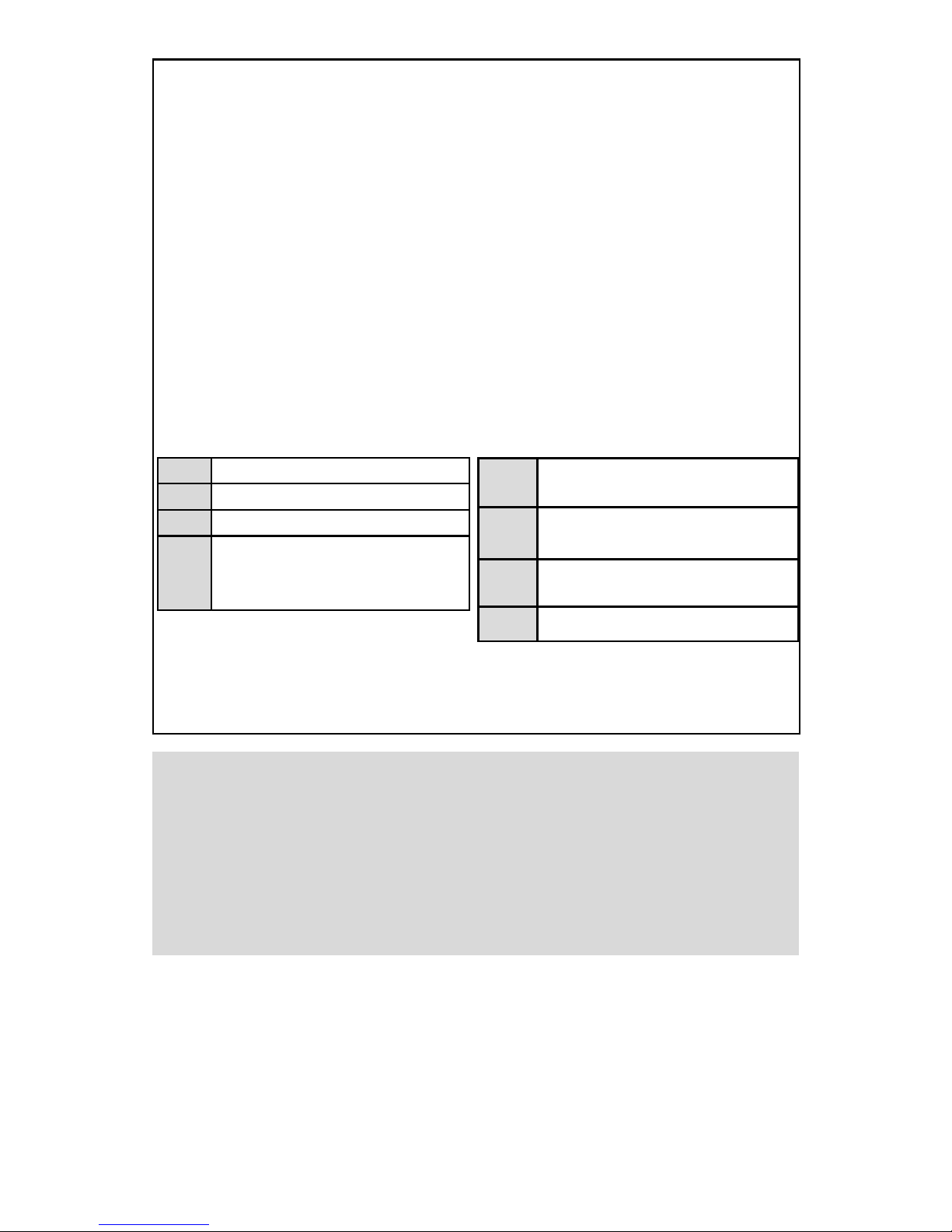
4
PIN FUNCTION
1 0 to 5 VDC Flow Signal Common
2 0 to 5 VDC Flow Signal Output
3 Common
4 Open (Purge)
5 Common, Power Supply
6 (unassigned)
7 +12 VDC (Optional +24 VDC*) Power Supply
8 Remote Setpoint Input
9 4 to 20 mA (-) Flow Signal Return (use with 14)
10 Remote Setpoint Common (use with 8)
11 +5VDC Reference Output for Remote Setpoint
12 Valve Off Control
13 Auxiliary +12 VDC (Optional +24 VDC*)
Power Output (For Loads <100 mA)
14 4 to 20 mA (+) Flow Signal Output
15 Chassis Ground
FIGURE 2-1 FMA 5400A/5500A 15-PIN “D” CONNECTOR CONFIGURATION
*Do not connect +24 Vdc power supply unless your FMA 5400A/5500A controller was
ordered and configured for 24 Vdc
1 & 2 0-5 Vdc OUTPUT
3 & 4 PURGE
3 & 12 VALVE OFF CONTROL
5 & 13
AUXILIARY +12 Vdc (Optional +24
Vdc*) POWER OUTPUT (FOR LOADS
<100 mA)
CAUTION: BEFORE CONNECTING THE POWER SUPPLY CHECK
YOUR CONTROLLER MODEL NUMBER AND POWER SUPPLY
REQUIREMENTS LABEL LOCATED ON THE CONTROLLER BACK
COVER. DO NOT CONNECT 24 Vdc POWER SUPPLY UNLESS
YOUR FMA 5400A/5500A CONTROLLER WAS ORDERED AND
CONFIGURED FOR 24 Vdc. EXCEEDING THE SPECIFIED
MAXIMUM POWER SUPPLY VOLTAGE LIMIT MAY RESULT IN
PERMANENT DEVICE DAMAGE.
Important notes:
In general, “D” Connector numbering patter ns are standardized. There are, however, some connectors with nonconforming patterns and the numbering
sequence on your mating connector may or may not coincide with the numbering
sequence shown in our pin configuration table above. It is imperative that you
match the appropriate wires in accordance with the correct sequence regardless
of the particular numbers displayed on your mating connector.
5 & 7
+12 Vdc (Optional +24 Vdc*) POWER
SUPPLY
8 & 10
0-5 Vdc OR 4-20 mA (FROM 3 WIRE LOOP
SOURCING DEVICE) REMOTE SETPOINT
9 & 14
4-20 mA OUTPUT (SOURCING, ONLY
FOR PASSIVE LOAD)
10 & 11 +5 Vdc CONTROL SOURCE
Page 10
5
Po wer must be turned OFF when connecting or disconnecting any cab les in the system.
The power input is protected by a 900mA (FMA 5400/5500 Series Max. Flow 10,
50, 100 L/min) or 1600mA (FMA 5400A/5500A Series Max. Flow 200, 500 and
1000 L/min) M (medium time-lag) resettable fuse. If a shor ting condition or polarity reversal occurs, the fuse will cut power to the flow transducer circuit. Disconnect
the power to the unit, remov e the f aulty condition, and reconnect the po wer. The fuse
will reset once the faculty condition has been removed.
Use of the FMA 5400A/5500A flow transducer in a manner other than that specified in this
manual or in writing from OMEGA
®
, may impair the protection provided b y the equipment.
CAUTION: Fuse will not protect controller if power supply voltage
exceeds maximum voltage specified for a particular model.
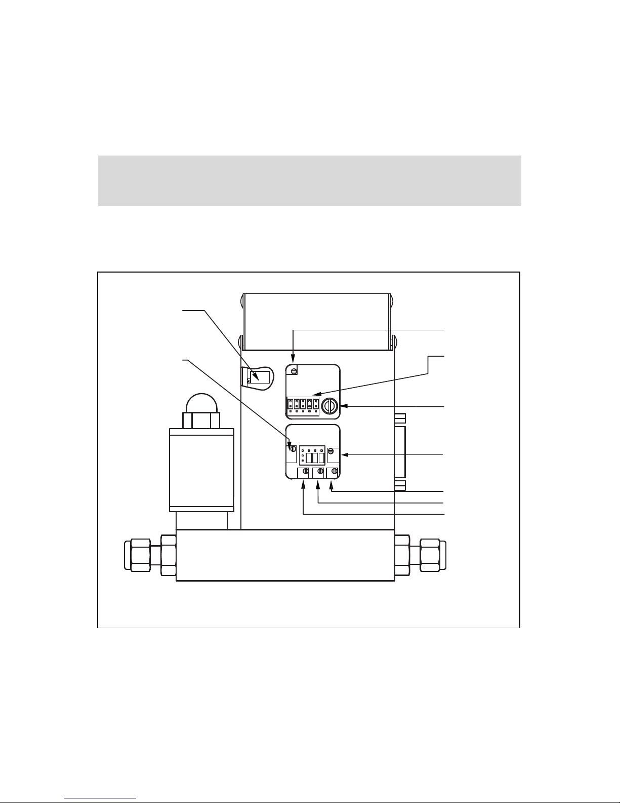
NR7
LOCAL SET POINT
POTENTIOMETER
R34 ZERO
POTENTIOMETER
R38 50%
R39 75%
R40 100%
R33
SPAN (10 or 25%)
R1 RESPONSE
TIME AJUSTMENT
NJ1 CONTROL
CIRCUT JUMPERS
R52 10 or 25 %
FIGURE 2-2, POTENTIOMETER AND JUMPER LOCATIONS
2.2.1 Valve Control Configuration
There are three basic valve control options.
(a) LOCAL or REMOTE control.
(b) 0 to 5 VDC or 4 to 20 mA setpoint signal -
*Note: this only applies for the REMOTE control configuration;
(c) 2% cutoff active or not active. Note: 2% cutoff not available for FMA 200, 500 and
1000 L/min.
Page 11
6
2.2.2 Remote LCD Readouts
FMA 5400A/5500A Mass Flow Controllers are available with optional remote
reading LCD displays supplied with a three foot long wire to accommodate most
applications. This configuration includes the upper bloc k element which serves as
the LCD readout mounting. Special lengths of remote extension wiring (up to 9.5
feet [3 meters] are available on request.
2.2.3 Panel Mounting Readouts
Another option for the FMA 5400A/5500A Mass Flow Controller is the Panel
Mounting Remote Readout.
In this configuration the LCD readout is supplied with a three foot long extension
wire, and no aluminum housing around the LCD. The LCD readout for panel
mounting includes a bezel with two plastic screws which con veniently fit into a rectangular cut-out for panel mounting (see Figure 2-3).
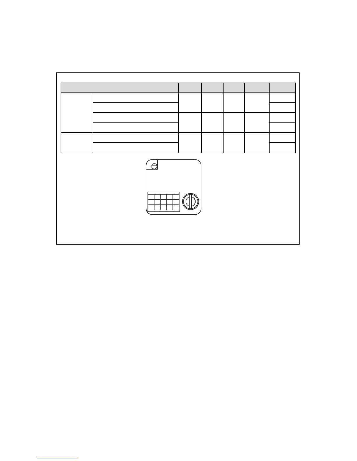
When active, the 2% cutoff will shut off the power to the valve when a setpoint of
less than 2% of the full scale flow range is set. Figure 2-2 shows the jumper configurations for the three basic valve control options.
The factory default jumper settings are: LOCAL control, 2% cutoff off , and 0 to 5 VDC.
FUNCTION NJ1A NJ1B NJ1C NJ1D NJ1E
Remote
0 to 5 Vdc 2% cutoff ON
2 - 3 5 - 6 8 - 9 10 - 11
13 - 14
0 to 5 Vdc 2% cutoff OFF
14 -15
4 to 20 mA 2% cutoff ON
1 - 2 4 - 5 7 - 8 10 - 11
13 - 14
4 to 20 mA 2% cutoff OFF
14 - 15
Local
2% cutoff ON
2 - 3 5 - 6 8 - 9 11 - 12
13 -14
2% cutoff OFF
14 - 15
3
6 9 12 15
2581114
1 4 7 10 13
ABCDE
FIGURE 2-3, VALVE CONTROL CONFIGURATION JUMPERS
Page 12
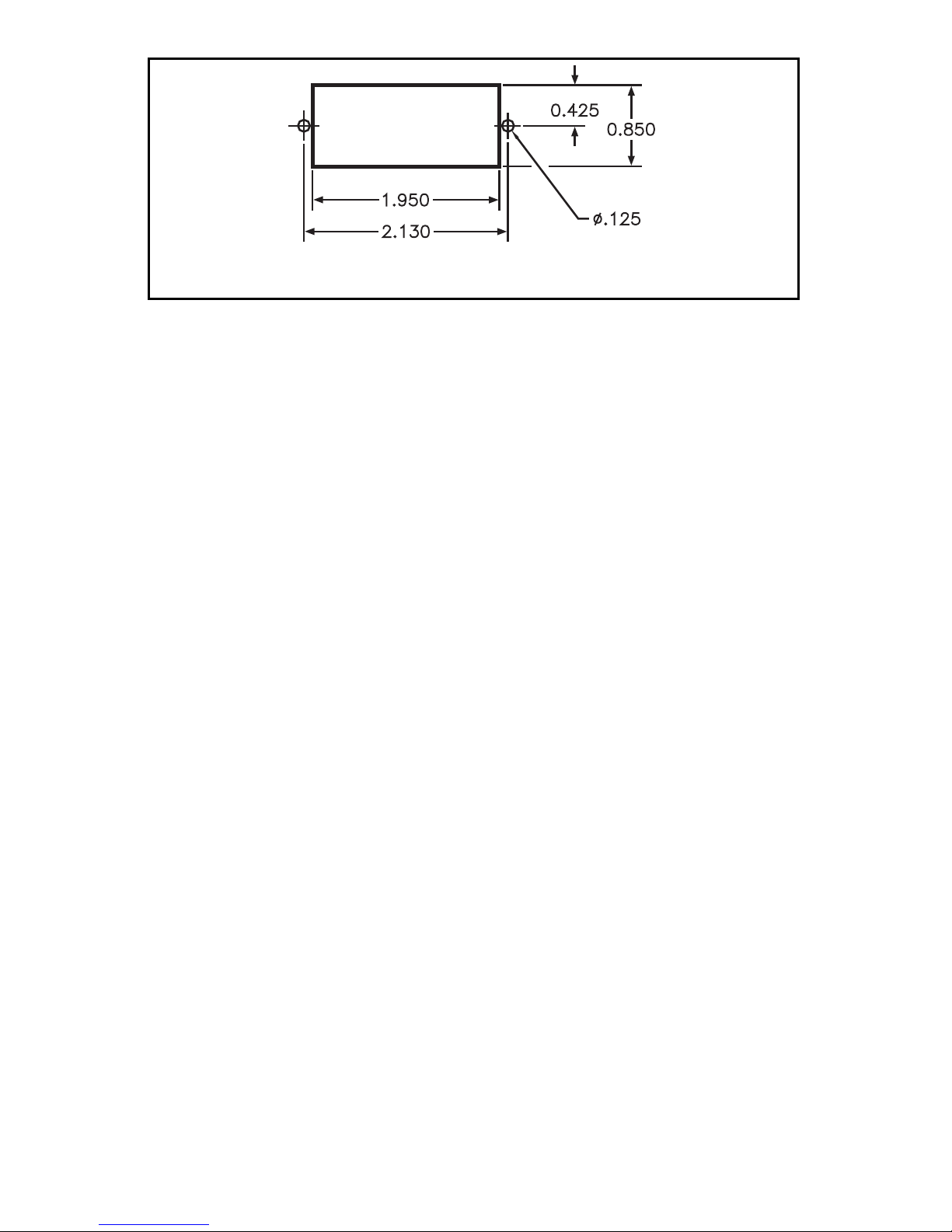
FIGURE 2-4 CUTOUT DIMENSIONS FOR LCD PANEL MOUNTING
3. PRINCIPLE OF OPERATION
The stream of gas entering the Mass Flow transducer is split by shunting a small
portion of the flow through a capillary stainless steel sensor tube. The remainder
of the gas flows through the primary flow conduit. The geometry of the pr imary
conduit and the sensor tube are designed to ensure laminar flow in each branch.
According to principles of fluid dynamics flow rates of gas in two properly sized
laminar flow conduits are related to one another. Therefore, the flow rates measured in the sensor tube are directly proportional to the total flow through the transducer.
In order to sense the flow in the sensor tube, heat flux is introduced at two sections of the sensor tube by means of precision wound heater-sensor coils. Heat
is transferred through the thin wall of the sensor tube to the gas flowing inside. As
gas flow takes place heat is carried by the gas stream from the upstream coil to
the downstream coil windings. The resultant temperature dependent resistance
differential is detected electronically. The measured gradient at the sensor windings is linearly proportional to the instantaneous rate of flow taking place.
An output signal is generated that is a function of the amount of heat carried by
the gases to indicate mass-molecular based flow rates.
FMA 5400A/5500A Mass Flow Controller Series Max. Flow 10, 50 and 100 L/min
also incorporate a propor tionating solenoid valve and Series Max. Flow 200, 500
and 1000 L/min a motorized valve. The closed loop control circuit of the FMA
5400A/5500A continuously compares the mass flow output with the selected flow
rate. Deviations from the setpoint are corrected by compensating valve adjustments, thus maintaining the desired flow parameters.
4. SPECIFICATIONS
FLOW MEDIUM: Please note that FMA 5400A/5500A Mass Flow Controllers are designed
to work with clean gases only. Never try to meter or control flow rates of liquids.
CALIBRATIONS: Supplied at Standard Conditions (14.7 psia and 70
F
F), or Normal
Conditions (0
F
C and 1.01 bar abs) unless otherwise requested or stated.
ENVIRONMENTAL (per IEC 664): Installation Level II; Pollution Degree II.
7
Page 13
8
REPEATABILITY: ±0.5% of full scale.
TEMPERATURE COEFFICIENT: 0.15% of full scale/
F
C.
PRESSURE COEFFICIENT: 0.01% of full scale/psi (0.07 bar).
RESPONSE TIME: FMA 5400A/5500A Series Max. Flow 10 L/min: 300ms time
constant; approximately 1 second to within ±2% of set flow rate for
25% to 100% of full scale flow.
FMA 5400A/5500A Series Max. Flow 50 & 100 L/min: 600ms time
constant; approximately 2 seconds to within ±2% of set flow rate for
25% to 100% of full scale flow.
FMA 5400A/5500A Series Max. Flow 200, 500 & 1000 L/min:
1800ms time constant; approximately 5 seconds to within ± 2% of
set flow rate for 25% to 100% of full scale flow.
MAX GAS PRESSURE: 1000 psig (69 bars) FMA 5400A/5500A Series Max. Flow 10, 50 and
100 L/min; 500 psig (34.5 bars) Series Max. Flow 200, 500 & 1000 L/min. Optimum pressure
is 20 psig (1.4 bars).
TURNDOWN RATIO: 40:1.
MAX DIFFERENTIAL PRESSURE: 50 psid (345 kPa) for 5400A/5500A 10/50/200/500/1000
AND 40 psid (276 kPa) for 5400A/5500A 100.
GAS TEMPERATURE: 32
F
F to 122 FF (0 FC to 50 FC).
AMBIENT TEMPERATURE: 14
F
F to 122 FF (-10 FC to 50 FC).
GAS RELATIVE HUMIDITY: Up to 70%.
MAXIMUM INTERNAL LEAK: 0.5% FS.
LEAK INTEGRITY: 1 x 10
-9
sccs He max to the outside environment.
ACCURACY: FMA 5400/5500 Series Max. Flow 10, 50, 100 L/min: ±1.0% F.S.
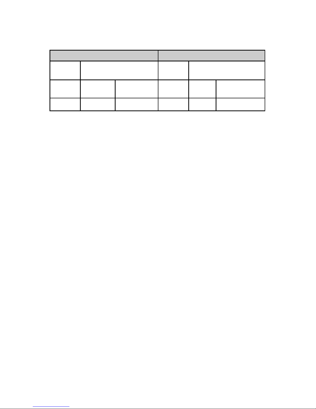
FMA 5400A/5500A Series Max. Flow 200, 500 and 1000 L/min: See table below.
ACCURACY % FS OPTIONAL ENHANCED ACCURACY % FS
MODEL
FMA 5400A/5500A Series Max.
Flow 200, 500 and 1000 L/min
MODEL
FMA 5400A/5500A Series Max.
Flow 200, 500 and 1000 L/min
FLOW
RANGE
20-100%
0-20%
FLOW
RANGE
20-100%
0-20%
ACCURACY ±1.5%
±3%
ACCURACY
±1%
REF DATA with ±1%
Page 14

9
ATTITUDE SENSITIVITY: No greater than ±15 degree rotation from horizontal to vertical;
standard calibration is in horizontal position.
OUTPUT SIGNALS: Linear 0 to 5 VDC (1000 Ω minimum load impedance) and 4 to 20
mA (0 to 500 Ω loop resistance, sourcing only for passive load); 20 mV peak to peak max
noise for FMA 10, 50 and 100 L/min and 100 mV peak to peak max noise for FMA 200,
500 and 1000 L/min.
COMMAND SIGNAL: Analog 0 to 5 VDC (100 KΩ input impedance) or 4 to 20 mA (0 to
250 Ω input impedance, use only with 3 wire 4-20 mA loop sourcing device). Contact
OMEGA
®
for optional RS232 or IEEE488 interfaces.
TRANSDUCER INPUT POWER:
FMA 5400A/5500A Series Max. Flow 200, 500 and 1000 L/min:
Models with 12 Vdc power input: 12 Vdc, 800 mA maximum;
FMA 5400A/5500A Series Max. Flow 200, 500 and 1000 L/min:
Models with 24 Vdc power input: 24 Vdc, 800 mA maximum;
FMA 5400A/5500A Series Max. Flow 10, 50, 100 L/min:
Models with universal power input:
any voltage between +12 and +26 Vdc, 650 mA maximum;
WETTED MATERIALS:
FMA 5400A/5500A Series Max. Flow 10, 50, 100, 200, 500 and 1000 L/min:
Anodized aluminum, brass, 416 Stainless Steel and 316 stainless steel with FKM
O-rings seals; BUNA, EPR or Perflouroelastomer O-rings are optional.
FMA 5400AST/5500AST Series Max. Flow 10, 50, 100, 200, 500 and 1000 L/min:
416 Stainless Steel and 316 stainless steel with FKM O-rings seals; BUNA, EPR or
Perflouroelastomer O-rings are optional.
OMEGA
®
makes no expressed or implied guarantees of corrosion resistance of mass flow
meters as pertains to different flow media reacting with components of meters. It is the
customers sole responsibility to select the model suitable for a particular gas based on the
fluid contacting (wetted) materials offered in the different models.
INLET AND OUTLET CONNECTIONS:
FMA Series Max. Flow 10 and 50 L/min: 1/4" compression fittings.
Optional: 6mm compression, 1/4" VCR
®
,
3/8" or 1/8" compression fittings.
FMA Series Max. Flow 100 and 200 L/min: 3/8"compression fittings.
FMA Series Max. Flow 500 L/min: 1/2" compression fittings.
FMA Series Max. Flow 1000 L/min: 3/4" FNPT ports.
Optional: 3/4" compression fittings.
LCD DISPLAY: 3½ digit LCD (maximum viewable digits “1999”, 0.5 inch high characters.
On FMA 5400A/5500A aluminum or stainless steel models the LCD display is built into the
Page 15
10
Table III
High Flow
Mass Flow Controller*
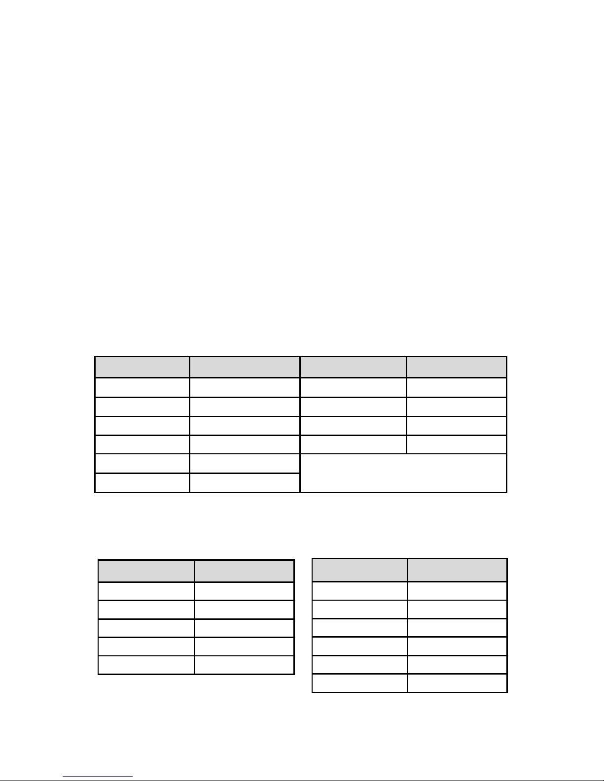
4.2 Flow Capacities
Ta ble I
Low Flow
Mass Flow Controller*
Ta ble I I
Medium Flow
Mass Flow Controller*
* Flow rates are stated for Nitrogen at STP conditions [i.e. 70 FF (21.1 FC) at 1 atm].
For other gases use the K factor as a multiplier from APPENDIX 2.
CODE
mL/min [N2]
CODE
liters/min [N2]
02 0 to 10 14 0 to 1
04 0 to 20 16 0 to 2
06 0 to 50 18 0 to 5
08 0 to 100 20 0 to 10
10 0 to 200
12 0 to 500
4.1 CE Compliance
FMA 5400A/5500A Mass Flow Controllers are in compliance with CE test standards stated below:
EMC Compliance with 89/336/EEC as amended; Emission Standard: EN
55011:1991, Group 1, Class B Immunity Standard: EN 55082-1:1992.
CODE
liters/min [N2]
23 15
24 20
26 30
27 40
28 50
CODE
liters/min [N2]
40
60
41
80
42
100
43
200
44
500
45
1000
upper block element and may be tilted over 90 degrees for optimal viewing comfort.
Remote or panel mounting remote reading is optional. Standard readings are in direct engineering units for the given gas and flow rate (i.e. liters/minute [slpm], standard cubic centimeters/minute [sccm], standard cubic feet/hour [scfh], etc.). 0 to 100% LCD calibration
scaling is available upon request at time of order. Contact OMEGA
®
when non-standard dis-
play settings are desired.
TRANSDUCER INTERFACE CABLE: Optional shielded cable is available mating to the FMA
5400A/5500A transducer 15-pin “D” connector.
Page 16
5. OPERATING INSTRUCTIONS
5.1 Preparation and Warm Up
It is assumed that the Mass Flow Controller has been correctly installed and thoroughly leak tested as described in section (2). Shut the flow source OFF. Apply
power to the unit via the 15-pin “D” connector. Before connecting the power supply check the controller power supply requirements label located on the controller
back cover. If the power supply requirements label states that power supply
requirement is 12 Vdc, do not connect the power supply with voltage above 15
Vdc. Exceeding the specified maximum power supply voltage limit will result in
device permanent damage. Allow the Mass Flow Controller to warm-up for at
least 15 minutes.
During initial powering of the FMA 5400A/5500A transducer, the flow output signal will be indicating a higher than usual output. This is indication that the FMA
5400A/5500A transducer has not yet attained it's minimum operating temperature. This condition will automatically cancel within a few minutes and the transducer should eventually zero.
If after the 15 minutes warm-up period, the display still indicates a reading of less
than ± 3.0 % of F.S., readjust the ZERO potentiometer [R34] through the access
window. Before zero adjustment to temporarily disconnect the gas source, to
ensure that no seepage or leak occurs in to the meter.
11
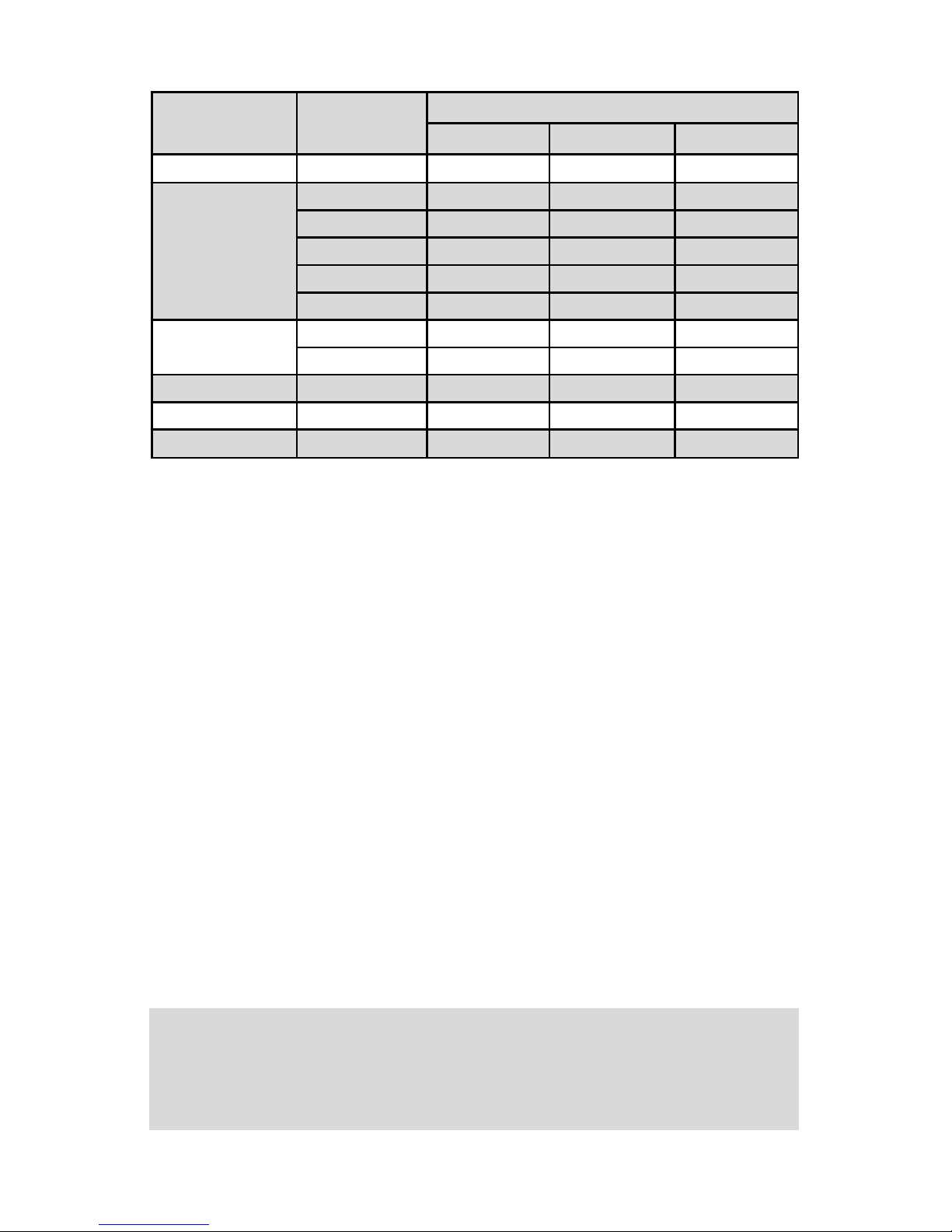
TABLE I PRESSURE DROPS
MAXIMUM FLOW
RATE SERIES
FLOW RATE
[liters/min]
MAXIMUM PRESSURE DROP
[mm H2O]
[psid]
[mbar]
10 L/min up to 10 720 1.06 75
50 L/min
15 2630 3.87 266
20 1360 2.00 138
30 2380 3.50 241
40 3740 5.50 379
50 5440 8.00 551
100 L/min
60 7480 11.00 758
100 12850 18.89 1302
200 L/min 200 7031 10.00 690
500 L/min 500 8437 12.00 827
1000 L/min 1000 10547 15.00 1034
CAUTION: Adjusting Zero Reading more than ± 3.0% F.S. from the
factory settings may affect device calibration accuracy. If such adjustment
is required it is recommended to perform controller recalibration to pre
serve device accuracy.
Page 17

FMA Series Max. Flow 10, 50 and 100 L/min:
Do not run FMA Series Max. Flow 10, 50 and 100 L/min models for extended periods of time with the valve in AUTO or PURGE mode without the flow of gas
through the transducer. Doing so may result in up to 2% f.s. shift in calibration.
12
CAUTION: If the valve is left in the AUTO (control) or OPEN (PURGE)
mode for an extended period of time, it may become warm or even hot
to the touch. Use care in avoiding direct contact with the valve during
operation.
5.2 Flow Signal Output Readings
The flow signal output can be viewed on the LCD displa y, remote panel meter, digital multimeter, or other display device connected as shown in figure 2.1.
If an LCD display has been ordered with the FMA 5400A/5500A, the observed
reading is in direct engineering units, for example, 0 to 10 sccm or 0 to 100 slpm
(0 to 100% indication is optional). Engineering units for a specific FMA
5400A/5500A are shown on the flow transducer's front label.
Analog output flow signals of 0 to 5 VDC and 4 to 20 mA are available at the
appropriate pins of the 15-pin “D” connector at the side of the FMA 5400A/5500A
transducer (see Figure 2-1).
Meter signal output is linearly proportional to the mass molecular flow rate of the
gas being metered. The full scale range and gas for which your meter has been
calibrated are shown on the flow transducer's front label.
Default calibration is perf ormed for 0 to 5 VDC input/output signal. If 4-20 mA output signal is used for flow indication on the FMA 5400A/5500A, which was calibrated against 0 to 5 VDC input signal, the accuracy of the actual flow rate will be
in the specified range (+
1.0% FMA 5400A/5500A 17, 37, 47. +1.5% FMA
5400A/5500A 57, 67, 77) of full scale, but the total uncertainty of the output reading may be in the range of +2.5% of full scale. Optional calibration for 4-20 mA
output signal is available upon request at time of order.
For optional RS232 or RS485 IEEE488 interfaces please contact OMEGA
®
.
5.3 Swamping Condition
If a flow of more than 10% above the maxim um flow rate of the Mass Flow Controller
is taking place, a temporary condition known as “swamping” may occur. Readings
of a “s wamped” meter cannot be assumed to be either accurate or linear. Flow must
be restored to below 110% of maximum meter range. Once flow rates are lowered
to within calibrated range, the swamping condition will end. Operation of the meter
above 110% of maximum calibrated flow may increase recovery time.
Page 18

5.4 Setpoint Reference Signal
FMA 5400A/5500A flow controllers have built-in solenoid valve (FMA Series Max. Flow
10, 50 and 100 L/min), or motorized valves (FMA Series Max. Flow 200, 500 and 1000
L/min) allow the user to set the flow to any desired flo w rate within the range of the particular model installed. The solenoid valve is normally closed (NC) when no power is
applied.
The motorized valve can be in any position depending on the operation mode of
the FMA 5400A/5500A during disconnecting of the power. power is applied for
the For example if the motor ized valve was left in the OPEN purge position after
disconnecting power from the FMA 5400A/5500A it will be in the OPEN position.
It is the customers responsibility to provide a solution to shut down the flow in
case of a power outage. When power is applied to FMA Ser ies Max. Flow 200,
500 and 1000 L/min models, the valv e automatically closes within the first ten seconds regardless of the set point and valve override signals.
Setpoints are controlled locally or remotely. Setpoints inputs respond to analog 0
to 5 VDC or 4 to 20 mA reference voltages (default jumper setting is 0 to 5 VDC).
Voltage is a linear representation of 0 to 100% of the full scale mass flow rate.
Response times to setpoint changes are 1 second (FMA Series Max. Flow 10
L/min ), 2 seconds (FMA Series Max. Flow 50 and 100 L/min) and 5 seconds
(FMA 200, 500 and 1000 L/min) within 2% of the final flow over 25 to 100% of full
scale.
For LOCAL flow control, use the built-in setpoint potentiometer located at the
same side as the solenoid valve of the FMA 5400A/5500A transducer. While
applying flow to the transducer, adjust the setpoint with an insulated screwdriver
until the flow reading is the same as the desired control point. [The display will
only show actual instantaneous flow rate. There is no separate display for setpoints.]
For REMOTE control of the FMA 5400A/5500A, an analog reference signal must
be supplied. On pin [11] of the FMA 5400A/5500A transducer is a regulated and
constant +5VDC output signal. This signal ma y be used in conjunction with a local
setpoint potentiometer for flow setting.
FIGURE 5-1 LOCAL SETPOINT POTENTIOMETER CONNECTIONS
13
Page 19

It is recommended that a potentiometer between 5K to 100K ohm and capable of
at least 10-turns or more for adjustment be used. Use the control potentiometer
to command the percentage of flow desired.
Alternatively, a variable 0 to 5VDC or 4 to 20 mA analog signal may be applied directly
to the SETPOINT and COMMON connections of the FMA 5400A/5500A transducer
(see Figure 2-1). Be sure to apply the appropriate signal for the designated jumper settings.
5.5 Valve OFF Control
(Open Collector NPN Compatible)
It may be necessary or desirable to set the flow and maintain that setting while
being able to turn the flow control valve off and on again. Closing of the valve
(without changing the setpoint adjustment) can be accomplished by connecting
pin [12] of the 15-pin “D” connector to COMMON pin [3]. When pin [12] is connected to COMMON, the solenoid valve is not powered and therefore will
remain normally closed regardless of the setpoint. The Motorized valve will be
given the command to close indicated by a green light on top of the unit).
14
Conversely, when the connection is left open or pin [12] remains unconnected the
valve remains activ e. The v alve will remain activ e when the VALVE OFF pin remains
“floating”. This f eature is compatib le with open collector NPN transistor s witches , as
found in DC output ports of programmable controllers and similar devices.
The simplest means for utilizing the VALVE OFF control feature, is to connect a
toggle switch between the COMMON and VALVE OFF pins of the FMA
5400A/5500A transducer. Toggling the switch on and off will allow for activating
and deactivating the solenoid valve.
5.6 Valve Test/Purge
At times, it may be necessary to purge the flow system with a neutralizing gas such
as pure dry nitrogen. The FMA 5400A/5500A transducer is capable of a full open
condition for the valve, regardless of setpoint conditions. Connecting the OPEN
(PURGE) pin (pin [4] on 15-pin “D” connector) to ground will fully open the valve.
The Motorized Valve: Connect pins [3] and [4] to OPEN the motorized control
valve A red light on top of the valve will indicated an OPEN valve condition,
normal for flow conditions.
NOTE:The motorized control valve stays OPEN even if power is no
longer applied. To CLOSE the Motorized Control Valve, connect
pins [3] and [12].
,
Page 20

6. MAINTENANCE
6.1 Introduction
It is important that the Mass Flow Controller/Controller is used with clean, filtered
gases only. Liquids may not be metered. Since the RTD sensor consists, in par t,
of a small capillary stainless steel tube, it is prone to occlusion due to impediments or gas crystallization. Other flow passages are also easily obstructed.
Therefore, great care must be exercised to avoid the introduction of any potential
flow impediment. To protect the instrument a 50 micron (FMA Series M ax. Flow 10
L/min) or 60 micron (FMA Serie s Ma x . Flow50 and 100 L/min) filter is built into the
inlet of the flow transducer. The filter screen and the flow paths may require occasional cleaning as described below . There is no other recommended maintenance
required. It is good practice, however, to keep the meter away from vibration, hot
or corrosive environments and excessive RF or magnetic interference.
If periodic calibrations are required they should be performed by qualified personnel and calibrating instruments, as described in section (7). It is recommended that units are returned to OMEGA
®
for repair service and calibration.
CAUTION:TO PROTECT SERVICING PERSONNEL IT IS
MANDATORY THAT ANY INSTRUMENT BEING SERVICED IS
COMPLETELY PURGED AND NEUTRALIZED OF TOXIC,
BACTERIOLOGICALLY INFECTED, CORROSIVE OR
RADIOACTIVE CONTENTS.
6.2 Flow Path Cleaning
Inspect visually the flow paths at the inlet and outlet ends of the meter for any
debris that may be clogging the flow through the meter. Remove debr is carefully
using tweezers and blo wing low pressure clean air or Nitrogen from the inlet side.
If the flow path is not unclogged, please return to Omega7 for servicing.
Do not attempt to disassemble the sensor. Disassembly will
invalidate calibration.
6.2.1 Cleaning the Inlet Filter Screen in FMA
5400A/5500A Series Max. Flow 10
Unscrew the inlet compression fitting of meter. Note that the Restrictor Flow
Element (RFE) is connected to the inlet fitting.
The Restrictor Flow Element (RFE) is a precision flow divider inside the transducer, which splits the inlet gas flow by a fixed ratio to the sensor and main flow
paths. The particular RFE used in a given Mass Flow Controller depends on the
gas and flow range of the instrument.
Carefully disassemble the RFE from the inlet connection. The 50 micron filter
screen will now become visible. Push the screen out through the inlet fitting. Clean
or replace each of the removed parts as necessary.
15
Page 21

If alcohol is used for cleaning, allow time for drying before re-assembling.
Carefully re-install the RFE and inlet fitting, avoiding any twisting and deforming
the RFE. Be sure that no dust has collected on the O-r ing seal.
It is advisable that at least one calibration point be checked after re installing the
inlet fitting - see section (7).
IT IS NOT RECOMMENDED TO ATTEMPT TO DISASSEMBLE,
OR REPAIR FMA SERIES MAX. FLOW 50, 100, 200, 500 and
1000 L/min. DISASSEMBLY NECESSITATES RE-CALIBRATION.
6.2.2 Valve Maintenance for FMA Series Max.
Flow 10/50/100 L/min.
The solenoid valve consists of 316 and 416 stainless steel, and VITON7 (or
optional EPR or KALREZ7) O-rings and seal materials. No regular maintenance
is required except for per iodic cleaning.
It is advisable that at least one calibration point be checked after re-installing the
inlet fitting - see section (7).
16
NOTE: Over tightening will deform and render the RFE defective.
,
Page 22
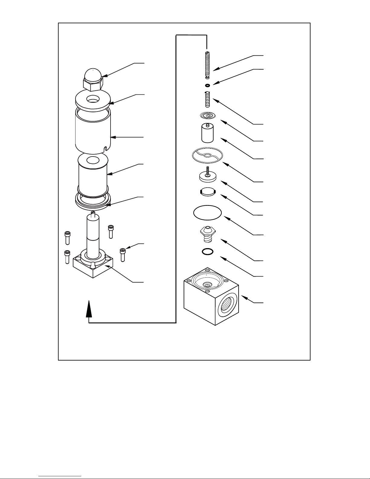
FIGURE 6-1 SOLENOID VALVE
Various corrosive gases may demand more frequent replacement of FKM
O-rings and seals inside the valve. Be sure to use an elastomer material, appropriate for your specific gas application. Contact OMEGA
®
for optional sealing
materials available.
Set the FMA 5400A/5500A into PURGE mode (see Figure 2-1), and attempt to
flush through with a clean, filtered, and neutral gas such as nitrogen. [Another
option for fully opening the valve is to remove the plastic cap on top of the valve,
and turning the set screw counterclockwise until it stops. See section 7.3 f or v alv e
adjustment, to return the valve to functional use.]
17
SPIDER SPRING
STEM
SEAT-VITON
INSERT
ORIFICE
O-RING
BLOCK
CORE
SPIRAL SPRING
COMPRESSION
SPRING
O-RING
O-RING
ADJUST. SCREW
11-20-2013
NUT
GUARD
TOP
GUARD
COIL
GUARD
BASE
VALVE
BODY
4-40
SOCKET
SCREW
Page 23

7. CALIBRATION PROCEDURES
NOTE: Removal of the factory installed calibration seals and/or any
adjustments made to the meter, as described in this section, will void
any calibration warranty applicable.
7.1 Flow Calibration
OMEGA
®
Engineering Flow Calibration Laboratory offers professional calibration
support for Mass Flow Meter and Controllers, using precision calibrators under
strictly controlled conditions. NIST traceable calibrations are available.
Calibrations can also be performed by customers using available certified standards.
Factory calibrations are perf ormed using state of the art NIST traceable precision
volumetric calibrators.
Calibrations are performed using dry nitrogen gas. Calibration can then be corrected to the appropriate gas desired based on relative correction [K] factors
shown in the gas factor table - see Appendix 2. A reference gas, other than nitrogen, may be used to approximate the flow characteristics of certain gases closer.
This practice is recommended when a reference gas is f ound with thermodynamic
properties similar to the actual gas under consideration. The appropriate relative
correction factor should be recalculated - see section (9).
It is standard practice to calibrate Mass Flow Controllers with dry nitrogen gas. It
is best to calibrate the FMA Series Max. Flow 100 L/min transducers to actual
operating conditions. Specific gas calibrations of non-toxic and non-corrosive
gases are available at specific conditions. Please contact OMEGA7 for a price
quotation.
It is recommended that a flow calibrator of at least four times better collective
accuracy than that of the Mass Flow Controller to be calibrated be used.
Equipment required for calibration includes a flow calibr ation standard and a certified high sensitivity multimeter (which together have a collective accuracy of
±0.25% or better), an insulated (plastic) screwdriver, a flow regulator (example:
metering needle valve) installed upstream from the Mass Flow Controller and a
pressure regulated source of dry filtered nitrogen gas (or other suitable reference
gas).
The gas and ambient temperature, as well as inlet and outlet pressure conditions
should be set up in accordance with actual operating conditions.
18
,
Page 24
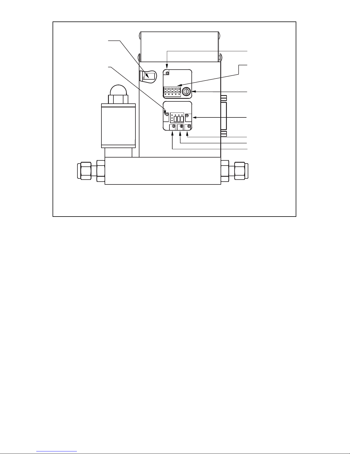
FIGURE 7-1 FMA 5400A/5500A SERIES MAX. FLOW 10, 50, 100 L/MIN CALIBRATION
POTENTIOMETER AND JUMPER LOCATIONS (BACK OF FMA 5400A/5500A )
7.2 Calibration of FMA 5400A/5500A Series Max.
Flow 10, 50, 100 L/min Mass Flow Controllers
All adjustments in this section are made from the outside of the meter, there is no
need to disassemble any part of the instrument.
FMA 5400A/5500A Mass Flow Controllers may be field recalibrated/checked for
the same range they were originally factory calibrated for. When linearity adjustment is needed, or flow range changes are being made proceed to step 7.2.4.
Flow range changes may require a different Restrictor Flow Element (RFE).
Additionally, a different Solenoid Valve Orifice may also be required (see Table VI).
Consult OMEGA
®
for more infor mation.
7.2.1 Connections and Initial Warm Up
At the 15-pin “D” connector of the FMA 5400A/5500A transducer, connect the
multimeter to output pins [1] and [2] for 0 to 5 VDC (or pins [9] and [14] for 4 to 20
mA) - (see Figure 2-1).
When using a remote setpoint for flow control, the appropriate reference signal
should also be connected to the 15-pin “D” connector at pins [8] and [10] - (see
Figure 2-1). Power up the Mass Flow Controller for at least 30 minutes prior to
commencing the calibration procedure.
19
NR7
LOCAL SET POINT
POTENTIOMETER
R34 ZERO
POTENTIOMETER
R38 50%
R39 75%
R40 100%
R33
SPAN (10 or 25%)
R1 RESPONSE
TIME AJUSTMENT
NJ1 CONTROL
CIRCUT JUMPERS
R52 10 or 25 %
Page 25

7.2.2 ZERO Adjustment
Shut off the flow of gas into the Mass Flow Controller. To ensure that no seepage or
leak occurs into the meter, temporarily disconnect the gas source.
Using the multimeter and the insulated screwdriver, adjust the ZERO potentiometer [R34] through the access window for 0 Vdc (or 4 mA respectively) at zero
flow.
7.2.3 SPAN Adjustment
Reconnect the gas source. Adjust the control setpoint to 100% of full scale flow.
Check the flow rate indicated against the flow calibrator. If the deviation is less
than ±10% of full scale reading, correct the SPAN potentiometer [R33] setting by
using the insulated screwdriver through the access window, to eliminate any deviation. If the deviation is larger than ±10% of full scale reading, a defective condition may be present.
LIKELY REASONS FOR A MALFUNCTIONING SIGNAL MAY BE:
✓ Occluded or contaminated sensor tube.
✓ Leaking condition in the FMA 5400A/5500A transducer or the gas line and fittings.
✓ For gases other than nitrogen, recheck appropriate “K” factor from Gas Factor Table.
✓ Temperature and/or pressure correction errors.
See also section (8) TROUBLESHOOTING. If after attempting to remedy the
above conditions, a malfunction still persists, retur n the meter for factory service,
see section (1).
At this point the calibration is complete. However, it is advisable that sev er al additional points between 0 and 100%, such as 25%, 50%, and 75% flow be check ed.
If discrepancies are found, proceed to step 7.2.4 for Linear ity Adjustment.
7.2.4 Linearity Adjustment
All adjustments in this section are made from the outside of the meter, there is no
need to disassemble any part of the instrument.
7.2.4.1 Disable Solenoid Valve in FMA 5400A/5500A
Series Max. Flow 10, 50, 100 L/min
Set the valve into PURGE mode. This step essentially bypasses the flow control
properties of the transducer. The unit will now act as a Mass Flow Meter.
CAUTION: FOR FMA 5400A/5500A Ser ies Max. Flow 10, 50, 100
L/min- If the valve is left in the AUTO (control) or OPEN (PURGE)
mode for an extended per iod of time, it may become warm or even
hot to the touch. Use care in avoiding direct contact with the valve
during operation.
20
Page 26

7.2.5 Connections and Initial Warm Up
Connect the multimeter to output pins [1] and [2] for 0 to 5 VDC (or pins [9] and
[14] for 4 to 20 mA) of the 15-pin “D” connector - (see Figure 2-1).
If calibration to a new flow range or different gas is being performed, it may be
necessary to remove any jumpers at J1A, J1B, J1C and J1D before beginning linearizing procedure.
Power up the Mass Flow Controller for at least 30 minutes prior to commencing
the calibration procedure.
7.2.6 ZERO Adjustment
Shut off the flow of gas into the Mass Flow Controller. To ensure that no seepage
or leak occurs into the meter, it is good pr actice to temporarily disconnect the gas
source.
Using the multimeter and the insulated screwdriver, adjust the ZERO LCD reading and 0 Vdc (or 4 mA respectively) analog output reading at zero flow by adjusting the zero potentiometer [R34] through the access window.
7.2.7 25% Flow Adjustment
Reconnect the gas source. Using the flow regulator, adjust the flow rate to 25% of
full scale flow. Check the flow rate indicated against a flow calibrator. Adjust the
setting for potentiometer [R33] by using the insulated screwdriver through the
access window, until the output of the flow meter reads 1.25VDC ±63mV (or 8mA
±0.25mA).
Using the flow regulator, adjust the flow rate until the output of the flow meter
reads 0.5 Vdc (or 5.6mA). Check the flow rate against the flow calibrator. If the
flow rate indicated by the calibrator is within 10% ± 1.0% of F.S. then skip paragraphs 7.2.8, 7.2.9 and proceed directly to paragraph 7.2.10, if not, perform 10%
flow adjustment according to paragraph 7.2.8.
21
CAUTION: The minimum voltage on 0-5 Vdc output can be in the
range of 7 to 25 mV. Tr ying to reduce voltage below this level may
increase negative zero shift. This shift may be invisible on devices without LCD display. Stop R34 zero potentiometer adjustment if voltage on
0-5 Vdc output is in the range from 7 to 25 mV and does not decrease
any lower.
Page 27

7.2.8 10% Flow Adjustment
Using the flow regulator, adjust the flow rate to 10% of full scale flow according to
the calibrator. Check the flow rate indicated against the flow calibrator. Adjust the
setting for potentiometer [R33] by using the insulated screwdriver through the
access window, until the output of the flow meter reads 0.5 Vdc ±63mV (or 5.6mA
±0.25mA).
7.2.9 25% Flow Adjustment (using R52 potentiometer)
Using the flow regulator, adjust the flow rate to 25% of full scale flow according to
the calibrator. Check the flow rate indicated against the flow calibrator. The output
of the flow meter should read 1.25 Vdc ±63mV (or 8.0mA ±0.25mA). If the reading
is outside of that range, place the jumper at [J1.A] as appropriate to increase or
decrease the signal. Adjust the setting for potentiometer [R52] by using the insulated screwdriver through the access window, until reading is within specification.
7.2.10 50% Flow Adjustment
Using the flow regulator , increase the flo w rate to 50% of full scale flo w. Chec k the
flow rate indicated against the flow calibrator. The output of the flow meter should
read 2.50 Vdc ±63mV (or 12mA ±0.25mA). If the reading is outside of that range,
place the jumper at [J1B] as appropriate to increase or decrease the signal. Adjust
the setting for potentiometer [R38] by using the insulated screwdriver through the
access window, until reading is within specification.
7.2.11 75% Flow Adjustment
Using the flow regulator , increase the flo w rate to 75% of full scale flo w. Chec k the
flow rate indicated against the flow calibrator. The output of the flow meter should
read 3.75 Vdc ±63mV (or 16mA ±0.25mA). If the reading is outside of that range,
place the jumper at [J1C] as appropriate to increase or decrease the signal.
Adjust the setting for potentiometer [R39] by using the insulated screwdriver
through the access window, until reading is within specification.
7.2.12 100% Flow Adjustment
Using the flow regulator, increase the flow rate to 100% of full scale flow. Check
the flow rate indicated against the flow calibrator. The output of the flow meter
22
LINEARIZER
FUNCTION
J1A (10
or 25%)
J1B
(50%)
J1C
(75%)
J1D
(100%)
Decrease 1 - 2 4 - 5 7 - 8 10 - 11
Increase
2 - 3 5 - 6 8 - 9 11 - 12
3
6912
2
1
4
5
8
71110
ABCD
FIGURE 7-2 FMA 5400A/5500A SERIES MAX. FLOW 10, 50, 100 L/min
CALIBRATION POTENTIOMETER AND JUMPERS
Page 28

should read 5.00VDC ±63mV (or 20mA ±0.25mA). If the reading is outside of that
range, place the jumper at [J1C] as appropriate to increase or decrease the signal. Adjust the setting for potentiometer [R40] by using the insulated screwdriver
through the access window, until reading is within specification.
Repeat steps 7.2.7 to 7.2.10 at least once more.
7.2.13 VALVE ADJUSTMENT
7.2.13.1 Valve Adjustment for
FMA Series Max. Flow 10, 50 and 100 L/min
Discontinue the PURGE mode (set valve for the closed position). Apply an inlet
pressure of 5 psig, and atmospheric pressure at the outlet. If a small flow occurs,
turn the set screw on top of the solenoid valve cloc kwise until the flo w through the
FMA 5400A/5500A just stops.
7.2.14 Close Loop Full Scale Flow Adjustment
Fully open the flow regulator upstream of the FMA 5400A/5500A. Increase the
inlet pressure to 20 psig (25 psig for FMA Series Max. Flow 100 L/min). Apply a
+5.00 VDC (100% full scale flow) setpoint reference. Using the calibrator check
the flow rate. If necessary, adjust R33 to match the desired full scale flow rate. [In
control mode, turning R33 clockwise will decrease the flow. Conversely, tur ning
R33 counterclockwise will increase the flow through the FMA 5400A/5500A.]
7.2.15 10% Close Loop Flow Adjustment
(using R33 potentiometer)
If the J1A jumper is not installed in upper or lower position (paragraphs
7.2.8 and 7.2.9 were skipped) then skip this paragraph and paragraph 7.2.16.
Proceed directly to paragraph 7.2.17. Change the setpoint to 0.5 Vdc to control
at 10% of full scale flow. Check the flow rate indicated against the flow calibrator.
If the flow is not within ±0.75% of full scale, re-adjust the setting for potentiometer [R33], until the flow output is correct.
7.2.16 25% Close Loop Flow Adjustment
(using R52 potentiometer)
Change the setpoint to 1.25 Vdc to control at 25% of full scale flo w. Chec k the flow
rate indicated against the flow calibrator. If the flow is not within ±0.75% of full
scale, re-adjust the setting for potentiometer [R52], until the flow output is correct.
7.2.17 Close Loop 25% Flow Adjustment
(using R33 potentiometer)
Change the setpoint to 1.25 VDC to control at 25% of full scale flow. Check the
flow rate indicated against the flow calibrator. If the flow is not within ±0.75% of
full scale, re-adjust the setting for potentiometer [R33], until the flo w output is correct.
23
Page 29
7.2.18 Close Loop 50% Flow Adjustment
Change the setpoint to 2.50 VDC to control at 50% of full scale flow. Check the
flow rate indicated against the flow calibrator. If the flow is not within ±0.75% of
full scale, re-adjust the setting for potentiometer [R38], until the flo w output is correct.
7.2.19 Close Loop 75% Flow Adjustment
Change the setpoint to 3.75 VDC to control at 75% of full scale flow. Check the
flow rate indicated against the flow calibrator. If the flow is not within ±0.75% of
full scale, re-adjust the setting for potentiometer [R39], until the flo w output is correct.
7.2.20 Close Loop 100% Flow Adjustment
Change the setpoint to 5.00 VDC to control at 100% of full scale flow. Check the
flow rate indicated against the flow calibrator. If the flow rate is not within ±0.75%
of full scale, re-adjust the setting for potentiometer [R40], until the flow output is
correct.
Repeat steps 7.2.15 to 7.2.20 at least once more.
24
ORIFICE PART NUMBER FLOW RATE [N2]
OR.020 10 to 1000 sccm
OR.040 1 to 5 slpm
OR.055 5 to 10 slpm
OR.063 10 to 15 slpm
OR.094 20 to 50 slpm
OR.125 50 to 100 slpm
TABLE II FMA 5400A/5500A SOLENOID VALVE ORIFICE SELECTION TABLE
7.3 Calibration of FMA 5400A/5500A Series Max.
Flow 200, 500 and 1000 L/min
Mass Flow Controllers
All adjustments in this section are made from the outside of the meter, there is no
need to disassemble any part of the instrument. FMA 5400A/5500A Mass Flow
Controllers may be field recalibrated/checked for the same range they were originally factory calibrated for. When linearity adjustment is needed, or flow range
changes are being made proceed to step 7.2.4. Flow range changes may require
a different Restrictor Flow Element (RFE). Additionally, a different Solenoid Valve
Orifice may also be required (see Table VI). Consult Omega
®
for more inf ormation.
Page 30
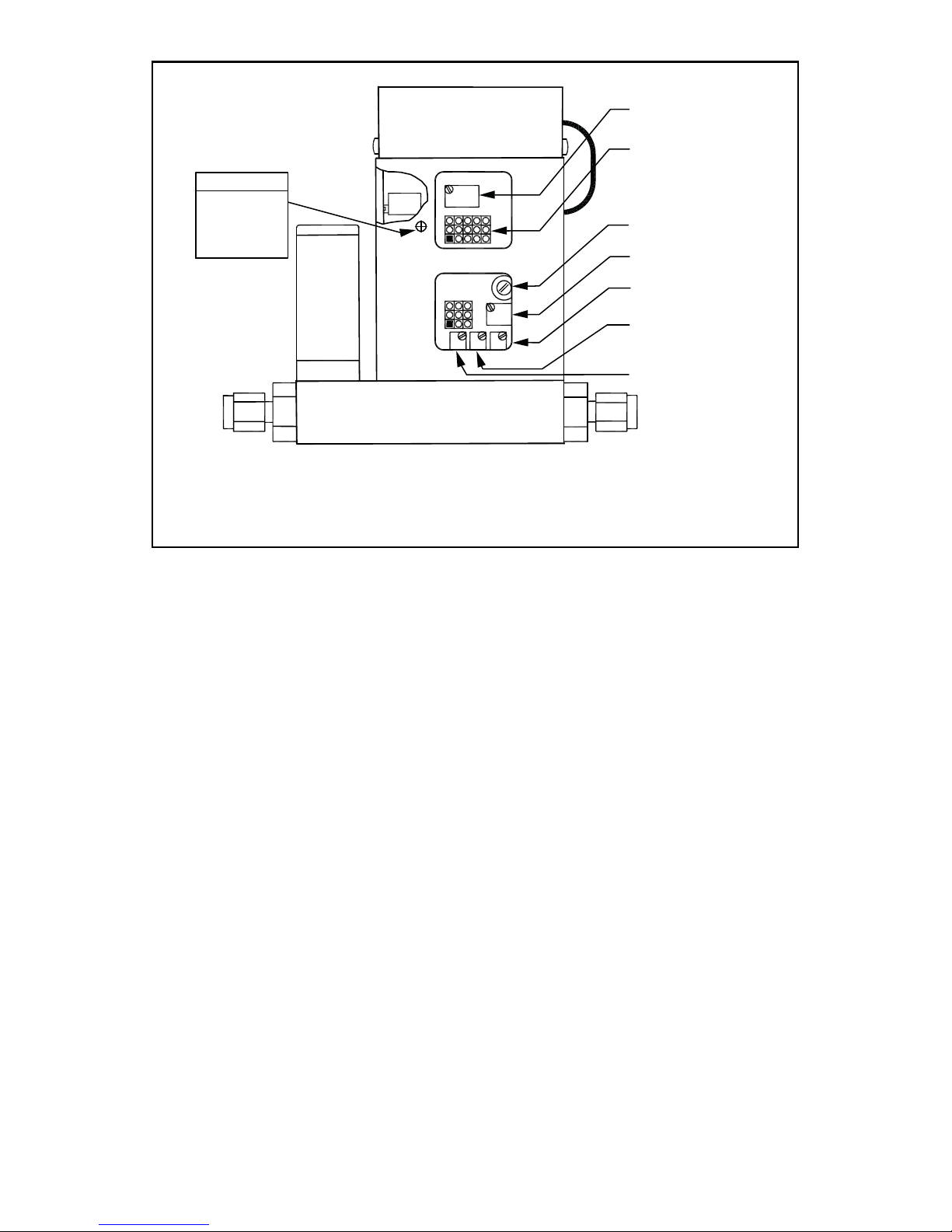
25
R34
ZERO
POTENTIOMETER
NJ1 CONTROL
CIRCUT JUMPERS
R1 RESPONSE
TIME ADJUSTMENT
R33
SPAN (25%)
R40 100%
R39 75%
R38 50%
LOCAL
SETPOINT
POTENTIOMETER
NR7
GFC 57 / 67 / 77
FIGURE 7-3 FMA 5400A/5500A SERIES MAX. FLOW 200, 500 AND 1000 L/MIN
CALIBRATION POTENTIOMETER AND JUMPER LOCATIONS (BACK OF FMA 5400A/5500A)
7.3.1 Connections and Initial Warm Up
At the 15-pin “D” connector of the FMA 5400A/5500A transducer, connect the
multimeter to output pins [1] and [2] for 0 to 5 Vdc (or pins [9] and [14] for 4 to 20
mA) - (see Figure 2-1). When using a remote setpoint for flow control, the appropriate reference signal should also be connected to the 15-pin “D” connector at
pins [8] and [10] - (see Figure 2-1). Power up the Mass Flow Controller for at least
30 minutes prior to commencing the calibration procedure.
7.3.2 ZERO Adjustment
Shut off the flow of gas into the Mass Flow Controller. To ensure that no seepage
or leak occurs into the meter, temporar ily disconnect the gas source. Using the
multimeter and the insulated screwdriver, adjust the ZERO potentiometer [R34]
through the access window for 0 Vdc (or 4 mA respectively) at zero flow.
7.3.3 SPAN Adjustment
Reconnect the gas source. Adjust the control setpoint to 100% of full scale flow.
Check the flow rate indicated against the flow calibrator. If the deviation is less
than ±10% of full scale reading, correct the SPAN potentiometer [R33] setting by
using the insulated screwdriver through the access window, to eliminate any deviation. If the deviation is larger than ±10% of full scale reading, a defective condition may be present.
Page 31

26
See also section (8) TROUBLESHOOTING. If after attempting to remedy the
above conditions, a malfunction still persists, retur n the meter for factory service,
see section (1). At this point the calibration is complete. However, it is advisable
that several additional points between 0 and 100%, such as 25%, 50%, and 75%
flow be checked. If discrepancies are found, proceed to step 7.3.4 for Linearity
Adjustment.
LIKELY REASONS FOR A MALFUNCTIONING SIGNAL MAY BE:
✓ Occluded or contaminated sensor tube.
✓ Leaking condition in the FMA 5400A/5500A transducer or the gas line and fittings.
✓ For gases other than nitrogen, recheck appropriate “K” factor from Gas Factor Table.
✓ Temperature and/or pressure correction errors.
7.3.4 Linearity Adjustment
All adjustments in this section are made from the outside of the meter, there is
no need to disassemble any part of the instrument.
7.3.4.1 Open Motorized Valve in FMA 5400A/5500A
Series Max. Flow 200, 500 and 1000 L/min
Set the valve to PURGE mode by connecting pin [4] to pin [3], at the 15 pin
D-connector.
7.3.5 Connections and Initial Warm Up
Connect the multimeter to output pins [1] and [2] for 0 to 5 Vdc (or pins [9] and
[14] for 4 to 20 mA) of the 15-pin “D” connector - (see Figure 2-1). If calibration to
a new flow range or different gas is being performed, it may be necessary to
remove any jumpers at J1A, J1B, and J1C before beginning linearizing procedure.
Power up the Mass Flow Controller for at least 30 minutes prior to commencing
the calibration procedure.
7.3.6 ZERO Adjustment
Shut off the flow of gas into the Mass Flow Controller. To ensure that no seepage
or leak occurs into the meter, it is good pr actice to temporarily disconnect the gas
source. Using the multimeter and the insulated screwdriver, adjust the ZERO
potentiometer [R34] through the access window for 0 Vdc (or 4 mA respectively)
at zero flow.
7.3.7 25% Flow Adjustment
Reconnect the gas source. Using the flow regulator, adjust the flow rate to 25%
of full scale flow. Check the flow rate indicated against the flow calibrator. Adjust
the setting for potentiometer [R33] by using the insulated screwdriver through
the access window, until the output of the flow meter reads 1.25 Vdc ±63mV (or
8mA ±0.25mA).
Page 32

27
FIGURE 7-4 FMA 5400A/5500A SERIES MAX. FLOW 200, 500 AND 1000
L/MIN CALIBRATION POTENTIOMETER AND JUMPERS
LINEARIZER
FUNCTION
J1A (50%) J1B (75%) J1C (100%)
Decrease 1 - 2 4 - 5 7 - 8
Increase
2 - 3 5 - 6 8 - 9
7.3.8 50% Flow Adjustment
Using the flow regulator , increase the flow r ate to 50% of full scale flow. Chec k the
flow rate indicated against the flow calibrator. The output of the flow meter should
read 2.50 Vdc ±63mV (or 12mA ±0.25mA). If the reading is outside of that range,
place the jumper at [J1A] as appropriate to increase or decrease the signal.
Adjust the setting for potentiometer [R38] by using the insulated screwdriver
through the access window, until reading is within specification.
7.3.9 75% Flow Adjustment
Using the flow regulator , increase the flow r ate to 75% of full scale flow. Chec k the
flow rate indicated against the flow calibrator. The output of the flow meter should
read 3.75 Vdc ±63mV (or 16mA ±0.25mA). If the reading is outside of that range,
place the jumper at [J1B] as appropriate to increase or decrease the signal.
Adjust the setting for potentiometer [R39] by using the insulated screwdriver
through the access window, until reading is within specification.
7.3.10 100% Flow Adjustment
Using the flow regulator, increase the flow rate to 100% of full scale flow. Check
the flow rate indicated against the flow calibrator. The output of the flow meter
should read 5.00 Vdc ±63mV (or 20mA ±0.25mA). If the reading is outside of that
range, place the jumper at [J1C] as appropriate to increase or decrease the signal. Adjust the setting for potentiometer [R40] by using the insulated screwdriver
through the access window, until reading is within specification. Repeat steps
7.2.7 to 7.2.10 at least once more.
7.3.11. VALVE ADJUSTMENT
7.3.11.1 Valve Adjustment for FMA 5400A/5500A
Series Max. Flow 200, 500 and 1000 L/min
Discontinue the PURGE mode (set valve for the Auto position). DO NOT adjust
the motorized valve for FMA 5400A/5500A Series Max. Flow 200, 500 and 1000
L/min. The motorized valve for these models has been pre-adjusted at the factory.
Page 33

28
7.3.12 Full Scale Flow Adjustment
Fully open the flow regulator upstream of the FMA 5400A/5500A. Increase the inlet
pressure to 20 psig. Apply a +5.00 Vdc (100% full scale flow) setpoint reference.
Using the calibrator check the flow rate. If necessary, adjust R33 to match the
desired full scale flow rate. [In control mode, turning R33 clockwise will decrease
the flow. Conversely, turning R33 counterclockwise will increase the flow through
the FMA 5400A/5500A.]
7.3.13 25% Flow Adjustment
Change the setpoint to 1.25 Vdc to control at 25% of full scale flow. Check the
flow rate indicated against the flow calibrator. If the flow is not within ±0.75%
of full scale, re-adjust the setting for potentiometer [R33], until the flo w output is correct.
7.3.14 50% Flow Adjustment
Change the setpoint to 2.50 Vdc to control at 50% of full scale flow. Check the
flow rate indicated against the flow calibrator. If the flow is not within ±0.75%
of full scale, re-adjust the setting for potentiometer [R38], until the flo w output is correct.
7.3.15 75% Flow Adjustment
Change the setpoint to 3.75 Vdc to control at 75% of full scale flow. Check the
flow rate indicated against the flow calibrator. If the flow is not within ±0.75%
of full scale, re-adjust the setting for potentiometer [R39], until the flo w output is correct.
7.3.16 100% Flow Adjustment
Change the setpoint to 5.00 Vdc to control at 100% of full scale flow. Check the
flow rate indicated against the flow calibrator. If the flow rate is not within ±0.75%
of full scale, re-adjust the setting for potentiometer [R40], until the flo w output is correct.
Repeat steps 7.3.13 to 7.3.16 at least once more.
7.4 LCD Display Scaling
It may be desirable to re-scale the output reading on the LCD readout supplied
with certain model FMA 5400A/5500A transducers. Re-calibration for a new flow
range or different engineering units are two examples of when this may be necessary.
7.4.1 Access LCD Display Circuit
Carefully remove the LCD from the FMA 5400A/5500A or panel mounted surf ace .
Remove the aluminum housing on the side of the connection cab le. Slide the LCD
assembly out of the aluminum housing.
Page 34
29
7.4.2 Adjust Scaling
Using a digital multimeter connected to either the 0 to 5 VDC or 4 to 20 mA signal at the 15-pin “D” connector, set the flow rate on the FMA 5400A/5500A to full
scale flow (5 VDC or 20mA). Maintain full scale flow, and adjust the potentiometer [R3] on the LCD printed circuit board to desired full scale flow reading.
7.4.3 Change Decimal Point
To change the decimal place on the LCD display readout, simply move the jumper
to the appropriate location on the 8-pin header block. The numbers are printed to
the side of the connections. Do not attempt to place more than one jumper for
decimal setting.
8. TROUBLESHOOTING
8.1 Common Conditions
Your Mass Flow Controller/Controller was thoroughly checked at numerous quality control points during and after manufacturing and assembly operations. It was
calibrated in accordance to your desired flow and pressure conditions for a given
gas or a mixture of gases.
It was carefully packed to prevent damage during shipment. Should you feel that
the instrument is not functioning properly please check for the following common
conditions first:
✓ Are all cables connected correctly?
✓ Are there any leaks in the installation?
✓ Is the power supply correctly selected according to requirements?
When several meters are used a power supply with appropriate current
rating should be selected.
✓ Were the connector pinouts matched properly? When interchanging with
other manufacturers' equipment, cables and connectors must be carefully
wired for correct pin configurations.
✓ Is the pressure differential across the instrument sufficient?
JUMPER POSITION
MAXIMUM SCALABLE DISPLAY READING
“0” 1999
“3”
199.9
“2”
19.99
“1” 1.999
Page 35
30
8.2 General Troubleshooting Guide
INDICATION LIKELY REASON REMEDY
lack of reading
or output
power supply off check connection of power supply
fuse blown disconnect transducer from
power supply; remove the
shorting condition or check
polarities; fuse resets
automatically
filter screen
obstructed at inlet
flush clean or disassemble to
remove impediments or replace
occluded sensor tube flush clean or disassemble to
remove impediments or return to
factory for replacement
pc board defect return to factory for replacement
FMA 5400A/5500A Series Max
Flow 10, 50, 100 L/min
valve adjustment wrong
re-adjust valve (section 8.3.3)
flow reading
does not
coincide with
the setpoint
inadequate gas pressure apply appropriate gas pressure
filter screen obstructed
at inlet
flush clean or disassemble to
remove impediments or replace
ground loop signal and power supply
commons are different
no response
to setpoint
inadequate gas pressure apply appropriate gas pressure
cable or connector malfunction check cables and all connections
or replace
setpoint is too low
(<2% of full scale)
re adjust setpoint or disable 2%
cutoff feature (section 2.2)
FMA 5400A/5500A Series Max
Flow 10, 50, 100 L/min valve
adjustment wrong
re-adjust valve
(section 8.3.3 below)
unstable or no
zero reading
gas leak locate and correct
pc board defective return to factory for replacement
FMA 5400A/5500A Series Max
Flow 10, 50, 100 L/min
valve adjustment wrong
re-adjust valve (see section 8.3.2
below)
Page 36
31
INDICATION LIKELY REASON REMEDY
full scale output
at “no flow”
condition or
with valve
closed
defective sensor return to factory for replacement
gas leak locate and repair
FMA 5400A/5500A Series Max
valve Flow 10, 50, 100 L/min
adjustment wrong
re-adjust valve (section
8.3.1 below)
calibration off
gas metered is not the same as
what meter was calibrated for
use matched calibration
composition of gas changed see K factor tables in APPENDIX 2
gas leak locate and correct
pc board defective return to factory for replacement
RFE dirty
flush clean or disassemble to
remove impediments
occluded sensor tube
flush clean or disassemble to
remove impediments or return to
factory for replacement
filter screen obstructed
at inlet
flush clean or disassemble to
remove impediments or replace
transducer is not
mounted properly
check for any tilt or change in the
mounting of the transducer;
generally, units are calibrated for
horizontal installation (relative to
the sensor tube)
FMA
5400A/5500A
valve does
not work
in open position
FMA 5400A/5500A Series Max
Flow 10, 50, 100 L/min
incorrect valve adjustment
re-adjust valve (section 8.3.3)
pc board defect return to factory for replacement
cable or connectors
malfunction
check cable and connectors
or replace
differential pressure too high
decrease pressure to correct level
insufficient inlet pressure adjust appropriately
Page 37
32
8.3 FMA 5400A/5500A Series Max. Flow 10, 50
and 100 L/min Valve Related Troubleshooting
8.3.1 INDICATION: LIKELY REASON: REMEDY:
With “no flow
conditions” (gas pipes
are not connected to the
FMA 5400A/5500A) and
valve closed (pins 3 and
12 are connected
together) LCD reading
is zero, but when 20
PSIG inlet pressure is
applied the LCD reads
more than 0.5% of full
scale.
Valve is out of
adjustment and
leaking.
1. Adjust control set point to zero. Set
Valve mode to “CLOSE” position
(connect pins 3 and 12 on the 15 pins
D-connector together). This step is very
important!
2. Apply 20 PSIG inlet pressure.
3. See operating manual page 17 (Figure
6-1). Unscrew hex nut cover on the top
of the solenoid valve.
4. Using a screwdriver readjust adjustment
screw on the top of the valve to CW
(clock wise) direction until zero reading
on the display. Be very careful during
adjustment: make only 15 degree turn
each time and wait one minute due
to the sensor’s response time. If reading
is still high make another 15 degree turn.
Do not over adjust valve. If you made
more than 5 complete (360 degree)
turns and leakage still exists stop
adjustment. In this case unit has to be
returned to the factory for servicing.
5. This is not a shut off valve. It is normal
to observe up to 0.5 % of F.S. leakage.
6. Adjust hex nut cover on the top of the
solenoid valve.
7. Disable Valve “Close” mode,
apply 100% control set point and check
if reading can reach 100% reading.
INDICATION LIKELY REASON REMEDY
FMA
5400A/5500A
valve not
not work in
closed position
FMA 5400A/5500A Series Max
Flow 10, 50, 100 L/min
incorrect valve adjustment
re-adjust valve (section 8.3.1)
pc board defect
return to factory for replacement
cable or connectors check cable and connectors
or replace
orifice obstructed disassemble to remove
impediments or return to factory
Page 38

33
8.3.2 INDICATION: LIKELY REASON: REMEDY:
Differential pressure
across the
FMA 5400A/5500A
controller is within
specification but LCD
reading and actual flow
are not stable (oscillate
1-4 times per second).
Valve
compression
spring is over
adjusted and PID
control cannot
handle stable
flow.
1. Make sure differential pressure across
the FMA 5400A/5500A is within
specification.
2. Install control set point to 100% F.S.
This should remedy the oscillation
conditions.
3. See operating manual page 17
(Figure 6-1). Unscrew hex nut cover on
the top of the solenoid valve.
4. Using screwdriver readjust adjustment
screw on the top of the valve to CCW
(counter clock wise) direction until
reading on the display will be stable. Be
very careful during adjustment: make
only 15 degree turn each time and
wait about 15 seconds due to sensor’s
response time. If reading oscillates
make another 15 degree turn. Do not
over adjust valve. If you noticed that
flow rate is constant and more than
105% of full scale, it means you over
adjusted valve and it has leakage. In this
case make adjustment to CW (clock
wise) in order to fix this problem until
reading will go back to 100% full scale.
5. Adjust zero set point (or valve close
command), wait about 3 minutes and
check if valve is able to close.
6. This is not a shut off valve. It is normal
to observe up to 0.5 % of F.S. leakage.
7. Install hex nut cover on the top of the
solenoid valve.
Page 39

34
8.3.3 INDICATION: LIKELY REASON: REMEDY:
Differential pressure
across the
FMA 5400A/5500A
controller is within
specification but flow
rate reading is more
than 1% F.S. below set
point value when 100%
set point is applied.
Valve
compression
spring is over
adjusted and
controller does
not have enough
power to open
valve and reach
100% F.S. flow.
1. Make sure differential pressure across
the FMA 5400A/5500A is within
specification.
2. Adjust control set point to 100% F.S.
This should remedy initial fault
conditions (flow reading is less than set
point value and difference is more than
1% F.S.).
3. See operating manual page 17 (Figure
6-1). Unscrew hex nut cover on the top
of the solenoid valve.
4. Using screwdriver readjust adjustment
screw on the top of the valve to CCW
(counter clock wise) direction until
reading on the display will be equal to
the set point value. Be very careful
during adjustment: make only 15
degree turn each time and wait about
15 seconds due to sensors responds time.
If reading still below 100% make
another 15 degree turn. Do not over
adjust valve. If you noticed that flow
rate is constant and more than 105%
of full scale, it means you over adjusted
valve and it has leakage. In this case
make adjustment to CW (clock wise) in
order to fix this problem until reading
will go back to 100% full scale.
5. Install zero set point (or valve close
command), wait about 3 minutes and
check if valve is able to close.
6. This is not a shut off valve. It is normal
to observe up to 0.5 % of F.S. leakage.
7. Install hex nut cover on the top of the
solenoid valve.
Page 40

35
Q
O2
= Q
a
= Q
r
X K = 1000 X 0.9926 = 992.6 sccm
where K = relative K factor to reference gas (oxygen to nitrogen)
1
d X C
p
where d = gas density (gram/liter)
C
p
= coefficient of specific heat (cal/gram)
Q
a
K
a
Q
r
K
r
where Qa= mass flow rate of an actual gas (sccm)
Q
r
= mass flow rate of a reference gas (sccm)
K
a
= K factor of an actual gas
K
r
= K factor of a reference gas
=
9. CALIBRATION CONVERSIONS FROM
REFERENCE GASES
The calibration conversion incorporates the K factor. The K factor is derived from
gas density and coefficient of specific heat. For diatomic gases:
=
K
=
K
gas
Note: in the abo v e relationship that d and Cp are usually chosen at the same conditions (temperature, pressure).
If the flow range of a Mass Flow Controller remains unchanged, a relative K factor is used to relate the calibration of the actual gas to the reference gas.
For example, if we want to know the flow rate of oxygen and wish to calibrate
with nitrogen at 1000 SCCM, the flow rate of oxygen is:
NOTE: One common reason for propor tional solenoid valve to be out of
adjustment: keeping control set point even very small (2% for example)
while disconnecting inlet pressure. In this case the valve becomes
overheated within 15 minutes and mechanical char acteristics of the seat
insert and compression spring are compromised. Avoid this mode of
operation in the future.
For best results it is recommended that instruments are returned to the factory for
servicing. See section 1.3 for retur n procedures.
8.4 Technical Assistance
OMEGA
®
Engineering will provide technical assistance over the phone to quali-
fied repair personnel. Please call our Flow Department at 800-872-9436 Ext.
2298.
,
Page 41
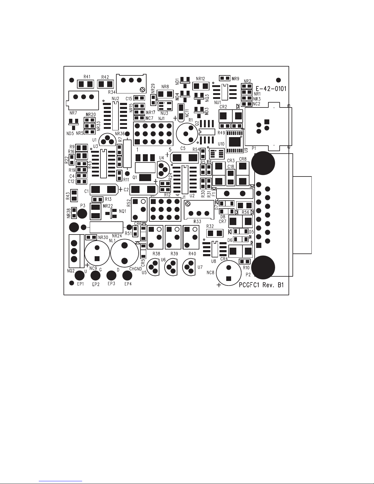
36
APPENDIX 1
COMPONENTS DIAGRAM
FMA 5400A/5500A SERIES MAX. FLOW 10, 50 AND 100 L/MIN PC BOARD
(TOP SIDE)
Page 42
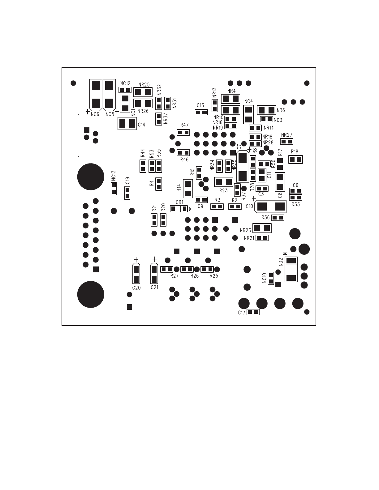
37
COMPONENTS DIAGRAM
FMA 5400A/5500A SERIES MAX. FLOW 10, 50 AND 100 L/MIN PC BOARD
(BOTTOM SIDE)
Page 43
38
APPENDIX 2
GAS FACTOR TABLE (“K” FACTORS)
CAUTION: K-Factors at best are only an approximation. K factors should not
be used in applications that require accuracy better than +/- 5 to 10%.
ACTUAL GAS
K FACTOR
Relative to N
2
Cp
[Cal/g]
Density
[g/I]
Acetylene C2H
2
.5829 .4036 1.162
Air 1.0000 .240 1.293
Allene (Propadiene) C3H
4
.4346 .352 1.787
Ammonia NH
3
.7310 .492 .760
*Argon Ar
*Argon AR-1 (>10 L/min)
1.4573
1.205
.1244
.1244
1.782
1.782
Arsine AsH
3
.6735 .1167 3.478
Boron Trichloride BCl
3
.4089 .1279 5.227
Boron Trifluoride BF
3
.5082 .1778 3.025
Bromine Br
2
.8083 .0539 7.130
Boron Tribromide Br
3
.38 .0647 11.18
Bromine PentaTrifluoride BrF
5
.26 .1369 7.803
Bromine Trifluoride BrF
3
.3855 .1161 6.108
Bromotrifluoromethane (Freon-13 B1) CBrF
3
.3697 .1113 6.644
1,3-Butadiene C4H
6
.3224 .3514 2.413
Butane C4H
10
.2631 .4007 2.593
1-Butene C4H
8
.2994 .3648 2.503
2-Butene C4H8 CIS
.324 .336 2.503
2-Butene C4H8TRANS
.291 .374 2.503
*Carbon Dioxide CO
2
*Carbon Dioxide CO2-1 (>10 L/min)
.7382
.658
.2016
.2016
1.964
1.964
Carbon Disulfide CS
2
.6026 .1428 3.397
Carbon Monoxide C0
1.00 .2488 1.250
Carbon Tetrachloride CCl
4
.31 .1655 6.860
Carbon Tetrafluoride (Freon-14)CF
4
.42 .1654 3.926
Carbonyl Fluoride COF
2
.5428 .1710 2.945
Carbonyl Sulfide COS
.6606 .1651 2.680
Chlorine Cl
2
.86 .114 3.163
Chlorine Trifluoride ClF
3
.4016 .1650 4.125
Chlorodifluoromethane (Freon-22)CHClF
2
.4589 .1544 3.858
Chloroform CHCl
3
.3912 .1309 5.326
Chloropentafluoroethane(Freon-115)C2ClF
5
.2418 .164 6.892
Chlorotrifluromethane (Freon-13) CClF
3
.3834 .153 4.660
Cyanogen C2N
2
.61 .2613 2.322
CyanogenChloride CICN
.6130 .1739 2.742
Cyclopropane C3H
5
.4584 .3177 1.877
* Flow rates indicated ( ) is the maximum flow range of the Mass Flow meter being used.
Page 44
39
* Flow rates indicated ( ) is the maximum flow range of the Mass Flow meter being used.
ACTUAL GAS
K FACTOR
Relative to N
2
Cp
[Cal/g]
Density
[g/I]
Deuterium D
2
1.00 1.722 1.799
Diborane B2H
6
.4357 .508 1.235
Dibromodifluoromethane CBr2F
2
.1947 .15 9.362
Dichlorodifluoromethane (Freon-12) CCl2F
2
.3538 .1432 5.395
Dichlofluoromethane (Freon-21) CHCl2F
.4252 .140 4.592
Dichloromethylsilane (CH3)2SiCl
2
.2522 .1882 5.758
Dichlorosilane SiH2Cl
2
.4044 .150 4.506
Dichlorotetrafluoroethane (Freon-114) C2Cl2F
4
.2235 .1604 7.626
1,1-Difluoroethylene (Freon-1132A) C2H2F
2
.4271 .224 2.857
Dimethylamine (CH3)2NH
.3714 .366 2.011
Dimethyl Ether (CH3)2O
.3896 .3414 2.055
2,2-Dimethylpropane C3H
12
.2170 .3914 3.219
Ethane C2H
6
.50 .420 1.342
Ethanol C2H6O
.3918 .3395 2.055
Ethyl Acetylene C4H
6
.3225 .3513 2.413
Ethyl Chloride C2H5Cl
.3891 .244 2.879
Ethylene C2H
4
.60 .365 1.251
Ethylene Oxide C2H4O
.5191 .268 1.965
Fluorine F
2
.9784 .1873 1.695
Fluoroform (Freon-23) CHF
3
.4967 .176 3.127
Freon-11 CCl3F
.3287 .1357 6.129
Freon-12 CCl2F
2
.3538 .1432 5.395
Freon-13 CClF
3
.3834 .153 4.660
Freon-13B1 CBrF
3
.3697 .1113 6.644
Freon-14 CF
4
.4210 .1654 3.926
Freon-21 CHCl2F
.4252 .140 4.592
Freon-22 CHClF
2
.4589 .1544 3.858
Freon-113 CCl2FCClF
2
.2031 .161 8.360
Freon-114 C2Cl2F
4
.2240 .160 7.626
Freon-115 C2ClF
5
.2418 .164 6.892
Freon-C318 C4F
8
.1760 .185 8.397
Germane GeH
4
.5696 .1404 3.418
Germanium Tetrachloride GeCl
4
.2668 .1071 9.565
*Helium He
*Helium He-1 (>50 L/min)
*Helium He-2 (>10-50 L/min)
1.454
2.43
2.05
1.241
1.241
1.241
.1786
.1786
.1786
Hexafluoroethane C2F6(Freon-116)
.2421 .1834 6.157
Hexane C6H
14
.1792 .3968 3.845
*Hydrogen H2-1
*Hydrogen H
2
-2 (>10-100 L)
*Hydrogen H
2
-3 (>100 L)
1.0106
1.35
1.9
3.419
3.419
3.419
.0899
.0899
.0899
Page 45
40
* Flow rates indicated ( ) is the maximum flow range of the Mass Flow meter being used.
ACTUAL GAS
K FACTOR
Relative to N
2
Cp
[Cal/g]
Density
[g/I]
Hydrogen Bromide HBr
1.000 .0861 3.610
Hydrogen Chloride HCl
1.000 .1912 1.627
Hydrogen Cyanide HCN
.764 .3171 1.206
Hydrogen Fluoride HF
.9998 .3479 .893
Hydrogen Iodide HI
.9987 .0545 5.707
Hydrogen Selenide H2Se
.7893 .1025 3.613
Hydrogen Sulfide H2S
.80 .2397 1.520
Iodine Pentafluoride IF
5
.2492 .1108 9.90
Isobutane CH(CH3)
3
.27 .3872 3.593
Isobutylene C4H
8
.2951 .3701 2.503
Krypton Kr
1.453 .0593 3.739
*Methane CH
4
*Methane CH4-1 (>10 L/min)
.7175
.75
.5328
.5328
.7175
.7175
Methanol CH
3
.5843 .3274 1.429
Methyl Acetylene C3H
4
.4313 .3547 1.787
Methyl Bromide CH3Br
.5835 .1106 4.236
Methyl Chloride CH3Cl
.6299 .1926 2.253
Methyl Fluoride CH3F
.68 .3221 1.518
Methyl Mercaptan CH3SH
.5180 .2459 2.146
Methyl Trichlorosilane (CH3)SiCl
3
.2499 .164 6.669
Molybdenum Hexafluoride MoF
6
.2126 .1373 9.366
Monoethylamine C2H5NH
2
.3512 .387 2.011
Monomethylamine CH3NH
2
.51 .4343 1.386
Neon NE
1.46 .246 .900
Nitric Oxide NO
.990 .2328 1.339
Nitrogen N
2
1.000 .2485 1.25
Nitrogen Dioxide NO
2
.737 .1933 2.052
Nitrogen Trifluoride NF
3
.4802 .1797 3.168
Nitrosyl Chloride NOCl
.6134 .1632 2.920
Nitrous Oxide N2O
.7128 .2088 1.964
Octafluorocyclobutane (Freon-C318) C4F
8
.176 .185 8.397
Oxygen O
2
.9926 .2193 1.427
Oxygen Difluoride OF
2
.6337 .1917 2.406
Ozone
.446 .195 2.144
Pentaborane B5H
9
.2554 .38 2.816
Pentane C5H
12
.2134 .398 3.219
Perchloryl Fluoride ClO3F
.3950 .1514 4.571
Perfluoropropane C3F
8
.174 .197 8.388
Phosgene COCl
2
.4438 .1394 4.418
Phosphine PH
3
.759 .2374 1.517
Page 46
41
ACTUAL GAS
K FACTOR
Relative to N
2
Cp
[Cal/g]
Density
[g/I]
Phosphorous Oxychloride POCl
3
.36 .1324 6.843
Phosphorous Pentafluoride PH
5
.3021 .1610 5.620
Phosphorous Trichloride PCl
3
.30 .1250 6.127
Propane C3H
8
.35 .399 1.967
Propylene C3H
6
.40 .366 1.877
Silane SiH
4
.5982 .3189 1.433
Silicon Tetrachloride SiCl
4
.284 .1270 7.580
Silicon Tetrafluoride SiF
4
.3482 .1691 4.643
Sulfur Dioxide SO
2
.69 .1488 2.858
Sulfur Hexafluoride SF
6
.2635 .1592 6.516
Sulfuryl Fluoride SO2F
2
.3883 .1543 4.562
Tetrafluoroethane (Forane 134A) CF3CH2F
.5096 .127 4.224
Tetrafluorohydrazine N2F
4
.3237 .182 4.64
Trichlorofluoromethane (Freon-11) CCl3F
.3287 .1357 6.129
Trichlorosilane SiHCl
3
.3278 .1380 6.043
1,1,2-Trichloro-1,2,2 Trifluoroethane
(Freon-113) CCl
2
FCClF
2
.2031 .161 8.36
Triisobutyl Aluminum (C4H9)AL
.0608 .508 8.848
Titanium Tetrachloride TiCl
4
.2691 .120 8.465
Trichloro Ethylene C2HCl
3
.32 .163 5.95
Trimethylamine (CH3)3N
.2792 .3710 2.639
Tungsten Hexafluoride WF
6
.2541 .0810 13.28
Vinyl Bromide CH2CHBr
.4616 .1241 4.772
Vinyl Chloride CH2CHCl
.48 .12054 2.788
Xenon Xe
1.44 .0378 5.858
Page 47
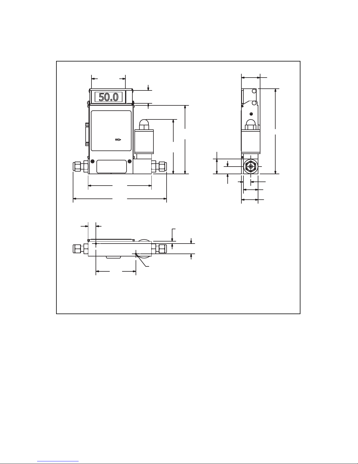
42
APPENDIX 3
DIMENSIONAL DRAWINGS
6.29
(159.8)
4.27
(108.5)
3.66
(93.0)
4.61
(117.1)
5.72 (145.3)
1.00 (25.4)
1.13 (28.6)
0.50 (12.7)
1.00
(25.4)
0.50
(12.7)
0.53
(13.5)
2.69
(68.3)
0.69 (17.5)
0.16 (4.0)
6-32 UNC - 2B 0.13
0.95 (24.1)
2.38 (60.4)
1.25 (31.8)
SERIES MAX. FLOW 10 L/min MASS FLOW CONTROLLER
NOTE: OMEGA
®
reserves the right to change designs and dimensions at its sole discretion at any time
without notice. For cer tified dimensions please contact OMEGA
®
.
Page 48
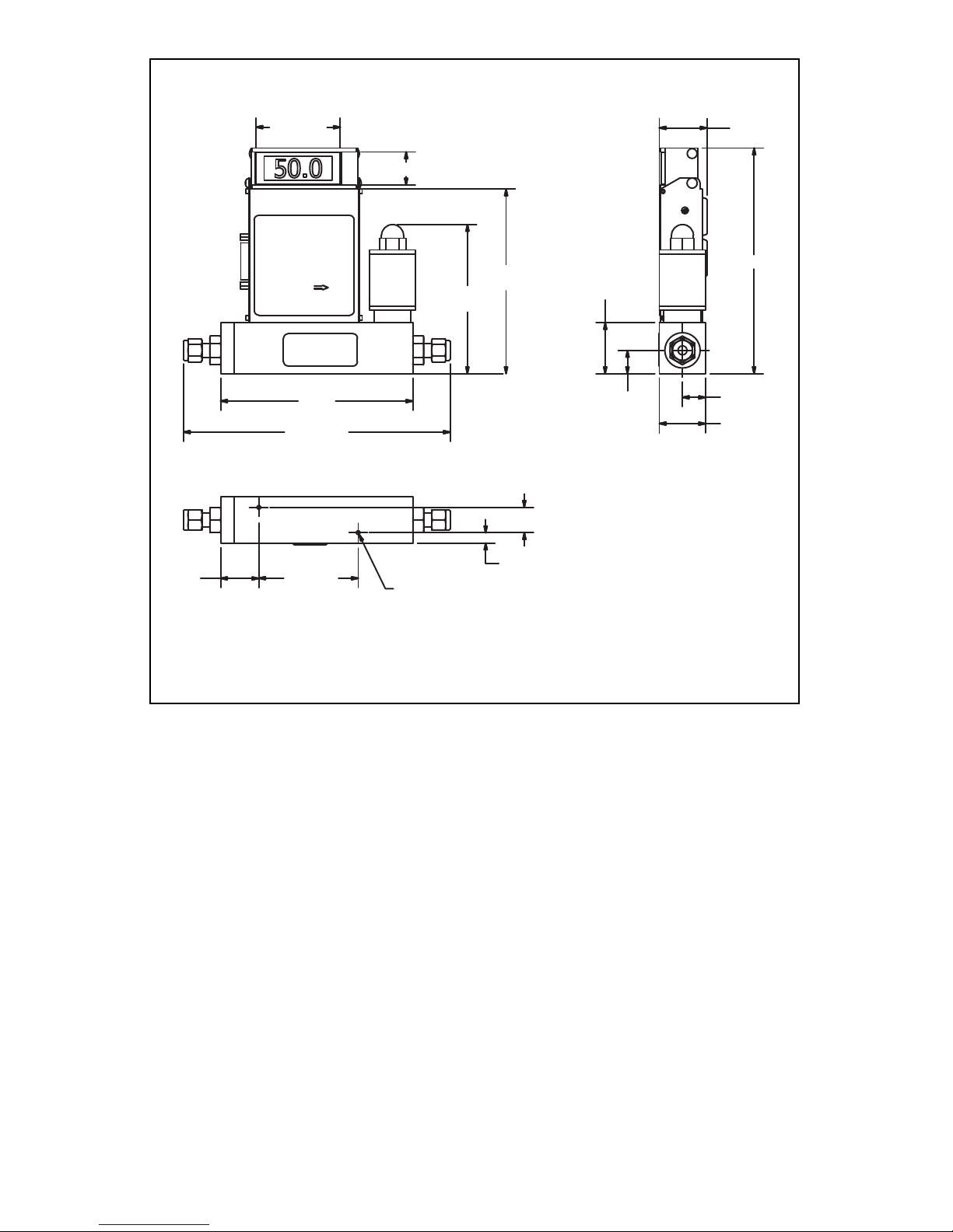
43
5.195
(132.0)
7.21 (183.1)
*7.33 (186.2)
2.38 (60.4)
0.95 (24.1)
4.03
(102.3)
4.99
(126.7)
1.25 (31.8)
0.63 (15.9)
0.63
(15.9)
1.29 (32.8)
6-32 UNC - 2B 0.09
0.28 (7.1)
0.69 (17.5)
6.10 (154.9)
1.38 (34.9)
1.03
(26.2)
2.69 (68.3)
SERIES MAX FLOW 15 - 100 L/min MASS FLOW CONTROLLER
NOTE: OMEGA reserves the right to change designs and dimensions at its sole discretion at any time
without notice. For cer tified dimensions please contact OMEGA.
Page 49
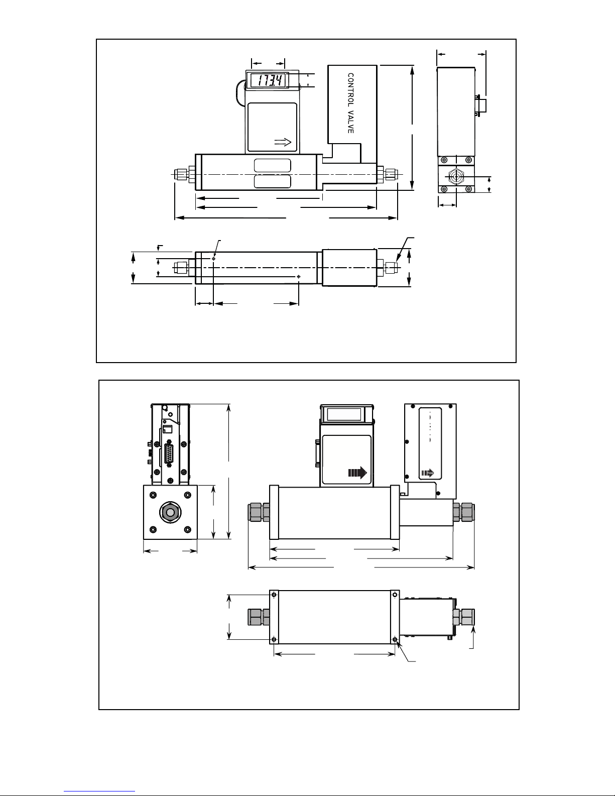
44
0.95
SAE/MS Swagelok
3/8 Tube Connector
2.38
7" (177,8)
9.98 (253,5)
12.30 (312,4)
* 10-24 UNC-2B
0.18 (4,6)
1.75 (44,5)
1.39 (35,3)
1" (25,4)
4.69 (119,1)
2.15 (54,6)
2.72 (69,1)
6.9" (175,3)
1" (25,4)
0.875 (22,2)
* For units purchased prior to August 15, 2012 thread size = 6-32 UNC-2B
SERIES MAX FLOW 200 L/min MASS FLOW CONTROLLER
NOTE: OMEGA reserves the right to change designs and dimensions at its sole discretion at any time
without notice. For cer tified dimensions please contact OMEGA.
50.00
l
(76,2 mm)
3.00
(76,2 mm)
3.00
(191,8 mm)
7.55
7.25 (184,1 mm)
10.24 (260,1 mm)
12.62 (320,5 mm)
(191,8 mm)
7.55
10.24 (260,1 mm)
12.62 (320,5 mm)
control
CE
flow
(63,5 mm)
2.50
6.75 (171,5 mm)
(63,5 mm)
2.50
August 15, 2012 thread size = 8-32 UNC-2B* For units purchased prior to
1/4-20 UNC-2B
*
2 x 1/2 compression fittings
August 15, 2012 thread size = 8-32 UNC-2B
SERIES MAX FLOW 500 L/min MASS FLOW CONTROLLER
Page 50
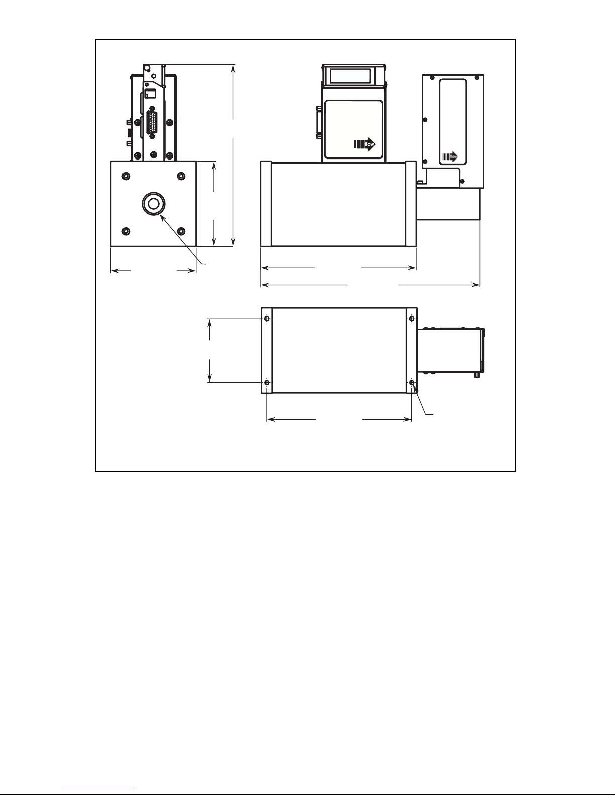
45
8.66
(219.9 mm)
4.00
(101,6 mm)
4.00 (101,6 mm)
3/4-14 NPT
(both sides)
10.28 (261,1 mm)
7.30 (185,4 mm)
3.00
(76,2 mm)
6.80 (172,7 mm)
1/4-20 UNC-2B
control
valve
CE
50.00
SERIES MAX FLOW 1000 L/min MASS FLOW CONTROLLER
NOTE: OMEGA reserves the right to change designs and dimensions at its sole discretion at any time
without notice. For cer tified dimensions please contact OMEGA.
Page 51

WARRANTY/DISCLAIMER
OMEGA ENGINEERING, INC. warrants this unit to be free of defects in materials and
workmanship for a period of 13 months from date of purchase. OMEGA’s WARRANTY adds an
additional one (1) month grace period to the normal one (1) year product warranty to cover
handling and shipping time. This ensures that OMEGA’s customers receive maximum coverage
on each product.
If the unit malfunctions, it must be returned to the factory for evaluation. OMEGA’s Customer
Service Department will issue an Authorized Return (AR) number immediately upon phone or
written request. Upon examination by OMEGA, if the unit is found to be defective, it will be
repaired or replaced at no charge. OMEGA’s WARRANTY does not apply to defects resulting
from any action of the purchaser, including but not limited to mishandling, improper interfacing,
operation outside of design limits, improper repair, or unauthorized modification. This
WARRANTY is VOID if the unit shows evidence of having been tampered with or shows
evidence of having been damaged as a result of excessive corrosion; or current, heat, moisture
or vibration; improper specification; misapplication; misuse or other operating conditions
outside of OMEGA’s control. Components in which wear is not warranted, include but are not
limited to contact points, fuses, and triacs.
OMEGA is pleased to offer suggestions on the use of its various products. However,
OMEGA neither assumes responsibility for any omissions or errors nor assumes liability for any
damages that result from the use of its products in accordance with information provided by
OMEGA, either verbal or written. OMEGA warrants only that the parts manufactured by the
company will be as specified and free of defects. OMEGA MAKES NO OTHER WARRANTIES OR
REPRESENTATIONS OF ANY KIND WHATSOEVER, EXPRESSED OR IMPLIED, EXCEPT THAT OF
TITLE, AND ALL IMPLIED WARRANTIES INCLUDING ANY WARRANTY OF MERCHANTABILITY
AND FITNESS FOR A PARTICULAR PURPOSE ARE HEREBY DISCLAIMED. LIMITATION OF
LIABILITY: The remedies of purchaser set forth herein are exclusive, and the total liability of
OMEGA with respect to this order, whether based on contract, warranty, negligence,
indemnification, strict liability or otherwise, shall not exceed the purchase price of the
component upon which liability is based. In no event shall OMEGA be liable for consequential,
incidental or special damages.
CONDITIONS: Equipment sold by OMEGA is not intended to be used, nor shall it be used: (1) as
a “Basic Component” under 10 CFR 21 (NRC), used in or with any nuclear installation or activity;
or (2) in medical applications or used on humans. Should any Product(s) be used in or with any
nuclear installation or activity, medical application, used on humans, or misused in any way,
OMEGA assumes no responsibility as set forth in our basic WARRANTY/ DISCLAIMER language,
and, additionally, purchaser will indemnify OMEGA and hold OMEGA harmless from any liability
or damage whatsoever arising out of the use of the Product(s) in such a manner.
RETURN REQUESTS/INQUIRIES
Direct all warranty and repair requests/inquiries to the OMEGA Customer Service Department.
BEFORE RETURNING ANY PRODUCT(S) TO OMEGA, PURCHASER MUST OBTAIN AN AUTHORIZED
RETURN (AR) NUMBER FROM OMEGA’S CUSTOMER SERVICE DEPARTMENT (IN ORDER TO AVOID
PROCESSING DELAYS). The assigned AR number should then be marked on the outside of the return
package and on any correspondence.
The purchaser is responsible for shipping charges, freight, insurance and proper packaging to
prevent breakage in transit.
FOR WARRANTY
RETURNS, please have the
following information available BEFORE
contacting OMEGA:
1. Purchase Order number under which
the product was PURCHASED,
2. Model and serial number of the product
under warranty, and
3. Repair instructions and/or specific
problems relative to the product.
FOR NON-WARRANTY REPAIRS,
consult OMEGA
for current repair charges. Have the following
information available BEFORE contacting OMEGA:
1. Purchase Order number to cover the
COST of the repair,
2. Model and serial number of theproduct, and
3. Repair instructions and/or specific problems
relative to the product.
OMEGA’s policy is to make running changes, not model changes, whenever an improvement is possible.
This affords our customers the latest in technology and engineering.
OMEGA is a registered trademark of OMEGA ENGINEERING, INC.
© Copyright 2009 OMEGA ENGINEERING, INC. All rights reserved. This document may not be copied, photocopied, repro-
duced, translated, or reduced to any electronic medium or machine-readable form, in whole or in part, without the prior written consent of OMEGA ENGINEERING, INC.
46
Page 52

M-5372/0318
Where Do I Find Everything I Need for
Process Measurement and Control?
OMEGA… Of Course!
Shop online at omega.com
SM
TEMPERATURE
䡺⻬
Thermocouple, RTD & Thermistor Probes, Connectors, Panels & Assemblies
䡺⻬
Wire: Thermocouple, RTD & Thermistor
䡺⻬
Calibrators & Ice Point References
䡺⻬
Recorders, Controllers & Process Monitors
䡺⻬
Infrared Pyrometers
PRESSURE, STRAIN AND FORCE
䡺⻬
Transducers & Strain Gages
䡺⻬
Load Cells & Pressure Gages
䡺⻬
Displacement Transducers
䡺⻬
Instrumentation & Accessories
FLOW/LEVEL
䡺⻬
Rotameters, Gas Mass Flowmeters & Flow Computers
䡺⻬
Air Velocity Indicators
䡺⻬
Turbine/Paddlewheel Systems
䡺⻬
Totalizers & Batch Controllers
pH/CONDUCTIVITY
䡺⻬
pH Electrodes, Testers & Accessories
䡺⻬
Benchtop/Laboratory Meters
䡺⻬
Controllers, Calibrators, Simulators & Pumps
䡺⻬
Industrial pH & Conductivity Equipment
DATA ACQUISITION
䡺⻬
Data Acquisition & Engineering Software
䡺⻬
Communications-Based Acquisition Systems
䡺⻬
Plug-in Cards for Apple, IBM & Compatibles
䡺⻬
Datalogging Systems
䡺⻬
Recorders, Printers & Plotters
HEATERS
䡺⻬
Heating Cable
䡺⻬
Cartridge & Strip Heaters
䡺⻬
Immersion & Band Heaters
䡺⻬
Flexible Heaters
䡺⻬
Laboratory Heaters
ENVIRONMENTAL
MONITORING AND CONTROL
䡺⻬
Metering & Control Instrumentation
䡺⻬
Refractometers
䡺⻬
Pumps & Tubing
䡺⻬
Air, Soil & Water Monitors
䡺⻬
Industrial Water & Wastewater Treatment
䡺⻬
pH, Conductivity & Dissolved Oxygen Instruments
 Loading...