

Page 1

Model FLSC-C3-XX
DC Powered Microprocessor
Controlled Transmitter
Page 2

Page 3

CONTENTS
1. Introduction----------------------------------------------------------------- 2
2. Specifications --------------------------------------------------------------- 4
3. Installation and Operation----------------------------------------------- 5
3.1. Power Supply --------------------------------------------------------- 5
3.2. Flowmeter Input ------------------------------------------------------ 6
3.3. Pulse Output----------------------------------------------------------- 8
3.4. Analog Output ------------------------------------------------------- 10
3.5 Alarm Outputs ------------------------------------------------------- 12
3.6. Communications Connections ------------------------------------- 14
3.7. Wiring----------------------------------------------------------------- 14
Appendix A – Default Configuration --------------------------------------15
-1-
Page 4
H
P
A
P
C
P
P
A
O
P
LOWA
C
L
I
C
1. Introduction
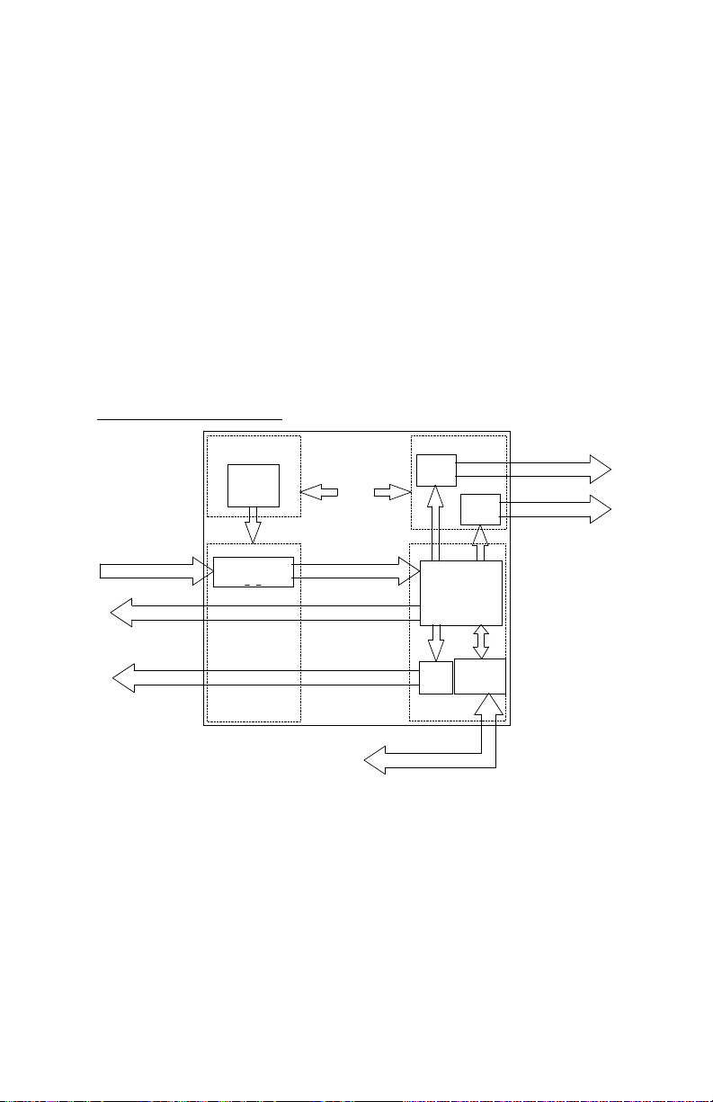
The FLSC-C3 is a versatile DC powered microprocessor-based
transmitter, which provides pulse output, analog output and an optional
Low flow alarm option.
The flowmeter input circuitry will accept a variety of signal types
including, low level sinusoidal, MCP/RF, pulse and contact closure.
Optional 20-point linearization is available to correct for flowmeter
non-linearities, improving overall system accuracy. The FLSC-C3 is
compatible with many Omega turbine flowmeters as well as the
FTB3000 series positive displacement flowmeters.
FLSC-C3 Block Diagram
PULSE OUT
ANALOG OUT
FLOWMETER INPUT
CA182
C/DC
ONVERTER
REAMP
CA180
ONDITIONED SIGNAL
R
ULSE OUT
NALOG OUT
CA184
HIGH
ALARM
LARM
MICROCONTROLLER
OM
DAC
NTERFACE
PCA183
RS232
IGH ALARM OUT
OW ALARM OUT
An RS232 communications port located under the top plate allows
FLSC-C3 to be remotely configured using a Windows based
application that is included with all units.
-2-
Page 5

The standard unit is packaged in an extruded aluminum enclosure for
wall mounting or may be mounted directly on FTBG Series Turbine
optional NEMA 4X or EX enclosure. An optional bracket is also
available for mounting on standard DIN rail.
-3-
Page 6

2. Specifications
General Specifications
Input Signal Type: Magnetic pick up, MCP pick up, Contact
Closure, Pulse
Input frequency range: 0.2 Hz to 4 KHz
Signal level: 10 mV rms to 30 Vdc
Power supply: 8-30 Vdc (Reverse polarity protected)
100-240 Vac (Fuse rating 0.5A, 250 Vac)
optional
Analog Output: 4-20mA, 1-5V
Load resistance: Max 650 Ohms at 24 Vdc
Accuracy: +/- 0.02% of full scale @ 20 C
Temperature drift: 40ppm/deg C
Pulse output 0-5, 0-10V*, Open Collector, AC square
*Requires 12-30 Vdc Power Supply
Internal pull-up resistor 10k Ohms
Recommended load min. 50k Ohms
Pulse Scaling Per flow unit of measure, divide by 1, 10, 100
Hi/Lo Alarm Relay (2A, 30 Vdc), 0-5V, Open Collector
(0.5A, 30 Vdc)
Communications RS232 port for Configuration and
diagnostics
Operating temperature: -40 to 85 C
Humidity: 0-90% Non-condensing
Enclosure: Extruded aluminum, DIN rail mount, or
Explosion Proof
Regulatory: CE compliant
Options
20 point linearization
o
-4-
Page 7
3. Installation and Operation
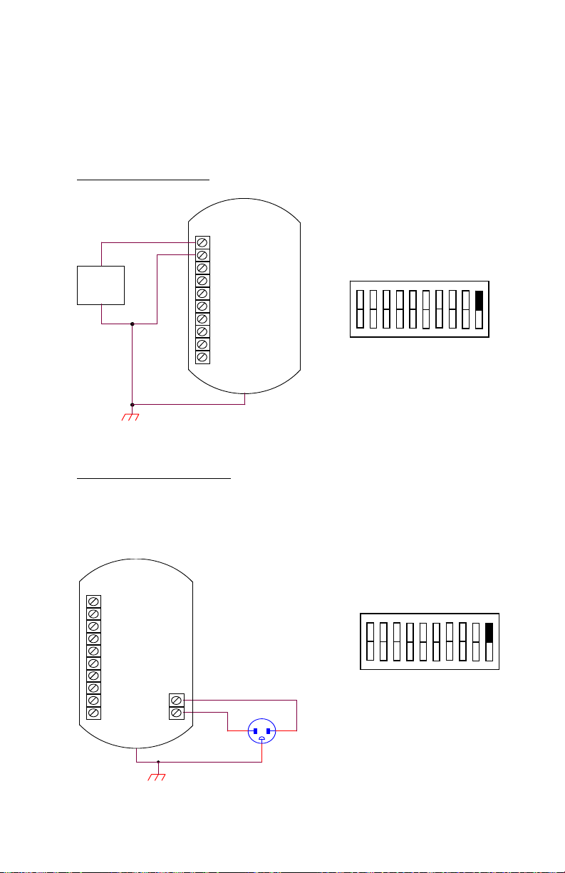
3.1. Power Supply
DC Power (8-30 VDC)
DC+
+
DC
POWER
SUPPLY
-
AC Power (100-240 VAC)
AC power for FLSC-C3 requires an optional circuit board, PCA182. The
Alarm option (PCA184) is not available when the AC Power option is
equipped.
DCSIG+
SIGANLG
PULSE+
PULSEN/C
N/C
N/C
1
PCA180
SW2
DC+
DCSIG+
SIGANLG
PULSE+
PULSEN/C
N/C
N/C
1
L1
L2
PLUG AC MALE
NEUTRAL HOT
-5-
PCA180
SW2
Page 8
3.2. Flowmeter Input
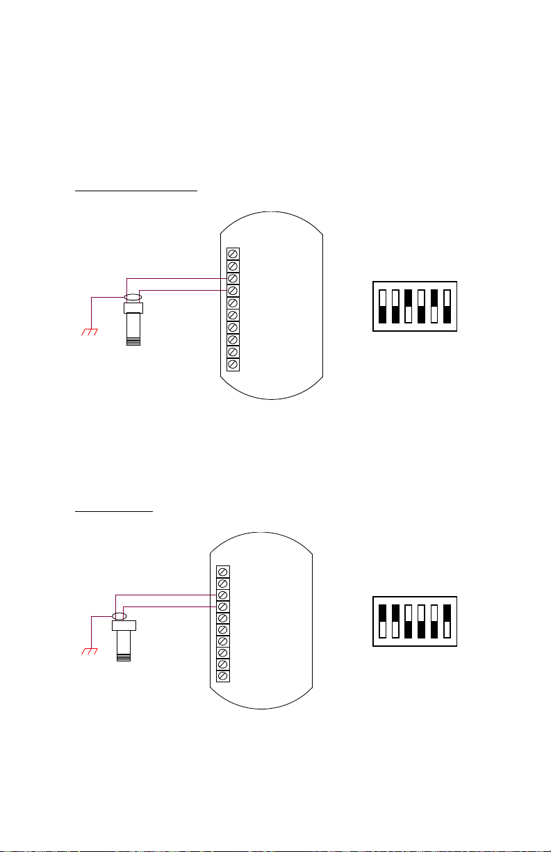
The Preamp circuitry for conditioning the flow signal is located on PCA180.
The following drawings illustrate typical connections and switch settings on
PCA180 for various input signals.
Magnetic Pickup Coil
DC+
DC-
SIG+
A B
Mag Pickup Coil
SIGANLG
PULSE+
PULSEN/C
N/C
N/C
1
PCA180
SW1
MCP/RF Coil
A B
C
Modulated Carrier Pickup (RF)
DC+
DCSIG+
SIGANLG
PULSE+
PULSEN/C
N/C
N/C
1
PCA180
SW1
-6-
Page 9
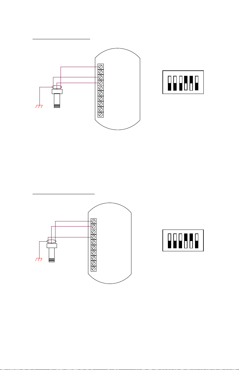
Redi-Pulse (TTL Pulse)
BA
C
Redi-Pulse (TTL) Pickup Coil
Redi-Pulse (Open Collector)
DC+
DCSIG+
SIGANLG
PULSE+
PULSEN/C
N/C
N/C
1
PCA180
SW1
AB
C
Redi-Pulse (Open Collector)
Pickup Coil
DC+
DCSIG+
SIGANLG
PULSE+
PULSEN/C
N/C
N/C
-7-
1
PCA180
SW1
Page 10
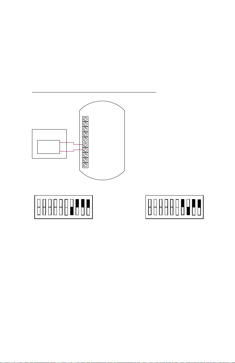
3.3. Pulse Output
FLSC-C3 provides a Pulse Output option that is scaled per flow unit of
measure by a factor of 1, 10 or 100. The following drawings illustrate
typical connections and switch settings for various pulse output
options.
TTL(0-5V), 0-10V, High Level (DC In), AC Square
DC+
DC-
SIG+
USER DCS
PULSE
INPUT
+
-
SIGANLG
PULSE+
PULSEN/C
N/C
N/C
1
TTL(0-5V), 0-10V, AC Square
PCA180
SW2
1
PCA180
SW2
High Level Pulse, AC Square
-8-
Page 11
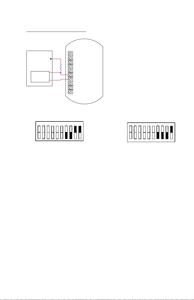
Open Collector, Isolated Pulse
USER DCS
PULSE
INPUT
V+
2.7K
+
-
DC+
DCSIG+
SIGANLG
PULSE+
PULSEN/C
N/C
N/C
1
PCA180
SW2
Open Collector
1
PCA180
SW2
Isolated Pulse
-9-
Page 12
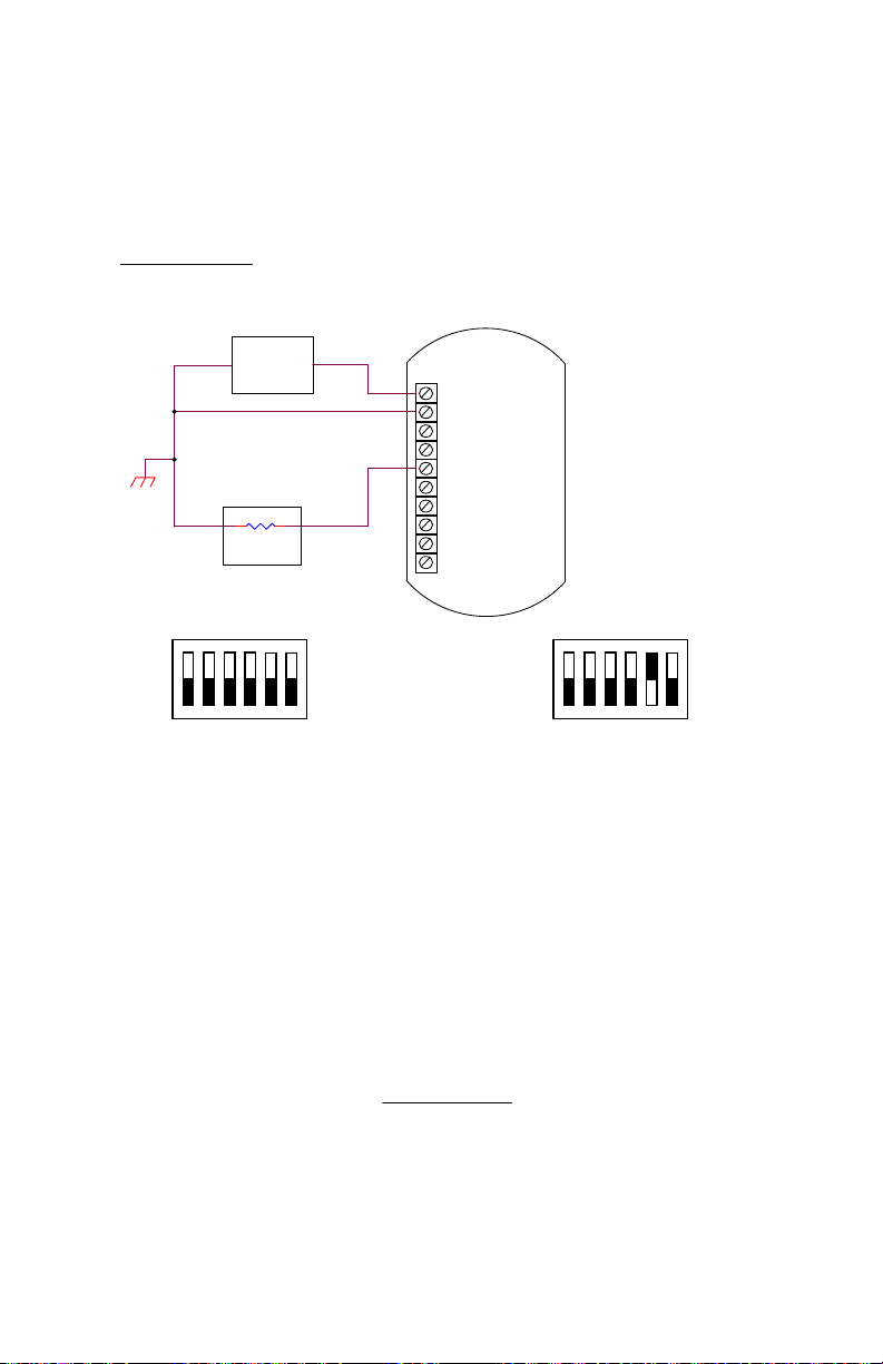
3.4. Analog Output
FLSC-C3 provides an Analog Output option that will output an analog
current or voltage that is proportional to the flow rate.
Analog Output
DC
POWER
SUPPLY
LOAD
+
DC+
DCSIG+
SIGANLG
PULSE+
+
PULSEN/C
N/C
N/C
1
4–20 mA Output
PCA183
SW1
1
PCA183
SW1
1-5 V Output
The Microcontroller, located on PCA183, accepts the squarewave output of the preamplifier and performs all of the
calculations that are required to control the Loop Driver. After
measuring the frequency of the square-wave, the Microcontroller
uses the following equations to compute the flow rate and current.
flowrate
frequency
FM
xCFx
60
Kfactor
-10-
Page 13

Where:
Kfactor = Is dependent on the Flow Calculation Method setting and
is either the Average K-Factor or the Linearized KFactor from the Frequency / K-Factor table.
FM = Is the Flow rate Units setting of 0, 1, or 2. Where “0” is
for Seconds, “1” is for Minutes, and “2” is for Hours.
CF = Is the Correction Factor setting.
mAxmAcurrent 164
flowrate
AF
Where:
AF = Is the 20 mA maximum Flow rate value.
If the calculated flowrate is greater than the AF setting, the
current will be set to 24mA to indicate an “Over-range” condition.
After calculating the current, the Microcontroller digitally sends
the current information to the Loop Driver. The loop driver,
located on PCA183, uses the digital information sent to it by the
Microcontroller to set the current of the loop. The Loop Driver
also supplies power to the Microcontroller.
The analog output response time to reach steady state due to a
change in the flow rate is approximately two (1/8) seconds. When
flow stops, the time for the analog output to return to 4 mA will
be between 3 and 12 seconds, depending on the Maximum
Sample Time (MST) setting. MST is adjusted using the NB=
(DATA) command, where NB is a value between 1 and 80. The
default MST setting is NB= 1. Adjusting the MST is only
recommended for low flow applications where the minimum input
frequency is below 1 Hz.
-11-
Page 14
H
d
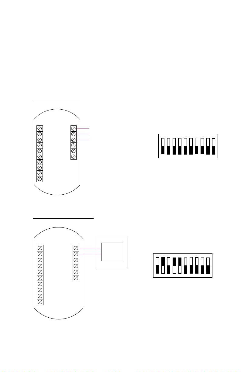
3.5. Alarm Outputs
FLSC-C3 provides an optional High/Low Flow Alarm feature. Alarms
require an optional circuit board, PCA184. The Alarm option is not
available on AC Power units. The drawings below illustrate the typical
connections and switch settings for various alarm options.
Hi/Lo Alarm Relay
DC+
DC-
SIG+
SIGANLG
PULSE+
PULSEN/C
N/C
N/C
NC1
COM1
NO1
Hi/Lo Alarm TTL(0-5V)
DC+
ALARM1
DCSIG+
SIGANLG
PULSE+
PULSEN/C
N/C
N/C
COM
igh/Low-Nomally Close
High/Low-COM
High/Low-Nomally Open
USER DCS
+
Alarm
Indicator
-
1
1
PCA184
SW1
PCA184
SW1
-12-
Page 15
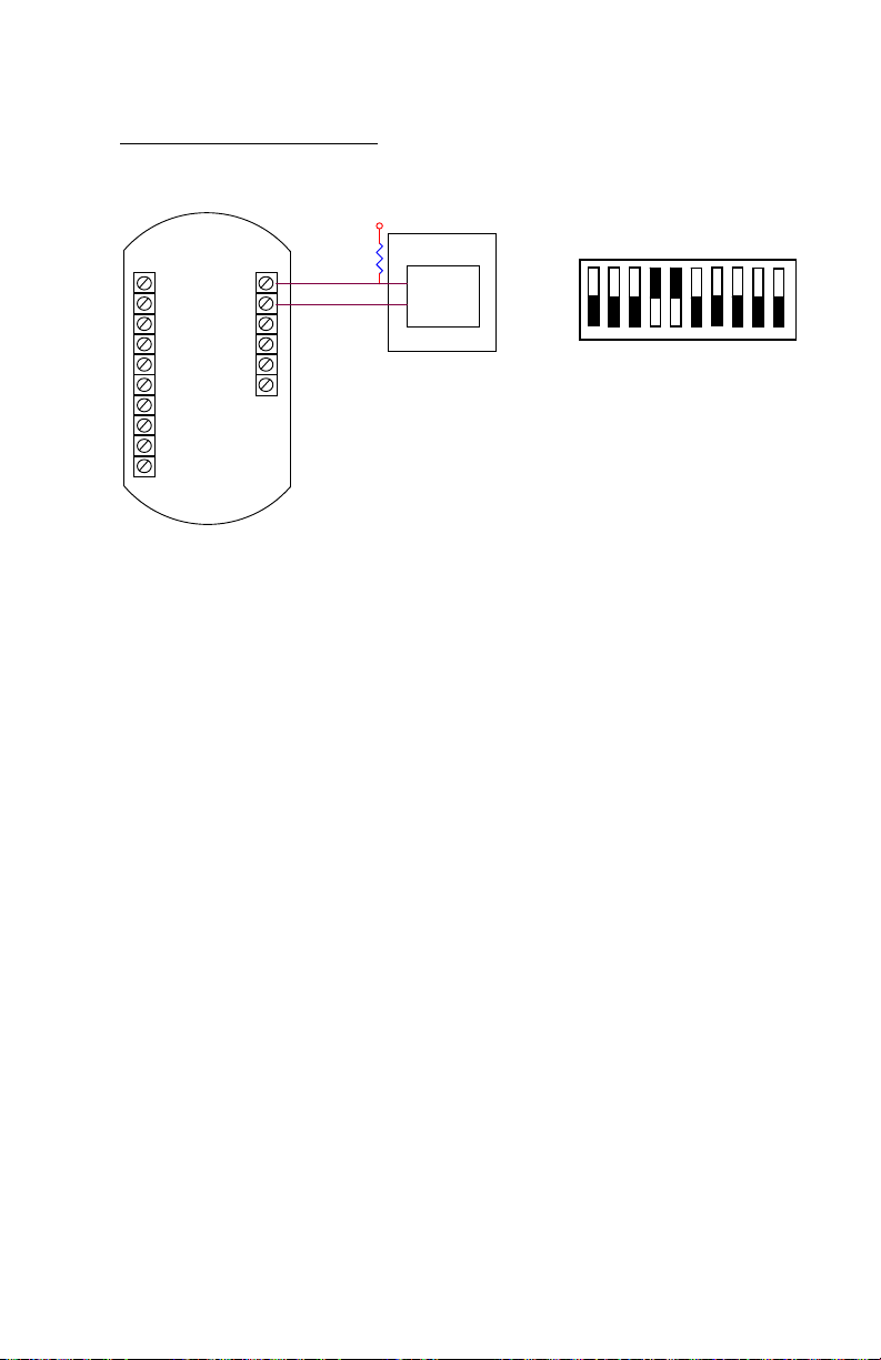
Hi/Lo Alarm Open Collector
DC+
DC-
SIG+
SIGANLG
PULSE+
PULSEN/C
N/C
N/C
ALARM1
COM
2.7K
V+
USER DCS
+
Indicator
-
Alarm
1
PCA184
SW1
-13-
Page 16
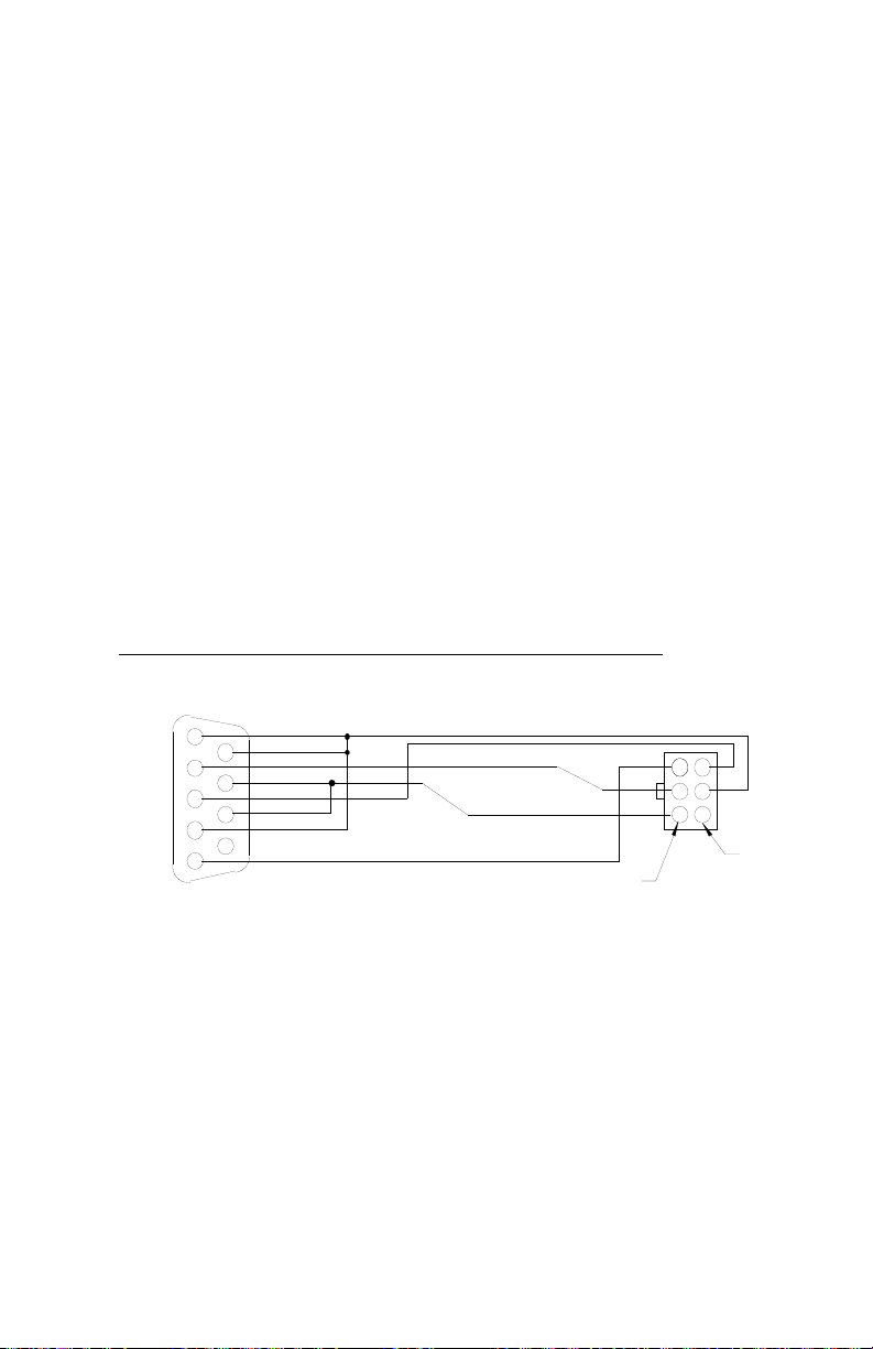
3.6. Communications Connections
FLSC-C3 is equipped with RS232 serial Communication port for changing
FLSC-C3 configuration, diagnostic functions, and flow monitoring. Omega
communication program DevConfig must be used to communicate with
FLSC-C3.
The RS232 serial port connector is located under the top plate of FLSC-C3
and may be accessed by removing the two screws from the top plate. A
matching connector is provided with OMEGA FLSC-C-CABLE
Communications Cable. FLSC-C3 unit has to be powered from external
supply in order to be able to communicate. Additional power for FLSC-C3
communication circuitry is supplied by the RS232 serial port of the
computer/terminal. COM port settings must be set as follows:
Baud Rate: 2400
Data Bits: 8
Parity: None
Stop bits: 1
Handshaking: None
OMEGA FLSC-C-CABLE Communications Cable
Molex
Pin 1
0511100660
or
Equivalent
CD 1
Rx 2
Tx 3
DTR 4
SIG COM 5
DB9
6 DSR
7 RTS
8 CTS
9 NC
VDC1
VDC2
Pin 2
3.7. Wiring
When installing FLSC-C3, it is a good practice to use shielded cables for all
input and output signals. The shield should be connected to the earth
ground lug on the FLSC-C3. The shield on the opposite end of the cable
should be left open.
This wiring practice is mandatory in order to comply with the requirements
for Electromagnetic Compatibility, as per EMC-Directive 89/336/EEC of
the Council of European Community.
-14-
Page 17

Appendix A – Default Configuration
Factory default configuration:
FIELD Value
FLOW CALC. METHOD 0 (Average)
K-FACTOR DECIMAL 3
AVERGAE K-FACTOR 1.00
NUMBER OF POINTS IN K-TABLE 12
FREQUENCY 01 4999.981
FREQUENCY 02 4999.982
FREQUENCY 03 4999.983
FREQUENCY 04 4999.984
FREQUENCY 05 4999.985
FREQUENCY 06 4999.986
FREQUENCY 07 4999.987
FREQUENCY 08 4999.988
FREQUENCY 09 4999.989
FREQUENCY 10 4999.990
FREQUENCY 11 4999.991
FREQUENCY 12 4999.992
FREQUENCY 13 4999.993
FREQUENCY 14 4999.994
FREQUENCY 15 4999.995
FREQUENCY 16 4999.996
FREQUENCY 17 4999.997
FREQUENCY 18 4999.998
FREQUENCY 19 4999.999
FREQUENCY 20 5000.000
K-FACTOR 01 1.00
K-FACTOR 02 1.00
K-FACTOR 03 1.00
K-FACTOR 04 1.00
K-FACTOR 05 1.00
K-FACTOR 06 1.00
K-FACTOR 07 1.00
K-FACTOR 08 1.00
K-FACTOR 09 1.00
K-FACTOR 10 1.00
K-FACTOR 11 1.00
K-FACTOR 12 1.00
K-FACTOR 13 1.00
K-FACTOR 14 1.00
K-FACTOR 15 1.00
K-FACTOR 16 1.00
-15-
Page 18

K-FACTOR 18 1.00
K-FACTOR 19 1.00
K-FACTOR 20 1.00
MEASURING UNITS GAL
FLOW RATE TIME UNITS MIN
MAX SAMPLE TIME 01
ANALOG OUTPUT LOW 00000.000
ANALOG OUTPUT HIGH 99.999
PULSE SCALE OFF
PULSE FREQUENCY 100
ALARM FUNCTION Off
ALARM LEVEL 99999.981
-16-
Page 19

-17-
Page 20

-18-
M-5131/0317
 Loading...