

Page 1
www.omega.com
e-mail: [email protected]
User’s Guide
FLSC90-A
Fiber Optic Flow Transmitter
Shop online at
MADE IN
Page 2

Servicing North America:
USA: One Omega Drive, P.O. Box 4047
ISO 9001 Certified Stamford CT 06907-0047
TEL: (203) 359-1660 FAX: (203) 359-7700
e-mail: [email protected]
Canada: 976 Bergar
Laval (Quebec) H7L 5A1, Canada
TEL: (514) 856-6928 FAX: (514) 856-6886
e-mail: [email protected]
For immediate technical or application assistance:
USA and Canada: Sales Service: 1-800-826-6342 / 1-800-TC-OMEGA
®
Customer Service: 1-800-622-2378 / 1-800-622-BEST
®
Engineering Service: 1-800-872-9436 / 1-800-USA-WHEN
®
TELEX: 996404 EASYLINK: 62968934 CABLE: OMEGA
Mexico: En Espan˜ol: (001) 203-359-7803 e-mail: [email protected]
FAX: (001) 203-359-7807 [email protected]
Servicing Europe:
Benelux: Postbus 8034, 1180 LA Amstelveen, The Netherlands
TEL: +31 (0)20 3472121 FAX: +31 (0)20 6434643
Toll Free in Benelux: 0800 0993344
e-mail: [email protected]
Czech Republic: Frystatska 184, 733 01 Karviná, Czech Republic
France: 11, rue Jacques Cartier, 78280 Guyancourt, France
TEL: +33 (0)1 61 37 2900 FAX: +33 (0)1 30 57 5427
Toll Free in France: 0800 466 342
e-mail: [email protected]
Germany/Austria: Daimlerstrasse 26, D-75392 Deckenpfronn, Germany
TEL: +49 (0)7056 9398-0 FAX: +49 (0)7056 9398-29
Toll Free in Germany: 0800 639 7678
e-mail: [email protected]
United Kingdom: One Omega Drive, River Bend Technology Centre
ISO 9002 Certified Northbank, Irlam, Manchester
M44 5BD United Kingdom
TEL: +44 (0)161 777 6611 FAX: +44 (0)161 777 6622
Toll Free in United Kingdom: 0800-488-488
e-mail: [email protected]
OMEGAnet®Online Service Internet e-mail
www.omega.com [email protected]
It is the policy of OMEGA to comply with all worldwide safety and EMC/EMI regulations that
apply. OMEGA is constantly pursuing certification of its products to the European New Approach
Directives. OMEGA will add the CE mark to every appropriate device upon certification.
The information contained in this document is believed to be correct, but OMEGA Engineering, Inc. accepts
no liability for any errors it contains, and reserves the right to alter specifications without notice.
WARNING: These products are not designed for use in, and should not be used for, human applications.
Page 3

i
Table of Contents
Section ........................................................................... Page
Section 1 General Description ........................................................................ 1
Section 2 Unpacking ........................................................................................ 1
Section 3 Theory of Operation ....................................................................... 2
Section 4 Mounting .......................................................................................... 3
Section 5 Fiber Optic Sensor/Cable Installation ......................................... 5
Section 6 Using The Fiber Optic Extension Cable (FLSC90-CA9) ............ 6
Section 7 Electrical Power/Output Connection........................................... 7
Section 8 Transmitter Scaling ......................................................................... 9
Section 9 Maintenance ................................................................................... 10
Section 10 Specifications ................................................................................. 11
FLSC90-A FIBER OPTIC FLOW TRANSMITTER
Page 4

ii
Table of Figures
Figure Description: ......................................................... Page:
1. Basic System Setup ...................................................................................... 2
2. Mounting Dimensions ................................................................................ 3
3. Basic Connections ........................................................................................ 3
4. Enclosure To Earth Ground Cable Connection ....................................... 4
5. Sensor Cable/Fitting Installation .............................................................. 5
6. Sensor Cable Installation ............................................................................ 5
7. Current Output ............................................................................................ 7
8. Voltage Output ............................................................................................. 7
9. Calibration Setup........................................................................................ 10
FLSC90-A FIBER OPTIC FLOW TRANSMITTER
Page 5

1
Section 1 - General Description
The OMEGA®FLSC90-A Fiber Optic Flow Signal Conditioner/Transmitter has
been designed for use with the patented LIGHTSPEED
TM
Paddlewheel flow
Sensors and will provide a linearized output signal of 4 to 20 mAor 1 to 5 Vdc.
The output signal is scaled and directly proportional to the rate of flow
measured by the paddlewheel sensor when installed in a FP9000 SERIES
installation fitting. The transmitter is mounted in a die cast aluminum housing
(NEMA4 rated).
Section 2 - Unpacking
Remove the packing list and verify that you have received all your equipment. If
you have any questions about the shipment, please call our Customer Service
Department at
1-800-622-2378 or 203-359-1660. We can also be reached on the Internet at
www.omega.com
e-mail: [email protected]
When you receive the shipment, inspect the container and equipment for any
signs of damage. Note any evidence of rough handling in transit. Immediately
report any damage to the shipping agent.
The carrier will not honor any damage claims unless all shipping material is saved for
inspection. After examining and removing contents, save packing material and carton in the
event reshipment is necessary.
The following following items are supplied in the box with your FLAC90-A.
• This Manual, #M-3586 (1 ea.)
• Fiber Optic Cable Sealing Washer (2 ea.)
• 249 Ohm Shunt Resister For Voltage Output Operation (1 ea.)
NOTE:
FLSC90-A FIBER OPTIC FLOW TRANSMITTER
Page 6
Section 3 - Theory of Operation
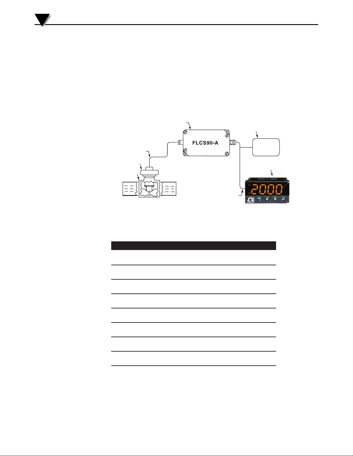
The FLSC90-A has been designed to interface directly with OMEGA’s FP9000
Series LIGHTSPEED
TM
Paddlewheel flow sensors. The FLSC90-A signal
conditioner/transmitter provides a high intensity light source to the patented
paddlewheel flow sensor through a semi-rigid, duplex, fiber optic cable.
Returning light pulses are measured and converted by the signal conditioner to
an analog output current or voltage output that is directly proportional to the
flow rate being measured by the paddlewheel.
Figure 1 - Basic System Setup
Paddlewheel Flow Sensor: Use Model: FP9001 for pipe/fitting sizes 1/2" to 3"
Installation Fittings Available: see table below
Model No. Pipe Size Flow Range (GPM)
FP9005
1
⁄2" 1.0 - 20
FP9007
3
⁄4" 2.0 - 30
FP9010 1" 4.0 - 55
FP9012 1 1⁄4" 4.5 - 90
FP9015 1 1⁄2" 8.0 - 125
FP9020 2" 15 - 200
FP9025 2 1⁄2" 20 - 300
FP9030 3" 25 - 500
Complimentary Instruments
Power Supply, OMEGA
®
Model No.: PSU-93
OMEGA
®
iSeries Panel Meters and Controllers
Accessories
Shielded Transmitter Cable, OMEGA
®
Model No.: TX4-100 (100 ft)
Fiber Optic Extension Cable, OMEGA
®
Model No.: FLSC90-CA9
FLSC90-A FIBER OPTIC FLOW TRANSMITTER
2
SIGNAL CONDITIONER
DC POWER SUPPLY
PROCESS PANEL METER
TX4-100 CABLE
FLOW LINE FITTING
PADDLEWHEEL SENSOR
FIBER-OPTIC CABLE
PSU-93
Model DPi8
or i Series
Panel Meter
Page 7
Section 4 – Mounting
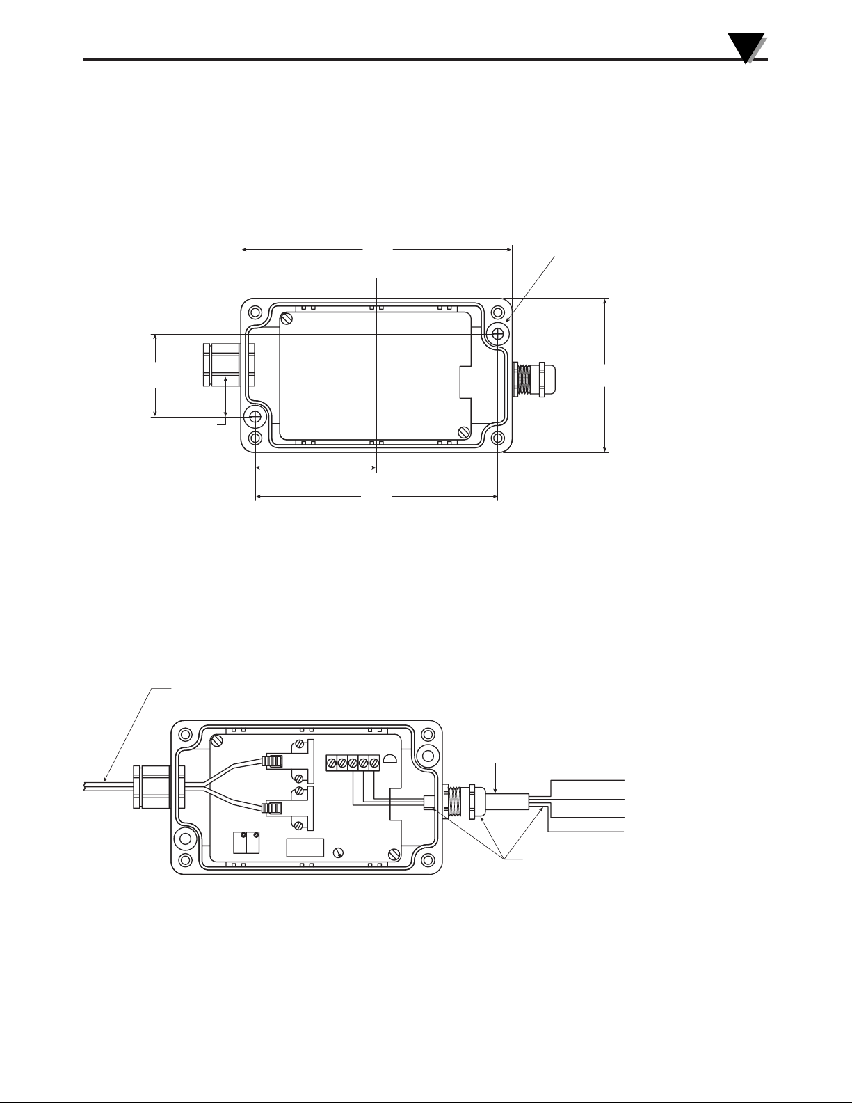
The FLSC90-A is mounted by using the internal mounting holes located inside
the aluminum enclosure with the lid removed. Refer to figure below for
mounting dimensions.
Figure 2 - Mounting Dimensions, mm (inches)
Figure 3 - Basic Connections
FLSC90-A FIBER OPTIC FLOW TRANSMITTER
3
115.3
(4.54)
C
L
MOUNTING HOLE (2 PLACES)
FOR #6 SCREW/BOLT
35
C
L
(1.38)
17.5
(.69)
51.3
(2.02)
DUPLEX FIBER OPTIC CABLE
FROM FP-9000 SERIES PADDLEWHEEL SENSOR
2
1
65.3
(2.57)
102.6
(4.04)
TX-4 CABLE
3
5
4
BLACK WIRE
WHITE WIRE
RED WIRE
BARE WIRE
- POWER SUPPLY
4-20 mA / 1-5Vdc OUTPUT
+ POWER SUPPLY
EARTH GROUND
SEE DETAIL "A"
Page 8
Maintaining Electrical Noise Immunity
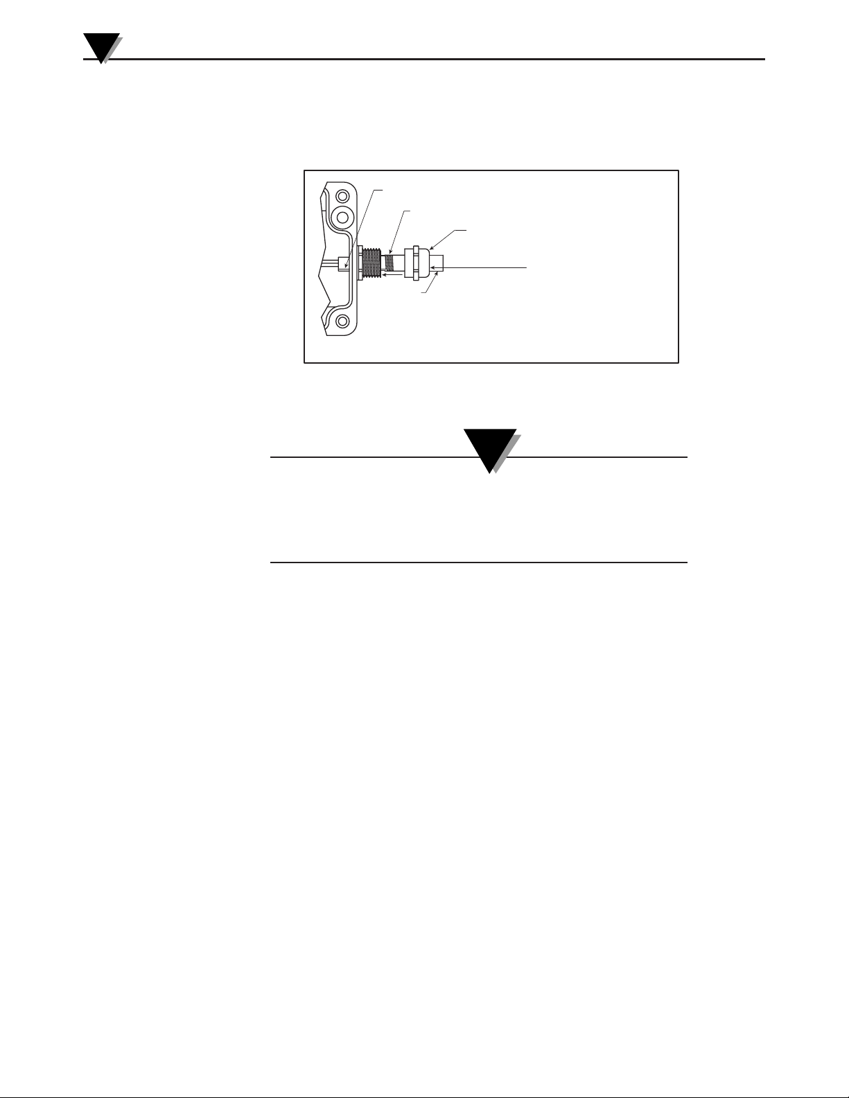
Figure 4 - Enclosure To Earth Ground Cable Connection
To maintain proper electrical noise immunity the shielded
cable bare wire must be securley fastened to the enclosure
housing as shown above. The other end of the cables bare
wire must be connected to earth ground.
FLSC90-A FIBER OPTIC FLOW TRANSMITTER
4
DETAIL “A” ENCLOSURE TO EARTH GROUND CABLE CONNECTION
NOTE:
DETAIL "A" - ENCLOSURE TO EARTH GROUND CABLE CONNECTION
FOLD BARE WIRE BACK THROUGH FITTING
BARE WIRE SEE NOTE
STRAIN RELIEF CAP
TX4 CABLE
BARE WIRE
NOTE:
WRAP THE BARE WIRE AROUND THE OUTER
CABLE DIAMETER AND SECURE STRAIN
RELIEF CAP TO CREATE A SOLID EARTH
GROUND CONNECTION TO THE ENCLOSURE
EARTH GROUND
Page 9
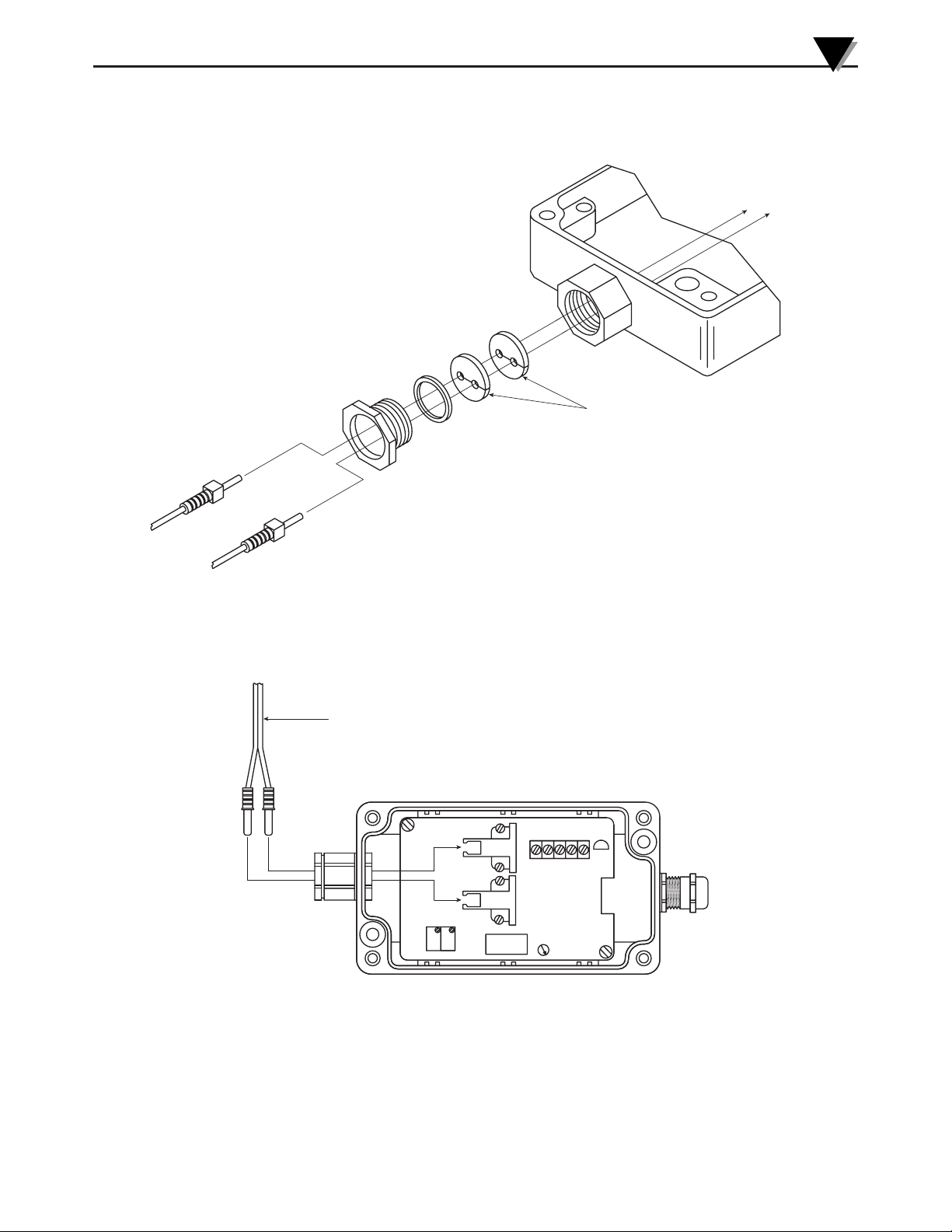
Section 5 – Fiber Optic Sensor/Cable Installation
Figure 5 - Sensor Cable/Fitting Installation
Figure 6 - Sensor Cable Installation
FLSC90-A FIBER OPTIC FLOW TRANSMITTER
5
FIBER OPTIC CABLE
SEALING WASHER
DUPLEX FIBER OPTIC CABLE
FROM FP-9000 SERIES PADDLEWHEEL SENSOR
25
1
34
Page 10

Section 6 – Using the Fiber Optic Extension Cable (FLSC90-CA9)
Where in applications such, that the fiber optic sensor must be installed farther
than the attached duplex cable on the sensor will allow, an extension cable is
available (Omega Model No. FLSC90-CA9. This accessory extends the total
overall distance between the paddlewheel sensor and the signal conditioner to
18'. It is not recommended that more than one extension cable be used in your
application. The farther the fiber optic cable is extended, the less the sensors
ability to return light pulses that are high enough in amplitude for the signal
conditioner to process.
When measuring the flow of dirty, discolored, or cloudy liquids such as, oil, ink, milk or others, if possible, the sensor cable should not be extended beyond the standard 9 feet and may also require to be
shortened for proper operation in such applications.
FLSC90-A FIBER OPTIC FLOW TRANSMITTER
6
NOTE:
Page 11
Section 7 – Electrical Power/Output Connection
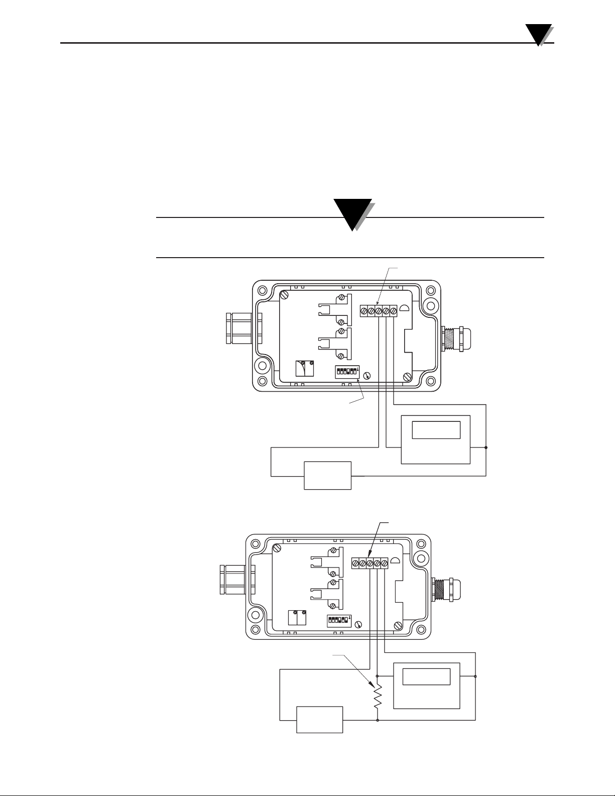
TB1 Terminal Block Connections
1. Calibration Signal Input (Square wave, 6.5 V TTL)
2. No Connection
3. + Power Supply
4. + mA/Vdc Output
5. – Power Supply
Transmitter Wiring Examples
During normal operation a shielded cable should be used, such as Omega’s TX4-100 cable. See figure
4 for proper earth ground wiring connections to the enclosure body.
Figure 7 - Current Output (4 to 20 mA)
Figure 8 - Voltage Output (1 to 5 Vdc)
FLSC90-A FIBER OPTIC FLOW TRANSMITTER
7
NOTE:
5
34
2
1
TB1
SW1
N
O
456
3
2
1
SWITCH "1" MUST BE "OFF"
FOR CURRENT OUTPUT
+
PSU-93
+
PWR
SUPPLY
SW1
N
26543
1
O
–
TB1
2
5
43
1
200 GPM
PROCESS METER
CURRENT INPUT
–
249 OHM SHUNT RESISTOR
PSU-93
+
PWR
SUPPLY
+
200 GPM
PROCESS METER
VOLTAGE INPUT
–
–
Page 12

Section 8 – Transmitter Scaling
Your transmitter has been factory tested to meet or exceed the specifications
outlined in this manual. The FLSC90-A must be scaled to operate for the correct
sensor and fitting size you will be using it with to maintain original
specifications. This procedure below is for scaling your transmitter. It is
generally recommended that your transmitter be re-scaled on an annual basis
depending on operating conditions and usage.
Recommended equipment for transmitter scaling.
Omega Model "PSU-93" DC Power Supply, Omega Model "HHM29" Handheld
Multi-Meter, Omega Model "CL123" Multi Purpose Calibrator/Simulator
Fitting/K-Factor Chart (Table A)
Model No. Pipe Size Flow Range (GPM) K-Factor
FP9005
1
⁄2" 1.0 - 20 938
FP9007
3
⁄4" 2.0 - 30 528
FP9010 1" 4.0 - 55 322
FP9012 1 1⁄4" 4.5 - 90 161
FP9015 1 1⁄2" 8.0 - 125 112
FP9020 2" 15 - 200 63.6
FP9025 2 1⁄2" 20 - 300 48.4
FP9030 3" 25 - 500 15.5
SW1 Settings (Table B)
Position ON OFF
1 Always Off
2 Run Mode Calibrate Mode
3 Not Used
4 251 – 520 Hz Range
5 65 – 129 Hz Range
6 130 – 260 Hz Range
FLSC90-A FIBER OPTIC FLOW TRANSMITTER
8
Page 13

Scaling Procedure:Calibration Frequencies
1. Calculate what your calibration frequencies you will be using in the procedure
and formulas below.
a. Find the K-Factor listed in figure Table A for the fitting you will be using, call
this "K"
b. Determine what your full scale flow rate will be in your application, call this
"MAX FLOW"
c. Using the formulas below calculate your "CAL MAX", "CAL LOW", "CAL
MID" and "CAL HIGH" frequencies.
CAL MAX = MAX FLOW x K
60
CAL LOW = CAL MAX x .25
CAL MID = CAL MAX x .50
CAL HIGH = CAL MAX x .75
2. Connect the FLSC90-A transmitter as shown in figure 9 (see next page) to the
power supply, multi-meter (set to measure milli-amps) and the frequency
simulator.
3. Apply power to the FLSC90-Atransmitter and allow the unit to warm-up for
10 min.
4. On SW1, (See figure 9), set switch #2 to the "OFF" position.
5. On SW1, using figure 9 as reference, set switch #4, 5 or 6 to the "ON" position
based on the "CAL MAX" frequency you calculated in "Step 1".
6. Turn the frequency calibrator to the "ON" position.
7. Set the frequency calibrator for a DC square wave (6.5 V In Amplitude)
output equal to the "CAL LOW" calculated in "Step 1".
8. On SW1, set switch #1 to the "ON" position.
9. Adjust the "ZERO" potentiometer (P1) until the ammeter reads 8.00 mA.
10. Set the frequency calibrator for an output equal to the "CAL HIGH"
frequency calculated in "Step 1".
11. Adjust the "SPAN" potentiometer (P2) until the ammeter reads 16.00 mA.
12. Set the frequency calibrator for an output equal to the "CAL MID" frequency
calculated in "Step 1", the output should read 12.00 mA±0.024.
13. Scaling complete.
FLSC90-A FIBER OPTIC FLOW TRANSMITTER
9
Page 14
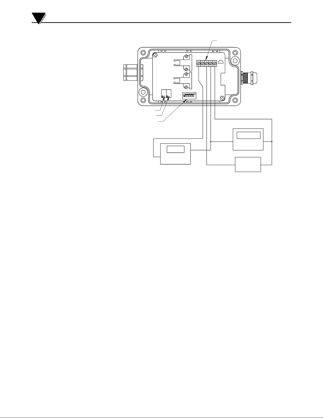
Figure 9 - Calibration Setup
Section 9 - Maintenance
Paddlewheel Sensor
Clean surfaces with warm soapy water, rinse well with clean cool water, air dry.
Signal Conditioner
No service or maintenance required.
FLSC90-A FIBER OPTIC FLOW TRANSMITTER
10
)
P1 (ZERO)
P2 (SPAN)
SW1 (DIP SWITCH)
SWITCH "2" MUST BE "OFF"
DURING CALIBRATION
200 Hz
+
FREQUENCY
SOURCE
(SET FOR 6.5V
SQUARE WAVE
TB1
5
2
1
43
SW1
N
O
54
321
6
12.00 mA
+
HHM29
MULTI-METER
–
–
+
PSU-93
PWR
SUPPLY
–
Page 15

Section 10 - Specifications
Accuracy (transmitter only): ±0.25% of full scale @ 22°C (72 ºF)
Repeatability: ±0.05% of full scale
Input: Light pulses from FP9001 flow sensor
Operating Temperature Range: 0 to 49°C (32 to 120°F)
Storage Temperature Range: -20 to 65°C (-4 to 149°F)
Output: User selectable, 4-20mA or 1-5 Vdc
Power: 12 –24 Vdc @ 40mA
Max Loop Resistance: Ohms = (V supply – 12V)/.02 A
Max Fiber Optic Cable Length 18ft. (clean clear liquids only)
Enclosure Housing: Painted Diecast Aluminum
Connections NEMA-4 rated,
Fiber Optic Sensor: Duplex Cable/Male Fiber Optic Connectors
Power/Output: Internal 6-Postion Terminal Strip for 14 to 22
gage wire.
Dimensions: See "Section 4 – Mounting"
Weight: 272 grams (.6 lbs.)
FLSC90-A FIBER OPTIC FLOW TRANSMITTER
11
Page 16

NOTES:
FLSC90-A FIBER OPTIC FLOW TRANSMITTER
12
Page 17

WARRANTY/DISCLAIMER
OMEGA ENGINEERING, INC. warrants this unit to be free of defects in materials and workmanship for a
period of 13 months from date of purchase. OMEGA’s WARRANTY adds an additional one (1) month
grace period to the normal one (1) year product warranty to cover handling and shipping time. This
ensures that OMEGA’s customers receive maximum coverage on each product.
If the unit malfunctions, it must be returned to the factory for evaluation. OMEGA’s Customer Service
Department will issue an Authorized Return (AR) number immediately upon phone or written request.
Upon examination by OMEGA, if the unit is found to be defective, it will be repaired or replaced at no
charge. OMEGA’s WARRANTY does not apply to defects resulting from any action of the purchaser,
including but not limited to mishandling, improper interfacing, operation outside of design limits,
improper repair, or unauthorized modification. This WARRANTY is VOID if the unit shows evidence of
having been tampered with or shows evidence of having been damaged as a result of excessive corrosion;
or current, heat, moisture or vibration; improper specification; misapplication; misuse or other operating
conditions outside of OMEGA’s control. Components which wear are not warranted, including but not
limited to contact points, fuses, and triacs.
OMEGA is pleased to offer suggestions on the use of its various products. However,
OMEGA neither assumes responsibility for any omissions or errors nor assumes liability for any
damages that result from the use of its products in accordance with information provided by
OMEGA, either verbal or written. OMEGA warrants only that the parts manufactured by it will be
as specified and free of defects. OMEGA MAKES NO OTHER WARRANTIES OR
REPRESENTATIONS OF ANY KIND WHATSOEVER, EXPRESS OR IMPLIED, EXCEPT THAT OF TITLE,
AND ALL IMPLIED WARRANTIES INCLUDING ANY WARRANTY OF MERCHANTABILITY AND
FITNESS FOR A PARTICULAR PURPOSE ARE HEREBY DISCLAIMED. LIMITATION OF
LIABILITY: The remedies of purchaser set forth herein are exclusive, and the total liability of
OMEGA with respect to this order, whether based on contract, warranty, negligence,
indemnification, strict liability or otherwise, shall not exceed the purchase price of the
component upon which liability is based. In no event shall OMEGA be liable for
consequential, incidental or special damages.
CONDITIONS: Equipment sold by OMEGA is not intended to be used, nor shall it be used: (1) as a “Basic
Component” under 10 CFR 21 (NRC), used in or with any nuclear installation or activity; or (2) in medical
applications or used on humans. Should any Product(s) be used in or with any nuclear installation or
activity, medical application, used on humans, or misused in any way, OMEGA assumes no responsibility
as set forth in our basic WARRANTY/ DISCLAIMER language, and, additionally, purchaser will indemnify
OMEGA and hold OMEGA harmless from any liability or damage whatsoever arising out of the use of the
Product(s) in such a manner.
RETURN REQUESTS/INQUIRIES
Direct all warranty and repair requests/inquiries to the OMEGA Customer Service Department. BEFORE
RETURNING ANY PRODUCT(S) TO OMEGA, PURCHASER MUST OBTAIN AN AUTHORIZED RETURN
(AR) NUMBER FROM OMEGA’S CUSTOMER SERVICE DEPARTMENT (IN ORDER TO AVOID
PROCESSING DELAYS). The assigned AR number should then be marked on the outside of the return
package and on any correspondence.
The purchaser is responsible for shipping charges, freight, insurance and proper packaging to prevent
breakage in transit.
FOR W
ARRANTY RETURNS, please have the
following information available BEFORE
contacting OMEGA:
1. Purchase Order number under which the product
was PURCHASED,
2. Model and serial number of the product under
warranty, and
3. Repair instructions and/or specific problems
relative to the product.
FOR NON-WARRANTY REPAIRS,
consult OMEGA
for current repair charges. Have the following
information available BEFORE contacting OMEGA:
1. Purchase Order number to cover the COST
of the repair,
2. Model and serial number of the product, and
3. Repair instructions and/or specific problems
relative to the product.
OMEGA’s policy is to make running changes, not model changes, whenever an improvement is possible. This affords
our customers the latest in technology and engineering.
OMEGA is a registered trademark of OMEGA ENGINEERING, INC.
© Copyright 2003 OMEGA ENGINEERING, INC. All rights reserved. This document may not be copied, photocopied,
reproduced, translated, or reduced to any electronic medium or machine-readable form, in whole or in part, without the
prior written consent of OMEGA ENGINEERING, INC.
Page 18

M4016/0702
Where Do I Find Everything I Need for
Process Measurement and Control?
OMEGA…Of Course!
Shop online at www.omega.com
TEMPERATURE
Thermocouple, RTD & Thermistor Probes, Connectors, Panels & Assemblies
Wire: Thermocouple, RTD & Thermistor
Calibrators & Ice Point References
Recorders, Controllers & Process Monitors
Infrared Pyrometers
PRESSURE, STRAIN AND FORCE
Transducers & Strain Gages
Load Cells & Pressure Gages
Displacement Transducers
Instrumentation & Accessories
FLOW/LEVEL
Rotameters, Gas Mass Flowmeters & Flow Computers
Air Velocity Indicators
Turbine/Paddlewheel Systems
Totalizers & Batch Controllers
pH/CONDUCTIVITY
pH Electrodes, Testers & Accessories
Benchtop/Laboratory Meters
Controllers, Calibrators, Simulators & Pumps
Industrial pH & Conductivity Equipment
DATA ACQUISITION
Data Acquisition & Engineering Software
Communications-Based Acquisition Systems
Plug-in Cards for Apple, IBM & Compatibles
Datalogging Systems
Recorders, Printers & Plotters
HEATERS
Heating Cable
Cartridge & Strip Heaters
Immersion & Band Heaters
Flexible Heaters
Laboratory Heaters
ENVIRONMENTAL
MONITORING AND CONTROL
Metering & Control Instrumentation
Refractometers
Pumps & Tubing
Air, Soil & Water Monitors
Industrial Water & Wastewater Treatment
pH, Conductivity & Dissolved Oxygen Instruments
 Loading...