

Page 1
www.omega.com
e-mail: [email protected]
omega.com
®
®
User’s Guide
Shop online at
FLSC-18B, FLSC-28,
FLSC-34, FLSC-35B,
FLSC-51/51B
Signal Conditioners
Page 2

Servicing North America:
USA: One Omega Drive, Box 4047
ISO 9001 Certified Stamford CT 06907-0047
Tel: (203) 359-1660 FAX: (203) 359-7700
e-mail: [email protected]
Canada: 976 Bergar
Laval (Quebec) H7L 5A1
Tel: (514) 856-6928 FAX: (514) 856-6886
e-mail: [email protected]
For immediate technical or application assistance:
USA and Canada: Sales Service: 1-800-826-6342 / 1-800-TC-OMEGA
®
Customer Service: 1-800-622-2378 / 1-800-622-BEST
®
Engineering Service: 1-800-872-9436 / 1-800-USA-WHEN
®
TELEX: 996404 EASYLINK: 62968934 CABLE: OMEGA
Mexico: En Espan˜ol: (001) 203-359-7803 e-mail: [email protected]
FAX: ( 001) 203-359-7807 [email protected]
Servicing Europe:
Benelux: Postbus 8034, 1180 LA Amstelveen, The Netherlands
Tel: +31 (0)20 3472121 FAX: +31 (0)20 6434643
Toll Free in Benelux: 0800 0993344
e-mail: [email protected]
Czech Republic: Rudé armády 1868, 733 01 Karviná 8
France: 9, rue Denis Papin, 78190 Trappes
Tel: +33 (0)130 621 400 FAX: +33 (0)130 699 120
Toll Free in France: 0800-4-06342
e-mail: [email protected]
Germany/Austria: Daimlerstrasse 26, D-75392 Deckenpfronn, Germany
Tel: +49 (0)7056 9398-0 FAX: +49 (0)7056 9398-29
Toll Free in Germany: 0800 639 7678
e-mail: [email protected]
United Kingdom: One Omega Drive, River Bend Technology Centre
ISO 9002 Certified Northbank, Irlam, Manchester
M44 5EX United Kingdom
Tel: +44 (0)161 777 6611 FAX: +44 (0)161 777 6622
Toll Free in United Kingdom: 0800-488-488
e-mail: [email protected]
omega.comomega.com
OMEGAnet®Online Service Internet e-mail
www.omega.com [email protected]
It is the policy of OMEGA to comply with all worldwide safety and EMC/EMI regulations that
apply. OMEGA is constantly pursuing certification of its products to the European New Approach
Directives. OMEGA will add the CE mark to every appropriate device upon certification.
The information contained in this document is believed to be correct, but OMEGA Engineering, Inc. accepts
no liability for any errors it contains, and reserves the right to alter specifications without notice.
WARNING: These products are not designed for use in, and should not be used for, patient-connected applications.
®
®
Page 3

WARRANTY/DISCLAIMER
OMEGA ENGINEERING, INC. warrants this unit to be free of defects in materials and
workmanship for a period of 13 months from date of purchase. OMEGA’s Warranty
adds an additional one (1) month grace period to the normal one (1) year product
warranty to cover handling and shipping time. This ensures that OMEGA’s
customers receive maximum coverage on each product.
If the unit malfunctions, it must be returned to the factory for evaluation. OMEGA’s
Customer Service Department will issue an Authorized Return (AR) number immediately upon phone or written request. Upon examination by OMEGA, if the unit is found to
be defective, it will be repaired or replaced at no charge. OMEGA’s WARRANTY does
not apply to defects resulting from any action of the purchaser, including but not limited to mishandling, improper interfacing, operation outside of design limits, improper
repair, or unauthorized modification. This WARRANTY is VOID if the unit shows evidence of having been tampered with or shows evidence of having been damaged as a
result of excessive corrosion; or current, heat, moisture or vibration; improper specification; misapplication; misuse or other operating conditions outside of OMEGA’s control. Components which wear are not warranted, including but not limited to contact
points, fuses, and triacs.
OMEGA is pleased to offer suggestions on the use of its various products.
However, OMEGA neither assumes responsibility for any omissions or errors nor
assumes liability for any damages that result from the use of its products in
accordance with information provided by OMEGA, either verbal or written.
OMEGA warrants only that the parts manufactured by it will be as specified and
free of defects. OMEGA MAKES NO OTHER WARRANTIES OR REPRESENTATIONS OF ANY KIND WHATSOEVER, EXPRESS OR IMPLIED, EXCEPT THAT OF
TITLE, AND ALL IMPLIED WARRANTIES INCLUDING ANY WARRANTY OF MERCHANTABILITY AND FITNESS FOR A PARTICULAR PURPOSE ARE HEREBY DISCLAIMED. LIMITATION OF LIABILITY: The remedies of purchaser set forth herein
are exclusive, and the total liability of OMEGA with respect to this order, whether
based on contract, warranty, negligence, indemnification, strict liability or otherwise, shall not exceed the purchase price of the component upon which liability
is based. In no event shall OMEGA be liable for consequential, incidental or special damages.
CONDITIONS: Equipment sold by OMEGA is not intended to be used, nor shall it be
used: (1) as a “Basic Component” under 10 CFR 21 (NRC), used in or with any nuclear
installation or activity; or (2) in medical applications or used on humans. Should any
Product(s) be used in or with any nuclear installation or activity, medical application,
used on humans, or misused in any way, OMEGA assumes no responsibility as set
forth in our basic WARRANTY/DISCLAIMER language, and, additionally, purchaser will
indemnify OMEGA and hold OMEGA harmless from any liability or damage
whatsoever arising out of the use of the Product(s) in such a manner.
RETURN REQUESTS/INQUIRIES
Direct all warranty and repair requests/inquiries to the OMEGA Customer Service
Department. BEFORE RETURNING ANY PRODUCT(S) TO OMEGA, PURCHASER
MUST OBTAIN AN AUTHORIZED RETURN (AR) NUMBER FROM OMEGA’S
CUSTOMER SERVICE DEPARTMENT (IN ORDER TO AVOID PROCESSING DELAYS).
The assigned AR number should then be marked on the outside of the return package
and on any correspondence.
The purchaser is responsible for shipping charges, freight, insurance and proper
packaging to prevent breakage in transit.
FOR WARRANTY
RETURNS, please have
the following information available
BEFORE contacting OMEGA:
1. Purchase Order number under which
the product was PURCHASED,
2. Model and serial number of the product
under warranty, and
3. Repair instructions and/or specific
problems relative to the product.
FOR NON-WARRANTY REPAIRS,
consult
OMEGA for current repair charges. Have
the following information available
BEFORE contacting OMEGA:
1. Purchase Order number to cover the
COST of the repair,
2. Model and serial number of the product,
and
3. Repair instructions and/or specific
problems relative to the product.
OMEGA’s policy is to make running changes, not model changes, whenever an improvement is possible.
This affords our customers the latest in technology and engineering.
OMEGA is a registered trademark of OMEGA ENGINEERING, INC.
© Copyright 2001 OMEGA ENGINEERING, INC. All rights reserved. This document may not be copied,
photocopied, reproduced, translated, or reduced to any electronic medium or machine-readable form, in
whole or in part, without the prior written consent of OMEGA ENGINEERING, INC.
Page 4
i
GENERAL TABLE OF CONTENTS
MODEL NO. PAGE
FLSC-18B ...................................................................................... 3
FLSC-28 .................................................................................... 15
FLSC-34 .................................................................................... 28
FLSC-35B .................................................................................... 41
FLSC-51/51B .............................................................................. 54
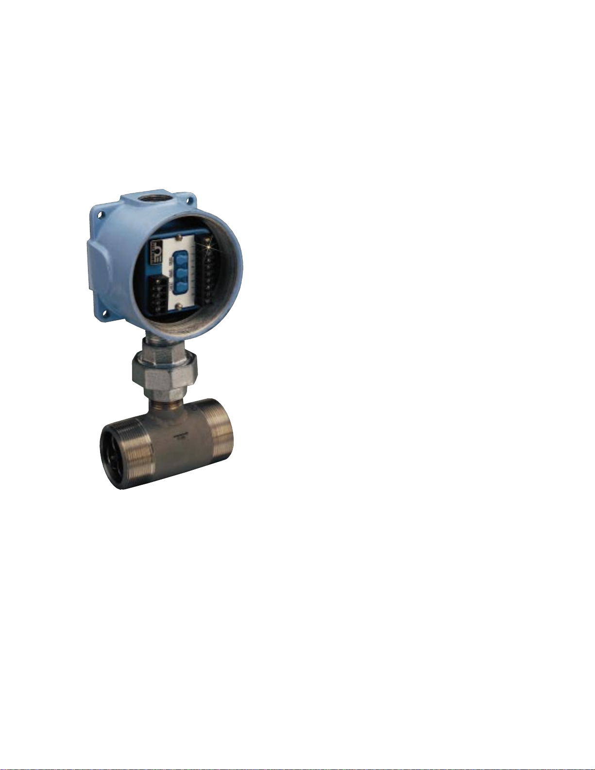
FLSC-35B With Explosion-Proof Housing
Mounted on FTB 100 Turbine Meter
Page 5

ii
NOTES:
Page 6

1
GENERAL CONSIDERATIONS
FLOWMETER INSTALLATION
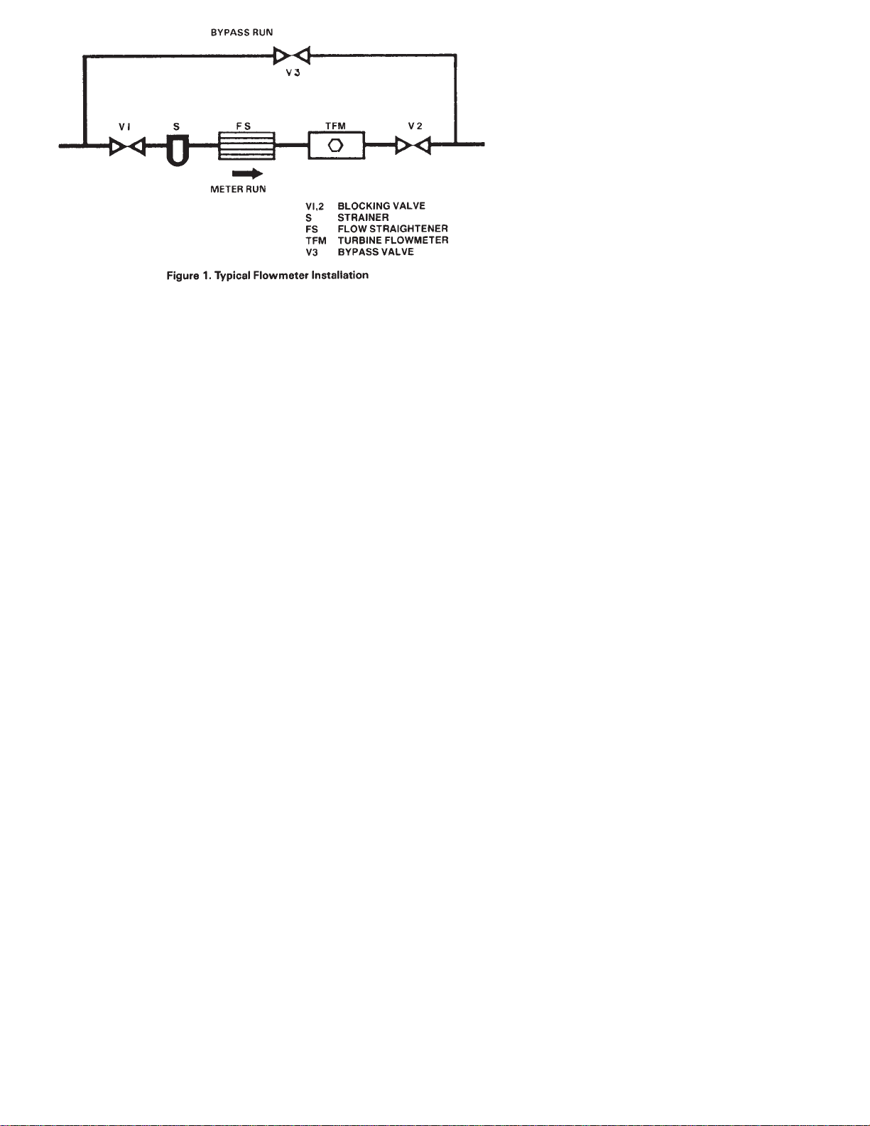
Proper application of the turbine flowmeter requires a suitable
piping installation in order to achieve accurate and reliable
operation. (Refer to Figure 1).
The piping configuration immediately preceding and following
the flowmeter is termed the meter run. Refer to the flowmeter's
operators manual when installing the flowmeter and meter run.
RELATIVE - The performance of the turbine flowmeter is
affected by fluid swirl and non-uniform velocity profiles. The
following recommendation will reduce such flow irregularities.
It is advisable not to locate the meter run immediately
downstream of pumps, partially opened valves, bends or other
similar piping configurations. In addition, the area surrounding
the flowmeter should be free of sources of electrical noise such
as motors, solenoids, transformers and power lines which may
be coupled to the pickoff device.
The metering section should not be subjected to excessive
vibration or shock. Such a condition may result in a
mechanically induced output signal from the pickoff device.
METER RUN - In general, the meter run should be chosen to
have the same inner diameter as the meter bore. A minimum of
10 pipe diameters of straight pipe up stream and 5 pipe
diameters downstream are required. Where this optimum line
configuration can not be implemented, it is advisable to install a
flow straightener properly positioned upstream of the f
lowmeter. Orientation is not a critical factor, however,
horizontal is a preferred orientation.
BYPASS RUN - A properly sized bypass run with suitable
blocking valves may be equipped where an interruption in fluid
flow for turbine meters servicing can not be tolerated.
STRAINER - A strainer, filter and/or air eliminator is
recommended to reduce the potential of fouling or damage.
On initial startup of a line, it is advisable to install a spool piece
purging the line to eliminate damaging the flowmeter, due to
flux, tape, solder, welds or other contaminates carried along by
the fluid stream.
CAVITATION - Cavitation causes measurement inaccuracies in
turbine flowmeters and should be avoided by suitable line and
operating configurations.
Figure 1. Typical Flowmeter Installation
Page 7
2
Whenever the pressure within a pipeline instantaneously falls
below. the equilibrium vapor pressure of the fluid, a portion of
the fluid, vaporizes and forms bubbles i n the pipeline. This is
termed cavitation. Cavitation is eliminated by maintaining
adequate back pressure on the flowmeter. A downstream valve
that provides the necessary back pressure is one means for
preventing cavitation in the metering run. Control valves should
be located downstream, if possible. Some installations may also
make use of a vapor eliminator upstream of the flowmeter.
The minimum required back pressure may be estimated using
the following equation:
Min. Back Pressure = 1.3 X Vapor Pressure + 2X Pressure Drop
INSTALLATION WIRING LAYOUT FOR INTERCONNECTIONS
In considering the interconnections between the flowmeter and
the flow measurement system some attention must be given to
anticipated noise sources and to the coupling of these noise
sources to the interconnecting wiring.
Noise signals may be coupled inductively or capacitively into
the wiring between the flowmeter and the electronic measuring
systems. In general, utilizing a shielded, twisted pair for the
interconnection greatly reduces this coupling. The shield should
be grounded on one end of the cable only. In general, grounding
only on the electronic measuring system is best.
However, even with proper interconnecting cabling, cross talk
with other signal lines or power lines may still occur and should
be avoided. Physical isolation in the manner in which the wiring
is run reduces the chance of potential problems.
Page 8

3
TABLE OF CONTENTS
FLSC-18B SIGNAL CONDITIONER
SECTION PAGE
SECTION 1 INTRODUCTION ........................................... 4
SECTION 2 INSTALLATION . ............................................ 4
2.1 Unpacking ............................................................................. 4
2.2 Installation of the FLSC-18B ............................................... 4
SECTION 3 OPERATION .................................................... 7
3.1 Principle of Operation ......................................................... 7
3.2 Controls and Adjustments ................................................. 7
SECTION 4 CALIBRATION OF ANALOG OUTPUT ... 10
4.1 Introduction ........................................................................ 10
4.2 Procedure ............................................................................ 10
SECTION 5 TROUBLESHOOTING ................................ 12
SECTION 6 SPECIFICATIONS ........................................ 13
Page 9

4
SECTION 1 INTRODUCTION
The OMEGA®FLSC-18B High Accuracy Integral Signal
Conditioner is designed for direct mounting onto OMEGA
Series FTB-100 and 200 Turbine Meters.
The input circuitry of the signal conditioners has been designed
to receive and condition the low level turbine meter signals
while rejecting unwanted noise and spurious signals. A signal
threshold control is provided which allows the user to set the
input sensitivity above the ambient noise level, thereby
eliminating any false signal on the output.
The output signal is a DC current (4-20 mA) which is
proportional to flow rate. The FLSC-18B is powered by a user
supplied, filtered DC voltage. An on board regulator provides
the required regulation and noise rejection.
A zero and span potentiometer allow for simple field
adjustment of the analog output from the signal conditioner.
SECTION 2 INSTALLATION
2.1 UNPACKING
Remove the Packing List and verify that all equipment has been
received. If there are any questions about the shipment, please
call OMEGA Customer Service Department.
Upon receipt of shipment, inspect the container and equipment
for any signs of damage. Take particular note of any evidence of
rough handling in transit. Immediately report any damage to
the shipping agent.
The carrier will not honor any claims unless all shipping material is saved
for their examination. After examining and removing contents, save
packing material and carton in the event reshipment is necessary.
2.2 INSTALLATION OF THE FLSC-18B
The FLSC-18B should be placed in a convenient location which
maintains access to the unit should repairs or readjustment be
required.
If the unit is mounted on a turbine flowmeter in an explosion
proof conduit enclosure, orientate the flowmeter and run
conduit to prevent the accumulation of moisture in the conduit
enclosure as much as is practical. In addition, assure electronics
will not be overheated by hot process lines.
NOTE
Page 10
5
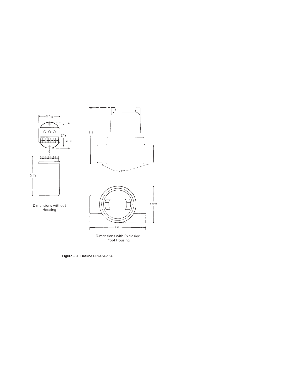
Refer to Figure 2-1 for outline dimensions. Drill appropriate
mounting holes as required.
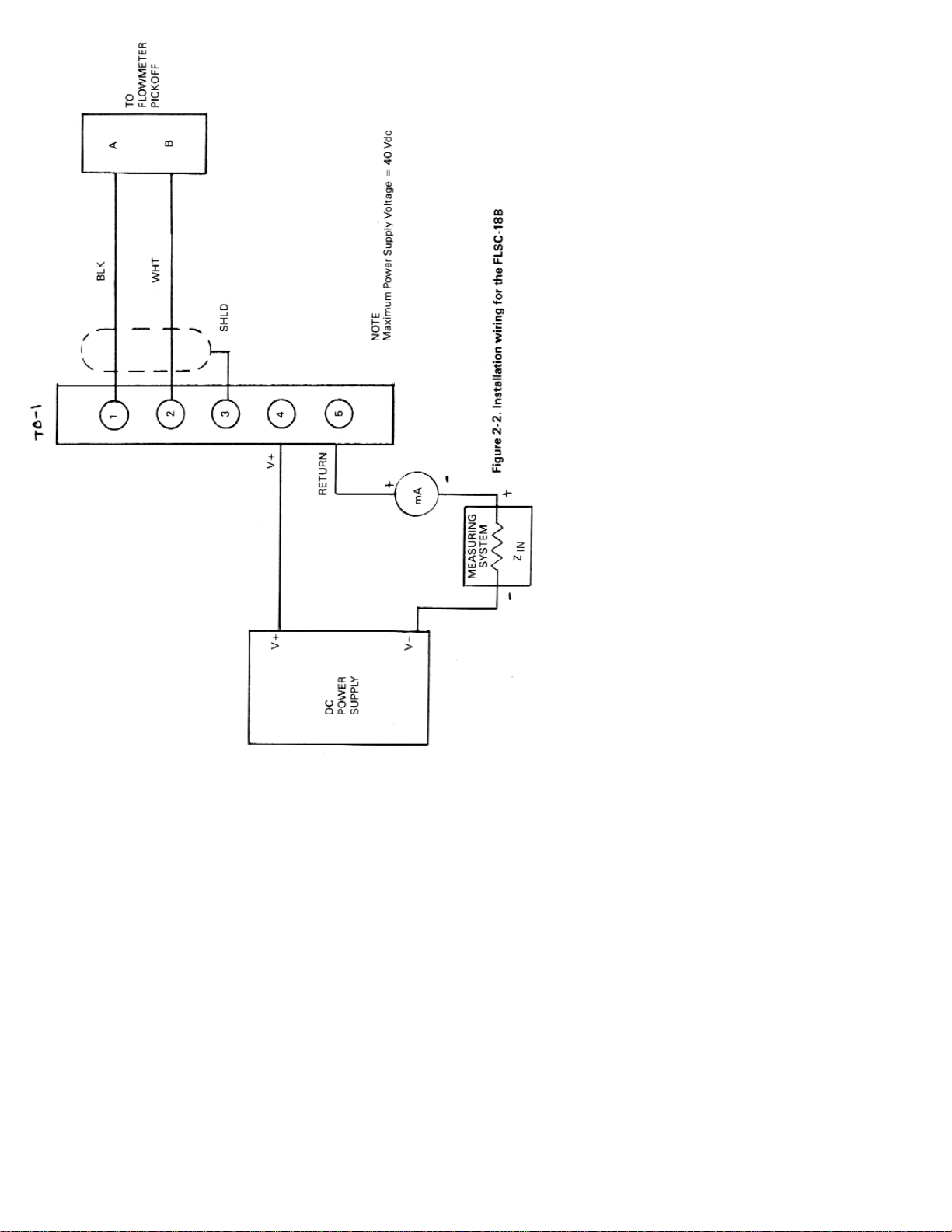
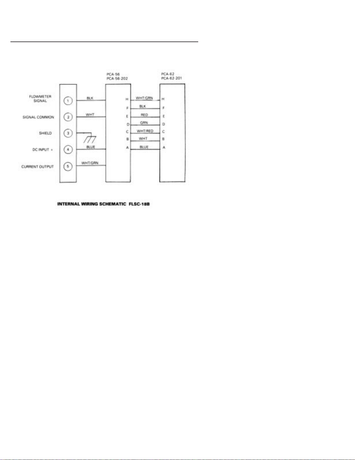
Refer to Figure 2-2, wiring installation drawing for appropriate
terminals for interconnections. The signal leads from the turbine
should be shielded whenever the FLSC-18B is not integrally
mounted. Ground shield on one end only. If desired,use solder
lug provided on ground stud. Connections to the terminal block
should be carefully dressed to avoid having bare wires
extending pass the screw clamp on the terminal block. This is
particularly important or units mounted within the explosion
proof enclosure. Wires should be neatly dressed near bottom of
enclosure to assure wiring will not become fouled when cover is
installed.
Connect two conductor shielded cable from flowmeter. Connect
shield to FLSC-18B only.
Unit is powered by a DC voltage which must be within 8 to 40
volts. Connect power as outlined in Figure 2-2.
Page 11
6
Page 12

7
SECTION 3 OPERATION
Perform any purging of piping with spool piece in place, Once
completed, install the flowmeter and connect cabling to pickup
coil and power to the unit. If false indication occurs turn
SENSITIVITY control counter clockwise until indication stops.
3.1 PRINCIPLE OF OPERATION
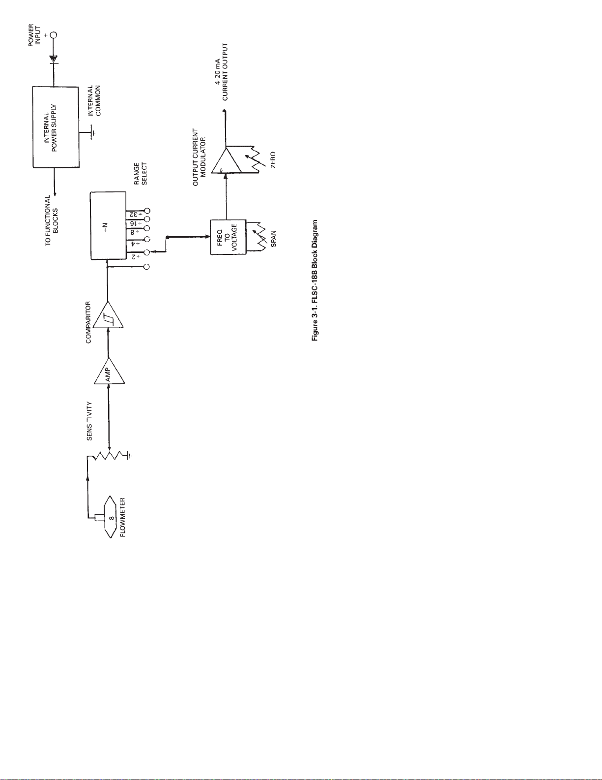
A simplified block diagram of the FLSC-18B Frequency to
Current Converter is shown in Figure 3-1. Key functional blocks
as well as flow information are designated. The basic operation
of the system is as follows.
The frequency signal from the flowmeter is connected to the
FLSC-18B with a twisted shielded pair cable. The signal enters
the SENSITIVITY control which is used to reject unwanted noise
by raising the trigger threshold above the background noise
present.
The low level flowmeter signal is then passed through a signal
conditioning chain where it is filtered, amplified and shaped
into a train of digital pulses whose frequency is related to the
volume flow rate and where each pulse represents a discrete
volume of fluid.
The signal entering the frequency to voltage converter is passed
through a combination of a divide by N and DIP switch matrix.
The ON output is chosen whose pulse rate is between 75 and
150 Hz at the maximum flow rate measured. This scaled pulse
rate is then filtered into an analog voltage. This voltage is
proportional to volumetric flow rate.
The resulting output voltage related to flow is then fed into the
output amplifier. The output amplifier is a voltage to current
amplifier and offers ZERO and SPAN adjustments in the
process range of 4-20 mA.
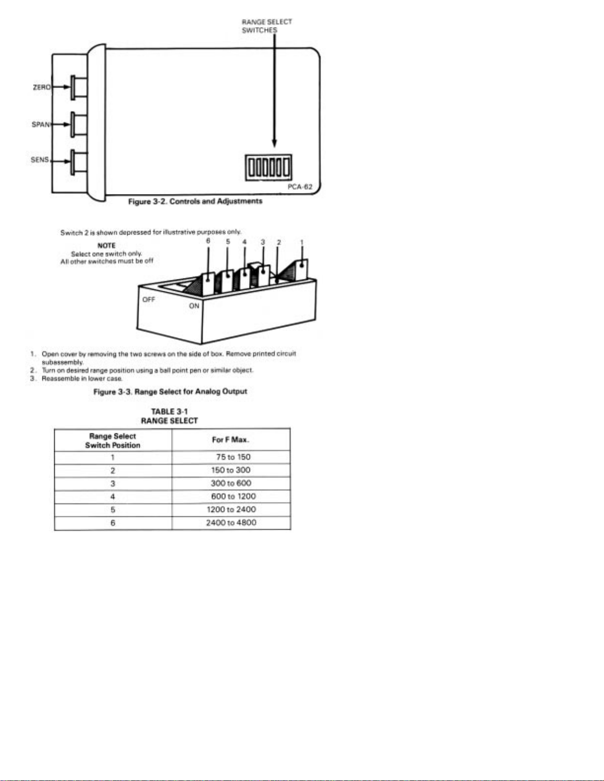
3.2 CONTROLS AND ADJUSTMENTS (See Figure 3-2.)
SENS A single turn control used to set the threshold
sensitivity level above the ambient noise pickup.
RANGE A dual in line (DIP) switch (see Figure 3-3 and Table 3-
1.) located within the enclosure which is used to
program the module to accept an input frequency range.
SPAN A multiple turn adjustment which is used to set the
voltage output signal to the desired span
corresponding to the equivalent flow range li.e., 4 to
20mA corresponding to 0-100 GPM).
ZERO A multiple turn adjustment which is used to set output
signal with no flow to the desired “zero” value (ie., 4 mA).
Page 13
8910
Page 14
Page 15

SECTION 4 CALIBRATION OF ANALOG OUTPUT
4.1 INTRODUCTION
In general, all flow measurement systems supplied by OMEGA
Engineering have been factory calibrated as specified by the
user, at the time of purchase.
Field calibration is only required when a change has occurred or
is sought to the measuring system. Such a change may be due to
repair, replacement or recalibration of the flowmeter, or perhaps
a change in the analog output span.
4.2 PROCEDURE
Begin by determining the equivalent maximum volumetric flow
rate in GPM, expected by the application, term this GPM
(MAX). GPM (MAX) may be calculated based on the analog
output scale requirements or may,be the maximum flow rate
listed on the flowmeter’s calibration sheet.
From the calibration constant (or K Factor) listed on the data
sheet for the flowmeter, obtain the frequency corresponding to
GPM (MAX) using Equation #1 and designate this frequency F
(MAX).
Equation #1 F
MAX = KAVE X
GPM
MAX
60
The analog output of the FLSC-18B may be calibrated with the
aid of an external oscillator used in conjunction with a
frequency counter.
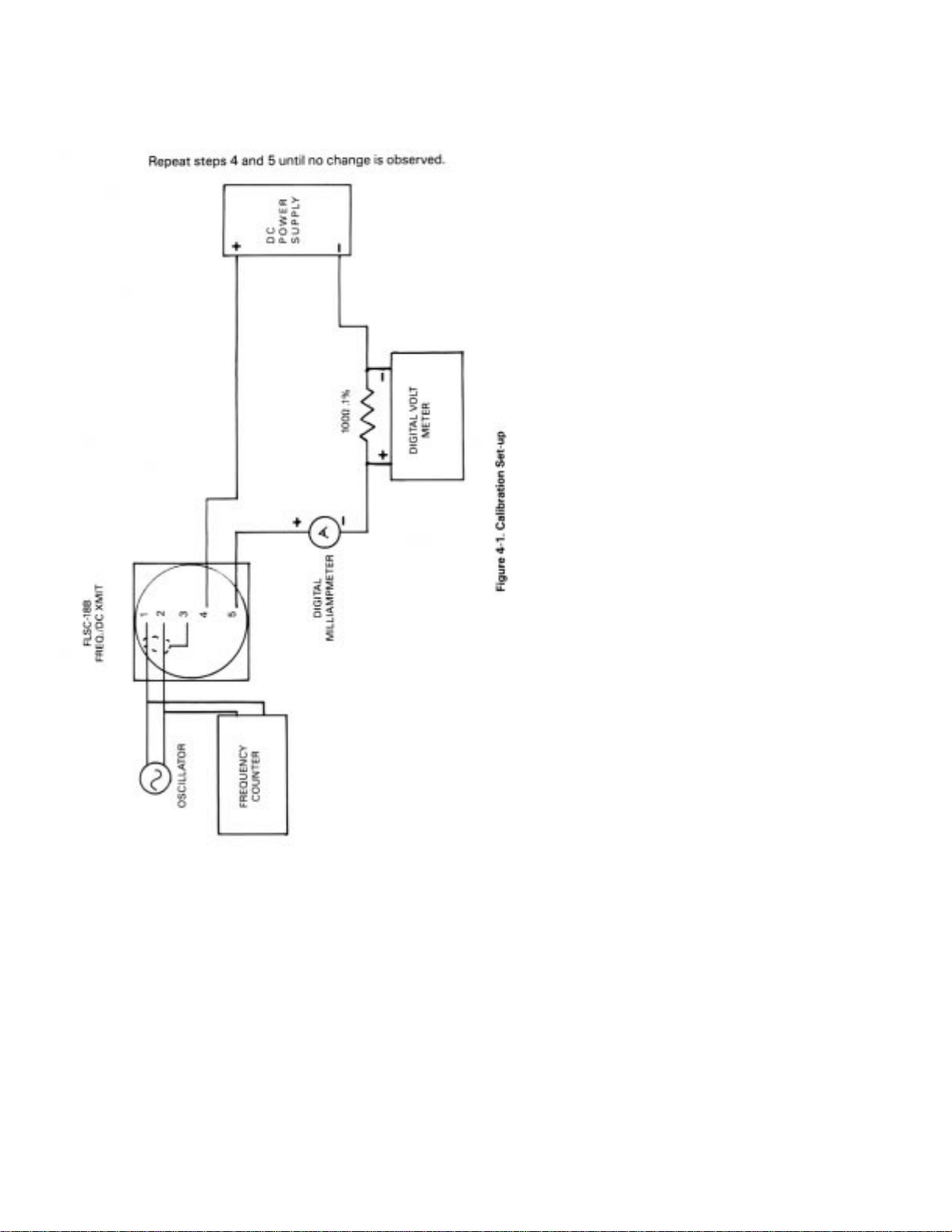
The external oscillator is used to supply a test frequency. In this
method, the external oscillator is connected to the signal input
terminals as shown in Figure 4-1. The oscillator’s output
frequency is set to equal F (MAX) as indicated on the frequency
counter.
1. The course range adjustment is accomplished by selecting a
switch position on a DIP switch located on the PCA62 printed
circuit card. See Table 3-1 to determine required switch
position and set into switch as shown in Figure 3-2. for
anticipated F MAX.
It is necessary to open the cover of the enclosure by removing two screws
on side of box and lifting cover. Two printed circuit cards are attached. The
“RANGE” Dip Switch may be programmed with a pen. Input power should
be removed during this step.
2.. Connect a digital milliampmeter or digital voltmeter as
shown in Figure 4-1.
NOTE
Page 16
11
3. Adjust SPAN control fully counter clockwise or 20 turns,
4. Adjust ZERO control for desired zero current (i.e., 4 mA).
5. Inject the Test Frequeney equal to F MAX while adjusting
SPAN for current equal to desired Full Scale (20 mA). See test
setup shown in Figure 4-1.)
Page 17

12
SECTION 5 TROUBLESHOOTING
In case of an inoperable or malfunctioning system the following
procedures can be used to isolate the faulty wiring, printed
circuit boards and/or alternate causes. The majority of repairs
can be made in the field thereby reducing the time a unit is out
of service.
The necessary documentation is contained within this manual with
the exception of the calibration data sheet for the turbine
flowmeter. This calibration is supplied with the turbine flowmeter.
Factory consultation is available to assist in diagnosing
problems. Please note that in some cases factory repairs can be
performed more easily than can be accomplished in the field.
Failure conditions are listed and the possible corrective actions
given to eliminate the observed problem.
Proper operation of the FLSC-18B can be assurned when with
power applied to the unit, the analog output produces a current
output signal of 4-20 mA with a span corresponding to that
established by the calibration procedure.
OBSERVED CONDITION CORRECTIVE ACTION
A. Analog Output 1. Noise on input. Slowly turn
With No Flow SENS pot CCW until false
indication stops.
NOTE: In fully CCW position
the unit will not operate.
2. Replace pickup coil
3. Defective FLSC-186, repair or
replace,
B. Incorrect Zero Reading 1. Verify that power supply
With No Flow voltage is sufficient for the
required load resistance,
2. Unit is out of calibration - re
calibrate.
3. Defective FLSC-18B, repair or
replace.
C. Current Exceeds 1 . Flowmeter being used beyond
Desired Span calibrated span of FLSC-18B
2. Calibration of FLSC-18B in
correct. Recalibrate.
3. Defective unit, repair or re
place.
Page 18
13
D. No Current Output 1. Power supply polarity is re
at All versed. Check wiring as per
wiring installation.
2. Short on flowmeter coil or
shield. Replace coil and
check wiring.
3. Defective unit, repair or
replace.
SECTION 6 SPECIFICATIONS
INPUT: Input protected, RF and band pass filtered adjustable
trigger level.
Input Impedance 40 kilohm (nominal)
Trigger Sensitivity 10 millivolt RMS (minimum) 10 to 1000 Hz
Over Voltage 120 volts RMS absolute (maximum)
CURRENT OUTPUT: Accuracy ±0.05% of full scale +200 PPM/°C
Range 4-20 mA
Response time 0.5 seconds for 10 to 90%
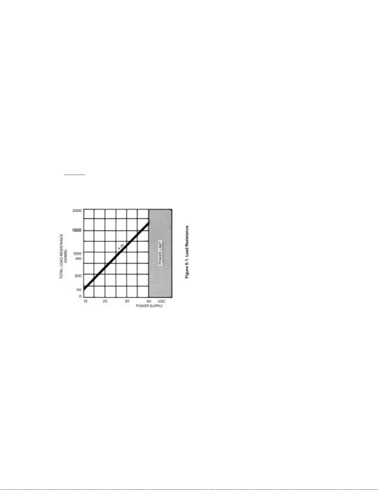
Load Resistance: Dependent on excitation voltage (see Figure 5-1)
RLOAD = VExt
-8
I.F.S.
where VExt = Excitation Voltage
I.F.S. = Full Scale Current
Output ripple less than 0.2% of F.S.
INPUT POWER: 8-40 VdC @ 30 mA
TEMPERATURE RANGE: 0°- 70°C (32° to 158°F)
ELECTRICAL CONNECTIONS: Screw Terminals
MAXIMUM LEAD LENGTH: 100 ft. of 24 gage copper wire
Page 19
14
SECTION 6 SPECIFICATIONS (CONT.)
ELECTRICAL HOUSING: Class I, Group D
Class 11 Group E, F, G
Class III
Page 20

15
TABLE OF CONTENTS
FLSC-28 SIGNAL CONDITIONER
SECTION PAGE
SECTION 1 INTRODUCTION ......................................... 16
SECTION 2 INSTALLATION ........................................... 16
2.1 Unpacking ........................................................................... 16
2.2 Installation of the FLSC-28 ............................................... 16
SECTION 3 OPERATION .................................................. 19
3.1 Principle of Operation ....................................................... 19
3.2 Controls and Adjustments ............................................... 21
SECTION 4 CALIBRATION OF ANALOG OUTPUT ... 22
4.1 Introduction ........................................................................ 22
4.2 Calibration Procedure ....................................................... 22
SECTION 5 TROUBLESHOOTING ................................ 25
SECTION 6 SPECIFICATIONS ........................................ 26
Page 21

16
SECTION 1 INTRODUCTION
The OMEGA®FLSC-28 High Accuracy Integral Signal
Conditioners are designed for direct mounting onto OMEGA
Series FTB-100 and 200 Turbine Meters.
The input circuitry of the FLSC-28 Signal Conditioners has been
designed to receive and condition the low level turbine meter
signals while rejecting unwanted noise and spurious signals. A
signal threshold control is provided which allows the user to set
the input sensitivity above the ambient noise level, thereby
eliminating any false signal on the output.
The FLSC-28 provides a 0-5 V output that runs off user supplied
10-40Vdc power supply. A RESPONSE TIME control provides
for adjustment of the response time and output ripple to suit
user requirements. Non-interacting ZERO and SPAN controls
allow for convenient calibration of desired analog span. These
features combine to form an interface between a flow transducer
and a host system.
SECTION 2 INSTALLATION
2.1 UNPACKING
Remove the Packing List and verify that all equipment has been
received. If there are any questions about the shipment, please
call OMEGA Customer Service Department.
Upon receipt of shipment, inspect the container and equipment
for any signs of damage Take particular note of any evidence of
rough handling in transit. Immediately report any damage to
the shipping agent.
The carrier will not honor any claims unless all shipping material is saved
for their examination. After examining and removing contents, save
packing material and carton in the event reshipment is necessary.
2.2 INSTALLATION OF THE FLSC-28
The FLSC-28 should be placed in a convenient location which
maintains access to the unit should repairs or readjustment be
required.
If the unit is mounted on a turbine flowmeter in an explosion
proof conduit enclosure, orientate the f lowmeter and run
conduit to prevent the accumulation of moisture in the conduit
enclosure as much as is practical. In addition, assure electronics
will not be overheated by hot process lines.
NOTE
Page 22
17
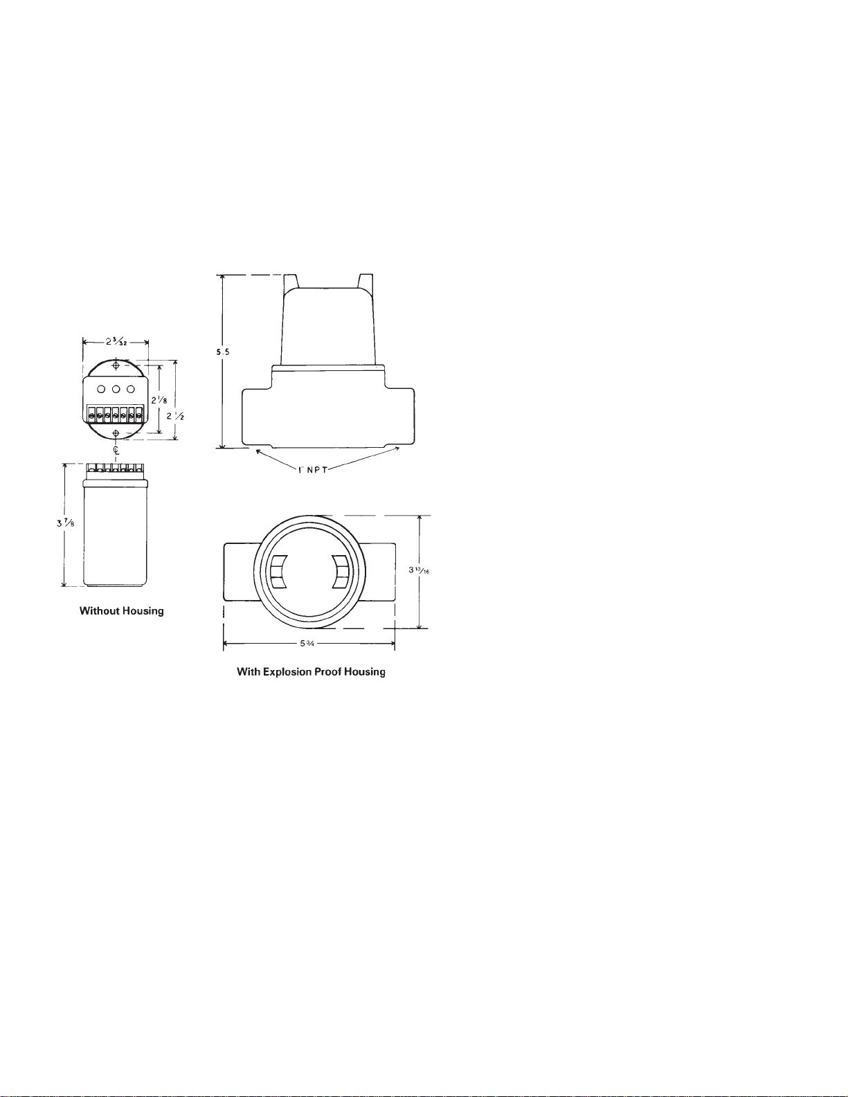
Refer to Figure 2-1, outline and installation drawings. Drill
mounting holes where appropriate.
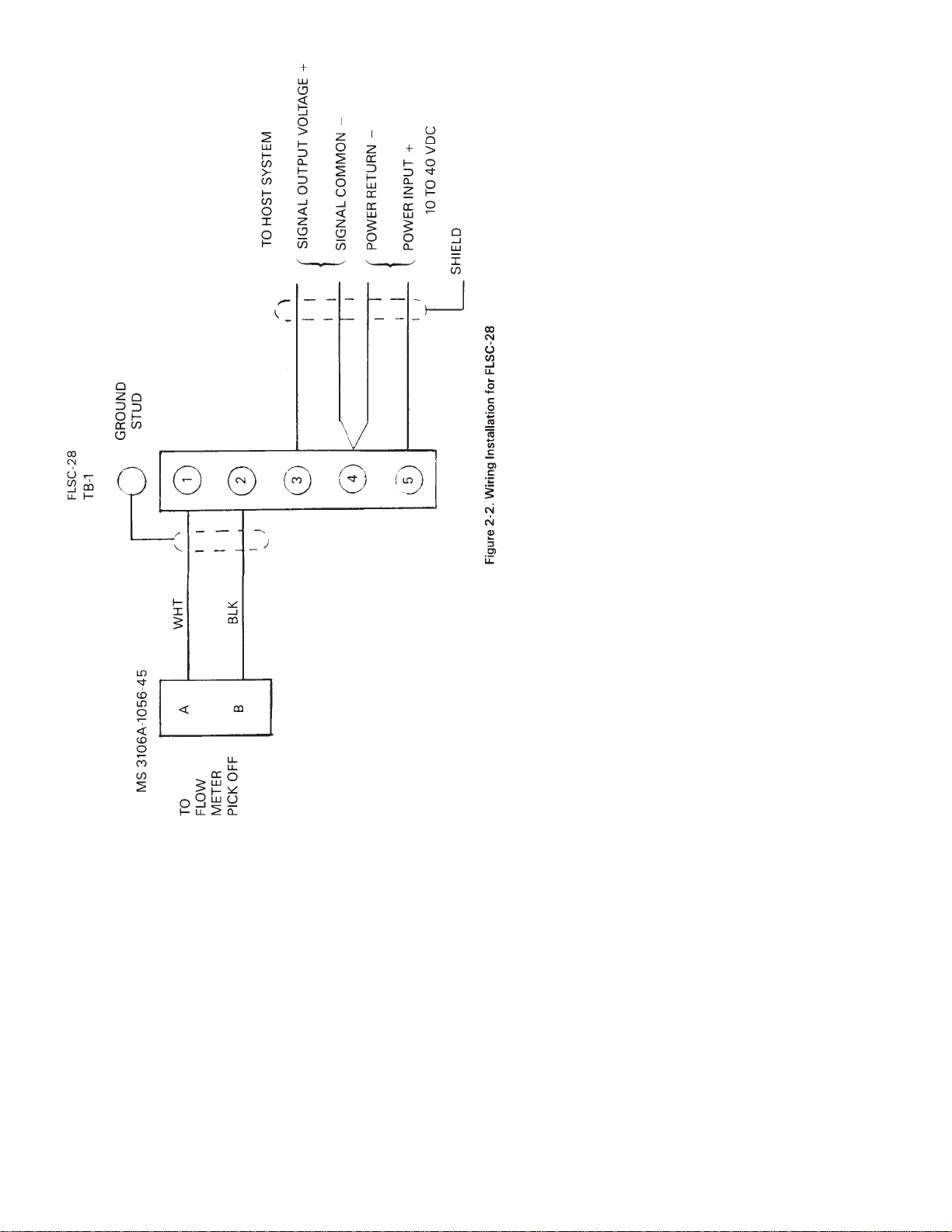
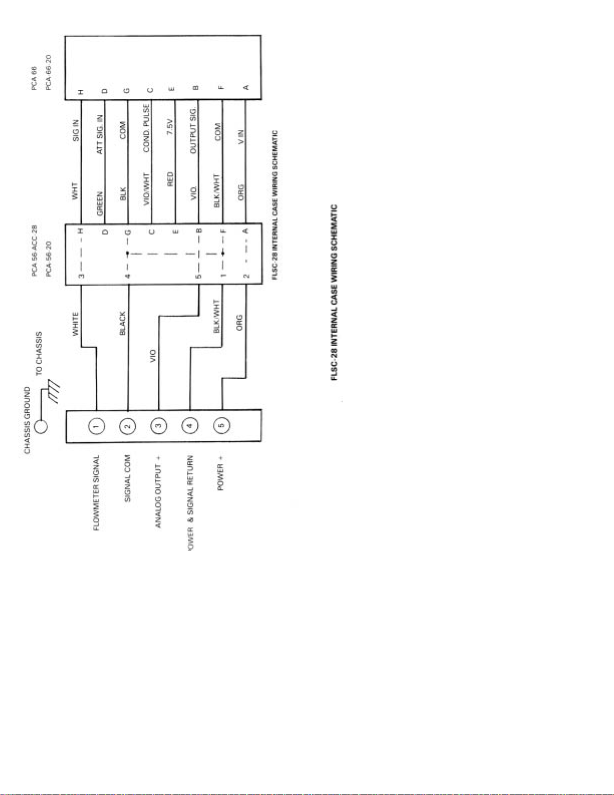
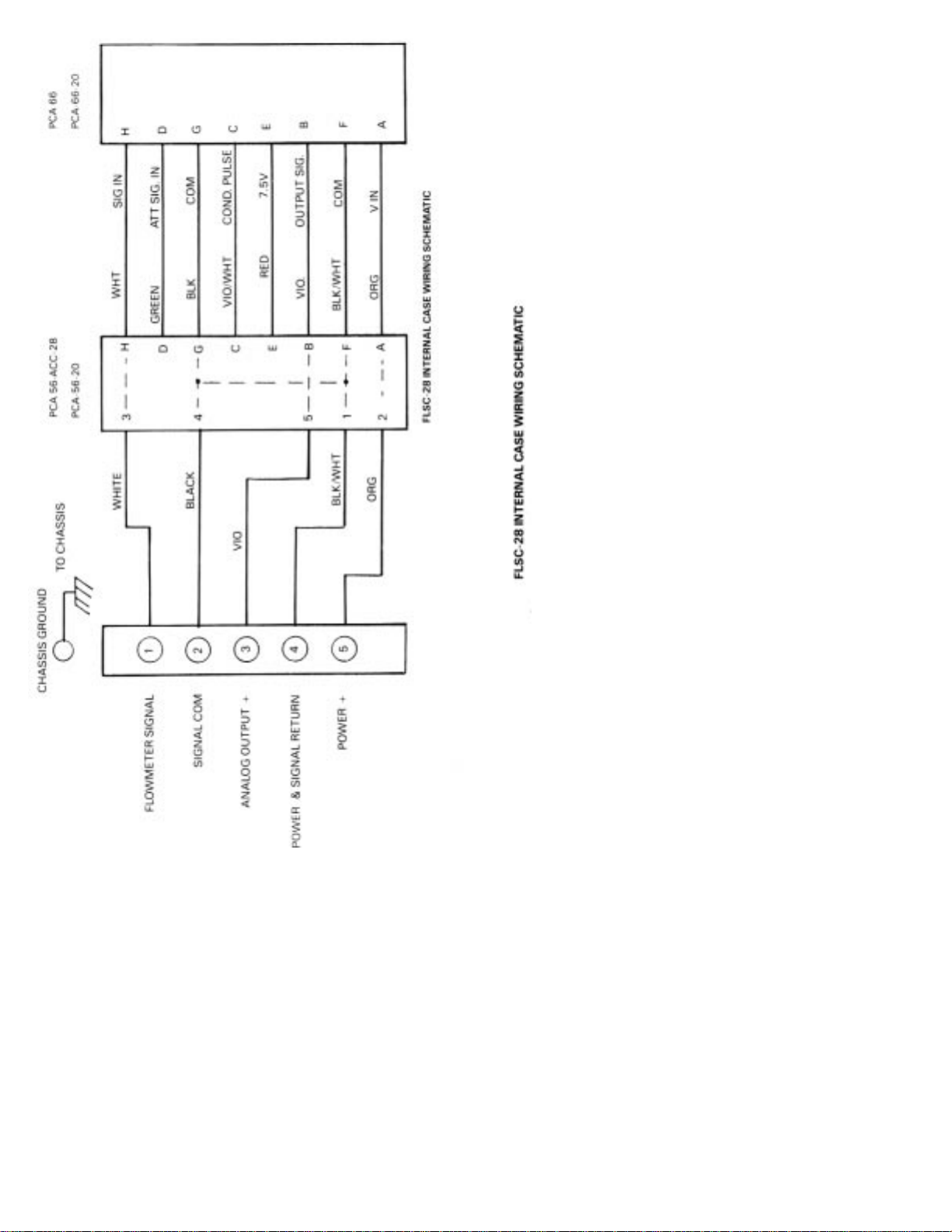
Refer to Figure 2-2, wiring the FLSC-28 for the appropriate
terminals for interconnections.
The signal leads f rom the turbine should be shielded whenever
the FLSC-28 is not integrally mounted. Ground shield on one
end only If desired, use solder lug provided on ground stud.
Connections to the terminal block should be carefully dressed to
avoid having bare wires extending pass the screw clamp on the
terminal block. This is particularly important for units mounted
within the explosion proof enclosure. Wires should be neatly
dressed near bottom of enclosure to assure wiring will not
become fouled when cover is installed.
Figure 2-1. Intallation Dimensions
Page 23
18
Page 24

19
The analog output signal leads may be run to the host system’s
signal input and power with the following options:
1. Four conductor shielded cable
2. Three conductor shielded cable (over short distances)
3. Two, two conductor shielded cables, one pair for signal
output, one pair for power input.
Ground shield at one end of cable only.
The power f or the FLSC-28 is provided by the Host System. 10-
40 Vdc should be provided and installed with correct polarity.
SECTION 3 OPERATION
Perform any purging of piping with spool piece in place. Once
completed, install the flowmeter and connect cabling to pickup
coil and power to the unit. If false indication occurs turn
SENSITIVITY control counterclockwise until indication stops.
The analog output commences with flow through the flowmeter.
For the analog output, the span is established by either the
factory calibration or field calibration. The range is 0-5 Vdc.
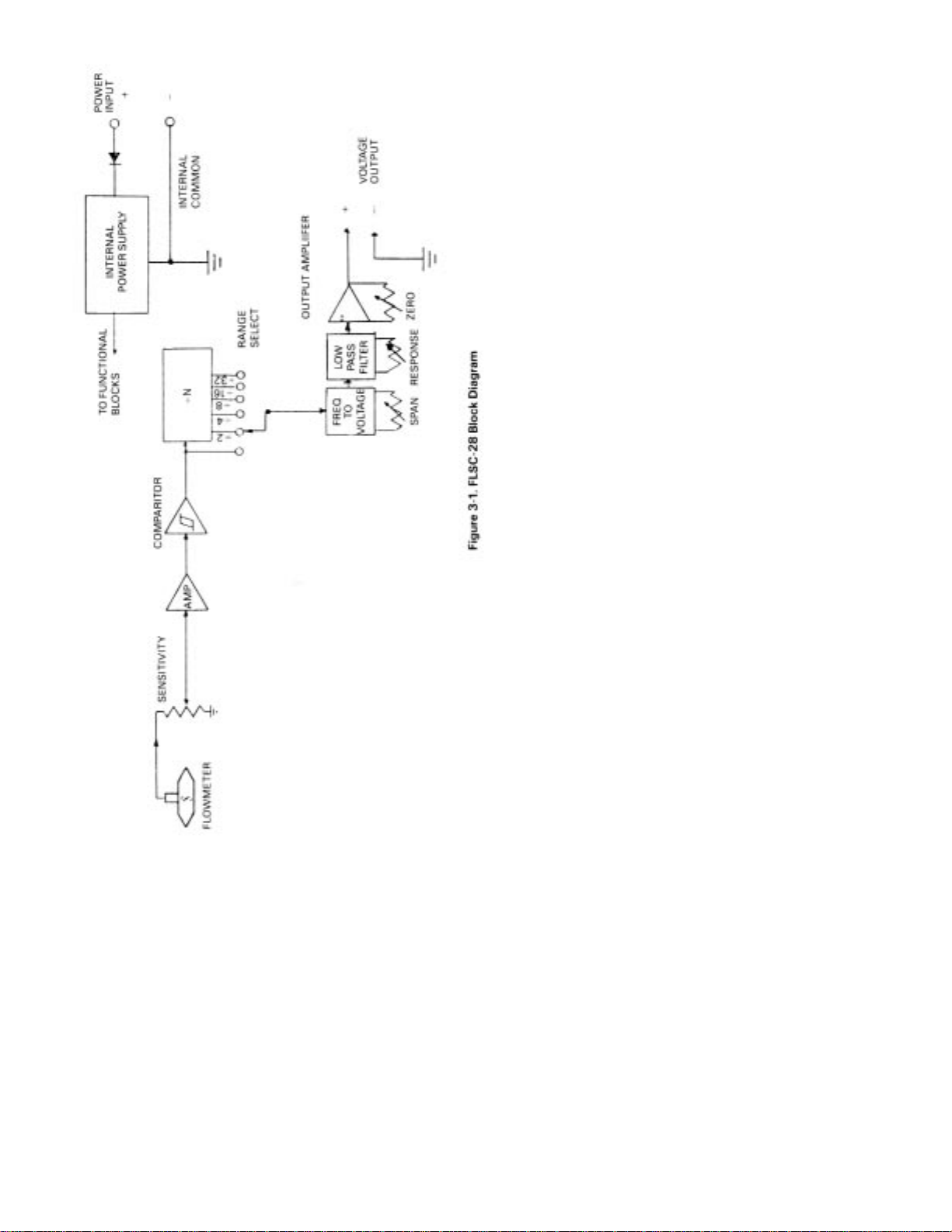
3.1 PRINCIPLE OF OPERATION
A simplified block diagram of the FLSC-28 Frequency to
Current Converter is shown in Figure 3-1. Key functional blocks
as well as flow information are designated. The basic operation
of the system is as follows.
The frequency signal from the flowmeter is connected to the
FLSC-28 with a twisted shielded pair cable. The signal enters the
SENSITIVITY control which is used to reject unwanted noise by
raising the trigger threshold above the background noise present.
The low level flowmeter signal is then passed through a signal
conditioning chain where it is filtered, amplified and shaped into a
train of digital pulses whose frequency is related to the volume flow
rate and where each pulse represents a discrete volume of fluid.
The signal entering the frequency to voltage converter is passed
through a combination of a divide by N and a DIP switch
matrix. The ON output is chosen whose pulse rate is between 75
and 150 Hz at the maximum flow rate measured. This scaled
pulse rate is then filtered into an analog voltage. This voltage is
proportional to volumetric flow rate.
The resulting output voltage related to flow is then fed into the
output amplifier. The output amplifier is a voltage to current
amplifier and offers ZERO and SPAN adjustments and is
available in the process range of 0-5 Vdc.
The precision power supply filters and regulates the input
power and generates the internal 7.5 Vdc power for all circuits
as well as providing reverse polarity protection.
Page 25
20
Page 26
21
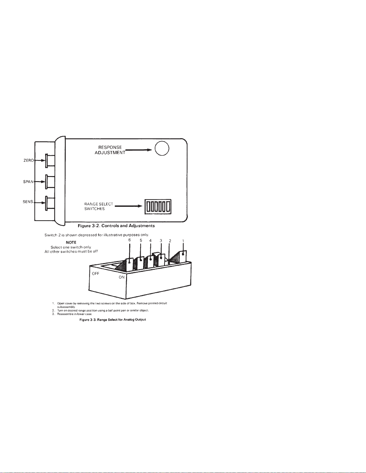
3.2 CONTROLS AND ADJUSTMENTS (See Figure 3-2.)
SENS A single turn control used to set the threshold
sensitivity level above the ambient noise pickup.
RANGE A dual in line (DIP) switch located within the
enclosure (see Figure 3-3 and Table 3-1) which is
used to program the module to accept an input
frequency range.
SPAN A multiple turn adjustment which is used to set
the voltage output signal to the desired span
corresponding to the equivalent flow range (i.e., 0
to 5V corresponding to 0-100 GPM).
ZERO A multiple turn adjustment which is used to set
out put signal with no flow to the desired “zero”
value (i.e., 0.00V dc).
RESPONSE A multiple turn adjustment which is used to set
the response time of the analog output.
Page 27

22
SECTION 4 CALIBRATION OF ANALOG OUTPUT
4.1 INTRODUCTION
In general, all flow measurement systems supplied by OMEGA
Engineering have been factory calibrated as specified by the
user, at the time of purchase.
All systems which underwent such a factory calibration have a
calibration card attached prior to shipment. This card contains
the details of analog outputs as well as other useful calibration
data.
Field calibration is only required when a change has occurred or
is sought to the measuring system. Such a change may be due to
repair, replacement or recalibration of the flowmeter, or perhaps
a change in the analog output span.
4.2 CALIBRATION PROCEDURE
Begin by determining the equivalent maximum volumetric flow
rate in GPM, expected by the application, term this GPM
(MAX). GPM (MAX) may be calculated based on the analog
output scale requirements or may be the maximum flow rate
listed on the flowmeter’s calibration sheet (supplied with
flowmeter
From the calibration constant (or K Factor) listed on the data
sheet for the flowmeter, obtain the frequency corresponding to
GPM (MAX) using Equation #1 and designate this frequency F
(MAX).
Equation #1 F
MAX = KAVE X
GPM
MAX
60
The analog output of the FLSC-28 may be calibrated with the aid
of an external oscillator used in conjunction with a frequency
counter.
TABLE 3-1
RANGE SELECT
Range Select For F Max.
Switch Position
1 75 to 150
2 150 to 300
3 300 to 600
4 600 to 1200
5 1200 to 2400
6 2400 to 4800
Page 28

23
The external oscillator is used to supply a test frequency. In this
method, the external oscillator is connected to the signal input
terminals as shown in Figure 4-1. The oscillator’s output
frequency is set to equal F (MAX) as indicated on the frequency
counter. Power is supplied from a DC source and the analog
output voltage is measured with a digital voltmeter.
1. The course range adjustment is accomplished by selecting a
switch position on a DIP switch located on the PCA-66 printed
circuit card. See Table 3-1 to determine required switch position
and set into switch as shown in Figure 3-3 for anticipated F MAX.
It is necessary to open the cover of the enclosure by removing two screws
on side of box and lifting cover. Two printed circuit cards are attached. The
“RANGE” Dip Switch may be programmed with a pen. Input power should
be removed during this step.
2. Zero Adjustment
a. The redual DC voltage at the output of the FLSC-28 may be
reduced to a low value (a few millivolts) with the aid of the
zero adjustment.
b. Apply the proper DC voltage to the power input. Turn the
input frequency off.
c. Turn the zero control CCW until no further decrease in the
output level is observed. Then turn the zero control CW
until the zero voltage starts to just increase.
3. Span Adjustment
a. Turn the input frequency on and adjust frequency to obtain
FMAX.
b. Adjust the span control to obtain the span voltage on the
output (5.000 Vdc)
4. Response Adjustment (Internal - located on the PCA-66
printed circuit card, see Figure 3-2)
a. The FLSC-28 is provided with an adjustable response trim
control which allows the user to control the response time
to obtain either fast response or minimum ripple.
b. To slow down response turn the response control CCW, to
speed up response turn the response control CW. The
maximum number of turns is 20 on this control. The control
will not be damaged if the end stops are reached and a
slipping action will be felt.
5. Sensitivity Adjustment
a. The sensitivity adjustment is generally left in the full CW
position and is adjusted in the final installation only when f else
pickup occurs during periods of no flow. See Sect. 3 Operation.
NOTE
Page 29
24
Page 30

25
TROUBLESHOOTING
In case of an inoperable or malfunctioning system the following
procedures can be used to isolate the faulty wiring, printed
circuit boards and/or alternate causes. The majority of repairs
can be made in the field thereby reducing the time a unit is out
of service.
The necessary documentation is contained within this manual
with the exception of the calibration data sheet for the turbine
flowmeter. This calibration is supplied separately.
Factory consultation is available to assist in diagnosing
problems. Please note that in some cases factory repairs can be
performed more easily than can be accomplished in the field.
Failure conditions are listed and the possible corrective actions
given to eliminate the observed problem.
Proper operation of the FLSC-28 can be assumed when with
power applied to the unit, the analog output produces a voltage
output signal of 0-5 Vdc with a span corresponding to that
already established by the calibration procedure.
OBSERVED CONDITION CORRECTIVE ACTION
A. Analog Output 1 .Noise on input. Slowly turn
With No Flow SENS pot CCW until false
indication stops.
NOTE: In fully CCW position
the unit will not operate.
2. Replace pickup coil
3. Defective FLSC-28, repair or
replace.
B. Incorrect Zero Reading 1. Verify that power supply
With No Flow voltage is within limit.
2. Unit is out of calibration - recalibrate.
3. Defective FLSC-28, repair or
replace.
C. Voltage Exceeds 1. Flowmeter being used beyond
Desired Span calibrated span of FLSC-28
2. Calibration of FLSC-28
incorrect. Recalibrate,
3. Defective unit, repair or replace.
Page 31

26
OBSERVED CONDITION CORRECTIVE ACTION
A. Analog Output 1 .Noise on input. Slowly turn
With No Flow SENS pot CCW until false in
dication stops.
NOTE: In fully CCW position
the unit will not operate.
D. Incorrect Analog 1 .Load resistance too small.
Output with Flow 2. Noise pickup present. Adjust
Sensitivity.
3. Calibration of FLSC-28
incorrect. Recalibrate.
E. Large Ripple on 1 .Wrong “Range” switch
Analog Output selected. Recalibrate.
2. Flowmeter being operated
below range. Adjust response
control to minimize ripple.
SECTION 6 SPECIFICATIONS
INPUT. Input protected, RF and band pass filtered, adjustable
trigger level,
Input Impedance - 40 kilohm (nominal)
Trigger Sensitivity - 10 millivolt RMS (minimum) 10 to 1000 Hz
Over Voltage - 120 volts RMS absolute (maximum)
VOLTAGE OUTPUT: Accuracy ±0.05% of full scale ±200
PPM/°C Range 0-5V
Impedance less than 10 ohms.
Response time .5 - 1.5 seconds, for 10 to 90%, adjustable. Output
ripple less than 0.2% of F.S.
Load resistance output can source up to 10 mA into a grounded
load only.
INPUT POWER: 10-40 Vdc @ 10 mA
TEMPERATURE RANGE: 0°-70°C (32° to 158°F)
ELECTRICAL CONNECTIONS: Screw Terminals
MAXIMUM LEAD LENGTH: 100 ft. of 24 gage copper wire
ELECTRICAL HOUSING: Class 1, Group D
Class 11 Group E, F, G
Class III
Page 32
27
Page 33

28
TABLE OF, CONTENTS
FLSC-34 SIGNAL CONDITIONER
SECTION PAGE
SECTION 1 INTRODUCTION ............................................ 29
SECTION 2 INSTALLATION .............................................. 29
2.1 Unpacking ........................................................................ 29
2.2 Installation of the FLSC-34 ............................................ 29
SECTION 3 OPERATION ..................................................... 32
3.1 Principle of Operation .................................................... 32
3.2 Controls and Adjustments ............................................ 32
3.2.1 Replacing the Fuse .......................................................... 32
3.2.2 Range Select for Analog Output ................................... 35
SECTION 4 CALIBRATION OF ANALOG OUTPUT .... 35
4.1 Introduction ..................................................................... 35
4.2 Procedure ......................................................................... 36
SECTION 5 TROUBLESHOOTING .................................... 38
SECTION 6 SPECIFICATIONS ............................................ 39
Page 34

29
SECTION 1 INTRODUCTION
The OMEGA®FLSC-34 High Accuracy Integral Signal
Conditioners are designed for direct mounting onto OMEGA
Series FTB-100 and 200 Turbine Meters.
The input circuitry of the FLSC-34 signal conditioner has been
designed to receive and condition the low level turbine meter
signals while rejecting unwanted noise and spurious signals. A
signal threshold control is provided which allows the user to set
the input sensitivity above the ambient noise level, thereby
eliminating any false signal on the output.
The FLSC-34 runs off 115 Vac and provides both an unscaled
pulse output (CMOS, TTL compatible) and a 420 mA output. A
zero and span potentiometer allow for simple field adjustment
of the analog outputs from the signal conditioners.
SECTION 2 INSTALLATION
2.1 UNPACKING
Remove the Packing List and verify that all equipment has been
received. If there are any questions about the shipment, please
call OMEGA Customer Service Department.
Upon receipt of shipment, inspect the container and equipment
for any signs of damage. Take particular note of any evidence of
rough handling in transit. Immediately report any damage to
the shipping agent.
The carrier will not honor any claims unless all shipping material is saved f
or their examination. After examining and removing contents, save packing
material and carton in the event reshipment is necessary.
2.2 INSTALLATION OF THE FLSC-34
The FLSC-34 should be placed in a convenient location which
maintains access to the unit should repairs or readjustment be
required.
If the unit is mounted on a turbine flowmeter in an explosion
proof conduit enclosure, orientate the flowmeter and run
conduit to prevent the accumulation of moisture in the conduit
enclosure as much as is practical. In addition, assure electronics
will not be overheated by hot process lines.
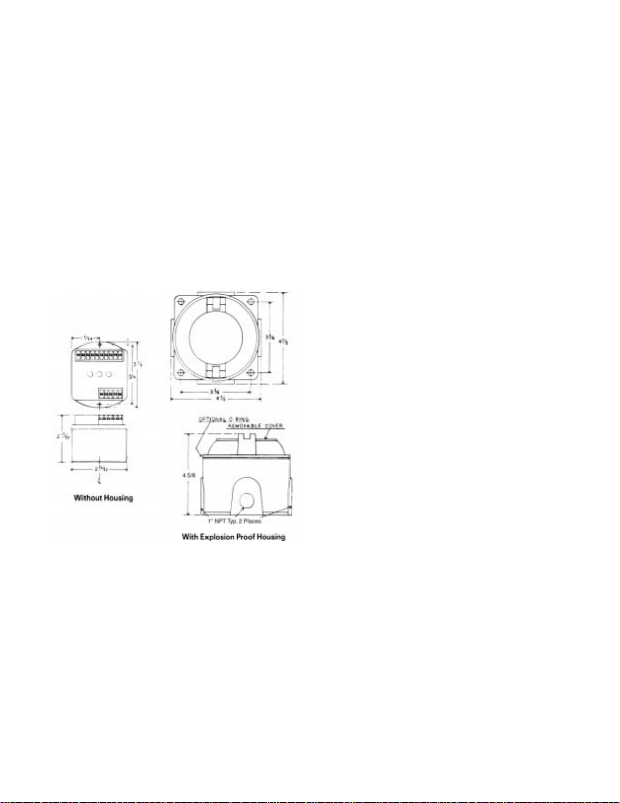
Refer to Figure 2-1 for outline dimensions. Drill appropriate
mounting holes as required.
NOTE
Page 35
30
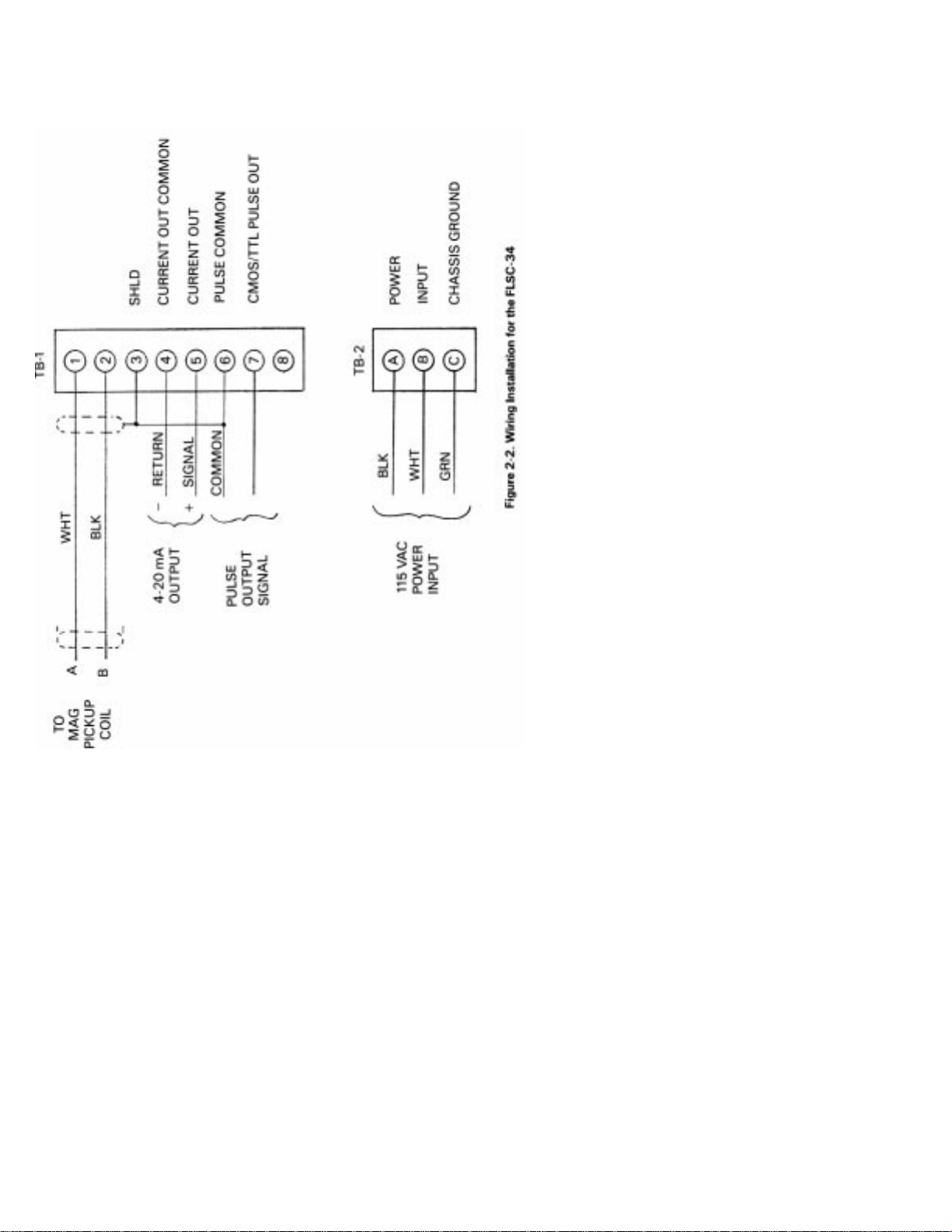
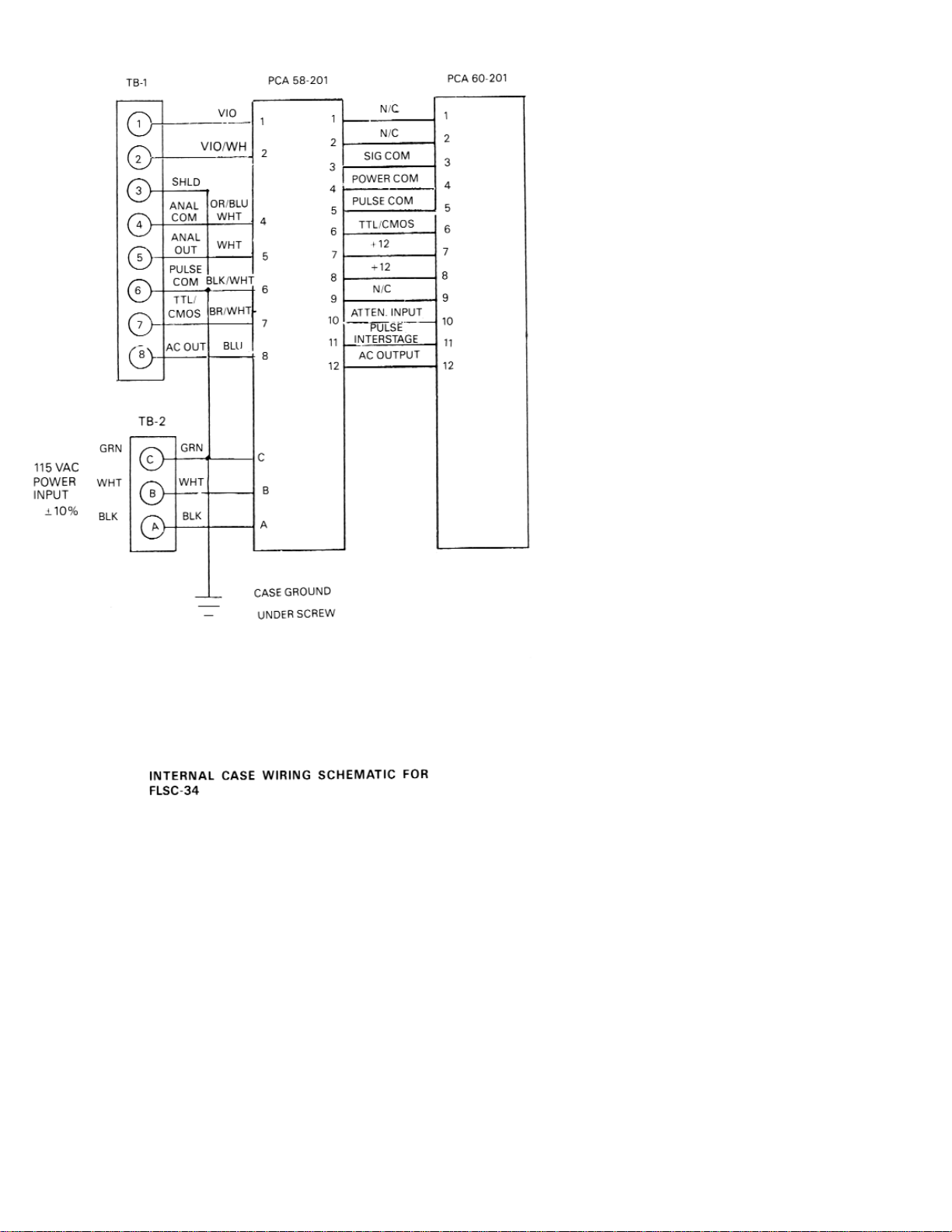
Refer to Figure 2-2, wiring installation drawing for appropriate
terminals for interconnections. The signal leads from the turbine
should be shielded whenever the FLSC-34 is not integrally
mounted. Ground shield on one end only. If desired, use solder
lug provided on ground stud. Connections to the terminal block
should be carefully dressed to avoid having bare wires extend
pass the screw clamp on the terminal block. This is particularly
important for units mounted within the explosion proof
enclosure. Wires should be neatly dressed near bottom of
enclosure to assure wiring will not become fouled when cover is
installed.
Connect two conductor shielded cable from flowmeter. Connect
shield to FLSC-34 only.
Line power connection should be made through a circuit
breaker so that power can be turned off while servicing the
FLSC-34. Power is 117 Vac ±10%, an earth ground connection is
also required.
Pulse output is CMOS/TTL compatible. Wire to appropriate
terminal, see Figure 2-2.
For Analog Output connect wiring to appropriate terminals and
load. A shielded, twisted pair wire is recommended. Ground
shield on one end only. Use same precautions as described for
flowmeter input signal.
Figure 2-1. Outline and Intallation Dimensions
Page 36
31
Page 37

32
SECTION 3 OPERATION
Perform any purging of piping with spool piece in place. Once
completed, install the flowmeter and connect cabling to pickup
coil. If false counting action occurs turn sensitivity control
clockwise.
The pulse output and analog output commence with flow
through the flowmeter.
For the analog output, the span is that established by either the
factory calibration or field calibration. The range is 4-20 mA DC
into a maximum of 325 ohms of loop resistance.
3.1 PRINCIPLE OF OPERATION
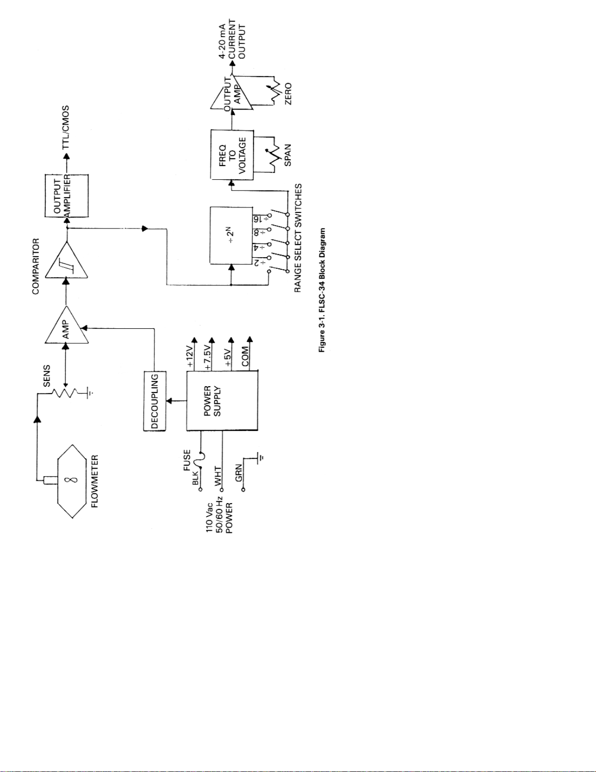
A simplified block diagram of the FLSC-34 Frequency/Current
Flow Converter Subsystem is shown in Figure 3-1. Key
functional blocks as well as information flow are designated.
The basic operation of the system is as follows.
The frequency signal f rom the turbine flowmeter is connected
to the FLSC-34 with a twisted pair shielded cable. The signal
enters through the SENSITIVITY control which is used to reject
unwanted noise by raising the trigger threshold above the
background noise present.
The low level flowmeter signal is then passed through a signal
conditioning chain where it is amplified and shaped into a train of
digital pulses whose frequency is related to the volume f low rate.
The signal entering the frequency to analog converter is passed
through a combination of a divide by N and a DIP switch
matrix. The ON output is chosen whose pulse rate is between 75
and 150 Hz at the maximum flow rate to be measured. This
scaled pulse rate is fed to a precision monostable circuit. The
output of the monostable circuit is then filtered into an analog
voltage that is proportional to volumetric flow rate.
The output amplifier is a voltage to current amplifier. It offers
zero and span available in a standard process range of 4-20 mA.
The Power Supply provides for operating bias voltage for all
internal circuitry. The pulse output amplifier provides a
TTL/CMOS compatible square pulse of 5V amplitude. The
output amplifier is buffered from the signal driving the analog
output.
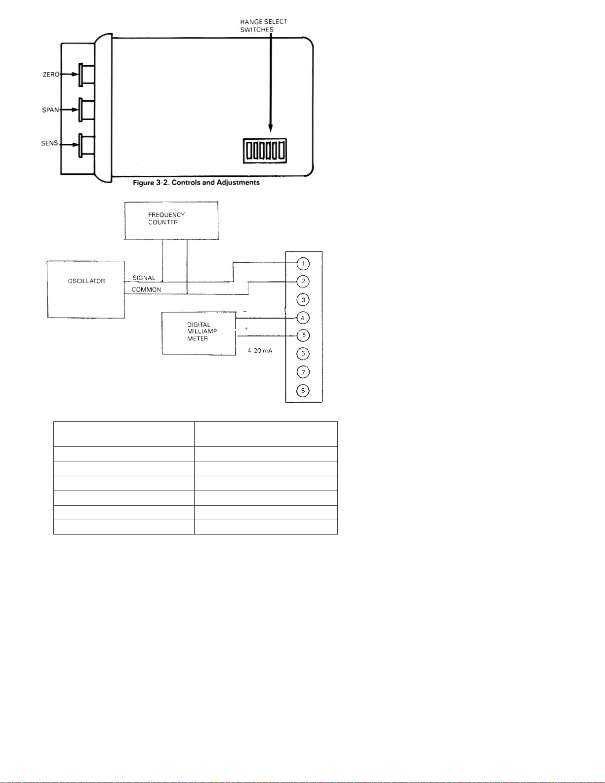
3.2 CONTROLS AND ADJUSTMENTS (See Figure 3-2.)
FUSE A circuit protection device located inside of case (see
paragraph 3.2.1)
SENS. A multiple turn control used to set the threshold
sensitivity level above the ambient noise pickup.
Page 38
33
Page 39
34
TABLE 3-1 RANGE SELECT
Range Select For F Max.
Switch Position
1 75 to 150
2 150 to 300
3 300 to 600
4 600 to 1200
5 1200 to 2400
6 2400 to 4800
Page 40

35
RANGE A dual in line (DIP) switch located on the FICA61
board (see Figure 3-3 and paragraph 3.2.2) which is
used to program the module to accept an input
frequency range.
SPAN A multiple turn adjustment which is used to set the
voltage output signal to the desired span
corresponding to the equivalent flow range (i.e., 4 to
20mA corresponding to 0-100 GPM).
ZERO A multiple turn adjustment which is used to set
output signal with no flow to the desired “zero”
value (i.e., 4 mA).
3.2.1 Replacing the Fuse (see Figure 3-2)
1. Turn off power to the FLSC-34,
2. Remove the two screws from sides of case.
3. Lift off cover and remove printed circuit sub-assembly.
4. Pull fuse from fuse socket using fingers (Pliers are not
recommended).
5. Install new fuse.
6. Reassemble into lower case.
3.2.2 Range Select for Analog Output
1. Turn power to FLSC-34 off.
2. Remove the two screws from sides of case.
3. Lift off cover and remove printed circuit sub-assembly.
4. Turn “on” desired range position using a ball point pen or
similar object. (Refer to Figure 3-3 and Table 3-1.)
5. Reassemble into lower case.
SECTION 4 CALIBRATION OF ANALOG OUTPUT
4.1 INTRODUCTION
In general, all flow measurement systems supplied by OMEGA
Engineering have been factory calibrated as specified by the
user, at the time of purchase.
Field calibration is only required when a change has occurred or
is sought to the measuring system. Such a change may be due to
repair, replacement or recalibration of the flowmeter, or perhaps
a change in the analog output span.
Page 41

36
4.2 PROCEDURE
Begin by determining the equivalent maximum volumetric flow
rate in GPM, expected by the application, term this GPM
(MAX). GPM (MAX) may be calculated based on the analog
output scale requirements or may be the maximum flow rate
listed on the flowmeter’s calibration sheet.
From the calibration constant (or K Factor) listed on the data
sheet for the flowmeter, obtain the frequency corresponding to
GPM (MAX) using Equation #1 and designate this frequency F
(MAX),
Equation #1 F
MAX = KAVE X
GPM
MAX
60
The analog output of the FLSC-34 may be calibrated with the aid
of an external oscillator used in conjunction with a frequency
counter.
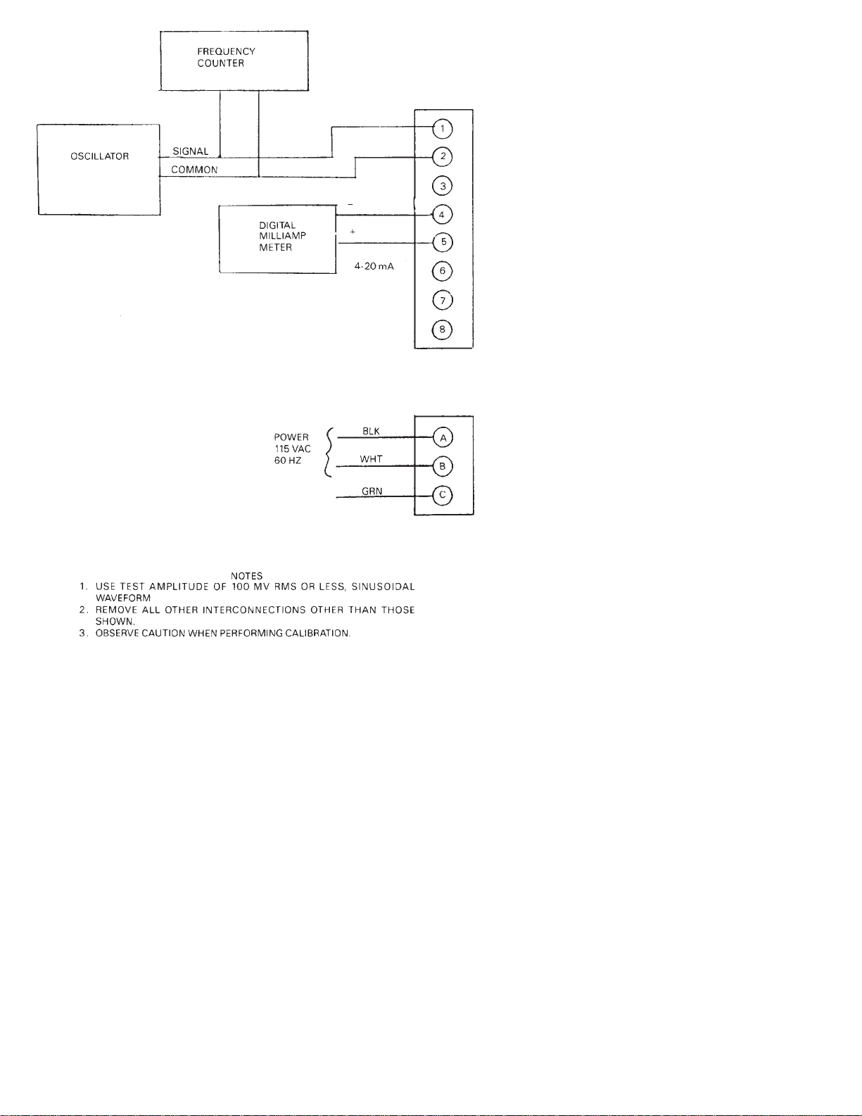
The external oscillator is used to supply a test frequency. In this
method, the external oscillator is connected to the signal input
terminals as shown in Figure 4-1. The oscillator’s output
frequency is set to equal F (MAX) as indicated on the frequency
counter.
1. The course range adjustment is accomplished by selecting a
switch position on a DIP switch located on the PCA61 printed
circuit card. See Table 3 1 to determine required switch
position and set into switch as shown in Figure 3-3 for
anticipated F MAX.
It is necessary to open the cover of the enclosure by removing two screws
on side of box and lifting cover. Two printed circuit cards are attached. The
“RANGE” Dip Switch may be programmed with a pen. Input power should
be removed during this step.
2. Connect a digital milliampmeter or equivalent across the
current output terminals.
3. Adjust ZERO control for desired zero current (i.e., 4.00 mA)
4. Turn SPAN POT fully CCW until detent is felt or 25 turns.
5. Inject the Test Frequency equal to F MAX while adjusting
SPAN for current equal to 20 mA ±20 mA. See test setup
shown in Figure 4-1.
Repeat steps 4 and 5 until no change is observed.
NOTE
Page 42
37
Figure 4-1. Calibration Set-Up
Page 43

38
SECTION 5 TROUBLESHOOTING
In case of an inoperable or malfunctioning system the following
procedures can be used to isolate the faulty wiring, printed circuit
boards and/or alternate causes. The majority of repairs can be.
made in the field thereby reducing the time a unit is out of service.
The necessary documentation is contained within this manual
with the exception of the calibration data sheet for the turbine
flowmeter. This calibration is supplied with the turbine flowmeter.
Factory consultation is available to assist in diagnosing
problems. Please note that in some cases factory repairs can be
performed more easily than can be accomplished in the field.
Failure conditions are listed and the possible corrective actions
given to eliminate the observed problem.
Proper operation of the FLSC-34 can be assumed when with
power applied to the unit:
1. The pulse output produces a pulse train of the desired
amplitude when flow through the flow transducer occurs.
2. The analog output produces a current output signal of 4-20
mA with a span corresponding to that established by the
calibration procedure.
OBSERVED CONDITION PROBLEM CORRECTIVE ACTION
A. No Pulse Output 1. Inspect terminal strip wiring for
conformity,to the installation
instructions and for acceptable
workmanship.
2. Verify fuse is good with an ohm
meter.
3. Determine if flowmeter rotor is
fouled.
4. Defective pickup coil. Replace
5. Defective cable. Replace.
6. Defective FLSC-34. Repair or
replace.
7. Sensitivity potentiometer turned
fully clockwise - unit will not
function properly.
B. Pulsing Output With 1. Defective pickup coil. Replace.
No Flow
2. Defective cable. Replace.
3. Defective FLSC-34. Repair or
replace.
Page 44

39
C. Analog Output 1. Improper wiring terminations.
Correct wiring.
2. FLSC-34 improperly calibrated.
Recalibrate.
3. Defective circuitry within the
FLSC-34. Factory repair FLSC-34.
Refer to flowmeter operator’s manual for repair instructions for the turbine
flowmeter.
SECTION 6 SPECIFICATIONS
INPUT: Input protected, RF and band pass filtered, adjustable
trigger level,
Input Impedance 40 ohm (nominal)
Trigger Sensitivity 10 millivolt RMS (minimum) 10 Hz to
1000 Hz Over Voltage - 120 volts RMS absolute (maximum)
ANALOG OUTPUT: Range 4 to 20 mA.
Controls - Non-interacting zero and span adjustments.
Accuracy ±0.1% F. S. 200 PPM/°C
Maximum Impedance - 325 ohms.
F. S. Frequency Range 75 Hz to2500 Hz (DIP SWITCH
SELECTABLE)
PULSE OUTPUT: TTL/CMOS COMPATIBLE
LOGIC 1; 2.4V AT - .800 mA
LOGIC 0; 0.4 V maximum at 100 ma
INPUT POWER: 115 Vac 50/60 Hz
TEMPERATURE RANGE: 0°-70°C (32° to 158°F)
ELECTRICAL CONNECTIONS: Screw Terminals
MAXIMUM LEAD LENGTH: 1000 ft. of 24 gage copper wire
ELECTRICAL HOUSING: Class 1, Group D
Class 11 Group E, F, G
Class III
NOTE
Page 45
40
Page 46

41
TABLE OF, CONTENTS
FLSC-35B SIGNAL CONDITIONER
SECTION PAGE
SECTION 1 INTRODUCTION ............................................ 42
SECTION 2 INSTALLATION .............................................. 42
2.1 Unpacking ....................................................................... 42
2.2 Installation of the FLSC-35B ......................................... 42
SECTION 3 OPERATION ..................................................... 45
3.1 Principle of Operation ................................................... 45
3.2 Controls and Adjustments ........................................... 45
3.2.1 Replacing the Fuse ......................................................... 48
3.2.2 Range Select for Analog Output .................................. 48
SECTION 4 CALIBRATION OF ANALOG OUTPUT .... 48
4.1 Introduction .................................................................... 48
4.2 Procedure ........................................................................ 49
SECTION 5 TROUBLESHOOTING .................................... 51
SECTION 6 SPECIFICATIONS ............................................ 52
Page 47

42
SECTION 1 INTRODUCTION
The OMEGA®FLSC-35B High Accuracy Integral Signal
Conditioner is designed for direct mounting onto OMEGA
Series FTB-100 and 200 Turbine Meters.
The input circuitry of the signal conditioners has been designed
to receive and condition the low level turbine meter signals
while rejecting unwanted noise and spurious signals. A signal
threshold control is provided which allows the user to set the
input sensitivity above the ambient noise level, thereby
eliminating any false signal on the output.
The FLSC-35B runs off 115 VAC and provides an unscaled pulse
output (CMOS, TTL compatible) and a 0-5 V output. A zero and
span potentiometer allow for simple field adjustment of the
analog output from the signal conditioner.
SECTION 2 INSTALLATION
2.1 UNPACKING
Remove the Packing List and verify that all equipment has been
received. If there are any questions about the shipment, please
call OMEGA Customer Service Department.
Upon receipt of shipment, inspect the container and equipment
for any signs of damage. Take particular note of any evidence of
rough handling in transit. Immediately report any damage to
the shipping agent.
The carrier will not honor any claims unless all shipping material is saved
for their examination. After examining and removing contents, save
packing material and carton in the event reshipment is necessary.
2.2 INSTALLATION OF THE FLSC-35B
The FLSC-35B should be placed in a convenient location which
maintains access to the unit should repairs or readjustment be
required.
If the unit is mounted on a turbine flowmeter in an explosion
proof conduit enclosure, orientate the flowmeter and run
conduit to prevent the accumulation of moisture in the conduit
enclosure as much as is practical. In addition, assure electronics
will not be overheated by hot process lines.
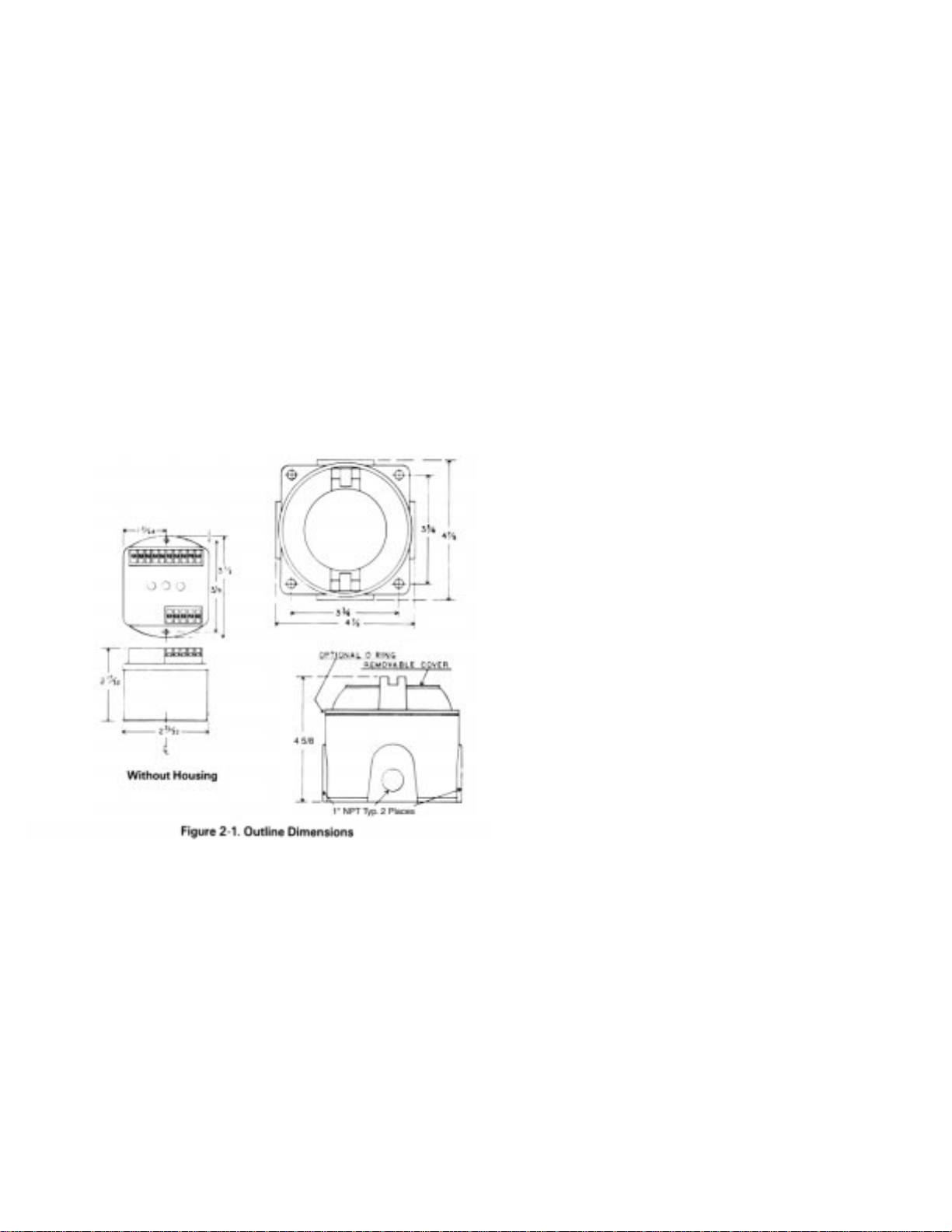
Refer to Figure 2-1 for outline dimensions. Drill appropriate
mounting holes as required.
NOTE
Page 48
43
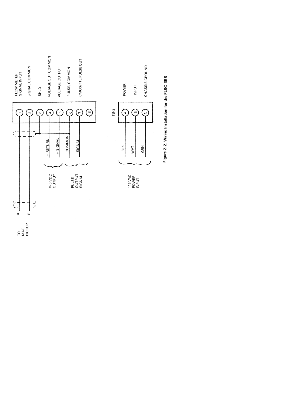
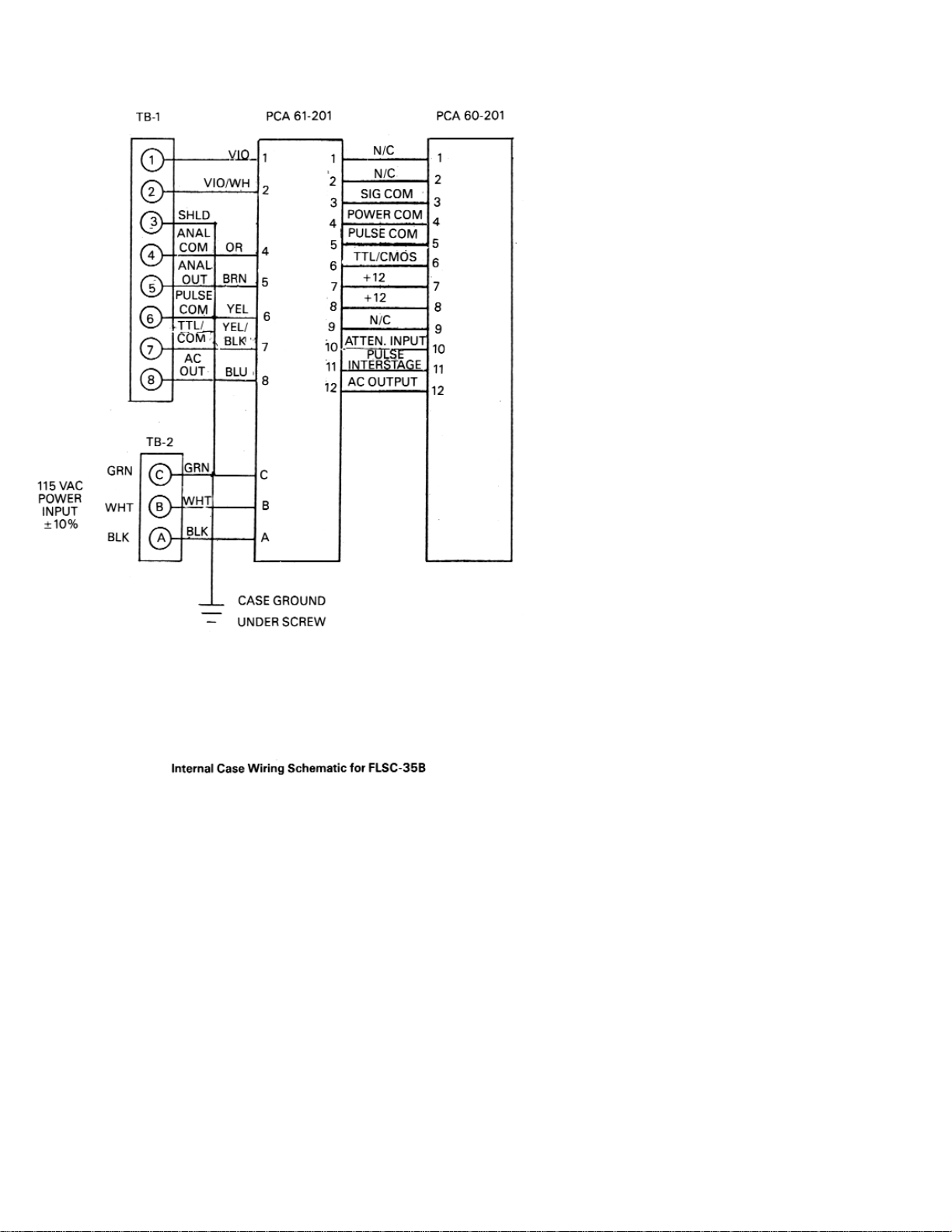
Refer to Figure 2-2, wiring insulation, for appropriate terminals
for interconnections. The signal leads from the turbine should be
shielded whenever FLSC-35B is not integrally mounted. Ground
shield on one end only. If desired, use solder lug provided on
ground stud. Connections to the terminal block should be
carefully dressed to avoid having bare wires extend pass the
screw clamp on the terminal block. This is particularly
important for units mounted within the explosion proof
enclosure. Wires should be neatly dressed near bottom of
enclosure to assure wiring will not become fouled when cover is
installed.
Connect two conductor shielded cable from flowmeter. Connect
shield to FLSC-35B only.
Line power connections should be made through a circuit
breaker so that power can be turned off while servicing the
FLSC-35B. Power is 117 VAC ±10%, an earth ground connection
is also required.
Pulse output is CMOS/TTL compatible. Wire to appropriate
terminal, see Figure 2-2.
For analog output connect wiring to appropriate terminals and
load. A shielded, twisted pair wire is recommended. Ground
shield on one end only. Use same precautions as described for
flowmeter input signal.
Page 49
44
Page 50

45
SECTION 3 OPERATION
Perform any purging of piping with spool piece in place. Once
completed, install the flowmeter and connect cabling to pickup coil.
If false counting action occurs turn Sensitivity control clockwise.
The pulse output and analog output commence with flow through
the flowmeter.
For the analog output, the span is that established by either the
factory calibration or field calibration. The range is 05 Vdc into a
maximum of 1000 ohms of loop resistance.
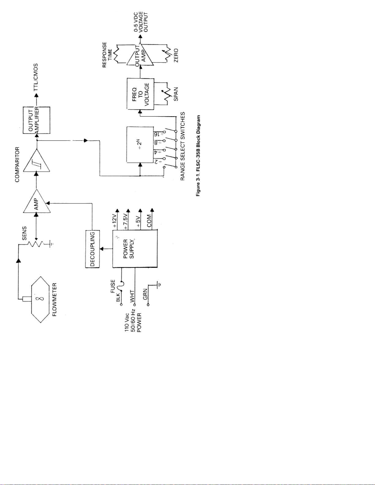
3.1 PRINCIPLE OF OPERATION
A simplified block diagram of the FLSC-36B Frequency/Voltage
Flow Converter Subsystem is shown in Figure 3-1. Key
functional blocks as well as flow information are designated.
The basic operation of the system is as follows.
The frequency signal from the turbine flowmeter is connected to
the FLSC-35B with a twisted pair shielded cable. The signal
enters through the sensitivity control which is used to reject
unwanted noise by raising the trigger threshold above the
background noise present.
The low level flow meter signal is then passed through a signal
conditioning chain where it is amplified and shaped into a train
of digital pulses whose frequency is related to the volume flow
rate
The signal entering the frequency to analog converter is passed
through a combination of a divide by IN and a DIP switch
MATRIX. The ON output is chosen whose pulse rate is between
75 and 150 Hz at the maximum flow rate to be measured. This
scaled pulse rate is then fed to a precision monostable circuit.
The output of the monostable is then filtered into an analog
voltage that is proportional to volumetric flow rate.
The output amplifier is a voltage to voltage amplifier. It offers
zero and span available in a process range of 0 to 5 Vdc.
The Power Supply provides for operating bias voltage for all
internal circuitry.
The pulse output amplifier provides a TTL/CMOS compatible
square pulse of 5 volt amplitude. The output amplifier is
buffered from the signal driving the analog output.
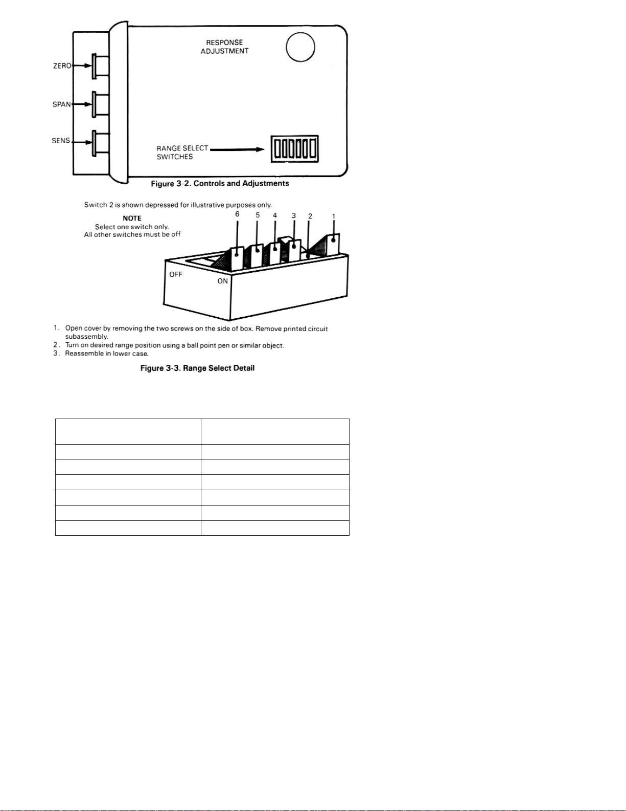
3.2 CONTROLS AND ADJUSTMENTS (See Figure 3-2.)
FUSE, A circuit protection device located inside of case (see
paragraph 3.2.1)
SENS. A multiple turn control used to set the threshold
sensitivity level above the ambient noise pickup.
Page 51
46
Page 52
47
TABLE 3-1
RANGE SELECT
Range Select For F Max.
Switch Position
1 75 to 150
2 150 to 300
3 300 to 600
4 600 to 1200
5 1200 to 2400
6 2400 to 4800
Page 53

48
FUSE, A circuit protection device located inside of case
(see paragraph 3.2.1)
SENS. A multiple turn control used to set the threshold
sensitivity level above the ambient noise pickup.
RANGE A dual in line (DIP) switch located on the PCA61
board (see Figure 3-3 and paragraph 3.2.2.) which
is used to program the module to accept an input
frequency range.
SPAN A multiple turn adjustment which is used to set
the voltage output signal to the desired span
corresponding to the equivalent flow range (i.e., 0
to 5V corresponding to 0-100 GPM).
ZERO A multiple turn adjustment which is used to set
output signal with no flow to the desired “zero”
value i.e., 0.00 Vdc).
RESPONSE An internal, multiple turn adjustment which is used
to adjust the response time of the analog output.
3.2.1 Replacing the Fuse (see Figure 3-2)
1. Turn off power to the FLSC-35B.
2. Remove the two screws from sides of case.
3. Lift off cover and remove printed circuit sub-assembly.
4. Pull fuse from fuse socket using fingers pliers are not
recommended).
5. Install now fuse.
6. Reassemble into lower case.
3.2.2 Range Select for Analog Output
1. Turn power to FLSC-35B off.
2. Remove the two screws from sides of case.
3. Lift off cover and remove printed circuit sub-assembly.
4. Turn “on” desired range position using a ball point pen or
similar object (Refer to Figure 3-3 and Table 3-1).
5. Reassemble into lower case.
SECTION 4 CALIBRATION OF ANALOG OUTPUT
4.1 INTRODUCTION
In general, all flow measurement systems supplied by OMEGA
Engineering ˆˆhave been factory calibrated as specified by the
user, at the time of purchase.
Field calibration is only required when a change has occurred or
is sought to the measuring system. Such a change may be due to
repair, replacement or recalibration of the flowmeter, or perhaps
a change in the analog output span.
Page 54

49
4.2 PROCEDURE
Begin by determining the equivalent maximum volumetric low
rate in GPM, expected by the application, term this GPM
(MAX). GPM (MAX) may be calculated based on the analog
output scale requirements or may be the maximum flow rate
listed on the flowmeter’s calibration sheet.
From the calibration constant (or K Factor) listed on the data
sheet for the flowmeter, obtain the frequency corresponding to
GPM (MAX) using Equation #1 and designate this frequency F
(MAX).
Equation #1 F
MAX = KAVE X
GPM
MAX
60
The analog output of the FLSC-35B maybe calibrated with the
aid of an external oscillator used in conjunction with a
frequency counter.
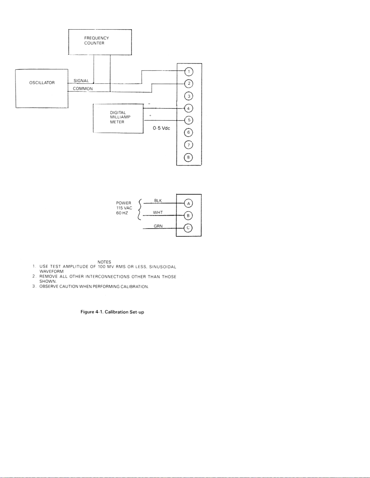
The external oscillator is used to supply a test frequency. In this
method, the external oscillator is connected to the signal input
terminals as shown in Figure 4-1. The oscillator’s output
frequency is set to equal F (MAX) as indicated on the frequency
counter.
1. The course range adjustment is accomplished by selecting a
switch position on a DIP switch located on the PCA61 printed
circuit card. See Table 3 1 to determine required switch
position and set into switch as shown in Figure 3-3 for
anticipated F MAX.
It is necessary to open the cover of the enclosure by removing two screws
on side of box and lifting cover. Two printed circuit cards are attached. The
“RANGE” Dip Switch may be programmed with a pen. Input power should
be removed during this step.
2. Connect a digital voltmeter or equivalent, across the voltage
output terminals.
3. Adjust ZERO control for desired zero voltage (.000 Vdc)
4. Turn SPAN POT fully CCW until detent is felt or 25 turns.
5. Inject the Test Frequency equal to F MAX while adjusting
SPAN for voltage equal to + 5.000V +1 mV. See test setup
shown in Figure 4-1.)
Repeat steps 3 and 4 until no change is observed.
NOTE
Page 55
50
Page 56

51
SECTION 5 TROUBLESHOOTING
In case of an inoperable or malfunctioning system the following
procedures can be used to isolate the faulty wiring, printed circuit
boards and/or alternate causes. The majority of repairs can be
made in the field thereby reducing the time a unit is out of service.
The necessary documentation is contained within this manual
with the exception of the calibration data sheet for the turbine
flowmeter. This calibration is supplied with the turbine flowmeter.
Factory consultation is available to assist in diagnosing
problems. Note that in some cases factory repairs can be
performed more easily than can be accomplished in the field.
Failure conditions are listed and the possible corrective actions
given to eliminate the observed problem.
Proper operation of the FLSC-35B can be assumed when with
power applied to the unit:
1. The pulse output produces a pulse train of the desired
amplitude when flow through the flow transducer occurs.
2. The analog output produces a voltage output signal of 0-5
Vdc with a span corresponding to that established by the
calibration procedure.
OBSERVED CONDITION CORRECTIVE ACTION
A. No Pulse Output 1. Inspect terminal strip wiring for
conformity,to the installation in
instructions and for acceptable
workmanship.
1 . Inspect terminal strip wiring
for conformity to the installation
instructions and for acceptable
workmanship.
2. Verify fuse is good with an
ohm meter.
3. Determine if flowmeter rotor
is fouled.
4. Defective pickup coil. Replace
5. Defective cable. Replace.
6. Defective FLSC-35B. Repair or replace.
7. Sensitivity potentiometer turned
fully clockwise - unit will not
function properly.
B. Pulsing Output 1 . Defective pickup coil. Replace
With No Flow
2. Defective cable. Replace.
3. Defective FLSC-35B, Repair or replace.
Page 57

52
C. Analog Output 1. Improper wiring terminations.
Malfunction Correct wiring.
2. FLSC-35B improperly calibrated.
Recalibrate.
3. Defective circuitry within the
FLSC-35B. Factory repair FLSC-35B.
Refer to flowmeter operator’s manual for repair instructions for the turbine
flowmeter.
SECTION 6 SPECIFICATIONS
INPUT: Input protected, RF and band pass filtered adjustable
trigger level.
Input Impedance 40 kilohm (nominal)
Trigger Sensitivity 10 millivolt RMS (minimum) 10 to 1000 Hz
Over Voltage 120 volts RMS absolute (maximum)
Compatible with magnetic pickoffs.
ANALOG OUTPUT: The analog output is generated by passing
the pulse output frequency signal to a frequency to voltage
converter to generate a voltage proportional to flow rate.
Range 0 to 5 Vdc
Controls - Non interacting zero and span adjustments.
Accuracy ±0.1% F.S. 200 ppm/°C
F.S. Frequency Range 75 Hz to 2500 Hz (DIP SWITCH
SELECTABLE)
Impedance less than 50 ohms
Response time 0.5 to 2 seconds f or 10 to 90%. Adjustable
PULSE OUTPUT CHARACTERISTICS: TTL/CMOS
Compatible option:
Logic 1: 2AV at -.800 mA; Logic 0:0.4V maximum at 100 mA
POWER REQUIREMENTS: 115 Vac 50/60 Hz
TEMPERATURE RANGE: 0°- 70°C Standard
ELECTRICAL HOUSING: Class 1, Group D
Class 11 Group E, F, G
Class III
NOTE
Page 58
53
Page 59

54
TABLE OF, CONTENTS
FLSC-51 and 51B SIGNAL CONDITIONERS
SECTION PAGE
SECTION 1 INTRODUCTION ............................................ 55
SECTION 2 INSTALLATION .............................................. 55
2.1 Unpacking ....................................................................... 55
2.2 Installation of the FLSC-51/51B .................................. 56
SECTION 3 OPERATION ..................................................... 58
3.1 Principle of Operation ................................................... 58
3.2 Start-up Operation ......................................................... 58
3.2.1 General Operation ......................................................... 60
3.2.2 Controls and Adjustments ........................................... 60
SECTION 4 CALIBRATION OF ANALOG OUTPUT .... 61
4.1 Introduction .................................................................... 61
4.2 Procedure ........................................................................ 61
SECTION 5 TROUBLESHOOTING .................................... 62
SECTION 6 SPECIFICATIONS ............................................ 63
Page 60

55
SECTION 1 INTRODUCTION
The OMEGA” FLSC-51 and 51B High Accuracy Integral Signal
Conditioners are designed for direct mounting onto OMEGA
Series FTB-100 and 200 Turbine Meters.
The FLSC-51/51B provides a scaled pulse output which may be
field calibrated to the desired number of pulses per unit volume.
Typical outputs which may be realized are one pulse per gallon,
or ten pulses per liter, etc.
This interface subsystem approach allows for direct interfacing with
a host system without requiring special software considerations
being given to the method of input and storage of flowmeter
calibration constants. Partitioning of the system by this means will
also allow for easy field adjustment when such calibration constants
change due to repair or replacement. The calibration scaling factor is
entered into a digital thumbwheel switch matrix.
The input signal conditioning circuitry is designed to accept the
low level flowmeter signal while rejecting unwanted noise and
spurious signals. A signal threshold control is provided which
allows the user to set the input sensitivity above the ambient
noise level, thereby eliminating any false signal on the output.
Two outputs are available, providing flexibility in the interface
as required by the host system. The output is available in the
form of CMOS/TTL compatible pulse If or the FLSC-51) and in
the form of an open collector pulse If or the FLSC-51B). The
pulse duration is.2 ms for the FLSC-51 for use with digital
electronics. The pulse duration is 50 ms for the FLSC-51B for use
with electromechanical totalizers.
SECTION 2 INSTALLATION
2.1 UNPACKING
Remove the Packing List and verify that all equipment has been
received. If there are any questions about the shipment, please
call OMEGA Customer Service Department.
Upon receipt of shipment, inspect the container and equipment
for any signs of damage. Take particular note of any evidence of
rough handling in transit. Immediately report any damage to
the shipping agent.
The carrier will not honor any claims unless all shipping material is saved
for their examination. After examining and removing contents, save
packing material and carton in the event reshipment is necessary.
NOTE
Page 61
56
2.2 INSTALLATION OF THE FLSC-51/51B
The FLSC-51/51 B should be placed in a convenient location
which maintains access to the unit should repairs or
readjustment be required.
If the unit is mounted on a turbine flowmeter in an explosion
proof conduit enclosure, orientate the flowmeter and run
conduit to prevent the accumulation of moisture in the conduit
enclosure as much as is practical. In addition, assure electronics
will not be overheated by hot process lines.
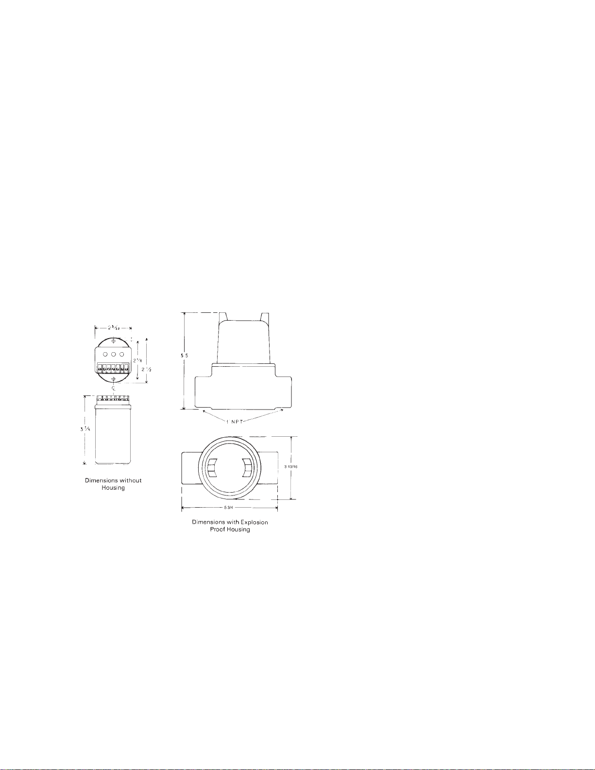
Refer to Figure 2-1 for outline dimensions. Drill appropriate
mounting holes as required.
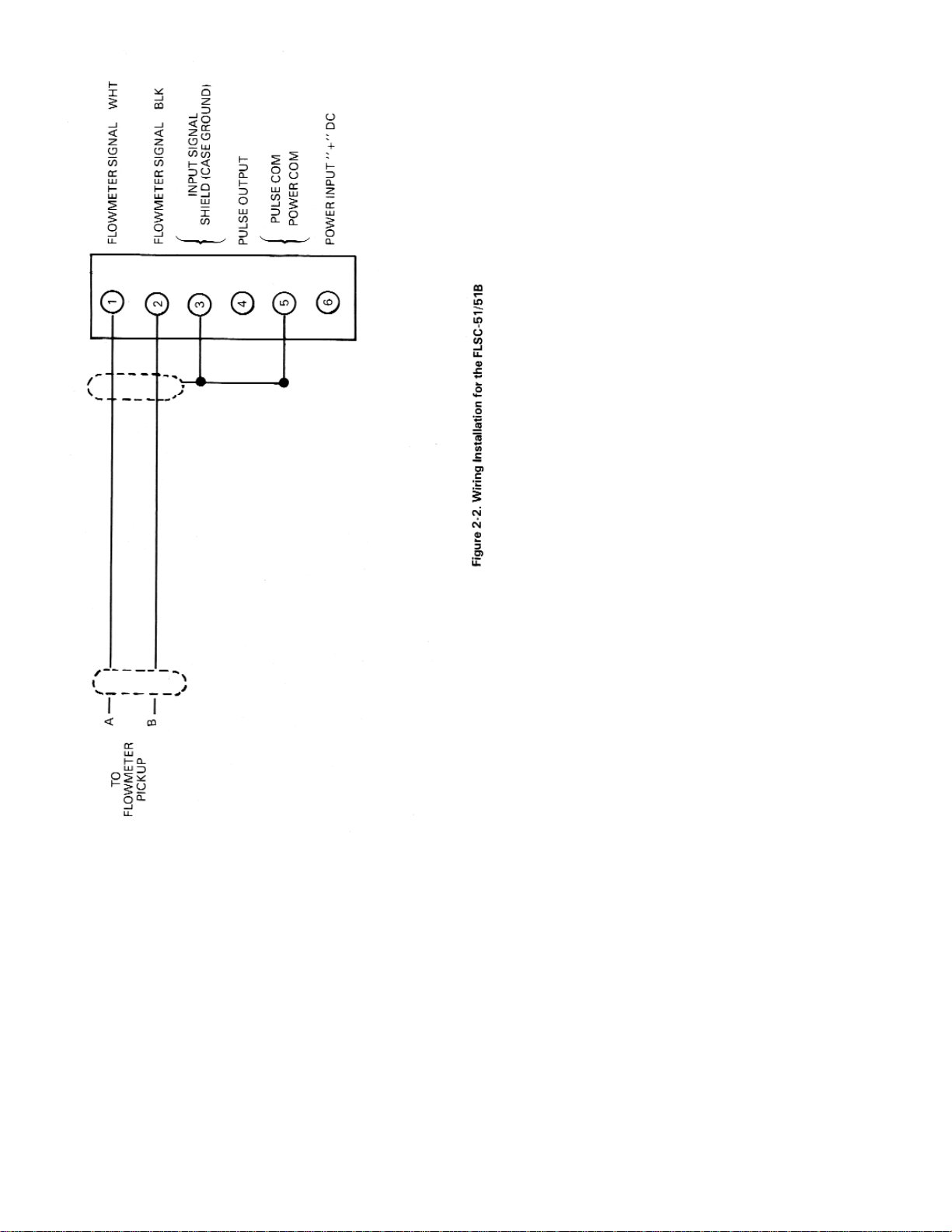
Refer to Figure 2-2, wiring installation, for appropriate terminals
for interconnections. The signal leads from the turbine should be
shielded whenever the FLSC-51/51B is not integrally mounted.
Ground shield on one end only If desired,use solder lug
provided on ground stud. Connections to the terminal block
should be carefully dressed to avoid having bare wires
extending pass the screw clamp on the terminal block. This is
particularly important for units mounted within the explosion
proof enclosure. Wires should be neatly dressed near bottom of
enclosure to assure wiring will not become fouled when cover is
installed. Connect two conductor shielded cable f rom
flowmeter. Connect shield to FLSC-51/51B only.
Unit is powered by a DC voltage, 8-35 Vdc. Connect power as
illustrated in Figure 2-2.
Figure 2-1. Outline and
Intallation Dimensions
Page 62
57
Page 63

58
SECTION 3 OPERATION
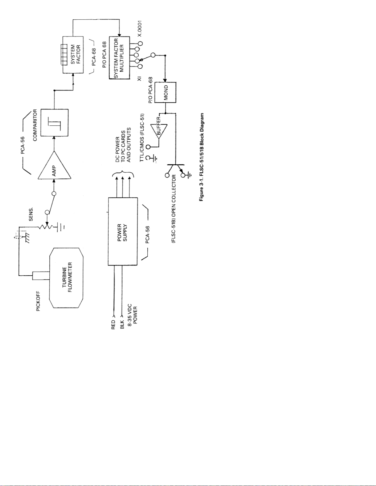
3.1 PRINCIPLE OF OPERATION
A simplified block diagram of the FLSC-51151B is shown in Figure
3-1. Key functional blocks as well as information flow are
designated. The basic operation of the system is as follows.
The frequency signal from the turbine flowmeter is connected to
the FLSC-51/51B with a twisted pair shielded cable. The signal
enters through the SENSITIVITY control which is used to reject
unwanted noise by raising the trigger threshold above the
background noise present.
The low level flowmeter signal is then passed through a signal
conditioning chain where it is filtered, amplified and shaped into a
train of digital pulses whose frequency is related to the volume
flow rate and where each pulse represents a discrete volume of
fluid.
The linear signal in the form of a pulse train is then passed to the
System Factor which scales the signal for totalization.
The pulse scaling circuitry composing the System Factor
affectively multiplies the pulse rate by a number set into the digital
thumbwheel switch array on the PCA-62 printed circuit card.
At the output of the System Factor, each pulse represents a
decimal multiple of the desired flow measurement units.
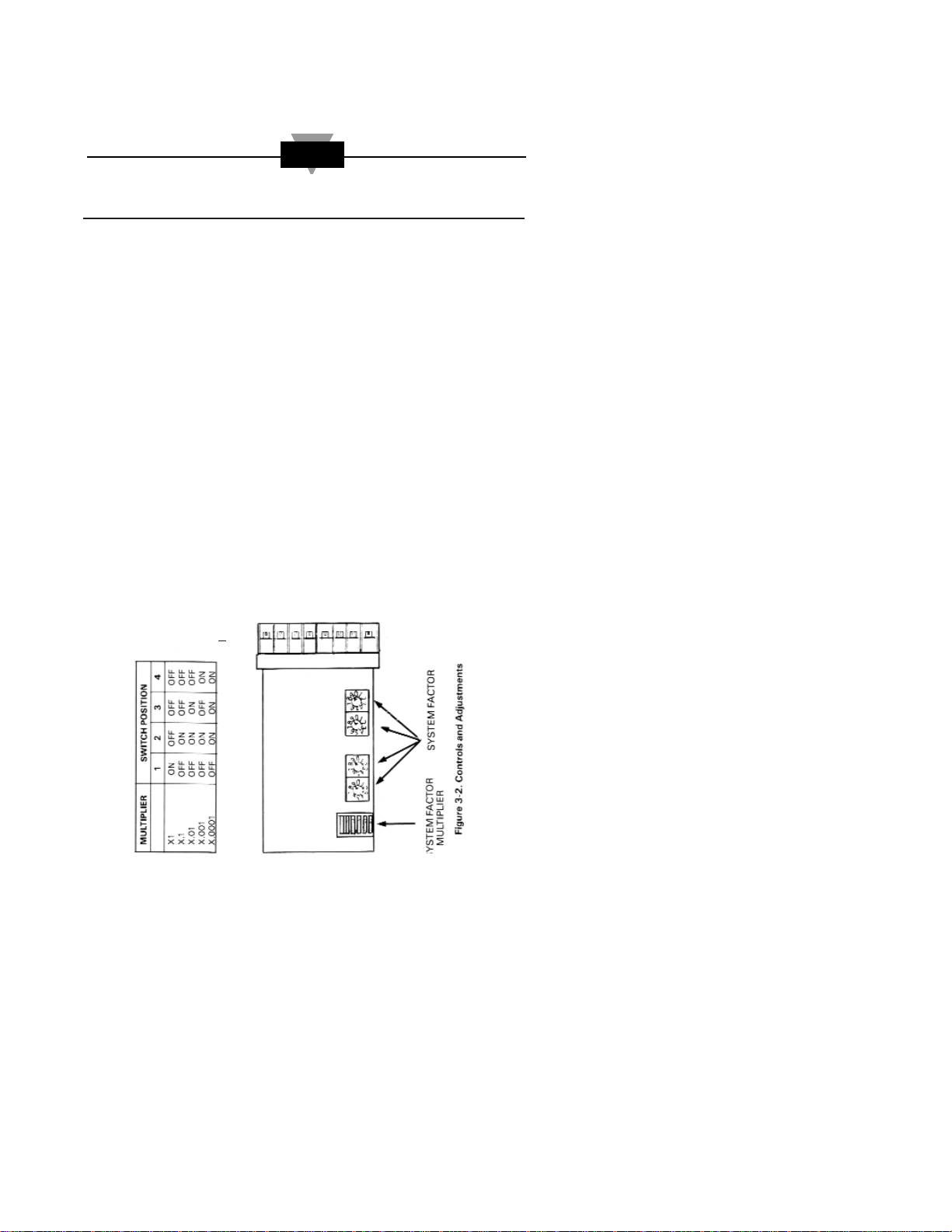
The pulse train is fed to the System Factor Multiplier which
effectively multiplies the pulse rate by either 1, .1, .01, .001 or .0001
depending on the position selected on the corresponding switch.
At the output of the System Factor Multiplier block, each pulse
represents one unit of flow in the desired measurement units.
The pulse train is then passed through an output drive stage
which is connected to a host system. A pulse is output each time a
discrete volume of fluid, represented in the desired units, passes
through the flowmeter.
3.2 START-UP OPERATION
Perform any purging of piping with spool piece in place. Once
completed, install the flowmeter and connect cabling to pickup
coil
With the Flow Measurement System properly installed and
calibrated, verify the following performance checks before
placing the system into active service.
The signal conditioner is normally shipped with the
SENSITIVITY pot fully counterclockwise. At start-up, turn this
pot gradually clockwise until input signal is sensed.
Page 64
59
Page 65
60
With the power to the unit, and NO flow through the
flowmeter, the pulse output frequency should be 0. If the output
pulse frequency is greater than 0, input noise may be present.
Slowly turn the SENSITIVITY threshold control
counterclockwise until a pulse rate of 0 is indicated.
Turning the SENSITIVITY control fully counterclockwise will render the unit
inoperative,
3.3 GENERAL OPERATION
Apply power to the unit (8-35 Vdc).
The FLSC-51/51B will output the desired units of pulses per
unit volume established by the calibration setup procedure (see
Section 4).
Pulses output begins automatically when flow through the
flowmeter commences.
3.4 CONTROLS AND ADJUSTMENTS (See Figure3-2.)
SENSITIVITY A multiple turn control used to set the
trigger level above the noise level.
SYSTEM FACTOR A thumbwheel switch array composed
IS. F.) of four switches which are used to set
the desired scaling factor (.0000 to
.9999). Used in conjunction with the
System Factor Multiplier.
SYSTEM FACTOR A dip switch used to enter the desired
MULTIPLIER system factor multiplier (1, .1, .01,
(S. F. M.) .001, .0001). Used in conjunction with
the system factor.
(S.F.) x (S F M ) -= 1
K
1
NOTE
Page 66

61
SECTION 4 CALIBRATION OF THE FLSC-51/61B
4.1 INTRODUCTION
The FLSC-51/51B Flowmeter Signal
Conditioning/Interface/Subsystem has a special feature which
allows the user to scale the flow information into the desired
units of measurement. This feature is termed the SYSTEM
FACTOR and is composed of two arrays of switches (the
SYSTEM FACTOR thumbwheel switch and the SYSTEM
FACTOR MULTIPLIER dip switch).
By utilizing the SYSTEM FACTOR, the total flow may be
indicated as pulse outputs in gallons, pints, liters, barrels, cc’s.
4.2 PROCEDURE
Begin by obtaining a copy of the calibration sheet for the
flowmeter to be used with the FLSC-51/51B, Obtain the desired
units of measurement from the project supervisor or equipment
specification.
From the calibration sheet for the flowmeter (supplied with
flowmeter obtain the MEAN K FACTOR in cycles/gallon,
designate this as the K FACTOR.
Finally, note the maximum f low rate in desired units as R
(MAX) in unit volumes/minute. The value of R (MAX) should
be less than the maximum count speed for the host system.
Compute the equivalent number of pulses per desired
measurement unit, designed K, from the K FACTOR for the
flowmeter and the conversion factor relating the gallons per
user’s desired measurement units, This may be done with the
following equation and the aid of a conversion chart.
K’ = K FACTOR x CF
WHERE
CF is the conversion factor equal to the ratio of the number of
gallons per user chosen volume unit.
Example:
Given: 200 pulses/gallon = K FACTOR
Desired units of measurement = Liters
Obtain: Conversion Factor CF = .2642 gallons/liter
from Table
Calculate: K1= 200 x .2642
= 52.84 Pulses
Liter
Page 67

62
The SYSTEM FACTOR should be programmed with the largest
number of significant figures which maybe represented within
the limitations of the switch array.
SECTION 5 TROUBLESHOOTING
In case of an inoperable or malfunctioning system the following
procedures can be used to isolate the faulty wiring, printed
circuit boards and/or alternate causes. The majority of repairs
can be made in the field thereby reducing the time a unit is out
of service.
The necessary documentation is contained within this manual
with the exception of the calibration data sheet for the turbine
flowmeter. This calibration is supplied with the turbine
flowmeter.
Factory consultation is available to assist in diagnosing
problems. Note that in some cases factory repairs can be
performed more easily than can be accomplished in the field.
Failure conditions are listed and the possible corrective actions
given to eliminate the observed problem.
Proper operation of the FLSC-51/51B can be assumed when
with power applied to the unit, the pulse output produces a
pulse train of the desired amplitude when flow through the flow
transducer occurs.
PROBLEM POSSIBLE CAUSE CORRECTIVE
ACTION
Unit does not Power Loss Check interproduce pulse connecting wiring and
output with and host system.
Bad pickup coil or Check coil and cable
signal cable for continuity and
leakage.
Replace if bad.
Fouled or damaged Remove and clean per
turbine flowmeter manufacturers recom-
mended procedure.
Bad FLSC-51/51B Repair or replace with
new unit.
Sensitivity Pot Readjust Sensitivity
turned too far control.
clockwise.
Page 68

63
PROBLEM POSSIBLE CAUSE CORRECTIVE
ACTION
Unit produces Input noise Turn Sensitivity Pot
pulse with no clockwise until false
flow out output stops.
Bad pickup coil or Check coil and cable
open signal cable for continuity and
leakage.
Replace if bad.
Extreme shock or Dampen or relocate
vibration of piping. flowmeter.
Power supply Check and repair as
malfunction required.
Bad FLSC-51/51B Repair or replace with
new unit
SECTION 6 SPECIFICATIONS
INPUT Input filtered, RF and Bandpass filtered adjustable
trigger level; Input impedance - 10 mV RMS, 10-1000 Hz; Over
voltage capability 120 V RMS (absolute)
PULSE SCALING: System Factor and System Factor Multiplier
provide a cascaded chain of two scaling factors. The system
factor provides for scaling factors of .0000 to.9999 with four
thumbwheel switches. The system f actor multiplier provides
additional scaling factors of 1, .1, .01, .001, .0001.
OUTPUT CHARACTERISTICS: Pulse Duration - .2 ms (FLSC-
51); 50 ms (FLSC-51B)
Open Collector Type FLSC-51B) - 2N6660 V max 60 Vdc
Absolute Max. I max 1.2 Adc Absolute Max. CMOS/TTL (FLSC-
61) Logic 1, 2.4 Vdc @ -.800 mA Logic 0, 0.4 Vdc @ 2.6 mA
High Level Pulse Output may be provided with a pullup
resistor to the input power supply.
INPUT POWER: 8-35 Vdc @ 10 mA; Reverse Polarity Protected;
Input Filtered
ENVIRONMENTAL: Operating Temperature 0° to 70°C (STD);
Storage Temperature -65° to 150°C
ELECTRICAL HOUSING: Class 1, Group D
Class 11 Group E, F, G
Class III
Page 69
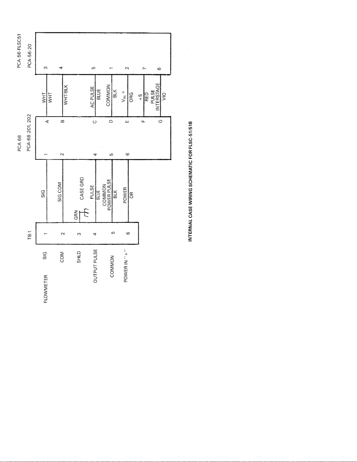
64
Page 70

65
NOTES:
Page 71

66
NOTES:
Page 72

Where Do I Find Everything I Need for
Process Measurement and Control?
OMEGA…Of Course!
Shop online at www.omega.com
TEMPERATURE
MU
Thermocouple, RTD & Thermistor Probes, Connectors, Panels &
Assemblies
MU
Wire: Thermocouple, RTD & Thermistor
MU
Calibrators & Ice Point References
MU
Recorders, Controllers & Process Monitors
MU
Infrared Pyrometers
PRESSURE, STRAIN AND FORCE
MU
Transducers & Strain Gages
MU
Load Cells & Pressure Gages
MU
Displacement Transducers
MU
Instrumentation & Accessories
FLOW/LEVEL
MU
Rotameters, Gas Mass Flowmeters & Flow Computers
MU
Air Velocity Indicators
MU
Turbine/Paddlewheel Systems
MU
Totalizers & Batch Controllers
pH/CONDUCTIVITY
MU
pH Electrodes, Testers & Accessories
MU
Benchtop/Laboratory Meters
MU
Controllers, Calibrators, Simulators & Pumps
MU
Industrial pH & Conductivity Equipment
DATA ACQUISITION
MU
Data Acquisition & Engineering Software
MU
Communications-Based Acquisition Systems
MU
Plug-in Cards for Apple, IBM & Compatibles
MU
Datalogging Systems
MU
Recorders, Printers & Plotters
HEATERS
MU
Heating Cable
MU
Cartridge & Strip Heaters
MU
Immersion & Band Heaters
MU
Flexible Heaters
MU
Laboratory Heaters
ENVIRONMENTAL
MONITORING AND CONTROL
MU
Metering & Control Instrumentation
MU
Refractometers
MU
Pumps & Tubing
MU
Air, Soil & Water Monitors
MU
Industrial Water & Wastewater Treatment
MU
pH, Conductivity & Dissolved Oxygen Instruments
M0390/0301
 Loading...