

Page 1
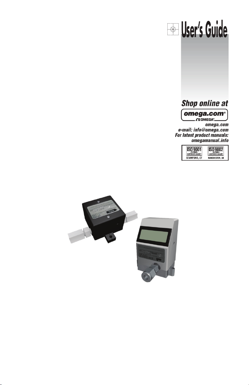
FLR 1000/1000BR/1000ST Series
Flow Sensors & Meters For Liquids
Page 2
Page 3

READ THIS MANUAL COMPLETELY BEFORE ATTEMPTING TO CONNECT
OR OPERATE YOUR FLOW SENSOR. FAILURE TO DO SO MAY RESULT
IN INJURY TO YOU OR DAMAGE TO THE FLOW SENSOR.
TABLE OF CONTENTS
A. Introduction ....................................................................................... 4
1. Unpacking ............................................................................................... 4
2. Product Overview And Principle Of Operation ........................................... 4
B. Installation ........................................................................................ 6
1. General Considerations ........................................................................... 6
2. Mounting The Flow Sensor or Flow Meter ................................................. 7
3. Tubing Connections ................................................................................. 8
4. Electrical Connections .............................................................................. 9
a) Overview ........................................................................................... 10
b) Connecting A Cable Assembly ............................................................ 10
c) Electrical Connections – Voltage Output Units ...................................... 11
d) Electrical Connections – Units With Both Voltage & Pulse Outputs ......... 12
e) Electrical Connections – Current Output Units (“I” Suffix) ...................... 13
f) Using a 0-5 V DC Output Power Adapter Package ............................... 14
C. Operation ....................................................................................... 15
1. Start-Up ................................................................................................. 15
2. Entrapped Air or Gas ............................................................................. 15
3. Flow Readings ....................................................................................... 15
a) 0-5 V DC Analog Outputs .................................................................. 16
b) Pulse Outputs ..................................................................................... 16
c) 4-20mA Outputs ................................................................................ 17
d) Units with an Integral Display .............................................................. 17
4. Operating at Flow Rates Outside the Calibrated Flow Range .................... 18
a) Flows Above the Maximum Ra ted Flow ................................................ 18
b) Flows Below the Maximum Rated Flow ................................................ 18
5. Zero Adjustments ................................................................................... 18
6. Recalibration .......................................................................................... 18
7. Calibrating Units for different Liquids ...................................................... 21
D. Maintenance And Product Care ......................................................... 21
1. General ................................................................................................. 21
2. Cleaning and Flushing ........................................................................... 22
3. Returning Units For Repair Or Recalibration ............................................ 22
E. Specifications ................................................................................... 23
F. Dimensions...................................................................................... 25
G. Connector Pin And Wire Color Cross Reference ................................... 30
H. Trouble Shooting Guide .................................................................... 31
Page 4
A. Introduction
1. Unpacking
All units are suitably packaged to prevent damage during shipping. If
external damage is noted upon receipt of the package, please contact
Omega Engineering immediately.
Open the package from the top, taking care not to cut too deeply into the
package. Remove all the documentation and contents. Take care to remove
all the items and check them against the packing slip. The products should
also be checked for any concealed shipping damage. If any shortages or
damage is noted, please contact the shipping company and/or Omega
Engineering to resolve the problem.
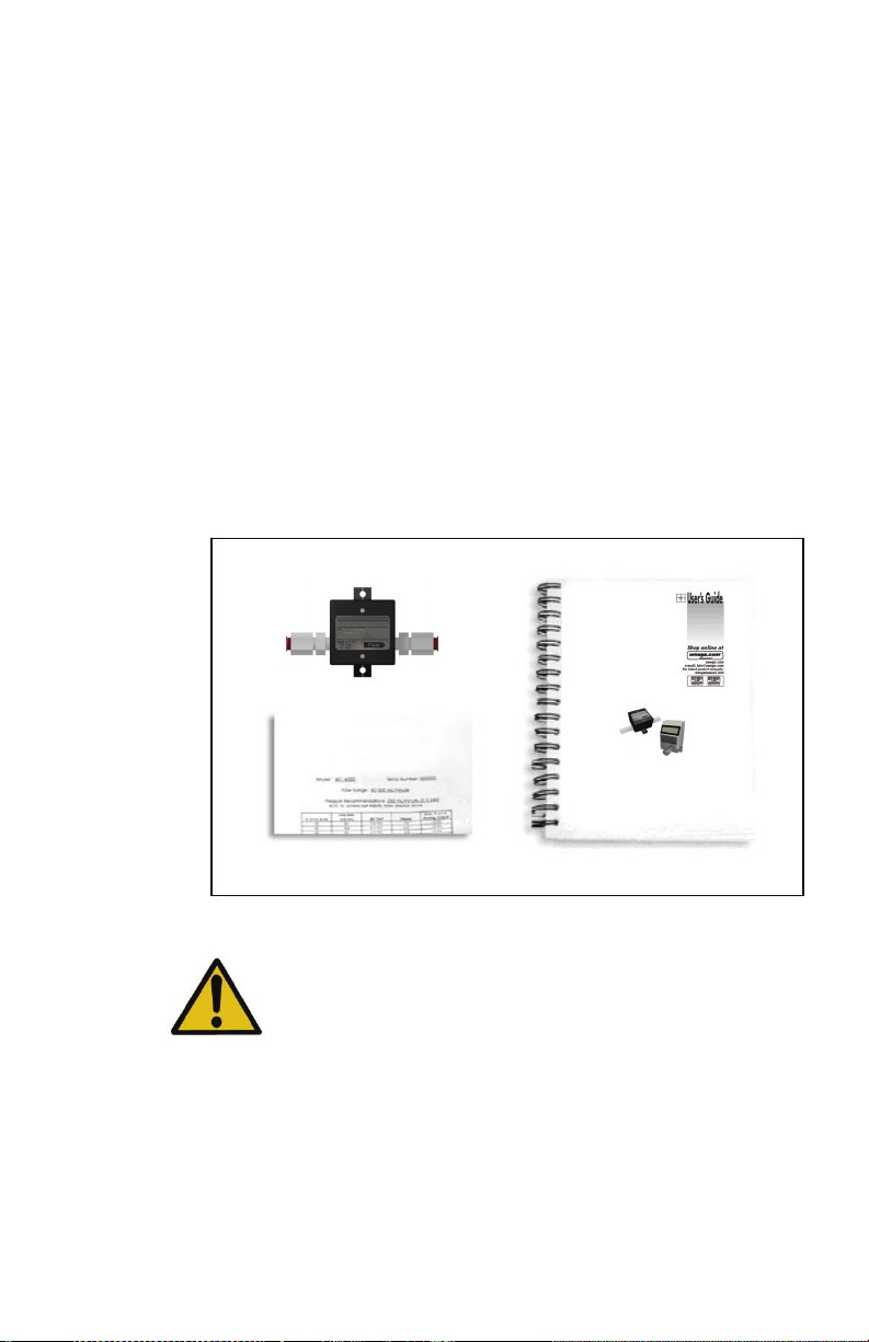
Sensor, Calibration Certificate & Instruction Manual
(Model FLR 1000 shown, other models similar).
Typical Contents of Box:
FLR 3100/3100BR/3100ST
CAUTION: Take care not to
drop
your sensor or subject it to
sudden impact. Read the installation section of this manual before
providing power or tubing connections to the unit. Any damage
caused by improper installation or careless handling will not be
repaired under warranty (see limited warranty on page 33 for
more details).
2. Product Overview and Principle of Operation
The FLR 1000 series of flow meters and sensors for liquids from Omega
Engineering are capable of measuring flows as low as 13-100 ml/min or as
high as 1.0-10.0 l/min. Highly repeatable results are achieved using a
patented Pelton Turbine Wheel flow sensor design. This proven design
pg. 4 of 34
Series
Page 5
minimizes zero drift while maintaining fast response and linear outputs with
virtually no maintenance.
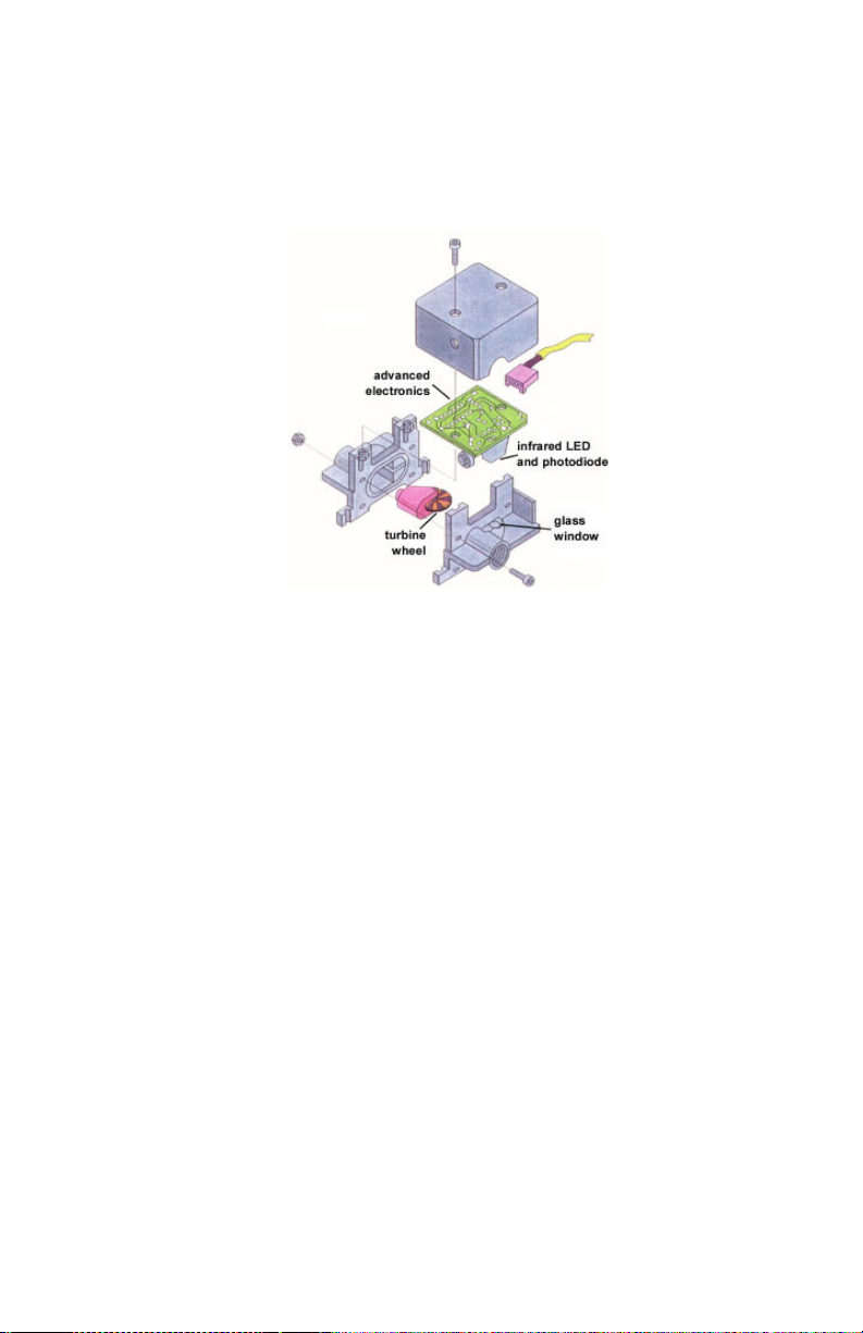
Flow is measured using a miniature turbine wheel similar in size to a U.S.
dime (16 mm diameter, 0.75 mm thick). The micro-turbine wheel is
supported on a very small sapphire shaft that is held in position by two
sapphire bearings. The micro-turbine assembly is so light that it virtually
floats in the liquid. This relieves force on the bearings and almost eliminates
wear.
As flow passes through the sensor, a precision machined nozzle directs the
fluid onto the very small teeth of the micro-turbine wheel. This causes the
wheel to spin at a speed proportional to the flow rate.
The micro-turbine wheel has alternating white and black sections evenly
spaced on one side of the wheel. An infrared light beam is directed onto the
wheel. As the wheel rotates the infrared beam is reflected off each white
section. The reflected beam is detected by a phototransistor that converts the
reflections into electrical pulses. As the wheel spins faster the pulse rate
increases. Processing circuitry provides analog and/or pulse output that are
linearly proportional to the flow rate
When the wheel stops (under zero flow conditions), no pulses are
generated. Consequently, zero drift is not possible and zero adjustments are
never required.
Every unit is supplied with a calibration certificate detailing the results
obtained during calibration. Units are calibrated using deionized water as
the reference media. Flowing liquids with different specific gravities or
viscosities may affect the calibration.
pg. 5 of 34
Page 6
B. Installation
CAUTION: Do not flow any gas through a liquid flow sensor.
This may damage the micro-turbine assembly and void the
warranty. Do not exceed the pressure, temperature or power
operating ranges detailed in the SPECIFICATIONS section of this
manual. Omega Engineering shall not be liable for any damage
or injury caused by incorrect operation of their products.
1. General Considerations
It is recommended that a safety shut-off valve be installed upstream of
(before) the sensor.
All wetted parts should be checked for compatibility with the liquid to be
used. If there are any incompatibilities e.g. highly corrosive liquid, then the
unit may be damaged or fail prematurely. Such damage will not be
repaired under warranty.
Units should be installed in a clean, dry environment with an ambient
temperature that is as stable as possible. Avoid areas with strong magnetic
fields, strong air flows or excessive vibration.
If the liquid to be used may contain particles larger than 25 microns then a
filter (25 microns or less) should be installed upstream of (before) the unit.
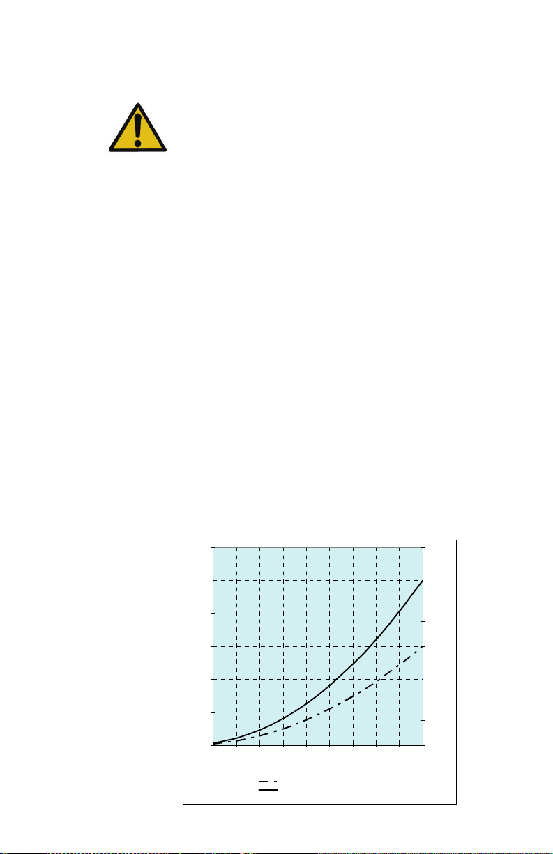
The required differential press (or pressure drop across the unit) decreases
exponentially with decreases in flow rate.
Pressure Drop vs. Percentage of the Full Scale
Rated Flow (may vary ±10% of indicated psid)
12
0.8
10
8
6
Delta P ps id
4
2
0
10 20 30 40 50 60 70 80 90 100
% of rated flow
100-1000 ml/min Un its
All Oth er R ang es
0.7
0.6
0.5
0.4
Delta P Bar
0.3
0.2
0.1
0
pg. 6 of 34
Page 7

To calculate the pressure drop at a certain flow rate use the formula
PD = (YourFlow / MaxFlow)2 x PDmax
PD = Pressure drop at YourFlow.
YourFLow = flow rate (ml/min or l/min)
MaxFlow = 100% rated flow for the sensor (in same units as YourFlow)
PD
max = Pressure drop at 100% rated flow (see chart above)
If the pressure available for the flow sensor is BELOW the pressure drop at
the required flow then flow through the unit will not be possible.
For example: You have a sensor with a 50-500ml/min flow range and want
to know the pressure drop (or minimum differential pressure required) at
300ml/min. According to the chart above, the pressure drop at 100% of
flow is approx 10psi. Using the formula above:
PD = (300 / 500)
Therefore, at 300ml/min the minimum required differential pressure for this
unit is 3.6 psid. This means that if the available pressure is below 3.6psid
then flow through the unit may not be possible.
Pressure drop through a system is cumulative. If the total pressure drop
across all the components in a system exceeds the minimum pressure
available then flow will not be possible.
For example: A system has a pressure of 30-40psi. There are several
components and the sum of their pressure drops at the required flow rate is
32psid. If the system is operating at 30psi flow would not be possible as the
total of the pressure drops would be greater than the pressure available.
The system will only operate if the system pressure is above 32psi.
If there is any possibility that there may be bubbles or entrapped gas in the
system then the outlet tubing should be elevated above the inlet port. This
will enable any gas that may become entrapped in the unit to escape (see
section C2 for details of how to remove entrapped air or gas).
2. Mounting the Flow Sensor or Flow Meter
The Omega Engineering FLR 1000 Series units have no particular
installation requirements so may be mounted in any convenient position.
It is recommended that units be fixed to a suitable substrate with #4 screws
using the two mounting holes provided.
2
x 10 = 3.6 psid
pg. 7 of 34
Page 8
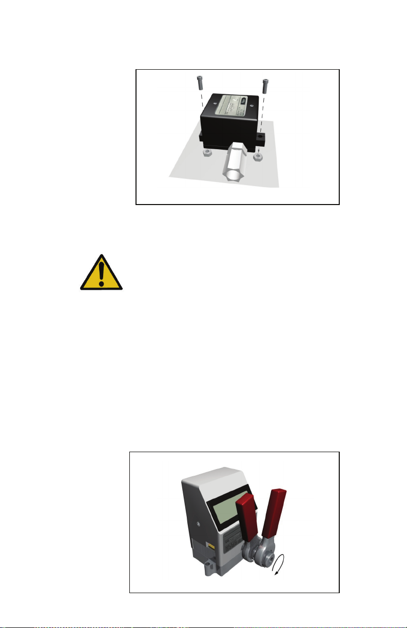
(mounting hardware not included with sensor)
Mounting The Sensor
3. Tubing Connections
CAUTION: DO NOT FLOW ANY GAS THROUGH A
LIQUID FLOW SENSOR OR FLOW METER. THIS WILL
DAMAGE THE MICRO-TURBINE ASSEMBLY AND VOID
THE WARRANTY.
All tubing must be clean and without crimps, burrs or scratches.
Only use the fittings factory installed on the unit. If the fittings are removed
the calibration of the unit may be affected and leaking may occur. If
different fittings are required please contact the Omega Engineering Service
Department for assistance.
When connecting the sensor to the tubing a wrench should be used to stop
the fitting rotating in the sensor body. Take care not to over tighten the
fittings or leaking may occur.
Connecting and tightening the Fittings
(FLR 1000-ST-D shown, other models similar)
pg. 8 of 34
Page 9
CAUTION: DO NOT over tighten the fittings into the sensor
body. Excessive force may damage the sensor body and will
NOT be repaired under warranty.
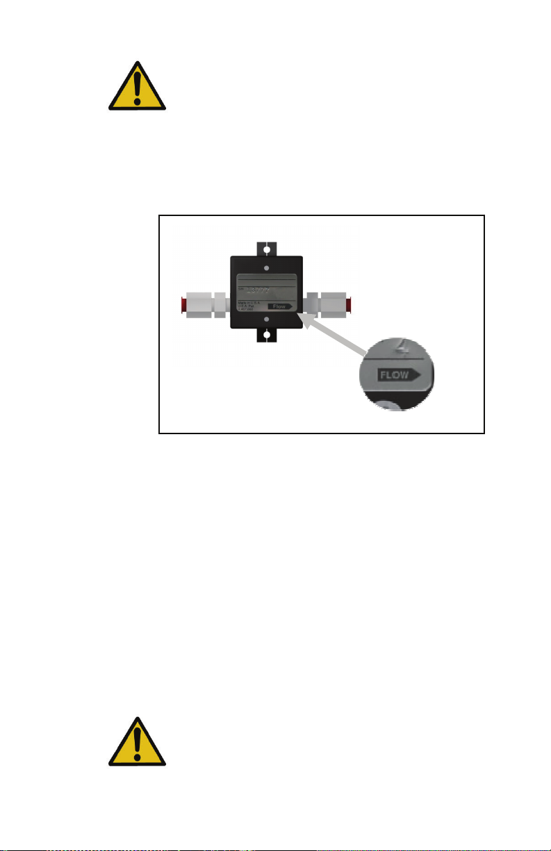
The flow direction for the sensor is clearly marked on the label. Do not
reverse the flow direction or the unit will not function.
Close Up of Label Showing Flow Direction
(FLR 1000 shown, other models similar)
For the best results precautions should be taken to minimize the amount of
turbulence in the flow stream. Avoid valves, fittings, curves in the tube,
changes in the internal diameter or any other restrictions close to the inlet of
the sensor. The tubing ID should be as large as possible and preferably not
smaller than the ID of the fittings installed on the sensor.
For 0.2-2.0 L/min units a 10 cm straight length of tube before the sensor is
recommended. For higher flow range units (0.5-5.0 L/min and 1.0-10.0
L/min), a 20 cm straight length of tubing before the sensor is recommended.
If this is not possible it is recommended that straight lengths between all
connections on the inlet side of the sensor are as long as possible and 90
degree fittings (with a large enough ID) are used instead of curves in the
tubing.
4. Electrical Connections
CAUTION: Incorrect wiring may cause severe damage to the
unit. Applying an AC voltage (115VAC or 230VAC) directly to
the unit will cause damage. Read the following instructions
carefully before making any connections.
pg. 9 of 34
Page 10
a) Overview
The FLR 1000 series of flow sensors and flow meters provide a 0-5 V DC, or
4-20 mA, or 0-5 V DC and pulse output proportional to the flow rate. This
output may be connected to a display, data acquisition system or
voltmeter/current meter.
The FLR 1000-D, 1000-ST-D and 1000-BR-D series feature an integral
display that provides a local flow reading. These units also have a 0-5 V DC
analog output available. If required, this may be connected to another
display, data acquisition system or voltmeter.
A stable D.C. power supply is required to operate the unit. The voltage and
current requirements depend on the configuration of the unit. Full details
may be found in the Specification section of this manual.
Connecting wires should be as short as possible to avoid voltage drops.
Twisted 2 pair conductor cable should be used if the length of the power
wires is to be longer than 1 meter.
Units are supplied with an integral 4 pin connector. Connections to the unit
are made using a mating cable assembly or power adapter package as
detailed in the following sections (parts 5.b to 5.f of this manual). A
connector pin and wire color cross reference may also be found in
Appendix G (Page 30) of this manual.
b) Connecting the Cable Assembly
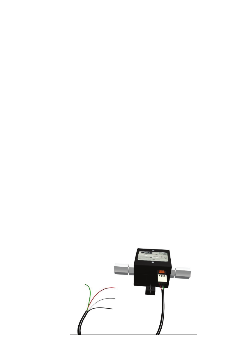
The connector on the end of the cable assembly should be pushed into the
mating socket on the sensor taking care to ensure that it is the correct way
up.
Connecting the Cable Assembly
(FLR 1000 shown, other models similar)
pg. 10 of 34
Page 11
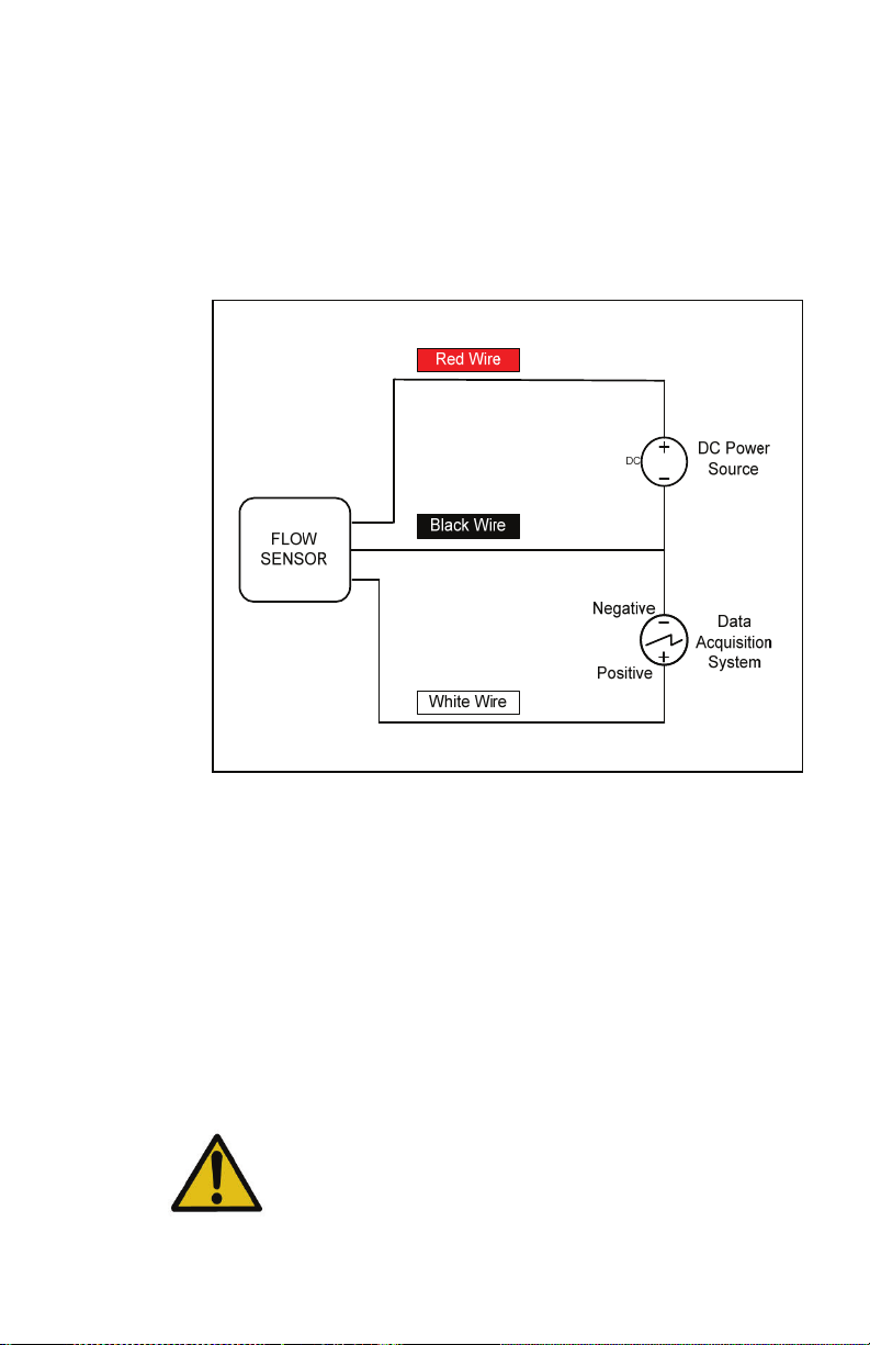
c) Electrical Connections – Voltage Output Units
The cable assembly should be connected to the sensor as detailed in section
5(b) above. Power should not be applied to the sensor until all the
connections have been made and checked. Electrical connections should be
made as follows:
Wiring Schematic For Voltage Output Units.
The RED wire should be connected to the Positive of the power source.
The BLACK wire should be connected to the Negative ( Ground ) of the
power source.
The WHITE wire provides the signal output and should be connected to the
positive terminal of the display, data acquisition system or voltmeter with an
impedance of greater than 2500Ω (Ohms).
The GREEN wire (if present) is NOT used
CAUTION: Avoid high voltage static discharges to any of the
connections. Do not short the input/output signal wires or allow
them to contact the power wires at any time. DAMAGE WILL
RESULT!
pg. 11 of 34
Page 12
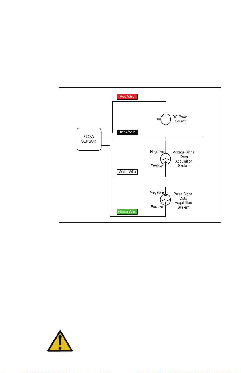
d) Electrical Connections –Units with Both Voltage and Pulse
Outputs
The cable assembly should be connected to the sensor as detailed in section
5(b) above. Power should not be applied to the sensor until all the
connections have been made and checked. Electrical connections should be
made as follows:
Wiring Schematic For Voltage and Pulse Output.
The RED wire should be connected to the Positive of the power source.
The BLACK wire should be connected to the Negative ( Ground ) of the
power source.
The WHITE wire provides the signal output and should be connected to the
positive terminal of the display, data acquisition system or voltmeter with an
impedance of greater than 2500Ω (Ohms).
The GREEN wire (“P” suffix only) is the pulse output and should be
connected to the Positive terminal of the data acquisition system with an
impedance of greater than 10KΩ (Ohms).
The PULSE and VOLTAGE output may be monitored simultaneously.
CAUTION: Avoid high voltage static discharges to any of the
connections. Do not short the input/output signal wires or allow
them to contact the power wires at any time. DAMAGE WILL
RESULT!
pg. 12 of 34
Page 13
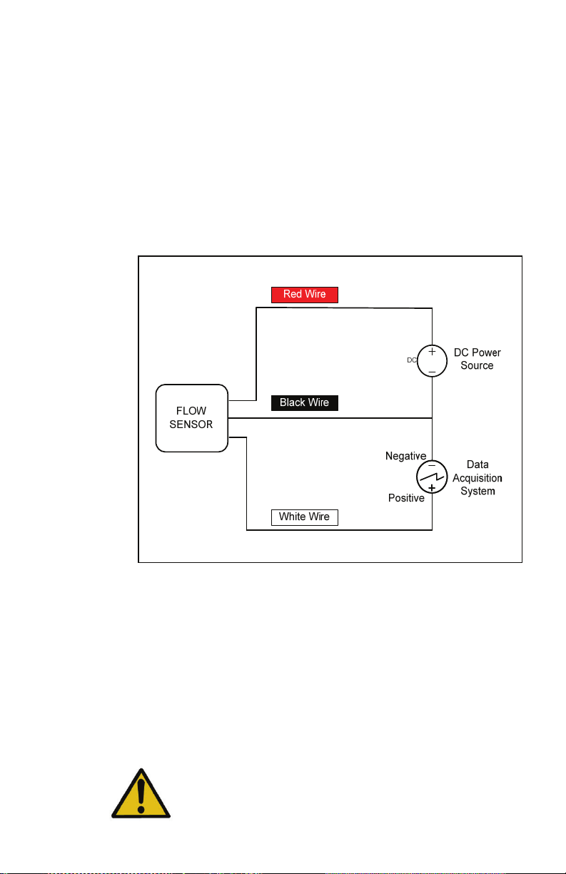
e) Electrical Connections – Current Output Units (“I” Suffix)
The FLR 1000–ST-I provides a 4-20mA active current output proportional to
the flow rate.
The cable assembly should be connected to the sensor as detailed in section
5(b) above. Power should not be applied to the sensor until all the
connections have been made and checked. Electrical connections should be
made as follows:
Wiring Schematic For Current Ouput Units (“I” suffix only).
The RED wire should be connected to the Positive of the power source.
The BLACK wire should be connected to the Negative ( Ground ) of the
power source.
The WHITE wire provides the signal output (active current) and should be
connected to the positive terminal of the display, data acquisition system or
current meter with an impedance of 0 - 500Ω (Ohms).
The GREEN wire is NOT used.
CAUTION: Avoid high voltage static discharges to any of the
connections. Do not short the input/output signal wires or allow
them to contact the power wires at any time. DAMAGE WILL
RESULT!
pg. 13 of 34
Page 14
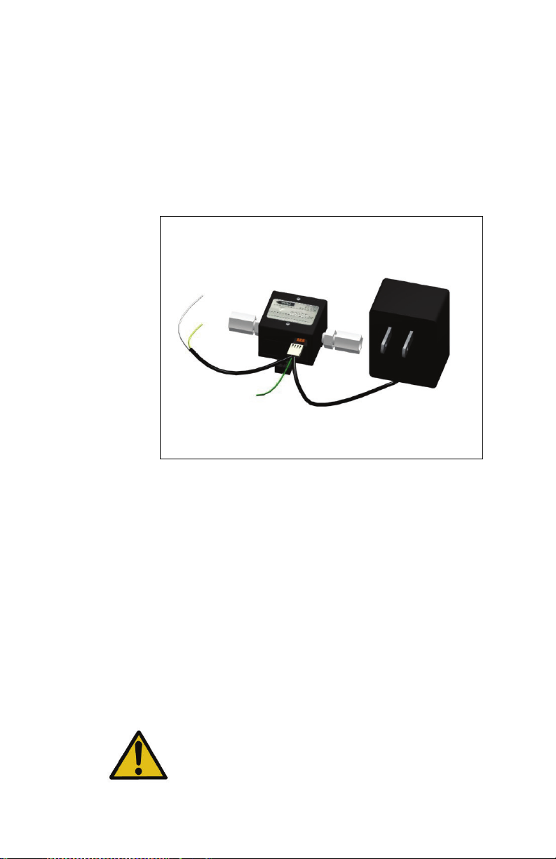
f) Using a 0-5VDC Output Power Adapter Package
An optional 0-5 V DC Output Power Adapter Package is available for use
with the FLR 1000 series (not the FLR 1000-ST-I). This consists of a power
source (115VAC or 230VAC) and cable assembly with pig-tail (soldered
wire) ends for the signal output. This should be assembled as shown in the
following diagram.
Connecting the Power Adapter to the Flow Sensor
(FLR 1000 shown, other models similar)
Electrical connections to the cable assembly should be made as follows:
YELLOW WIRE: This provides the 0-5 V DC signal output and should be
connected to the positive terminal of the display, data acquisition system or
voltmeter with an impedance of greater than 2500Ω (Ohms).
GREEN WIRE: For Pulse output units (“P” suffix only) the green wire
provides the pulse output and should be connected to the positive terminal
of the data acquisition system with an impedance of greater than 10KΩ
(Ohms).
WHITE WIRE: This is the signal negative and should be connected to the
negative (ground) terminal of the voltmeter, display or data acquisition
system.
CAUTION: Avoid high voltage static discharges to any of the
connections. Do not short the output signal wires or allow them to
contact the power wires at any time. DAMAGE WILL RESULT!
pg. 14 of 34
Page 15
C. Operation
CAUTION: USE WITH LIQUIDS ONLY. FLOWING GAS
OR AIR THROUGH YOUR LIQUID FLOW SENSOR WILL
DAMAGE THE MICRO-TURBINE ASSEMBLY. THIS TYPE
OF DAMAGE WILL NOT BE REPAIRED UNDER
WARRANTY.
1. Start Up
Before applying power to the unit check all tubing and electrical
connections. Once correct installation is verified switch on the power.
2. Entrapped Air or Gas
There may be a lot of air or gas trapped in your sensor after installation.
This will usually escape the unit when flow (within the range of the unit) is
first started.
CAUTION: The system should be primed with liquid and flow
started gradually. This will prevent trapped air or gas from being
forced through the sensor at a high velocity that may damage the
sensor.
If gas remains entrapped in the unit it may be necessary to elevate the outlet
tubing above the inlet of the unit. This should enable the trapped gas to
escape the unit. The unit may be returned to its original position once all the
gas has escaped.
If elevating the outlet tubing does not work, block or pinch the outlet tube
whilst there is flow in the system. After approximately 5 seconds, release the
restriction to allow normal flow. Doing this will build up pressure in the flow
path that when released will help remove the entrapped gas. Repeat this
until the entrapped gas is removed form the unit.
3. Flow Readings
The FLR 1000 Series provide a 0-5 V DC, or 4-20 mA (I suffix), or 0-5 V DC
and pulse output (P suffix) proportional to the flow rate. The type of output
signal is detailed by the part number reference and on the calibration
certificate.
The FLR 1000-D, FLR 1000-BR-D and FLR 1000-ST-D series features an
integral display that provides a local flow reading and a 0-5 V DC analog
output.
pg. 15 of 34
Page 16

Each unit is factory calibrated for a specific flow range. The flow range is
shown on the unit’s label and calibration certificate. Units are calibrated
using deionized water as the reference media.
a) 0-5VDC Analog Outputs
By monitoring the voltage output signal it is possible to determine the flow
rate of the liquid. Units are configured so that an output signal of 5.0 V DC
is provided when the maximum flow (i.e. Full Scale flow) is passing through
the unit. The output signal is linear and scaleable enabling calculation of
flow rates within the sensor’s range. For example:
For a flow range of 50-500ml/min:
At 500ml/min the output signal would be 5 V DC
If the output signal were 3.5 V DC then the flow rate would be:
(500 ÷ 5) × 3.5 = 350ml/min
If the maximum flow rate is exceeded non-linear and inaccurate readings
will result.
b) Pulse Outputs
By monitoring the Pulse output frequency it is possible to determine the flow
rate of the liquid. The pulse frequency for maximum flow through the unit
(i.e. full scale flow) is detailed on the calibration certificate. This differs from
unit to unit. This output is approximately linear and scaleable within the
sensor’s range. For example:
For a flow range of 1.0-10.0l/min:
The calibration certificate gives the following:
At 10.0l/min the pulse output signal is 312Hz
At 5.0l/min the pulse output signal is 150Hz
At 2.0l/min the pulse output signal is 58Hz
If the output signal were 120Hz then the flow rate would be:
(5.0 ÷ 150) × 120 = 4.0 l/min (using the closest calibration point)
pg. 16 of 34
Page 17
c) 4-20 mA Outputs
By monitoring the current output signal it is possible to determine the flow
rate of the liquid. Units are configured so that an output signal of 20 mA is
provided when the maximum flow (i.e. Full Scale flow) is passing through
the unit. The output signal is 4 mA when there is zero flow through the unit.
The output signal is linear and scaleable enabling calculation of flow rates
within the sensor’s range. For example:
For a flow range of 20-200ml/min:
At 200ml/min the output signal would be 20mA
If the output signal were 9mA then the flow rate would be:
200 ÷ (20-4) × (9-4) = 62.5ml/min
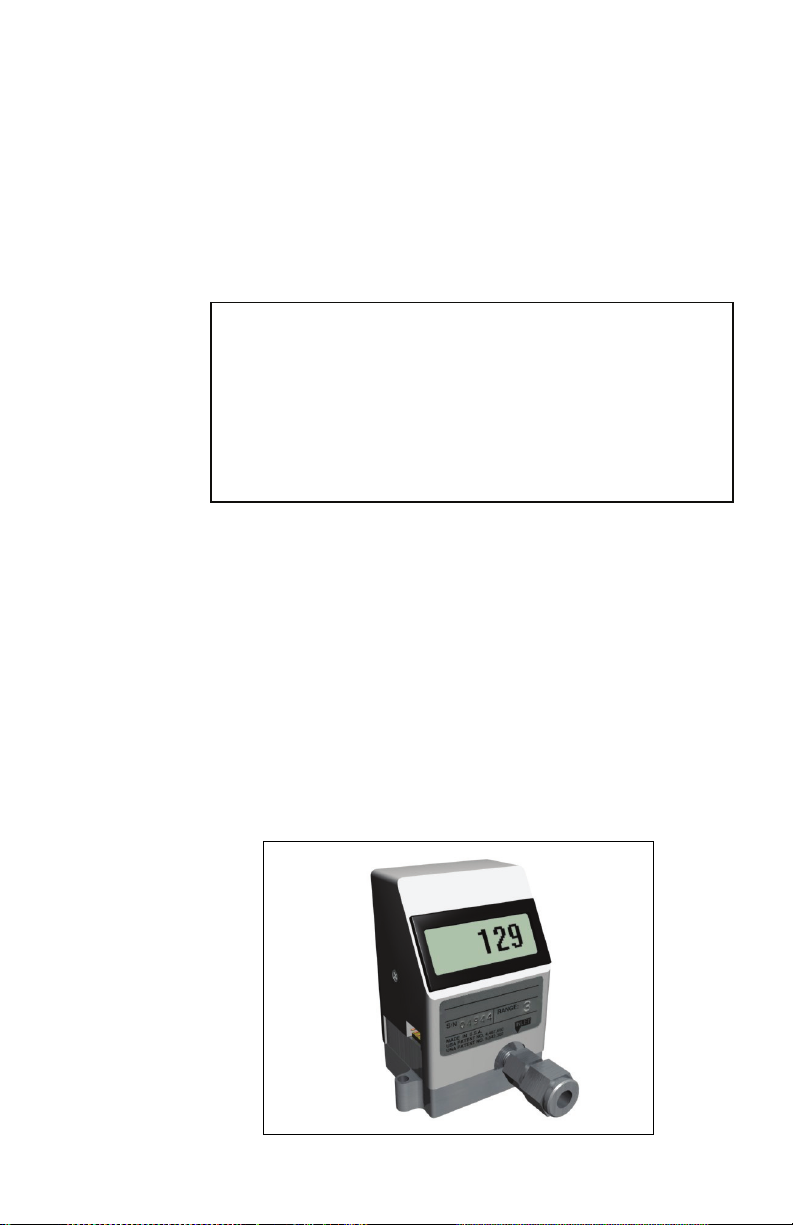
d) Units With an Integral Display
The FLR 1000-D, FLR 1000-BR-D and FLR 1000-ST-D series features an
integral 3 ½ digit LCD display. This is configured to read in ml/min for flow
ranges up to 50-500 ml/min and in l/min for flow ranges of 0.1 – 1.0
L/min. The display will only operate if power is applied to the unit.
Flow readings may be taken directly from the display or by monitoring the
0-5 V DC analog output provided by using a cable assembly or power
adapter package (see above).
(Model FLR1000-ST-D shown, other models with displays similar)
LCD Flow Display
pg. 17 of 34
Page 18

4. Operating at Flow Rates Outside the Calibrated Flow Range
CAUTION: If the flow through the unit exceeds 120% of the
maximum rated (full scale) flow the unit may be damaged. This
type of damage will not be repaired under warranty.
Flow measurement is only accurate within the calibrated flow range for the
unit. This is detailed on the calibration certificate. The unit will still operate, to
some degree, outside this flow range.
Results obtained when operating outside the specified range of the unit are
not accurate but may be considered repeatable.
a) Flows Above the Maximum Rated Flow
If the flow rate is above the maximum rated (or full scale) flow, the unit will
still operate and provide an output signal proportional to the flow rate.
Flows must not exceed 120% of the maximum rated flow or the unit may be
damaged.
b) Flows Below the Minimum Rated Flow
Signal outputs may be obtained at flow rates below the minimum specified
for your unit. The amount of flow that may be measured below the minimum
specified varies from unit to unit.
5. Zero Adjustments
It is impossible for there to be any zero drift so zero adjustments are never
required.
6. Recalibration
The calibration of the unit may be easily verified using empirical methods.
It should be noted that the use of empirical methods outside a certified
calibration laboratory is subject to inaccuracy and error. These methods
should only be used to gain an indication of a sensor’s performance. Please
contact the Omega Engineering Service Department if accurate, certified
recalibration is required.
A typical empirical calibration check may be carried out as follows:
Carefully adjust the flow rate so that the maximum output signal is obtained.
With the flow rate constant, liquid flowing through the unit should be
gathered in a container over a timed interval. The total volume flowed over
pg. 18 of 34
Page 19

the timed period should then be measured using a measuring cylinder. The
actual flow rate (in the same units as the flow sensor calibration certificate)
may then be calculated. The actual maximum flow rate should then be
compared to the specified maximum flow rate to determine the error in
calibration. For example:
For a unit with a flow range of 20-200ml/min and a 0-5 V DC
output:
With a constant flow and constant 5 V DC output the actual
volume measured over 30 seconds was 102ml.
Therefore the actual flow rate is:
(102 / 30) x 60 = 204ml/min
The error is therefore 204 – 200 = 4ml/min or 2%
A second empirical check should be made at a flow rate below the
maximum for the unit eg at 50% of full scale. The calculated percentage
error at this flow should then be compared to the error at maximum flow. If
there is a big difference in the percentage errors then the flow signal is no
longer linear and the unit may be damaged (consult the Omega
Engineering Service Department).
Once it has been determined that the linearity is still acceptable and the
error in flow reading at maximum flow has been calculated, there are 3
options:
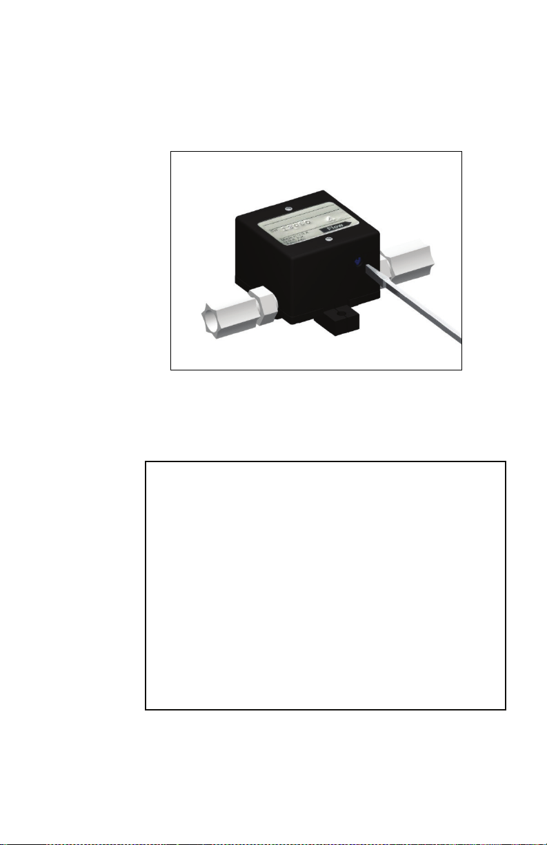
i.) Minor adjustments to actual calibration of the unit may be made by
turning the gain potentiometer on the side of the unit. For example:
For a unit with a flow range of 13-100ml/min and a 0-5 V DC
output:
With a constant flow and constant 5 V DC output the actual volume
measured
over 60 seconds was 103ml.
The correct voltage output for a flow of 103 ml/min is:
(5/100) x 103 = 5.15 V
With the flow at a constant 103 ml/min the gain potentiometer
should be carefully adjusted so that a voltage output reading of
5.15 V is obtained.
pg. 19 of 34
Page 20
If the unit cannot be suitably adjusted please contact the Omega
Engineering Service Department. Pulse outputs are not adjustable.
Adjusting the Gain Potentiometer Using a Flat Head Screwdriver
(FLR 1000 shown, other models similar)
ii.) Adjust the scaling endpoints in the display or data acquisition system. For
example:
For a unit with a flow range of 50-500ml/min and a 0-5 V DC output:
With a constant flow and constant 5 V DC output the actual volume
measured
over 60 seconds was 405ml.
Therefore the actual flow rate is:
(405 / 60) x 60 = 405ml/min
The display or data acquisition system may now to configured as
follows:
0 V DC = Zero flow
5 V DC = 405ml/min
iii.) Apply the error factor to each flow reading taken. For example:
pg. 20 of 34
Page 21

For a unit with a flow range of 0.2-2.0l/min connected to a display:
With a constant flow rate of 2.0 l/min on the display, the actual
volume
measured over 20 seconds was 0.7l
Therefore the actual flow rate is:
(0.7 / 20) x 60 = 2.1 l/min
The error is therefore 2.1 – 2.0 = 0.1 l/min or 5%
If the display shows an uncorrected flow rate of 1.4 l/min then :
Corrected flow rate = Uncorrected flow rate + error = 1.4 + 5% =
1.47 l/min
7. Calibrating Units for Different Liquids
The FLR 1000 Series will operate with most translucent liquids subject to
compatibility of the wetted parts. Best results are obtained with low viscosity
(less than 10 centistokes) liquids. For information regarding higher viscosity
liquids, contact the Omega Engineering Service Department.
Units are calibrated with deionized water as the reference media. Using
other liquids will affect the calibration. The amount of calibration error will
depend on the characteristics of the liquid being flowed.
The error in flow reading (or calibration) should be calculated and utilized
as detailed in section 6 above.
D. Maintenance and Product Care
1. General
CAUTION: Do not disassemble your unit for any reason. If the
unit appears to be malfunctioning please contact the Omega
Engineering Service Department.
The FLR 1000 Series of flow meters and sensors require no periodic
maintenance if used within the recommended specifications.
pg. 21 of 34
Page 22

The next recommended recalibration date is stated on the calibration
certificate supplied with the unit. Please contact the Omega Engineering
Service Department for further information.
Inlet filters should be periodically checked and cleaned / replaced as
necessary.
Regularly check all electrical and process connections for damage or
deterioration.
If the sensor is to be stored, keep both the inlet and outlet ports sealed.
Do not store a unit with any chemical other than water (or air) inside it over
an extended period of time. Prolonged exposure to chemicals other than
water may lead to precipitation or corrosion.
2. Cleaning and Flushing
If there is a build up of deposits or residues from the measured chemicals it
may be necessary to clean
or flush
the unit. This should be done by flowing
clean, particle free water through the unit at a flow rate, pressure and
temperature within the specifications of the unit. If necessary, flow may be
reversed to assist flushing.
Under no circumstances should gas or air be flowed through the unit. This
will cause severe damage.
3. Returning Units for Repair or Recalibration
To return units for repair or recalibration please contact the Omega
Engineering Customer Service Department. An Authorized Return (AR)
number will then be issued. The AR number should then be noted on the
outside of the package and on any correspondence. Further details may be
found on page 33 of this manual.
pg. 22 of 34
Page 23
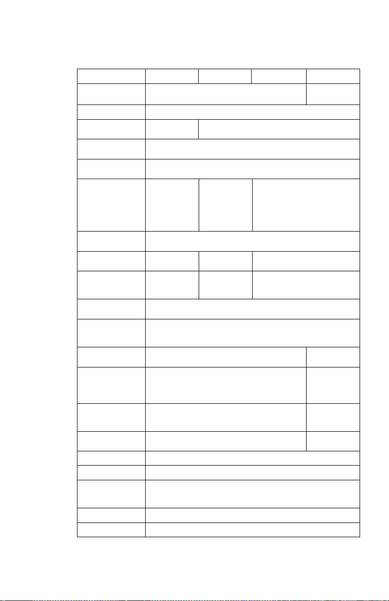
E. Specifications For Liquid Units
FLR 1000 FLR 1000-BR FLR 1000-ST FLR 1000-ST-I
Accuracy
(including linearity)
Repeatability ±0.2% Full Scale1
Pressure Rating 100 psig
Temperature Rating Operating Range: 5 to 55ºC
Temperature
Sensitivity
Wetted Materials Ryton®
O-Ring Material Standard - FKM
Fitting Material
(Standard)
Fitting Material
(Optional)
Recommended
Filtration
Compatible Liquids Low viscosity (ideally <10cS)
0-5 V DC Output
Signal
Pulse Output Signal “P” Suffix Only
4-20mA Output
Signal
Typical Power
Consumption
Response Time Typically <1 second for 63% of final value
Reliability 100,000 hours MTBF
Certifications CE Approved
Ratings IP10 (NEMA 1)
Warranty 1 year limited
Analog Signal: ±1.0% Full Scale
Optional Pulse Signal: ±3.0% F.S.1
(6.8 bar)
Storage Range: 0 to 70ºC
±0.2% F.S. 1 or less per ºC
Brass
316 Stainless
Epoxy
Glass
Sapphire
2
®
Ryton
316 Stainless
Epoxy
Glass
Sapphire
EPDM Optional
Acetal Brass Stainless Steel
PVDF
Brass
Stainless Steel
Acetal
PVDF
Stainless Steel
25 microns or less
Translucent or transparent
Minimum amount of entrapped air or gas
Standard
Minimum 2.5 KΩ load
7.5 V DC peak buffered square wave
Typically 0-400Hz
±3.0% Full Scale accuracy
N/A Non Isolated
Standard: 12 V DC @ 35 mA `
(11.5-15 V DC)
89/336/EEC (EN 55011 & EN 50082-1)
73/23/EEC Low Voltage Directive
2
1
500 psig
(34.5 bar)
Full Scale
316 Stainless
®
Ryton
Epoxy
Glass
Sapphire
Acetal
PVDF
Brass
Current loop
24 V DC @
±1.0%
N/A
N/A
<500Ω
65mA
1
1. Specifications from 10-100% of rated flow. Linearity is best fit straight line. All calibrations performed
with deionized water unless otherwise stated on calibration certificate
pg. 23 of 34
Page 24
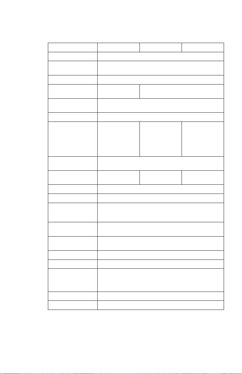
FLR 1000-D FLR 1000-BR-D FLR 1000-ST-D
Display 3.5 Digit Non Backlit LCD, 0.39” (10mm) high digits
Accuracy
(including linearity)
Repeatability ±0.2% Full Scale1
Pressure Rating 100 psig
(6.8 bar)
Temperature Rating Operating Range: 5 to 55ºC
Temperature Sensitivity ±0.2% F.S. 1 or less per ºC
Wetted Materials Ryton®
316 Stainless
Epoxy
Glass
Sapphire
O-Ring Material Standard - FKM
Fitting Material
Acetal Brass Stainless Steel
(Standard)
Fitting Material Optional Acetal, PVDF, brass, or stainless steel
Recommended Filtration 25 microns or less
Compatible Liquids Low viscosity (ideally <10cS)
Minimum amount of entrapped air or gas
0-5 V DC Output Signal Standard
Typical Power
Standard: 12 V DC @ 35 mA (11.5-15 V DC)
Consumption
Response Time Typically <1 second for 97% of final value
Reliability 100,000 hours MTBF
Certifications CE Approved
89/336/EEC (EN 55011 & EN 50082-1)
Ratings IP10 (NEMA 1)
Warranty 1 year limited
±1.0% Full Scale1
500 psig
(34.5 bar)
Storage Range: 0 to 70ºC
Brass
2
®
Ryton
316 Stainless
2
Epoxy
Glass
Sapphire
EPDM Optional
Translucent or transparent
Minimum 2.5 KΩ load
73/23/EEC Low Voltage Directive
316 Stainless*
®
Ryton
Epoxy
Glass
Sapphire)
1. Specifications from 10-100% of rated flow. Linearity is best fit straight line. All calibrations performed
with deionized water unless otherwise stated on calibration certificate
.
pg. 24 of 34
Page 25
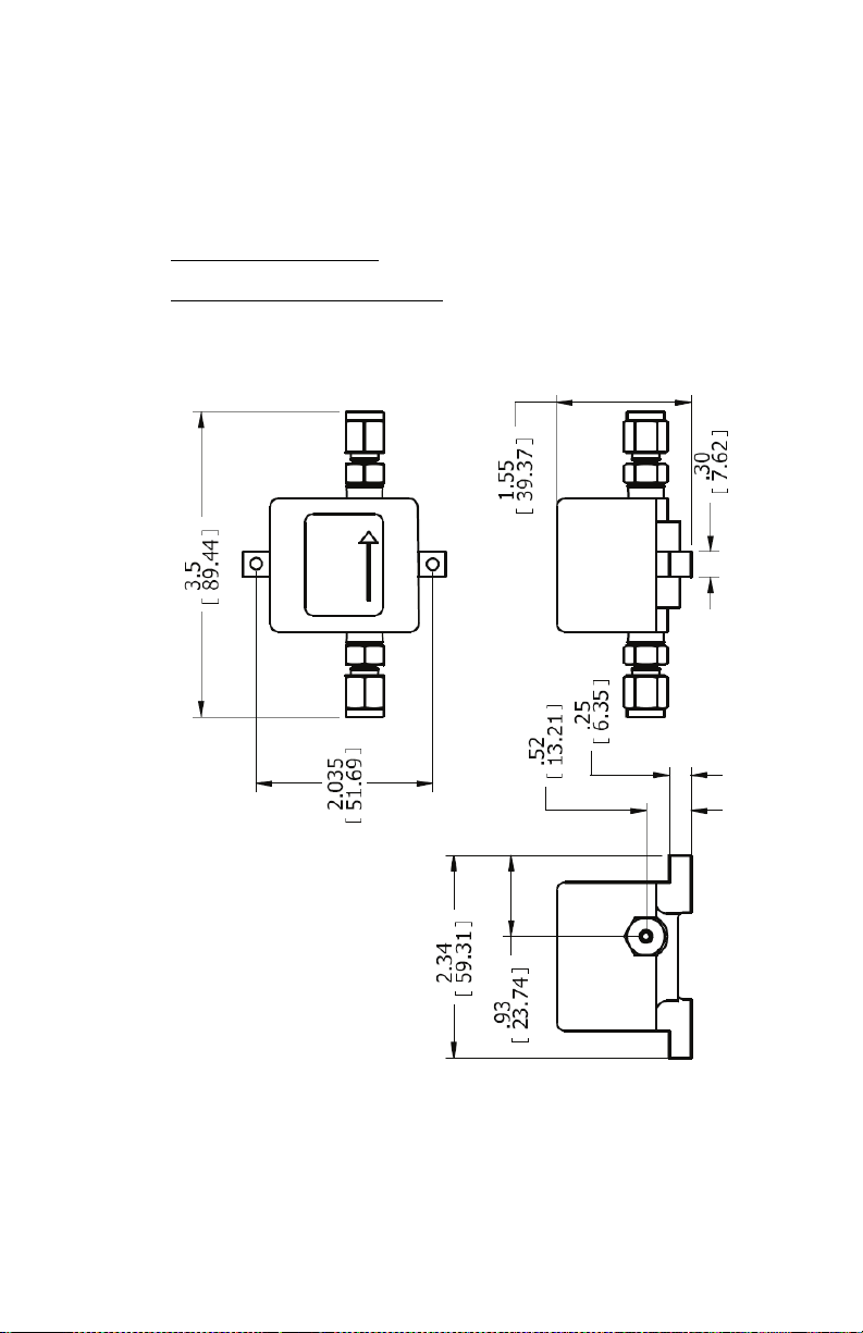
F. Dimensions
ALL DIMENSIONS IN INCHES (MILLIMETERS IN BRACKETS)
FLR 1000 For Liquids
1/4” Acetal Fittings Shown
pg. 25 of 34
Page 26
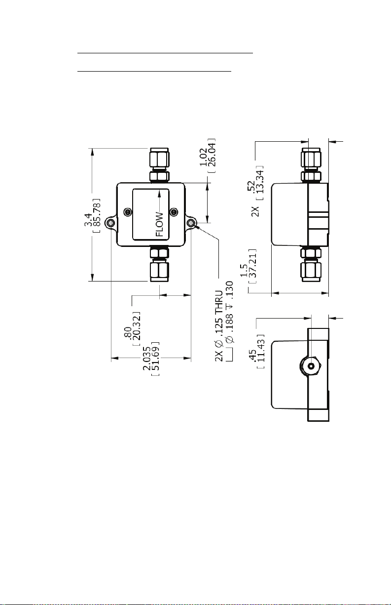
FLR 1000-BR & FLR 1000-ST For Liquids
1/4” Compression Fittings Shown
pg. 26 of 34
Page 27
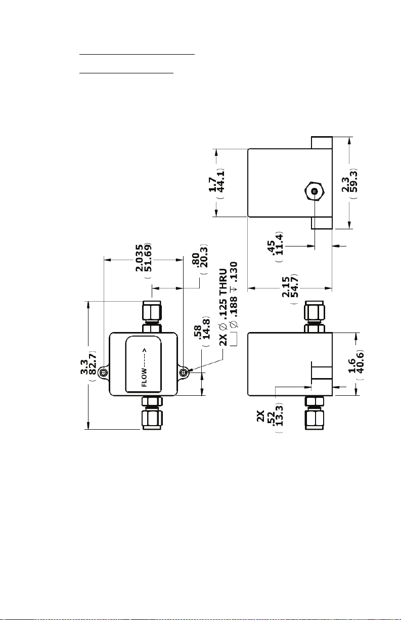
FLR 1000-ST-I For Liquids
1/4” Fittings Shown
pg. 27 of 34
Page 28
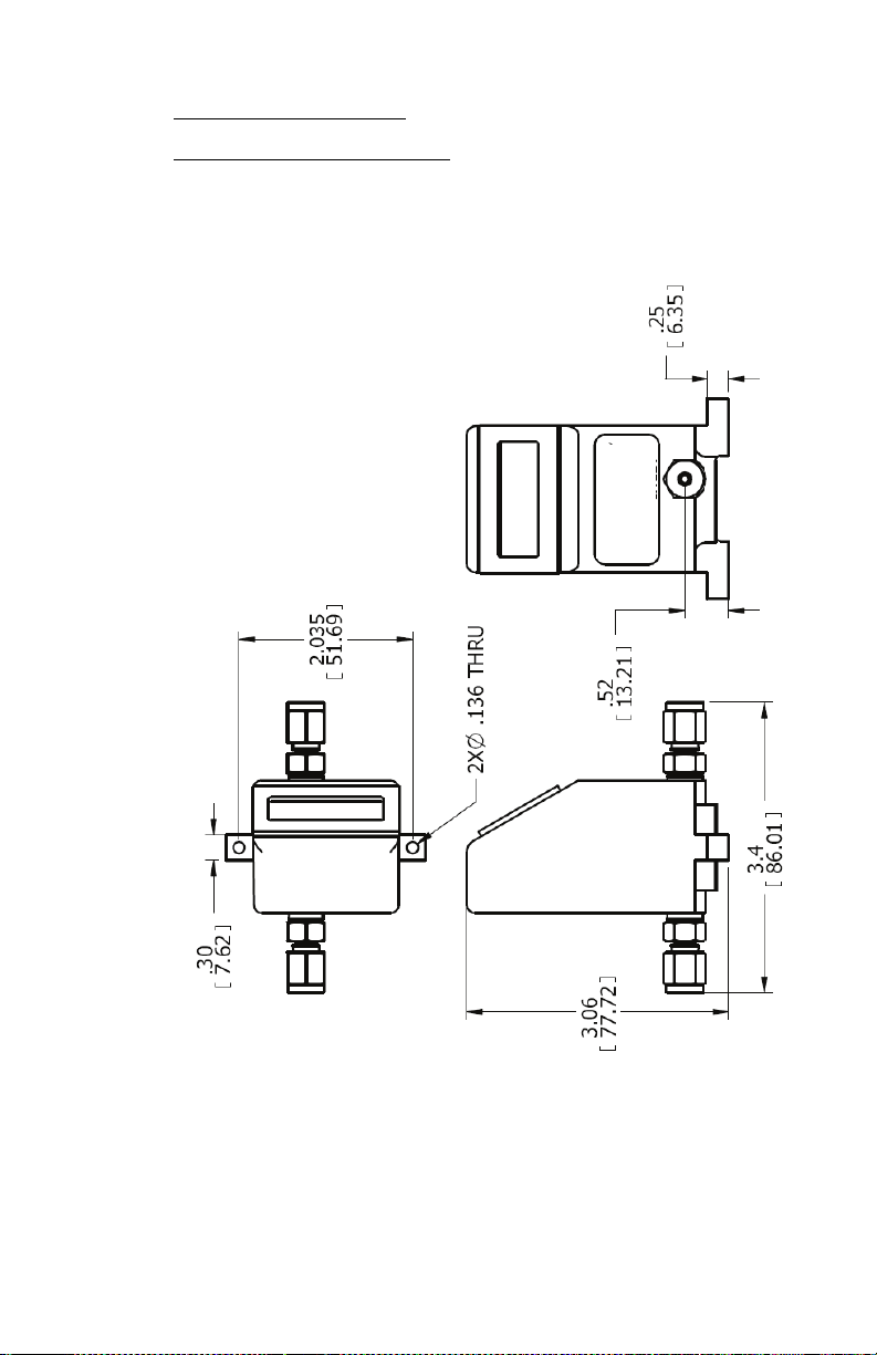
FLR 1000-D For Liquids
1/4” Acetal Fittings Shown
pg. 28 of 34
Page 29
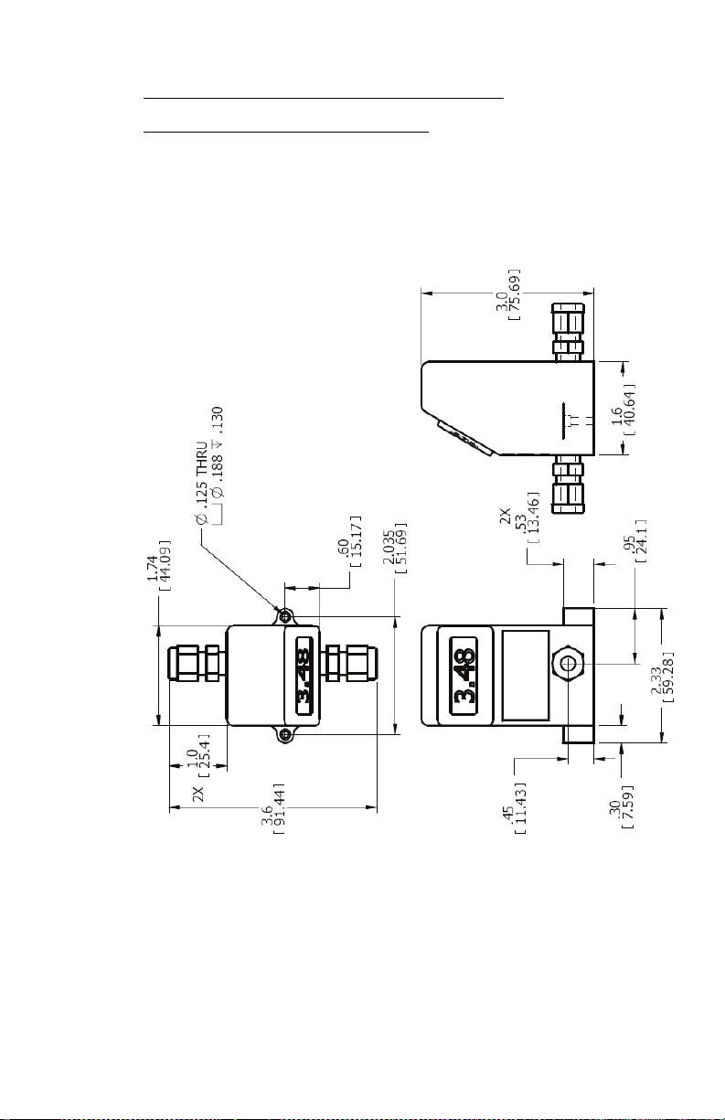
FLR 1000-BR-D & FLR 1000-ST-D For Liquids
1/4” Compression Fittings Shown
pg. 29 of 34
Page 30
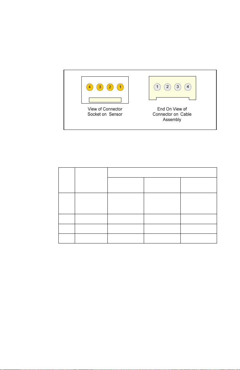
G. Connector Pin And Wire Color Cross Reference
End On View of Connector Socket and Connector
Standard Units:
Pin Cable Wire
1 Black Signal & Power
2 White Voltage Output Voltage Output Current Output
3 Red Power Positive Power Positive Power Positive
4 Green Not Used Pulse Output Not Used
Color
Voltage Voltage &
Negative
(Ground)
Unit Output
Pulse
Signal & Power
Negative
(Ground)
Current
Signal & Power
Negative
(Ground)
pg. 30 of 34
Page 31

H. Troubleshooting Guide
Symptom Possible Cause Method of Correction
No output signal or flow
indication
Flow indication is not
linear and output too low
at lower flows
No power or low power
No flow passing through
unit
Output shorted or
overloaded
Improper connection
Moisture on internal
electronics
Output circuitry damaged
Liquid not translucent
enough.
Attempting to measure
flows below the specified
minimum for the unit
Attempting to measure
flows below the specified
minimum for the unit
Liquid is too viscous
Entrapped air or gas
Mechanical sensor
assembly damaged
Apply correct power
Display or output should
read zero if there is no
flow. Increase the flow
rate until a reading is
obtained. (Do not exceed
the specified maximum
flow!)
Check electrical
connections (see section
B)
Check electrical
connections (see section
B) and ensure connector
is correctly plugged in
Allow unit to dry out in a
dry environment
Unit must be returned for
repair (see Section D3)
Contact the Omega
Engineering Service
Department for assistance
Use higher flow rates
Use higher flow rates
Best results are obtained
with liquids that have a
viscosity of 10cS or less.
Contact the Omega
Engineering Service
Department for further
information
Remove entrapped air
(see section C2)
Unit must be returned for
repair (see Section D3)
pg. 31 of 34
Page 32

Symptom Possible Cause Method of Correction
Flow indication “bounces”
or fluctuates
Flow reading accuracy is
outside the specification
Flow indication is fixed at
one value
Unit Leaks Fittings not tight enough.
Flow is actually fluctuating
Not using the fittings
supplied by the
manuafacturer
Entrapped air or gas
Turbulence in tubing or
sensor
Fluctuating input power
Mechanical sensor
assembly damaged
Liquid has a different
viscosity and / or specific
gravity than water at
20°C
Entrapped air or gas
Mechanical sensor
assembly damaged
The maximum rated flow
for the unit is being
exceeded.
Output circuits may be
damaged
Sensor assembly cracked
Correct flow source to
obtain steady flow
Use the supplied fittings
Remove entrapped air
(see section C2)
Straighten the inlet tubing
or lengthen it to at least 6”
(150mm)
Correct the power source
or change to a regulated
supply
Unit must be returned for
repair (see Section D3)
Calculate the flow
reading error / offset as
explained in section C6
Remove the entrapped air
(see section C2)
Unit must be returned for
repair (see Section D3)
Reduce the flow
Unit must be returned for
repair (see Section D3)
Tighten fittings (see section
B)
Unit must be returned for
repair (see Section D3)
pg. 32 of 34
Page 33
.
pg. 33 of 34
Page 34
M4574/1211 pg. 34 of 34
 Loading...