

Page 1
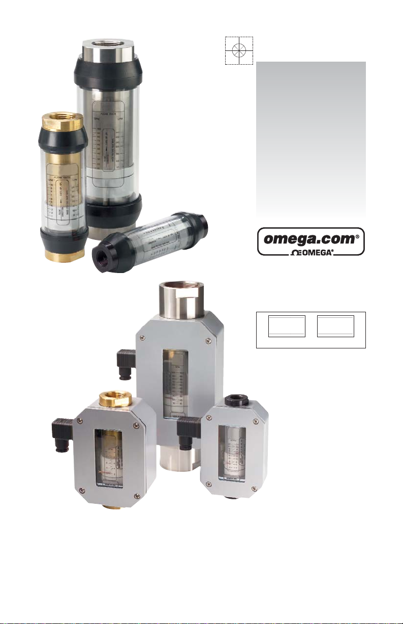
Product Manual
For Omega Flow Meters,
Alarms and Transmitters
User’s Guide
Shop online at
omega.com
e-mail: [email protected]
For latest product manuals:
omegamanual.info
ISO 9001
CERTIFIED
CORPORATE QUALITY
STAMFORD, CT
ISO 9002
CERTIFIED
CORPORATE QUALITY
MANCHESTER, UK
Page 2

Servicing North America:
U.S.A.: One Omega Drive, Box 4047
ISO 9001 Certified Stamford, CT 06907-0047
Tel: (203) 359-1660 FAX: (203) 359-7700
e-mail: [email protected]
Canada: 976 Bergar
Laval (Quebec) H7L 5A1, Canada
Tel: (514) 856-6928 FAX: (514) 856-6886
e-mail: [email protected]
For immediate technical or application assistance:
U.S.A. and Canada: Sales Service: 1-800-826-6342 / 1-800-TC-OMEGA
®
Customer Service: 1-800-622-2378 / 1-800-622-BEST
®
Engineering Service: 1-800-872-9436 / 1-800-USA-WHEN
®
TELEX: 996404 EASYLINK: 62968934 CABLE: OMEGA
Mexico: En Espan˜ol: (001) 203-359-7803 e-mail: [email protected]
FAX: (001) 203-359-7807 [email protected]
Servicing Europe:
Benelux: Postbus 8034, 1180 LA Amstelveen, The Netherlands
Tel: +31 (0)20 3472121 FAX: +31 (0)20 6434643
Toll Free in Benelux: 0800 0993344
e-mail: [email protected]
Czech Republic: Frystatska 184, 733 01 Karvina´, Czech Republic
France: 11, rue Jacques Cartier, 78280 Guyancourt, France
Tel: +33 (0)1 61 37 2900 FAX: +33 (0)1 30 57 5427
Toll Free in France: 0800 466 342
e-mail: [email protected]
Germany/Austria: Daimlerstrasse 26, D-75392 Deckenpfronn, Germany
Tel: +49 (0)7056 9398-0 FAX: +49 (0)7056 9398-29
Toll Free in Germany: 0800 639 7678
e-mail: [email protected]
United Kingdom: One Omega Drive, River Bend Technology Centre
ISO 9002 Certified Northbank, Irlam, Manchester
M44 5BD United Kingdom
Tel: +44 (0)161 777 6611 FAX: +44 (0)161 777 6622
Toll Free in United Kingdom: 0800-488-488
e-mail: [email protected]
OMEGAnet®Online Service Internet e-mail
omega.com [email protected]
It is the policy of OMEGA Engineering, Inc. to comply with all worldwide safety and EMC/EMI
regulations that apply. OMEGA is constantly pursuing certification of its products to the European New
Approach Directives. OMEGA will add the CE mark to every appropriate device upon certification.
The information contained in this document is believed to be correct, but OMEGA accepts no liability for any
errors it contains, and reserves the right to alter specifications without notice.
WARNING: These products are not designed for use in, and should not be used for, human applications.
Page 3
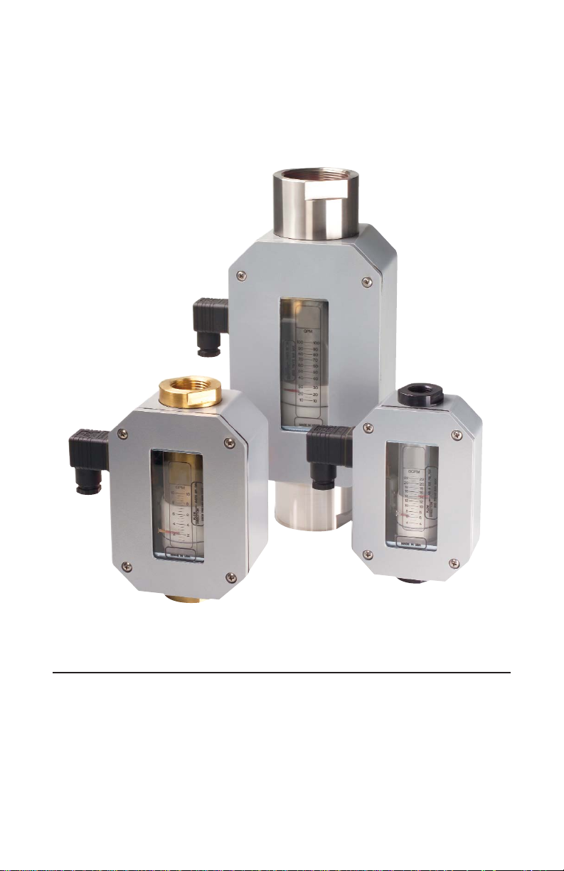
FLOW METERS
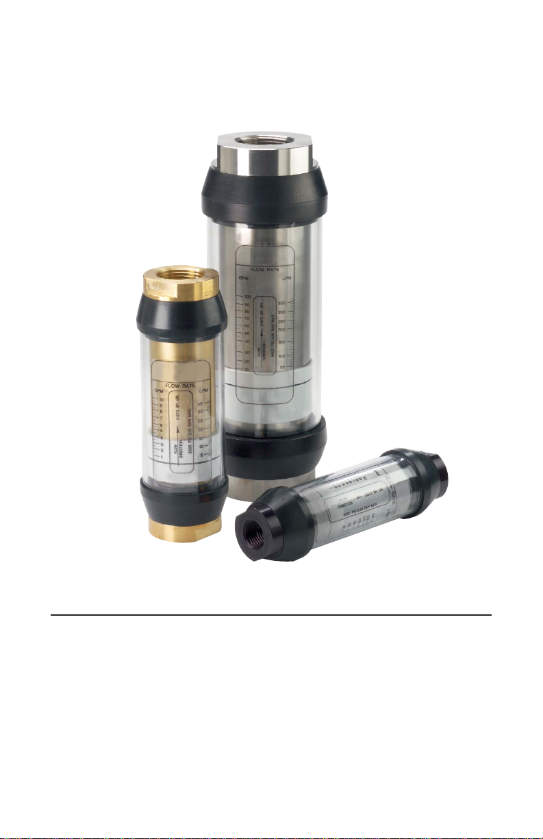
FLMX-XXXXX In-Line Flow Meters
Specification and General Information . . . . . . . . . . . . . . . . . . . . . .4-5
Installation . . . . . . . . . . . . . . . . . . . . . . . . . . . . . . . . . . . . . . . . . . .6-7
Operation . . . . . . . . . . . . . . . . . . . . . . . . . . . . . . . . . . . . . . . . . . .8-10
Pneumatic Meters Uses and Operation . . . . . . . . . . . . . . . . . . .10-13
Troubleshooting and General Maintenance . . . . . . . . . . . . . . . .14-18
Filtration and Contamination . . . . . . . . . . . . . . . . . . . . . . . . . . .19-20
Interchangeable Flow Cartridge . . . . . . . . . . . . . . . . . . . . . . . . . . .20
Page 4
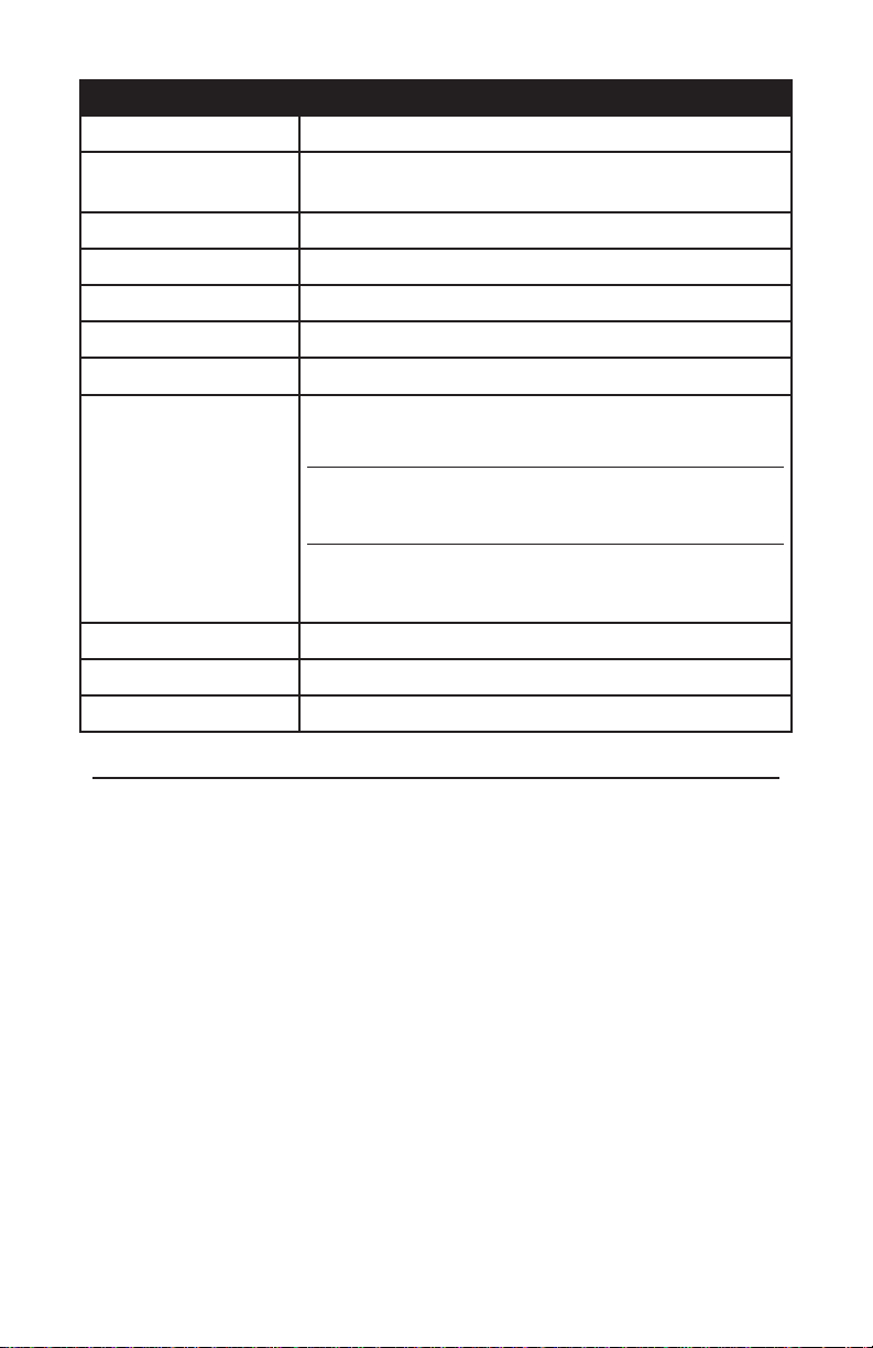
Basic Application Information
The flow meter can be installed directly in the fluid line without flow
straighteners or special piping. The meter is used to measure the flow
rate of most liquids which do not contain particles greater than 74 micron.
1) External components are sealed inside the Lexan window tube to
permit use in areas where the meter may be sprayed or washed
with soap and water.
2) Mount the meter in the most convenient location to allow easy
access for reading and maintenance.
3) The meter should NOT be mounted near hot pipes or equipment
which can cause deformation of the window tube and scale.
4) The meter should be mounted at least one foot (.3 meter) from
large electric motors, or the internal magnet may weaken or
become demagnetized.
5) Aluminum and brass meters should not be mounted where
assembled piping is not supported.
Page 4 / Flow Meters
Specifications
Casing Material Aluminum, Brass or Stainless Steel #304
Maximum Pressure
Aluminum and Brass: 3500 psi (240 Bar)
Stainless Steel #304: 6000 psi (413 Bar)
Maximum Temperature 240ºF (115ºC)
Reading Direct Reading - 360º Ref. Line (Non-Electrical)
Scale Accuracy +/- 4% FS, Center 1/3 of scale +/- 2.5% FS
Repeatability +/- 1% FS
Port Sizes 1/8" - 2" NPTF, #6 - #32 SAE (No Brass) 1/4" - 2" BSP
Installation Dimensions
(Port Sizes/Dimensions)
1/4", 3/8", 1/2" 1-7/8" O.D. x 6-9/16" Length
(48mm O.D. x 167mm Length)
3/4", 1" 2-3/8" O.D. x 7-5/32" Length
(60mm O.D. x 182mm Length)
1-1/4", 1-1/2" 3-1/2" O.D. x 10-1/8" Length
(90mm O.D. x 258mm Length)
Installation Orientation Horizontal or Vertical (Scaled Vertically)
Flow Straighteners Not Required
Test Fluid Mobile DTE 25 Medium @ 110ºF (43ºC)
Page 5

Warning and Precautionary Ar eas
1) The meters are designed to operate in systems that flow in only one
direction: the direction of the arrow on the flow scale. Attempting operation
in the reverse direction may cause damage to the meter or other system
components.
2) The window tube of standard meters is made of Lexan. Lexan can be
safely cleaned with soap and water. However, many other cleaning agents
can damage Lexan, causing discoloration or crazing. If you are unsure of
your cleaning agent, call the General Electric Lexan Compatibility
Reference Line at 800-845-0600.
3) To retain accuracy and repeatability many internal moving parts are
precision machined and require filtration of at least 74 micron or a
200 mesh screen.
4) All meters are tested and calibrated at our test facility using a light
hydraulic oil. The units are well drained, but some oil residue may still remain
within the meters. Please check the compatibility with your fluid. The meter
may have to be cleaned before use. (See “Cleaning & Inspection”)
5) When installing aluminum or brass meters onto steel pipe caution should
be taken not to over tighten the pipe connections. The thread in the meter
end fittings may strip if over tightened.
6) Aluminum and brass meters should not be used in systems where the
assembled piping is not supported. Heavy weight may cause the meter
to bend or malfunction.
7) Operating Temperature: In standard meters, several components have a
maximum temperature rating of 240ºF (115ºC).
8) Operating Pressure: All meters are tested at a burst pressure three times
of operating pressure. Meters should not be used over the operating
pressure rating.
9) Pressure and flow surges may disengage the outer magnet follower from
the transfer magnet. If this occurs, a shock suppressor should be used to
eliminate malfunction.
10)Teflon tape: Caution should be used when using Teflon tape on pipe
thread joints. Leave at least 1/8" (3mm) of pipe thread exposed from end
of pipe when applying tape.
11)These meters, as well as many other meters, use an internal transfer
magnet in the design. Because of this magnet, be aware of the following:
a) Keep flow meters away from computer disks and tapes.
b) If metal particles are moving through the system, a magnetic
filter may be required.
Page 5 / Flow Meters
Page 6

INSTALLATION
Basic Installation Instructions
The meters are mounted in-line and are direct reading. The meters
can be mounted in a vertical or horizontal position as long as the fluid
is flowing in the direction of the arrow on the flow scale. No straight
pipe is required before or after the meter. In fact, 90° elbows can be
installed on both ends without any noticeable flow variation.
When installing a meter, apply “Teflon Tape” or “Liquid Teflon Sealant”
on pipe threads. If tape is used, be sure to leave 1/8" (3 mm) of pipe
thread exposed on end of pipe. Position filter in front of meter and in
a location that allows easy access for routine maintenance. Refer to
“Warnings and Precautionary Areas” for additional information.
INSTALLATION DOS AND DON'T
To obtain satisfactory operation from a flow meter, the following points
should be considered:
DO:
install a pressure gauge near the inlet of the meter
place throttling valves at the outlet of the meter
use pipe sealer on the connections
install a union on one side of the meter for easy removal for
maintenance and calibration
install solenoid valves at meter outlet (as far downstream as possible)
mount in any orientation: vertical, horizontal or upside down
DO NOT:
place restrictions between the meter’s pressure gauge meter inlet
use in systems where reverse flow is possible
place meter in non-aligned piping
over-flow the meter by more than 150% of maximum reading
operate at pressures and temperatures greater than specified
*
install restrictions between pressure gauges and the meter inlet
*
install solenoid valves at the meter inlet
*
pneumatic flow meter applications
Page 6 / Flow Meters
Page 7

Fluid Flow in Rever se Dir ection
The standard monitor will not permit flow in the reverse direction
(opposite direction to the arrow printed on the flow rate scale). In the
reverse direction, the meter will behave in a manner similar to a leaky
check valve.
Prolonged flow in the reverse direction will cause damage to the
standard monitor's internal mechanism that could result in inaccurate
readings or premature failure of the meter. If the standard meter will
be installed in a system where reverse flow is possible, it is recommended that a check valve be installed in parallel with the meter in
order to facilitate reverse flow around the meter. Check valves are
readily available through fluid component distributors.
Bi-Directional Flow Measurement
In certain situations it may be necessary to measure flow rates in both
directions. For a small additional fee, an option for bi-directional flow
measurement may be specified. Meters that include this option are
designated by a "-BI" suffix attached to the end of the model code.
If the part number label on the meter that is being installed shows a
model code containing the "-BI" suffix, then the meter may be
installed in any orientation regardless of flow direction.
Page 7 / Flow Meters
Page 8

OPERATION
Operating Principles
Omega has developed a line of unique flow meters which combine
the simplicity of a sharp-edged orifice disk and a variable area flow
meter. See Illustration 1 “Flow Meter Cross Section” on page 9.
The meters are tubular, with all internal wetted parts sealed within
the body casing. Running through the center of the body casing is
a tapered center shaft which is centered in the bore by pilot disks at
each end. Encircling the shaft is a sharp-edged, floating orifice disk,
transfer magnet and return spring. The disk and transfer magnet are
held in the “no flow” position by the biased return spring.
As the flow moves through the meter it creates a pressure differential
across the floating orifice disk, forcing the disk and transfer magnet
against the return spring. As flow increases, the pressure differential
across the disk increases, forcing the disk and transfer magnet to
move along the tapered center shaft. As flow decreases, the biased
return spring forces the disk and transfer magnet down the tapered
center shaft, returning to the “no flow” position.
In metal casing meters we cannot see the movement of the floating
orifice disk and transfer magnet because they are sealed inside the
body casing. Therefore, a magnet follower is positioned around the
outside of the body casing and is magnetically coupled to the internal
transfer magnet. As the flow rate increases, the internal magnet
moves along the tapered center shaft (inside the body casing) and
the magnet follower moves along the outside of the body casing
(under the scale).
Page 8 / Flow Meters
Page 9
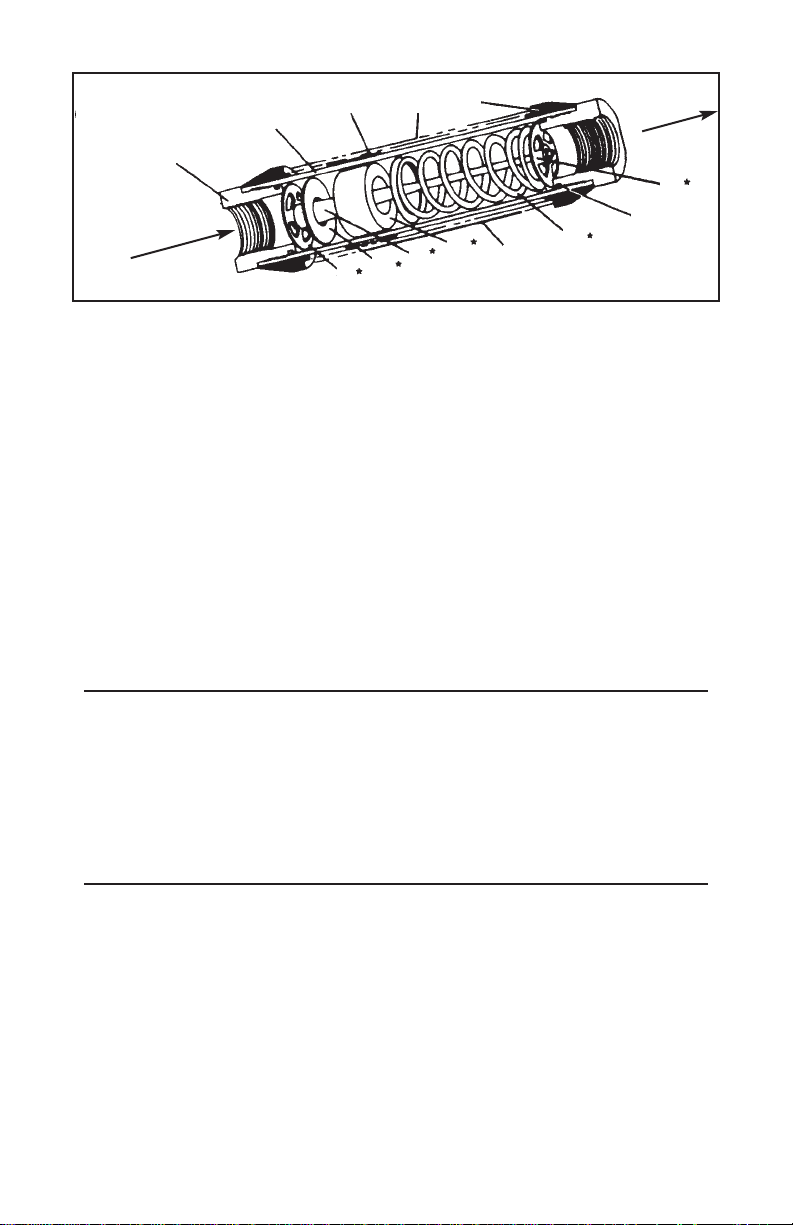
1. End Porting 8. Flowing Sharp-Edged Orifice Disk
2. Body Casing 9. Tapered Center Shaft
3. Magnet Follower 10. Transfer Magnet
4. Window Tube 11. Scale
5. Window Seal 12. Return Spring
6. Seal Assembly 13. Retainer Ring
7. Pilot Disk
* Cartridge contains: 7, 8, 9, 10, 12 & 13
Reading the Meter
Notice the black reference line which runs 360° around the white
magnetic follower. This reference line moves under the scale in direct
relation to the movement of the internal orifice disk. When fluid is
flowing, the flow rate through the meter is read by lining up the black
reference line with the closest rate line on the external flow scale.
Specific Gravity or Density Effect
Standard meters are calibrated for either WATER with a specific
gravity of 1.0 or OIL with a specific gravity of .873. The floating disk
meter is effected by fluid density as are most other similar types of
meters. Omega meters have less of this effect because of the sharpness of the floating orifice disks being used.
Page 9 / Flow Meters
12
11
10
8
7
9
13
6
5
4
3
2
1
Flow
Direction
Flow
Direction
FLOW METER
(CROSS SECTION)
Illustration 1
Page 10

The indicated flow reading will read high for heavier fluids and low for
lighter fluids. Acorrective factor can be applied to the standard scale
or a special scale can be added at a slight additional cost. When
flowing other specific gravities, the basic equations below can be used.
For WATER Meters use: 1.0/Specific Gravity x scale reading
For OIL Meters use: .873/Specific Gravity x scale reading
Viscosity Effect
The meters incorporate a unique floating, sharp-edged orifice disk.
The floating, sharp-edged orifice disk offers greater operating stability
and accuracy over a wide range of viscosities.
PNEUMATIC METER USES & OPERATING THEORY
Rugged, high pressure, pneumatic meters are designed for
permanent installation in compressed gas systems. These products
provide a low cost means to measure compressor volumetric outputs,
pneumatic tool consumptions and other industrial gas flow rates.
The meters operate using the variable annular orifice method with
compression spring return –the identical method used in our field
proven liquid flow rate meters. The product’s follower, where the
measurement is indicated, is magnetically coupled through a high
pressure casing to the meter’s internal orifice assembly.
Benefits of these design features are:
high operating pressure
linear displacement of the follower with respect to flow rate
high turn-down ratios
measuring accuracy within ±4% of full-scale
operation in any mounting orientation
Meters are offered in three standard materials of construction:
aluminum for standard monitoring applications to 600 PSIG
brass for media/material compatibility
stainless steel for compatibility and operation to 1000 PSIG.
Page 10 / Flow Meters
Page 11
Measuring ranges cover 1.5-12 SCFM through 150-1300 SCFM.
Twenty-four port sizes from 1/8" through 2" in NPT, SAE and BSP
can be ordered to meet specific plumbing requirements. Pneumatic
meters are also available in alarm and transmitter configurations for
electronic monitoring applications.
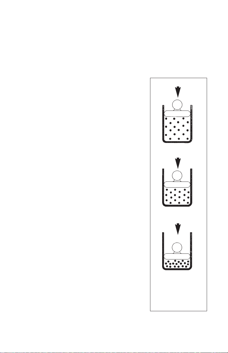
Standard Cubic Feet
Meters are calibrated to measure the flow of
compressible media (gases) in SCFM – standard cubic feet per minute. A“standard” cubic
foot is defined as a cubic foot of dry air
at standard atmospheric conditions: 70ºF and
14.7 PSIA (0 PSIG) measured at sea level.
When a standard cubic foot of air is compressed, its actual volume will decrease proportionally as absolute pressure increases.
For example, a standard cubic foot of air’s
actual volume will decrease by 50% and density will increase by 100% as the air is compressed from atmospheric pressure 14.7 PSIA
(0 PSIG) to 29.4 PSIA (14.7 PSIG). See
Illustration 2.
There are three factors that affect the Flow
Meter Calibration: specific gravity, pressure
and temperature. Meters are calibrated for air
(specific gravity of 1.0) at 70ºF and 100 PSIG.
Most low pressure rotameters are calibrated
at 0 PSIG and require corrections for use at
any other pressure.
Omega meters are designed for pneumatic
systems where pressures between 90 -110
PSIG are used. In these common applications, a monitor with a standard calibration
can be read directly without applying corrections.
Page 11 / Flow Meters
14.7 PSIA (0 PSIG)
29.4 PSIA (14.7 PSIG)
58.8 PSIA (44.1 PSIG)
Illustration 2
Illustrates the effect of
different pressures on
the volume of gas.
Page 12
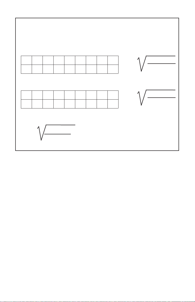
DENSITY CORRECTION FACTORS
SCFM (indicated) x (CF) = SCFM (Actual) CF= (F1) x (F2) X (F3)
Note: all correction factors need not be used.
Table 1. (f1) PRESSURE CORRECTION FACTORS (inlet pressure)
Table 2. (f2) TEMPERATURE CORRECTION FACTORS
Table 3. (f3) SPECIFIC GRAVITY CORRECTION FACTOR
f1= correction factor for other than 100 PSI inlet.
f2= correction factor for other than 70ºF.
f3= correction factor for other than air at 1.0 Sp. Gr.
Correction Factors
If a meter is installed in a system where conditions differ from the
standard listed above, correction factors will need to be applied to
retain the design accuracy of the meter. The appropriate correction
factor equations are detailed above. To assure the best monitoring
accuracy, pressure and temperature measurements should be taken
directly at the meter’s inlet port.
Special Scales
Special calibrations can be performed to correct for the following
system characteristics:
system pressure
system temperature
media specific gravity
various measuring units (i.e. LPM, LPS, m3/hr, etc.)
any combination of the above
Consult the factory or your distributor for details and prices.
Page 12 / Flow Meters
f1= 14.7 + psig
114.7
f2= 530
460 + ºF
f3=1
Sp. Gr.
psig 25 50 75 100 125 150 175 200
f
1
.56 .75 .88 1.0 1.11 1.2 1.29 1.37
ºF 10º 30º 50º 70º 90º 110º 130º 150º
f
2
1.08 1.04 1.02 1.0 .98 .96 .95 .93
Page 13

Page 13 / Flow Meters
Selecting the Proper Monitor
To order a pneumatic flow meter the following information is required:
pipe size and port style
media (air, nitrogen, argon,etc.) – for material compatibility and
specific gravity considerations
approximate flow range required
1
system pressure: nominal, maximum, minimum
system temperature
Flow Range
1
Estimating the flow rate in a compressed gas system may seem
complicated, but with some research and a few simple equations
an educated guess can be made.
Two suggested methods are:
Method 1
A compressor is typically rated in SCFM output at a certain pressure
and efficiency. If the rating cannot be located or is unknown, an estimate of compressor output can be obtained by the following formulas:
1-stage compressors:
motor HP/0.179 = SCFM @ 100 PSIG
2-stage compressors:
motor HP/0.164 = SCFM @ 100 PSIG
3-stage compressors:
motor HP/0.159 = SCFM @ 100 PSIG
Method 2
If all of the potential of a compressor is not being used (the unit
cycles on and off) or if flow rate in excess of compressor capacity is
being consumed (the compressor cannot meet the demand), a summation of machine usages can be totaled to determine the maximum
flow rate. Most machine tools that use compressed air specify the
maximum consumption of the tool.
Page 14
TROUBLESHOOTING & MAINTENANCE
Page 14 / Flow Meters
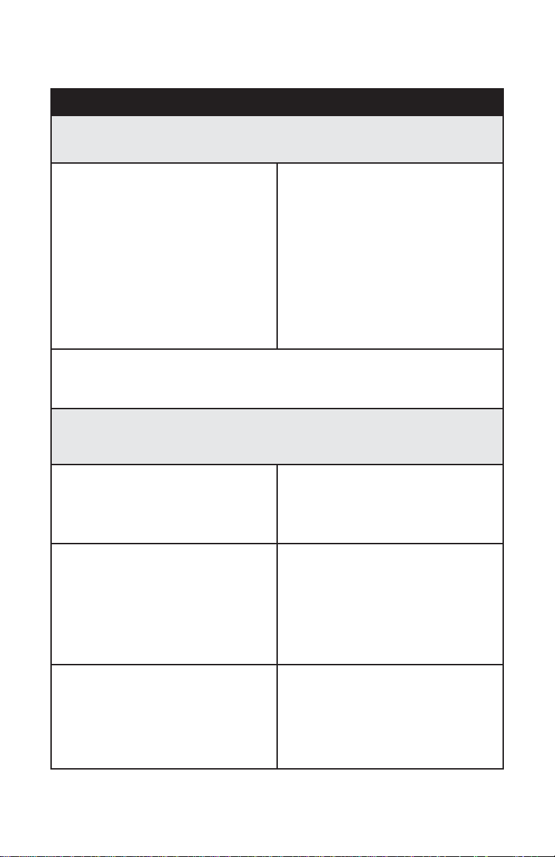
TROUBLESHOOTING CHART
Malfunction: Magnet follower sticks in mid-scale and will not
return to the “no flow” position.
Possible Cause:
Horizontal/Vertical Mount
Particulate, Teflon tape, rust or other
foreign matter is holding the internal
parts form returning.
Horizontal/Vertical Mount
A surge or shock in the fluid flow
moved the internal magnet faster that
the external follower could follow, thus
separating the follower from the magnet.
Corrective Action:
Disassemble and inspect meter for
contamination. Install proper filtration
or problem may reoccur.
Warning: Shut down systems before removing meter from flow line. Remove meter from
system. Tip the meter so the arrow on the flow scale points upward. This should
return the magnet follower to the “no flow” position. Add some type of surge
protection, or problem my reoccur.
Malfunction: Meter scale reading is off an equal amount
at all points and the magnet follower still
moves freely.
Possible Cause:
Reading the scale using the top or
bottom edge of the magnet follower.
Corrective Action:
Be sure to read the scale using the
black reference line which runs around
the magnet follower.
Possible Cause:
Fluid being monitored may not be
compatible with standard meter scale.
Corrective Action:
Standard meters are calibrated for
.873 SP. Gr. oil at 110° (43°C) using
Mobile DTE 25 Medium fluid. Check
your fluid data for a variance, or call
the factory for assistance.
Possible Cause:
All meters are calibrated in the vertical
position.
Corrective Action:
Check with the factory for a correction
factor or for a replacement scale corrected for horizontal use.
Page 15

Page 15 / Flow Meters
TROUBLESHOOTING CHART (CONTINUED)
Malfunction: Window tube is cracking or crazing.
Possible Cause:
Using incompatible cleaning solution
on Lexan window tube.
Corrective Action:
Use soap & water or a mild degreaser
(Stoddard or Naptha) to clean Lexan
tube. To check the compatibility of
your cleaning fluid, call General
Electric’s Lexan Compatibility
Reference line at 800-845-0600.
Malfunction: Scale is fogging or coming loose.
Possible Cause:
Ambient or fluid temperature is too
high.
Corrective Action:
Relocate meter in another area where
temperature specifications are not being
exceeded.
Possible Cause:
Using incompatible cleaning solvents
on scale.
Corrective Action:
Use soap and water.
Page 16
Disassembly
Important: It is not necessary to remove window tube or window
seals to clean the meter. Note also how the meter
disassembles for easy of reassembly.
Warning: Shut down system before removing meter from flow line.
1. Use a clean dry cloth
to remove all foreign
material from exterior
of meter, especially
around threaded ends.
2. Remove meter from the
flow line.
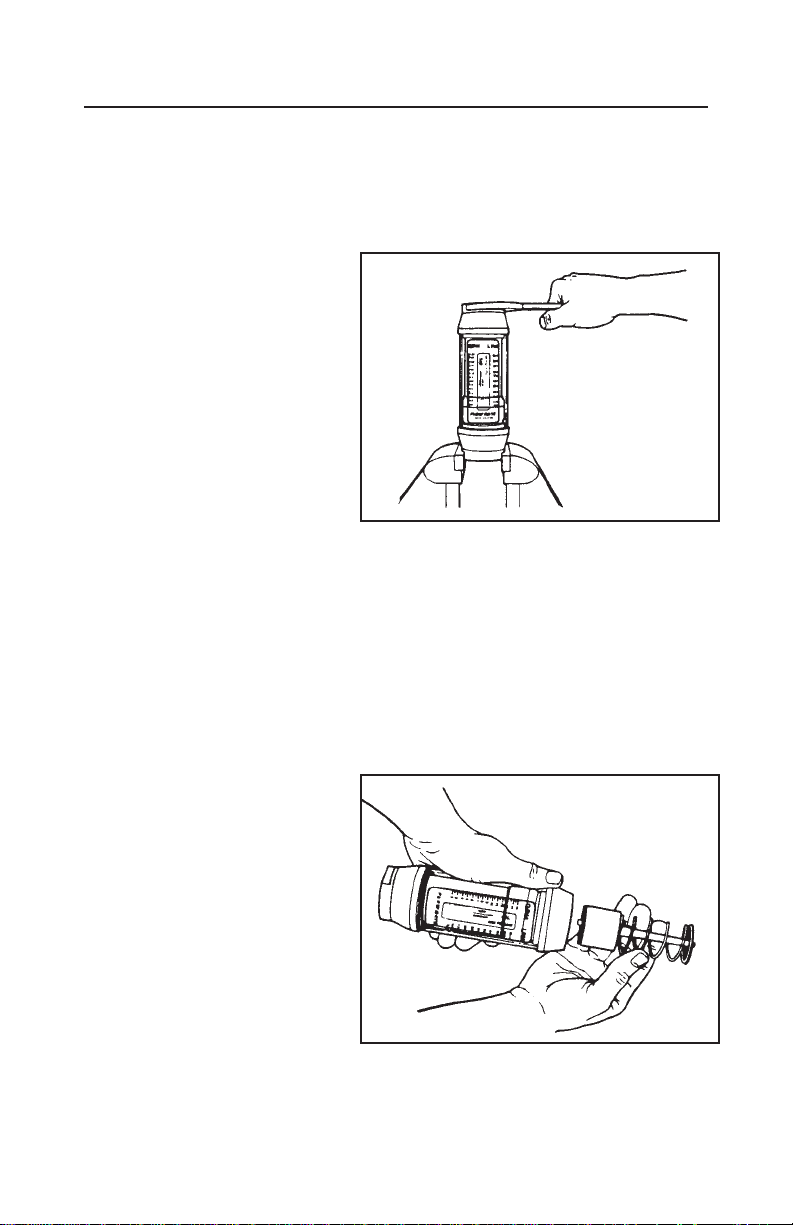
3. With the arrow on the
scale pointing upward,
mount the meter in a
vice. See Illustration 3.
Use the flats of the inlet
end porting when securing the meter in the vice.
Important: DO NOT wrench or tighten vice on Lexan tube.
4. Install a wrench across the flats of the outlet end porting and turn
counterclockwise to loosen assembly. Do not remove end porting
at this time.
5. Remove meter from vice. Hold the meter so the end port that is
loose, is on top. Remove loose end porting.
6. Tilt the open end of meter
over a clean cloth to
expose inner cartridge.
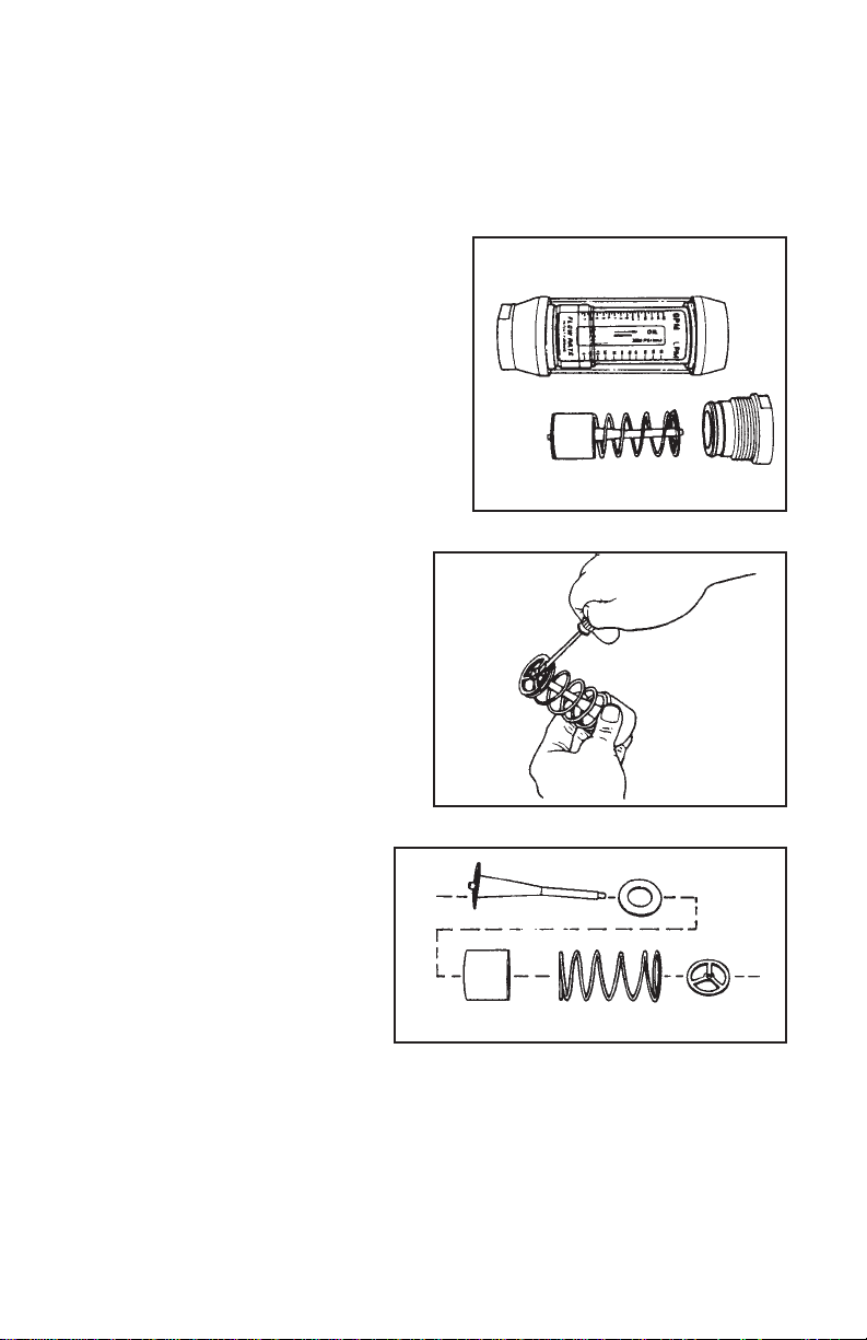
See Illustration 4.
Remove inner cartridge
assembly from body
casing. Note: Because
the transfer magnet is
magnetically coupled to
the magnetic follower,
you will notice a slight
resistance when removing
cartridge. If cartridge does
not slide out, insert a wooden dowel in opposite end of meter and
push or lightly tap on dowel until cartridge comes loose.
Page 16 / Flow Meters
Illustration 3
Illustration 4
Page 17
IMPORT ANT: If inner cartridge does not slide out freely, it may be
sign of contamination. The transfer magnet is a powerful ALNICO
magnet. Keep it away from metal chips and fillings. They may be
hard to remove when reassembling and will cause premature failure.
7. Examine inner cartridge or level
of contamination.
A. If inner cartridge has a low
level of contamination and is
functioning properly, no further
disassembly is required.
Proceed to “Cleaning and
Inspection.” See Illustration 5.
B. If inner cartridge appears
to be highly contaminated
or damaged, it should be
completely disassembled
for cleaning and inspection.
Proceed with Step 8.
8. Remove outlet side
(spring end) retainer clip,
See Illustration 6, which
secured pilot disk to tapered
center shaft.
9. Remove return spring,
transfer magnet and
floating orifice disk.
See Illustration 7.
10. Proceed to “Cleaning
and Inspection.” After
the meter is cleaned
reassemble parts in
reverse order of
disassembly.
IMPORTANT:
Always use new retainer clips for reassembly. 3/8" and 1/2" = Waldes
No. 5105-12H. 3/4 and 1" and 1-1/4" and 1-1/2" = Waldes No. 510518H, or obtain at no charge from the factory.
Page 17 / Flow Meters
Illustration 5
Illustration 6
Illustration 7
Page 18

Cleaning and Inspection
Note: If the inner cartridge is damaged or contaminated beyond repair, the complete
meter can be sent to the manufacturer for evaluation. The manufacturer will
inspect, repair, and/or replace parts as needed according to the warranty.
1. Inspect inner cartridge and body casing for contamination.
If the inner cartridge did not slide out freely, it may be a sign of
contamination. Locate and eliminate the source of contamination
before reconnecting meter to the system or the same problem
will reoccur. It may be necessary to install finer filtration or a
magnetic filter in the system.
2. Soak inner cartridge assembly (or individual parts, depending on
level of disassembly) in a suitable cleaning solvent. Naptha or
Stoddard is recommended.
CAUTION: When using an air hose wear proper eye protection.
3. Remove parts from solvent. Use an air hose and/or scrub with a
light brush to remove any remaining contaminants. Remove any
magnetized particles from transfer magnet.
4. Inspect inner cartridge for scored or worn parts. Replace parts as
needed. (Parts are available from your local distributor.)
5. Remove any contaminants from inside body casing.
6. Clean Lexan widow tube with soap and water, or a compatible
cleaning solvent. IMPORTANT: Some solvents may cause
damage to Lexan tube, check compatibility of solvent being used.
7. Clean and inspect seal assemblies (O-rings and seals) for nicks
or cuts. Replace as needed.
8. Clean and inspect the meter every six months.
Properly filtered meters will provide years of trouble-free service. If
the meter is not properly filtered, it may be damaged and malfunction.
Meter damage caused by excessive contamination in not covered
under warranty.
Page 18 / Flow Meters
Page 19

CONTAMINATION AND FILTRATION
Recommended Filtration
The manufacturer recommends system filtration of at least 74 micron
filter or a 200 mesh screen. It has been found that if inadequate filtration
has caused meter failure, it will normally fail in the open position. Some
systems may require a magnetic filter. IMPORTANT: Meter damage
caused by excessive contamination is not covered under warranty.
Stabilized Contamination
The goal of filtration is to create effective protection from system
contamination. Proper filtration stabilizes contamination to allow
fluid components to function properly. A fluid system is considered
stabilized when, “contamination in” equals “contamination out”.
Proper filtration must reduce initial contamination to a stabilized level
within an acceptable time period. the system should be stabilized in
time to prevent premature wear or damage to meter components.
Contamination Sources
Fresh Fluid
When fresh fluid is stored in holding tanks, it may be contaminated
with scale or metal flakes from inside the tank. To prevent this type of
contamination, be sure to filter fresh fluid before adding to the system.
New Machinery Contamination
When building new machines, a certain amount of built-in contamination
is unavoidable. Typical built-in contamination consists of dust, dirt,
chips, fibre, sand, flushing solutions, moisture, weld splatters and
pipe sealants. Flushing the system before operation can reduce
contamination, but cannot eliminate it totally. Unless the system is
flushed at a high velocity, some contamination will not be dislodged
until the system is in operation. System contamination can cause fluid
component malfunction.
Environmental Contamination
When performing routine maintenance, the system’s fluid is commonly
exposed to environmental contamination. Exercise caution during
routine maintenance to prevent this type of contamination. Be sure to
change breather filter and systems air filter regularly.
Page 19 / Flow Meters
Page 20

Self-Generation Contamination
Self-generated contamination is a product of wear, cavitation,
fluid breakdown and corrosion. Systems that are carefully flushed,
maintained, and have fresh fluid added, mainly have self-generated
contamination. In this case, proper filtration can prevent fluid
component malfunction.
INTERCHANGEABLE FLOW CARTRIDGE
Basic Application Information
This unique design permits the exchange of many different cartridges
within the same meter, thus, allowing the conversion to other flow
ranges at minimal cost. The substitute cartridge offers different flow
ranges at the same low pressure drop as the original. Each cartridge
comes with a new cartridge, scale and installation instructions. Check
with your meter distributor for prices and delivery.
Page 20 / Flow Meters
Page 21
FLOW ALARMS
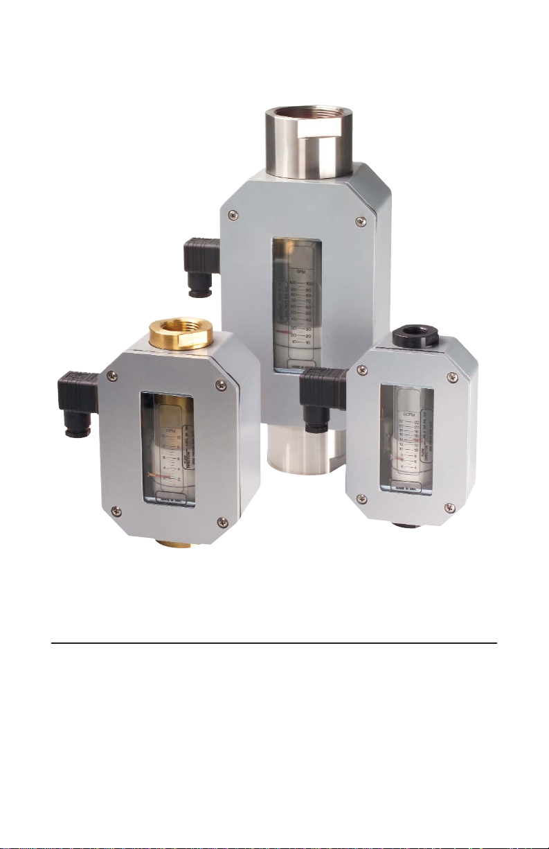
FLMG, FLMH and FLMW Series
with -R1 or -R2 Option
General Information and Overview . . . . . . . . . . . . . . . . . . . . . . . . .22
Switches/Switch Specifications . . . . . . . . . . . . . . . . . . . . . . . . .23-24
Electrical Connection . . . . . . . . . . . . . . . . . . . . . . . . . . . . . . . . .24-25
Standard Control Circuits . . . . . . . . . . . . . . . . . . . . . . . . . . . . . .26-27
Page 22
NOTE: Installation, operation and cleaning instructions for the basic flow meter
cartridge can be found in the first section of this manual. The following instructions are specifically for meters with electrical switches for flow alarms.
General Information
Omega’s Flow Alarms are typically used to make or break a set of electrical contacts to signal a limit setting. They may be used to turn on a
warning light, sound a bell or horn, or even to shut down a process. The
switches on the alarm can be configured to open or close a contact for
an increasing or decreasing set point. Decreasing flow set points may
be located anywhere in the lower 2/3 of the scale while increasing set
points may be located anywhere in the upper 2/3 of the scale.
Overview
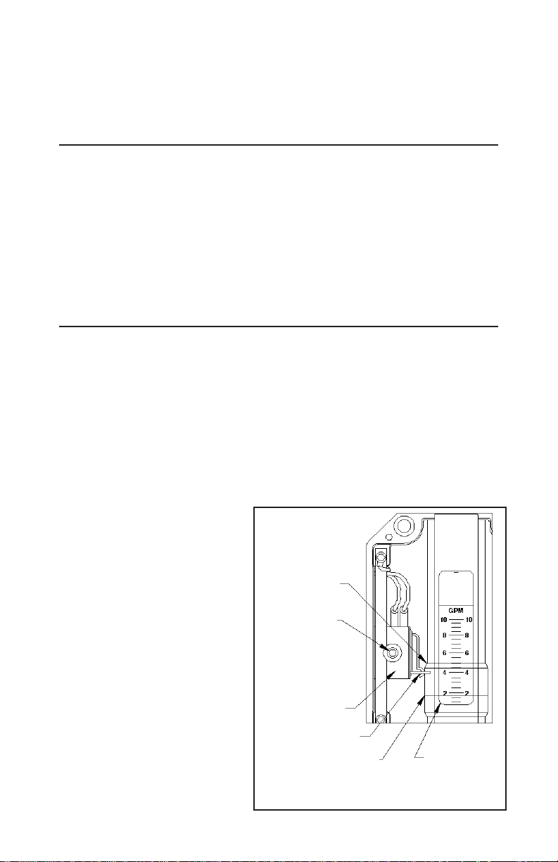
Illustration 1 shows the primary mechanism for a single-switch flow
alarm. Dual-switch flow alarms contain two sets of these same components, but have a slightly different electrical wiring diagram (Wiring
to the DIN connector is described on page 24.) The factory default
configuration for the alarm switch is for decreasing flow, as shown
in Illustration 1. Dual alarm units contain one additional switch
configured for increasing flow. If an increasing flow alarm is desired,
it should be specified when the unit is ordered.
The follower moves in
unison with an orifice plate
inside of the unit’s pressure
vessel via a magnetic
coupling in order to indicate
flow rate. As the follower
moves with changes in
flow rate, the flow rate is
determined by relating the
position of the flow indica-
tor line to the increments
on the flow rate scale.
Page 22 / Flow Alarms
Illustration 1
FOLLOWER
POINTER
SWITCH GLIDE
SCREW
ALARM
SWITCH
FLOW INDICATOR
LINE
FLOW RATE
SCALE
Page 23
The pointer indicates the set point for the alarm switch. In Illustration
1, the switch will be actuated at all flow rates below 4 GPM. To
change the set point, simply loosen the switch glide screw one (1)
turn and slide the switch to the desired position along the flow rate
scale. When the pointer is pointing to the desired flow rate, re-tighten
the switch glide screw.
Switches
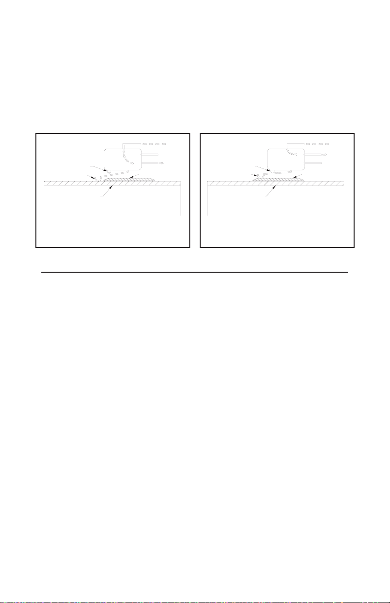
The switch is a simulated roller, lever operated low force microswitch.
The specifications for this switch are listed on page 4. The switch is
actuated when movement of the follower causes the switch lever to
be lifted. In Illustration 2, the switch has not yet been actuated, and
the electrical circuit is through the normally closed (NC) contact.
Illustration 3 shows the switch after it has been actuated. In this scenario, the electrical circuit is through the normally open (NO) contact.
Precautions
Be certain to properly ground the unit via the ground (G) pin
located on the unit’s din connector.
In order to avoid accidentally removing the switch glide screw,
never loosen it by more than one or two turns. This screw can be
difficult to replace if accidentally removed.
Avoid over tightening the switch glide screw.
When the switch adjustments are complete, make certain that the
wires that are attached to the switch have not been moved into a
location that will interfere with the follower or the switch lever.
Do not make any modifications to the unit’s internal wiring.
Page 23 / Flow Alarms
TRIGGER
COMMON
SWITCH LEVER
FOLLOWER
METER CASING
NO
NC
Illustration 2 Illustration 3
TRIGGER
COMMON
SWITCH LEVER
FOLLOWER
METER CASING
NO
NC
Page 24
Switches Specifications
Type Form C, dry contact
UL/CSA Rating 10 & 1/4 hp, 125 or 250 VAC
1/2 A, 125 VDC & 1/4A, 250 VDC
3A, 125 VAC “L” lamp load
Mechanical Life >10,000,000 cycles
Actuating Mechanical Simulated roller, lever operated,
low force
Connectors 3/16" tab
Double Break Switch (Special) Form Z - 10A &1/2hp,
125/250 VAC
Electrical Connections
Standard Flow Alarms
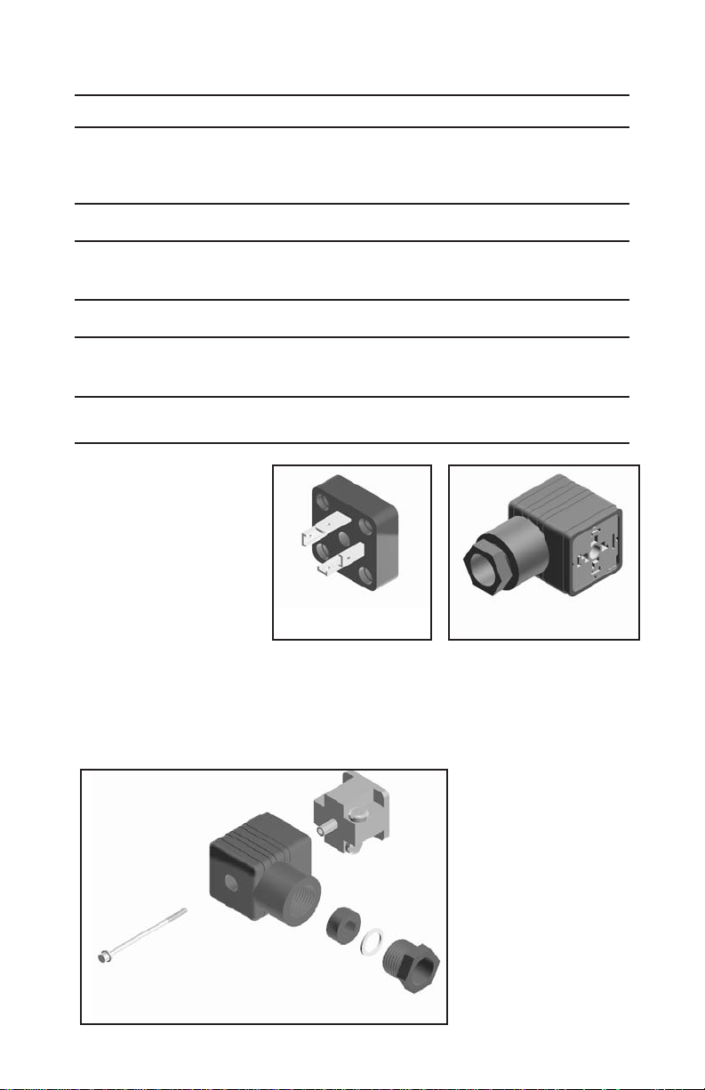
are pre-wired with 4pin Hirschmann-type
DIN connectors which
consist of a male
section as shown in
Illustration 4 and the
female section shown
in Illustration 5. To open the female section, first remove the screw,
then lift the connector portion out of the casing by inserting the head
of a screwdriver into the slot marked for that purpose. Illustration 6
shows the disassembled female section.
Page 24 / Flow Alarms
Illustration 4
Illustration 6
Illustration 5
Page 25
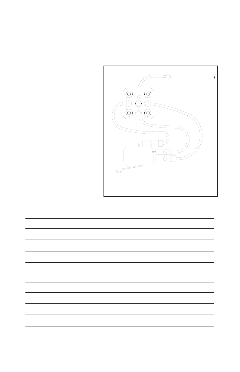
Illustration 7 shows the connections for a standard, single switch
Flow Alarm as they are shipped from the factory. The wiring for other
types of connections are outlined in the tables below. For additional
details, please consult the factory.
Alternates to the standard
Hirschmann-type DIN
connector are available on
a custom basis. The Flow
Alarm may be outfitted
with a variety of different
electrical connections
including conduit fittings,
cable-type connectors and
cord grip/pigtail interfaces.
Almost any commercially
available electrical
connector may be used.
If an alternate connector
is desired, please consult
Omega.
Wiring Code: Standard Single Switch
White - Common Terminal #1of DIN
Black - N.C. Contact Terminal #2 of DIN
Red - N.O Contact Terminal #3 of DIN
Green - Enclosure Ground Terminal “G” of DIN
Wiring Code: Dual Switch Alarm
White - Both Common Terminal #1of DIN
Black - Decreasing N.O. Contact Terminal #2 of DIN
Red - Increasing N.O. Contact Terminal #3 of DIN
Green - Enclosure Ground Terminal “G” of DIN
Page 25 / Flow Alarms
Illustration 7
GREEN
NO
NC
BLACK
WHITE
COMMON
RED
TO ENCLOSURE
GROUND
Page 26
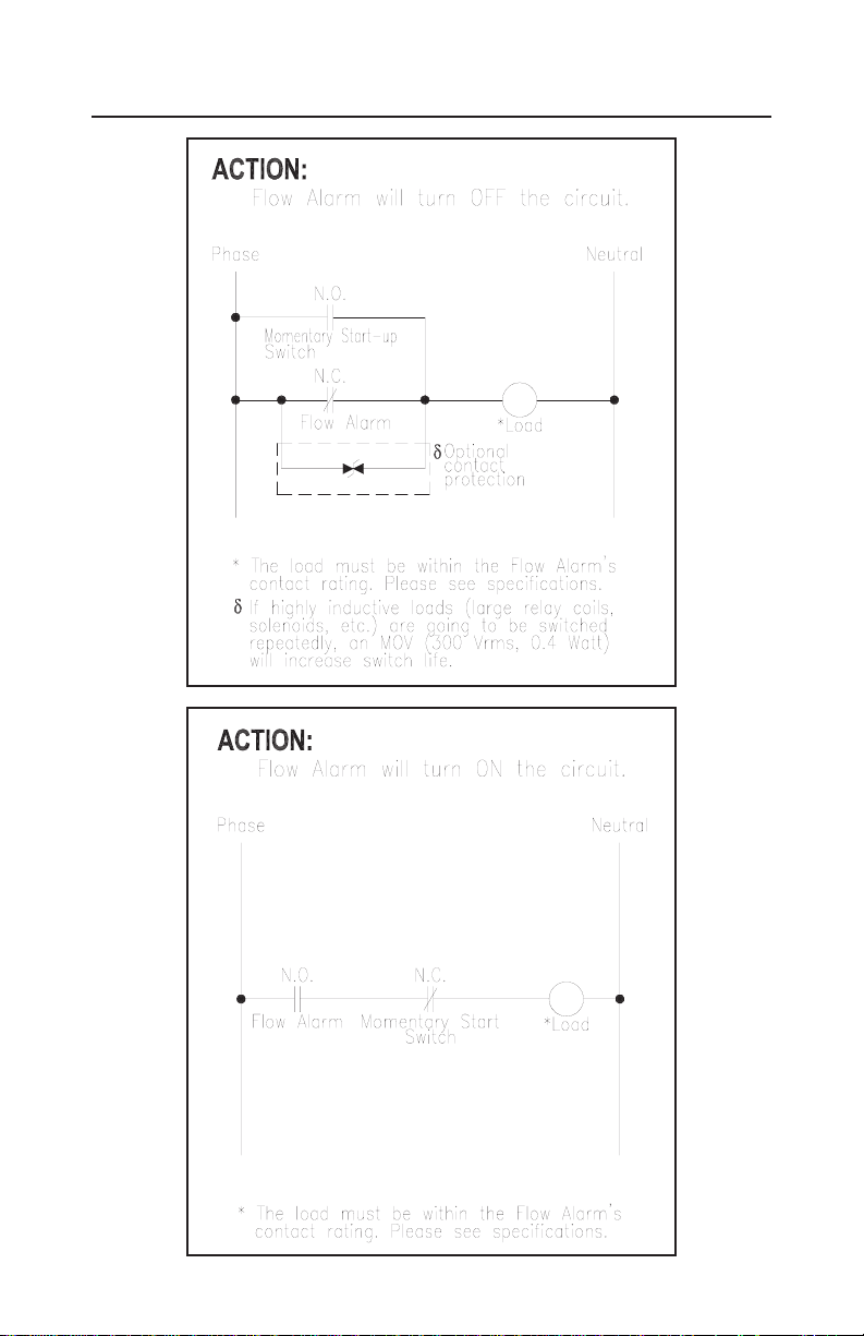
Standard Control Cir cuits
Page 26 / Flow Alarms
Page 27
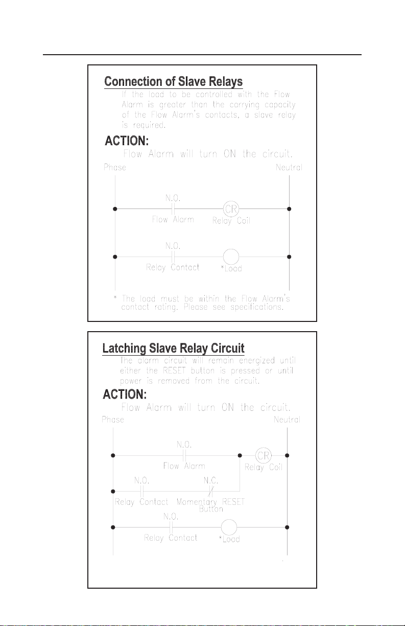
Standard Control Cir cuits
Page 27 / Flow Alarms
* The load must be within the flow alarm’s and the slave
relay’s contact rating. Please see specifications.
Page 28

NOTES:
_ _ _ _ _ _ _ _ _ _ _ _ _ _ _ _ _ _ _ _ _ _ _ _ _ _ _ _ _ _ _ _ _ _ _ _ _ _ _ _ _ _ _ _ _ _ _ _ _ _ _ _ _ _ _
_ _ _ _ _ _ _ _ _ _ _ _ _ _ _ _ _ _ _ _ _ _ _ _ _ _ _ _ _ _ _ _ _ _ _ _ _ _ _ _ _ _ _ _ _ _ _ _ _ _ _ _ _ _ _
_ _ _ _ _ _ _ _ _ _ _ _ _ _ _ _ _ _ _ _ _ _ _ _ _ _ _ _ _ _ _ _ _ _ _ _ _ _ _ _ _ _ _ _ _ _ _ _ _ _ _ _ _ _ _
_ _ _ _ _ _ _ _ _ _ _ _ _ _ _ _ _ _ _ _ _ _ _ _ _ _ _ _ _ _ _ _ _ _ _ _ _ _ _ _ _ _ _ _ _ _ _ _ _ _ _ _ _ _ _
_ _ _ _ _ _ _ _ _ _ _ _ _ _ _ _ _ _ _ _ _ _ _ _ _ _ _ _ _ _ _ _ _ _ _ _ _ _ _ _ _ _ _ _ _ _ _ _ _ _ _ _ _ _ _
_ _ _ _ _ _ _ _ _ _ _ _ _ _ _ _ _ _ _ _ _ _ _ _ _ _ _ _ _ _ _ _ _ _ _ _ _ _ _ _ _ _ _ _ _ _ _ _ _ _ _ _ _ _ _
_ _ _ _ _ _ _ _ _ _ _ _ _ _ _ _ _ _ _ _ _ _ _ _ _ _ _ _ _ _ _ _ _ _ _ _ _ _ _ _ _ _ _ _ _ _ _ _ _ _ _ _ _ _ _
_ _ _ _ _ _ _ _ _ _ _ _ _ _ _ _ _ _ _ _ _ _ _ _ _ _ _ _ _ _ _ _ _ _ _ _ _ _ _ _ _ _ _ _ _ _ _ _ _ _ _ _ _ _ _
_ _ _ _ _ _ _ _ _ _ _ _ _ _ _ _ _ _ _ _ _ _ _ _ _ _ _ _ _ _ _ _ _ _ _ _ _ _ _ _ _ _ _ _ _ _ _ _ _ _ _ _ _ _ _
_ _ _ _ _ _ _ _ _ _ _ _ _ _ _ _ _ _ _ _ _ _ _ _ _ _ _ _ _ _ _ _ _ _ _ _ _ _ _ _ _ _ _ _ _ _ _ _ _ _ _ _ _ _ _
_ _ _ _ _ _ _ _ _ _ _ _ _ _ _ _ _ _ _ _ _ _ _ _ _ _ _ _ _ _ _ _ _ _ _ _ _ _ _ _ _ _ _ _ _ _ _ _ _ _ _ _ _ _ _
_ _ _ _ _ _ _ _ _ _ _ _ _ _ _ _ _ _ _ _ _ _ _ _ _ _ _ _ _ _ _ _ _ _ _ _ _ _ _ _ _ _ _ _ _ _ _ _ _ _ _ _ _ _ _
_ _ _ _ _ _ _ _ _ _ _ _ _ _ _ _ _ _ _ _ _ _ _ _ _ _ _ _ _ _ _ _ _ _ _ _ _ _ _ _ _ _ _ _ _ _ _ _ _ _ _ _ _ _ _
_ _ _ _ _ _ _ _ _ _ _ _ _ _ _ _ _ _ _ _ _ _ _ _ _ _ _ _ _ _ _ _ _ _ _ _ _ _ _ _ _ _ _ _ _ _ _ _ _ _ _ _ _ _ _
_ _ _ _ _ _ _ _ _ _ _ _ _ _ _ _ _ _ _ _ _ _ _ _ _ _ _ _ _ _ _ _ _ _ _ _ _ _ _ _ _ _ _ _ _ _ _ _ _ _ _ _ _ _ _
_ _ _ _ _ _ _ _ _ _ _ _ _ _ _ _ _ _ _ _ _ _ _ _ _ _ _ _ _ _ _ _ _ _ _ _ _ _ _ _ _ _ _ _ _ _ _ _ _ _ _ _ _ _ _
_ _ _ _ _ _ _ _ _ _ _ _ _ _ _ _ _ _ _ _ _ _ _ _ _ _ _ _ _ _ _ _ _ _ _ _ _ _ _ _ _ _ _ _ _ _ _ _ _ _ _ _ _ _ _
_ _ _ _ _ _ _ _ _ _ _ _ _ _ _ _ _ _ _ _ _ _ _ _ _ _ _ _ _ _ _ _ _ _ _ _ _ _ _ _ _ _ _ _ _ _ _ _ _ _ _ _ _ _ _
Page 28 / Flow Alarms
Page 29
FLOW
TRANSMITTERS
FLMG, FLMH, and FLMW Series
with the -MA Option
General Information and Overview . . . . . . . . . . . . . . . . . . . . . .30-31
Output Connections . . . . . . . . . . . . . . . . . . . . . . . . . . . . . . . . . .31-35
Connectors . . . . . . . . . . . . . . . . . . . . . . . . . . . . . . . . . . . . . . . . . . .36
User Adjustments . . . . . . . . . . . . . . . . . . . . . . . . . . . . . . . . . . . . . .37
Trouble Shooting . . . . . . . . . . . . . . . . . . . . . . . . . . . . . . . . . . . . . . .38
Page 30
NOTE: Installation, operation and cleaning instructions for the basic flow meter
cartridge can be found in the first section of this manual. The following instructions are specifically for meters equipped with signal conditioning circuitry for
transmitting a proportional output signal.
General Information
Omega’s Flow Transmitters are typically used to transmit a signal
proportional to flow rate to a process control computer, a PLC, a
recorder, or a panel-mount display. The Flow Transmitters are used
as the primary input device to record flow rates through hydraulic and
pneumatic systems.
The universal output transmitter circuit employed by the Omega Flow
Transmitter is capable of producing output signals of 4-20 mA, 0-5
VDC, and 0-2000 Hz square wave pulse. A1-5 VDC signal may be
obtained by connecting a 249 Ω resistor to the 4-20 mA loop.
Overview
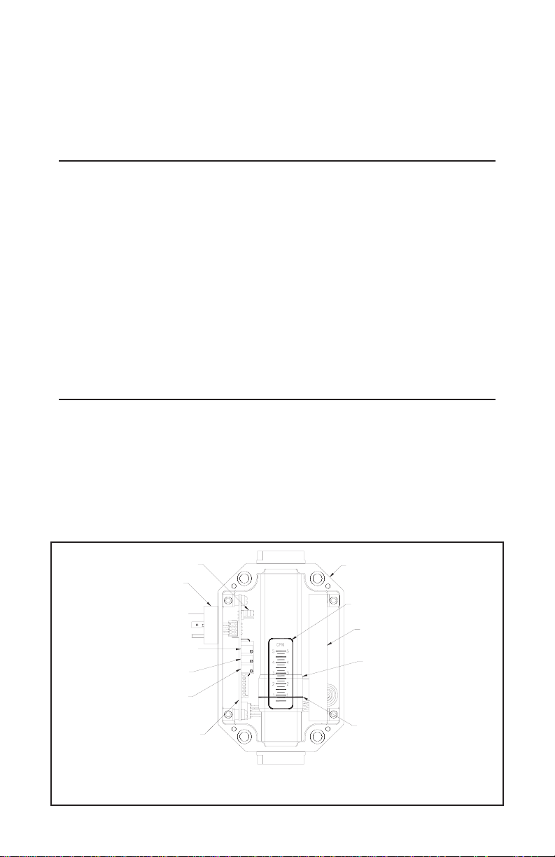
Illustration 1 shows a Flow Transmitter with the cover removed.
The follower moves in unison with an orifice plate inside of the unit’s
pressure vessel via a magnetic coupling in order to indicate flow rate.
As the follower moves with changes in flow rate, the flow rate is
determined by relating the position of the flow indicator line to the
increments on the flow rate scale.
Page 30 / Flow Transmitters
Illustration 1
PROGRAMMABLE JUMPER
NEMA 4X ENCLOSURE
SENSOR ASSEMBLY
FOLLOWER
FLOW INDICATOR LINE
FLOW RATE SCALE
DIN CONNECTOR
4-20 mA OFFSET ADJUST
4-20 mA SPAN ADJUST
0-5 VDC SPAN ADJUST
SIGNAL CONDITIONING CIRCUIT
Page 31

The sensor array located in the sensor assembly sends a signal
relative to the position of the follower to the signal conditioning circuit.
The signal conditioning circuit converts the signal from the sensor
array into three different signals that are all directly proportional to the
reading that is determined by relating the position of the flow indicator
line to the flow rate scale.
The user may choose between reading a 0-2000 Hz square wave
pulse, a 0-5 VDC analog signal, or a two-wire 4-20 mA analog signal
by connecting to the appropriate pins on the 4-pin Hirschmann® din
connector and by placing the programmable jumper in the appropriate
position for the desired output.
An analog 1-5 VDC output may also be obtained by configuring the unit
for the two-wire 4-20 mA output and then connecting a 249W ohm
resistor to the current loop. The exact output pins and jumper positions
that correspond to each output are discussed later in this manual.
4-20 mA Output Connections
Input Voltage:
The supply voltage must be between 12 and 35 VDC.The maximum
resistance that may be placed within the current loop is given by the
following formula:
Where: R
max
= the maximum resistance that may be placed in the
current loop (
Ω)
Vs= the value of the supply voltage (VDC)
Page 31 / Flow Transmitters
R
max
= 50(Vs- 12)
Page 32
4-20 mA Output Connections
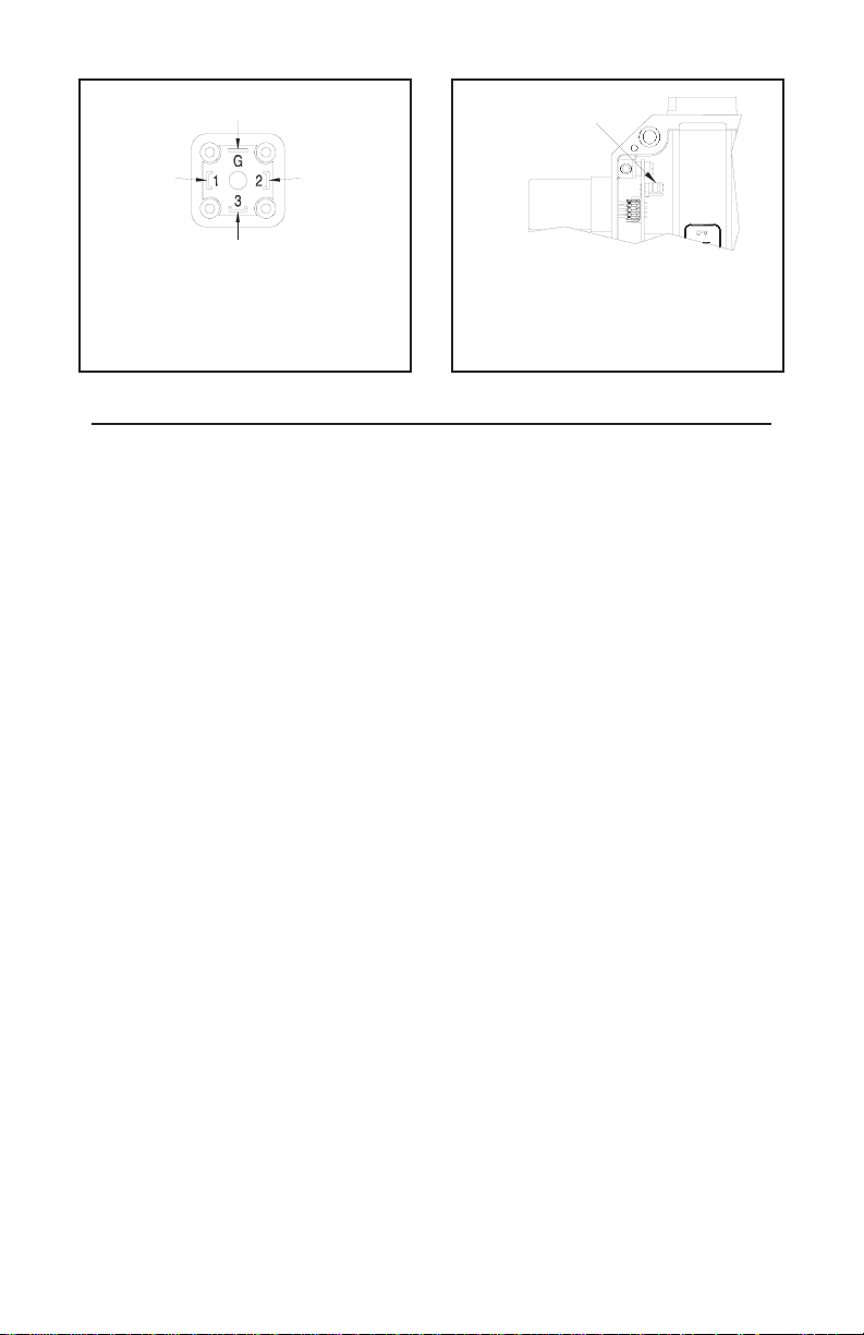
Wiring Instructions (Refer to Illustrations 2 and 3 above):
1) Move the programmable jumper on the signal conditioning
board into the position closest to the meter’s outlet, as shown
in Illustration 3.
2) Connect the positive DC power source (+12 to +35 VDC) to
terminal #1 on the din connector
3) Connect terminal #2 of the din connecter to the positive current
input on the receiving device.
4) If the power source does not originate from the receiving device,
the negative side of the power supply must be connected to the
signal ground of the receiving device.
5) If the transmitter is operating properly, the green LED on the
signal conditioning board will illuminate dimly at zero flow and
will increase in intensity as flow increases.
Page 32 / Flow Transmitters
Illustration 2 Illustration 3
PROGRAMMABLE JUMPER
IN POSITION CLOSEST
TO METER OUTLET
JUMPER POSITION - 4-20 mA
ELECTRICAL CONNECTION - 4-20 mA
NO CONNECTION
PIN #1
+12 - 35 VDC
PIN #2
4 - 20 mmA OUT
NO CONNECTION
Page 33
0-5 VDC Output Connections
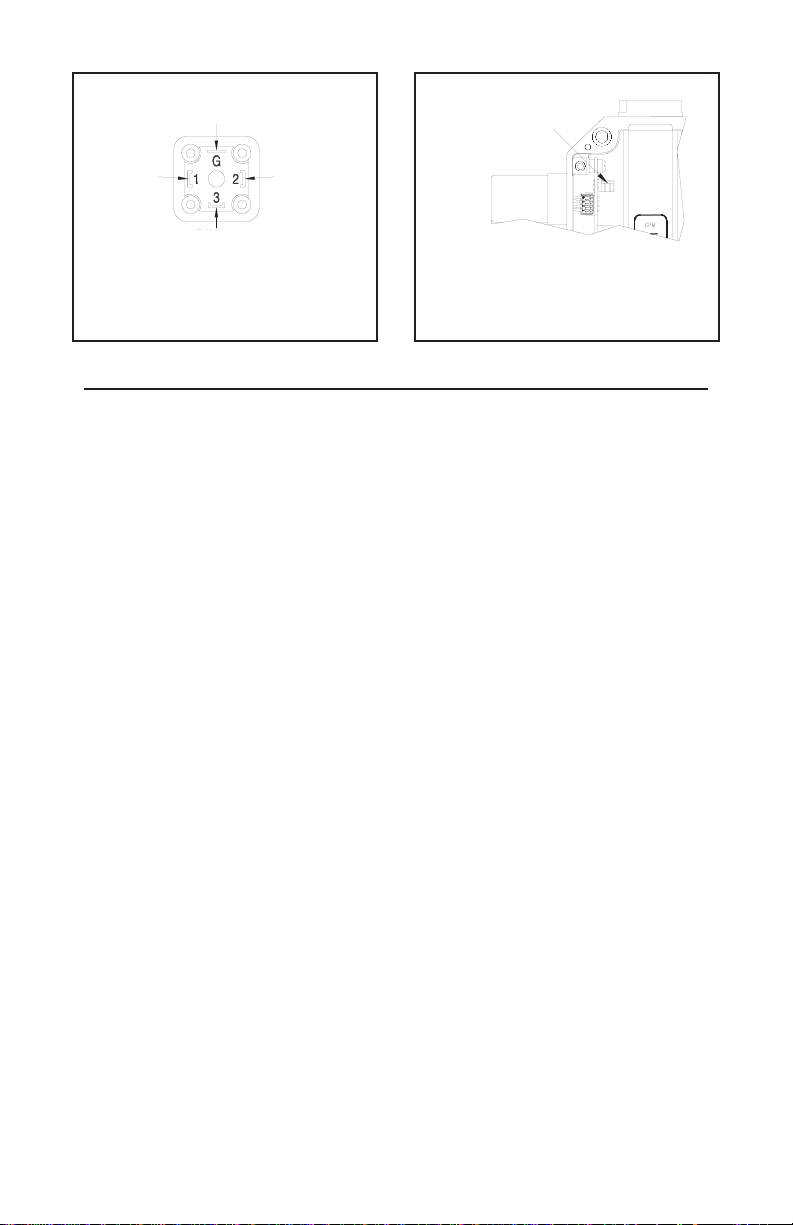
Wiring Instructions (Refer to Illustrations 4 and 5 above):
1) Move the programmable jumper on the circuit board into the
position closest to the meter’s inlet, as shown in Illustration 5.
2) Connect the positive voltage source (+12 to +35 VDC) to terminal
#1 of the din connector.
3) Connect terminal #2 of the din connector to the negative side of
the DC voltage source.
4) Connect terminal #3 of the din connector to the 0-5 VDC input of
the receiving device.
5) If the power source does not originate at the receiving device, a
wire will need to be connected between the negative side of the
voltage source and the signal ground of the receiving device.
6) If the transmitter is operating correctly, the green LED on the
circuit board will illuminate brightly when power is applied to the
unit.
NOTE: The input impedance (resistance) of the receiving device
must not be lower than 100W or non-linearities may result.
Lower impedance will not damage the transmitter.
Page 33 / Flow Transmitters
Illustration 4
Illustration 5
PROGRAMMABLE JUMPER
IN POSITION CLOSEST
TO METER INLET
JUMPER POSITION - 4-20 mA
PIN #3
0 - 5 VDC OUTPUT
ELECTRICAL CONNECTIONS - 0 - 5VDC
NO CONNECTION
PIN #1
+12 - 35 VDC
PIN #2
DC GROUND
Page 34
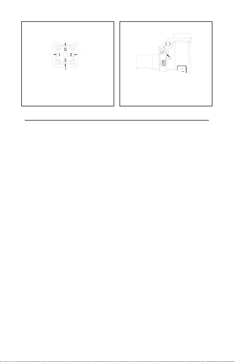
0-2000 Hz Pulse Output Connections
Wiring Instructions (Refer to Illustrations 6 and 7 above):
1) Move the programmable jumper on the circuit board into the
position closest to the meter’s inlet, as shown in Illustration 7.
2) Connect the positive voltage source (+12 to +35 VDC) to terminal
#1 of the din connector.
3) Connect terminal #2 of the din connector to the negative side
of the DC voltage source.
4) Connect the “G” terminal of the din connector to the pulse input
of the receiving device.
5) If the power source does not originate at the receiving device, a
wire will need to be connected between the negative side of the
voltage source and the signal ground of the receiving device.
6) If the transmitter is operating properly, the green LED on the circuit
board will illuminate brightly when power is applied to the unit.
Page 34 / Flow Transmitters
Illustration 6 Illustration 7
PROGRAMMABLE JUMPER
IN POSITION CLOSEST
TO METER INLET
JUMPER POSITION - 0-2000Hz PULSE OUTPUT
NO CONNECTION
ELECTRICAL CONNECTIONS - 0-2000Hz OUTPUT
“G” PIN
0-2000Hz OUTPUT
PIN #1
+12 - 35 VDC
PIN #2
DC GROUND
Page 35
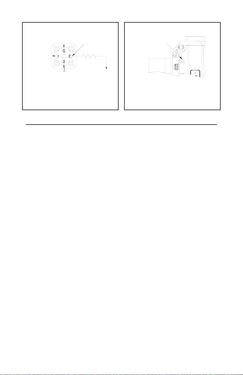
1-5 VDC Output Connections
Wiring Instructions (Refer to Illustrations 8 and 9 above):
1) Move the programmable jumper on the signal conditioning board
into the position closest to the meter’s outlet, as shown in
Illustration 9.
2) Connect the positive voltage (+17 to +35 VDC) to terminal #1 of
the din connector.
3) Connect terminal #2 of the DIN to the 1-5 VDC input of the
receiving device.
4) If the power source does not originate at the receiving device, a
wire will need to be connected between the negative side of the
voltage source and the signal ground of the receiving device.
5) If the transmitter is operating properly, the green LED on the
circuit board will illuminate dimly at zero flow and will increase in
intensity as flow rate increases.
Page 35 / Flow Transmitters
Illustration 8 Illustration 9
NO CONNECTION
ELECTRICAL CONNECTIONS - 1- 5 VDC
NO CONNECTION
249 OHMS
PIN #1
+17 - 35 VDC
PIN #2
1-5 VDC OUT
TO SIGNAL
GROUND
PROGRAMMABLE JUMPER
IN POSITION CLOSEST
TO METER OUTLET
JUMPER POSITION - 1- 5 VDC
Page 36
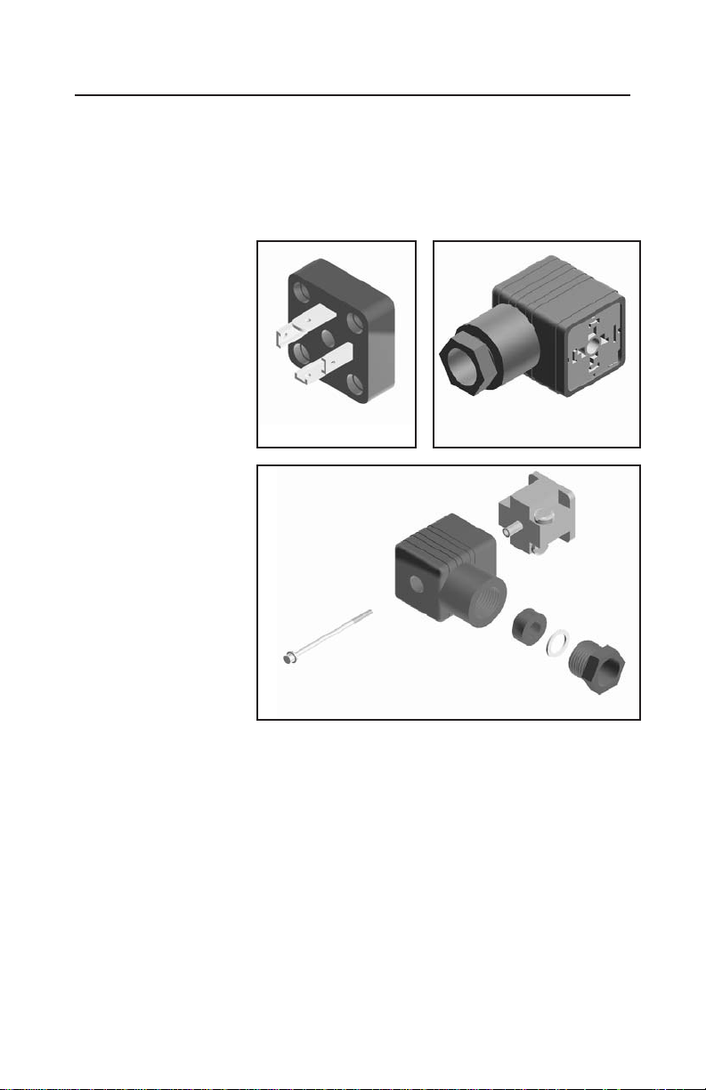
Connectors
Standard flow sensors are prewired with 4-wire Hirschmann-type DIN
connectors which consist of a male section as shown in Illustration 10
and a female section as shown in Illustration 11. In order to make the
user connections, the screw terminals located inside of the female
section must be accessed.
To open the female
section, first
remove the screw
and then lift the
connector portion
out of the casing by
inserting the head
of a screwdriver
into the slot marked
for that purpose.
Illustration 12
shows the disassembled female
section. The screw
terminal connections can be seen
on the piece located
at the far right side
of the illustration.
Alternate connectors are available on a custom basis. Nearly any
type of commercially available electrical connector may be installed
on an Omega Flow Transmitter. If an alternate connector is required,
please consult the Omega factory.
Page 36 / Flow Transmitters
Illustration 10 Illustration 11
Illustration 12
Page 37

User Adjustments
The 4-20 mA, 0-5V, and 0-2000 Hz square wave outputs on the
Omega Flow Transmitter are all factory calibrated. User adjustment
should be unnecessary and any adjustment of the potentiometer on
the signal conditioning board is strongly discouraged. If one of the
outputs does fall out of calibration, the following procedure may be
used to recalibrate the unit.
1) Turn off the flow through the system.
2) Connect between +12 and +35 VDC to pin 1 of the din connector.
Connect terminal 2 of the din connector to the negative terminal
of the DC supply.
3) Move the programmable jumper on the signal conditioning
board into the position closest to the sensor’s inlet, as shown in
Illustrations 5 and 7.
4) Connect the positive terminal of a voltmeter to pin 3 of the din
connector. Connect the negative terminal to pin 2 of the din
connector.
5) Gradually increase the flow through the system until the flow rate
indicated on the printed flow rate scale reaches full-scale (the
highest value printed on the scale).
6) Adjust the 0-5 VDC Span potentiometer until a reading of
5.00 VDC is obtained on the voltmeter.
7) Turn off the flow through the system and remove the voltmeter.
8) Move the programmable jumper on the signal conditioning board
into the position closest to the sensor’s outlet, as shown in
Illustrations 3 and 9.
9) Disconnect pin 1 of the din connector from the positive terminal of
the DC power supply.
10) Connect the positive terminal of an ammeter to the positive
terminal of the DC power supply. Connect the negative terminal
of the ammeter to pin 1 of the sensor’s din connector.
11) Adjust the 4-20 mA Offset potentiometer (See Illustration 1) until
a reading of 4.00 mA is obtained on the ammeter.
Page 37 / Flow Transmitters
Page 38

12) Gradually increase the flow through the system until the flow rate
indicated on the printed flow rate scale reaches full-scale (the
highest value printed on the scale).
13) Adjust the 4-20 mA span potentiometer (See Illustration 1) until
a reading of 20.00 mA is obtained on the ammeter.
14) Gradually decrease the flow through the system until a value
equal to 50% of full-scale is obtained on the sensor’s flow rate
scale. Verify a reading of between 11.92 and 12.08 mA.
Page 38 / Flow Transmitters
Trouble Shooting
Symptom Solution
The green LED does not
illuminate when power is
applied.
1) Re-check the wiring diagram for the
communication protocol that is being
used and verify that the wiring is correct.
2) Verify that the DC supply that is being
used is capable of producing at least
12 VDC.
3) Make sure that the cable that is
soldered to the din connector inside
of the sensor enclosure is plugged
into the connector opposite to the
programmable jumper.
The readings obtained from the
electronic output do not agree
with the readings shown on the
printed flow rate scale.
1) Make sure that the programmable
jumper is in the correct position for
the communication protocol that is
being used.
The green LED illuminates, but
no readings are obtained from
the sensor’s electronic output.
1) Re-check the wiring diagram for the
communication protocol that is being
used and verify that the wiring is correct.
2) Make sure that the cable from the sensor
assembly is plugged into the connect on
the signal conditioning board located
near the sensor inlet.
When the flow rate in the
systems changes, the follower
and electronic output do not
respond.
1) Remove the flow sensor from the
hydraulic systems and inspect the
intervals to see if anything has caused
them to become jammed. Make sure
that the 200 mesh, 74 micron filtration
requirement of the flow sensor is being
observed.
Page 39

WARRANTY/ DISCLAIMER
OMEGA ENGINEERING, INC. warrants this unit to be free of defects in materials and
workmanship for a period of 13 months from date of purchase. OMEGA’s WARRANTY adds an
additional one (1) month grace period to the normal one (1) year product warranty to cover
handling and shipping time. This ensures that OMEGA’s customers receive maximum
coverage on each product.
If the unit malfunctions, it must be returned to the factory for evaluation. OMEGA’s Customer
Service Department will issue an Authorized Return (AR) number immediately upon phone or
written request. Upon examination by OMEGA, if the unit is found to be defective, it will be
repaired or replaced at no charge. OMEGA’s WARRANTY does not apply to defects resulting
from any action of the purchaser, including but not limited to mishandling, improper interfacing,
operation outside of design limits, improper repair, or unauthorized modification. This
WARRANTY is VOID if the unit shows evidence of having been tampered with or shows evidence
of having been damaged as a result of excessive corrosion; or current, heat, moisture or vibration; improper specification; misapplication; misuse or other operating conditions outside of
OMEGA’s control. Components in which wear is not warranted, include but are not limited to
contact points, fuses, and triacs.
OMEGA is pleased to offer suggestions on the use of its various products. However,
OMEGA neither assumes responsibility for any omissions or errors nor assumes liability
for any damages that result from the use of its products in accordance with information
provided by OMEGA, either verbal or written. OMEGA warrants only that the parts
manufactured by the company will be as specified and free of defects. OMEGA MAKES
NO OTHER WARRANTIES OR REPRESENTATIONS OF ANY KIND WHATSOEVER,
EXPRESSED OR IMPLIED, EXCEPT THAT OF TITLE, AND ALL IMPLIED WARRANTIES
INCLUDING ANY WARRANTY OF MERCHANTABILITY AND FITNESS FOR A PARTICULAR
PURPOSE ARE HEREBY DISCLAIMED. LIMITATION OF LIABILITY: The remedies of purchaser set forth herein are exclusive, and the total liability of OMEGA with respect to this
order, whether based on contract, warranty, negligence, indemnification, strict liability or
otherwise, shall not exceed the purchase price of the component upon which liability is
based. In no event shall OMEGA be liable for consequential, incidental or special damages.
CONDITIONS: Equipment sold by OMEGA is not intended to be used, nor shall it be used: (1) as
a “Basic Component” under 10 CFR 21 (NRC), used in or with any nuclear installation or activity;
or (2) in medical applications or used on humans. Should any Product(s) be used in or with any
nuclear installation or activity, medical application, used on humans, or misused in any way,
OMEGA assumes no responsibility as set forth in our basic WARRANTY/ DISCLAIMER language,
and, additionally, purchaser will indemnify OMEGA and hold OMEGA harmless from any liability
or damage whatsoever arising out of the use of the Product(s) in such a manner.
RETURN REQUESTS/INQUIRIES
Direct all warranty and repair requests/inquiries to the OMEGA Customer Service Department.
BEFORE RETURNING ANY PRODUCT(S) TO OMEGA, PURCHASER MUST OBTAIN AN
AUTHORIZED RETURN (AR) NUMBER FROM OMEGA’S CUSTOMER SERVICE DEPARTMENT
(IN ORDER TO AVOID PROCESSING DELAYS). The assigned AR number should then be
marked on the outside of the return package and on any correspondence.
The purchaser is responsible for shipping charges, freight, insurance and proper packaging to
prevent breakage in transit.
FOR WARRANTY
RETURNS, please have
the following information available BEFORE
contacting OMEGA:
1. Purchase Order number under which
the product was PURCHASED,
2. Model and serial number of the product
under warranty, and
3. Repair instructions and/or specific
problems relative to the product.
FOR NON-WARRANTY REPAIRS,
consult
OMEGA for current repair charges. Have the
following information available BEFORE
contacting OMEGA:
1. Purchase Order number to cover the
COST of the repair,
2. Model and serial number of the
product, and
3. Repair instructions and/or specific problems
relative to the product.
OMEGA’s policy is to make running changes, not model changes, whenever an improvement is possible.
This affords our customers the latest in technology and engineering.
OMEGA is a registered trademark of OMEGA ENGINEERING, INC.
© Copyright 2005 OMEGA ENGINEERING, INC. All rights reserved. This document may not be copied, photocopied,
reproduced, translated, or reduced to any electronic medium or machine-readable form, in whole or in part, without
the prior written consent of OMEGA ENGINEERING, INC.
Page 40

Where Do I Find Everything I Need for
Process Measurement and Control?
OMEGA…Of Course!
Shop online at omega.com
TEMPERATURE
Thermocouple, RTD & Thermistor Probes, Connectors, Panels & Assemblies
Wire: Thermocouple, RTD & Thermistor
Calibrators & Ice Point References
Recorders, Controllers & Process Monitors
Infrared Pyrometers
PRESSURE, STRAIN AND FORCE
Transducers & Strain Gages
Load Cells & Pressure Gages
Displacement Transducers
Instrumentation & Accessories
FLOW/LEVEL
Rotameters, Gas Mass Flowmeters & Flow Computers
Air Velocity Indicators
Turbine/Paddlewheel Systems
Totalizers & Batch Controllers
pH/CONDUCTIVITY
pH Electrodes, Testers & Accessories
Benchtop/Laboratory Meters
Controllers, Calibrators, Simulators & Pumps
Industrial pH & Conductivity Equipment
DATA ACQUISITION
Data Acquisition & Engineering Software
Communications-Based Acquisition Systems
Plug-in Cards for Apple, IBM & Compatibles
Datalogging Systems
Recorders, Printers & Plotters
HEATERS
Heating Cable
Cartridge & Strip Heaters
Immersion & Band Heaters
Flexible Heaters
Laboratory Heaters
ENVIRONMENTAL
MONITORING AND CONTROL
Metering & Control Instrumentation
Refractometers
Pumps & Tubing
Air, Soil & Water Monitors
Industrial Water & Wastewater Treatment
pH, Conductivity & Dissolved Oxygen Instruments
M-2589/0405
 Loading...