

Page 1
MADE IN
24
20
16
12
8
4
GPM
WATER
90
80
60
40
20
LPM
®
User’s Guide
Shop online at
omega.com
e-mail: [email protected]
For latest product manuals:
omegamanual.info
®
FL-9000 and FL9000-AC
Flow Meter and Flow Alert Meter
Page 2

®
OMEGAnet®Online Service Internet e-mail
omega.com [email protected]
Servicing North America:
U.S.A.: Omega Engineering, Inc., One Omega Drive, P.O. Box 4047
ISO 9001 Certified Stamford, CT 06907-0047 USA
Canada: 976 Bergar
Laval (Quebec), H7L 5A1 Canada
Toll-Free: 1-800-826-6342 TEL: (514) 856-6928
FAX: (514) 856-6886 e-mail: [email protected]
For immediate technical or application assistance:
U.S.A. and Canada: Sales Service: 1-800-826-6342/1-800-TC-OMEGA
Customer Service: 1-800-622-2378/1-800-622-BEST
Engineering Service: 1-800-872-9436/1-800-USA-WHEN
Mexico/ En Español: 001 (203) 359-7803 FAX: 001 (203) 359-7807
Latin America: [email protected] e-mail: [email protected]
®
®
®
Servicing Europe:
Benelux: Managed by the United Kingdom Office
Czech Republic: Frystatska 184
France: Managed by the United Kingdom Office
Germany/Austria: Daimlerstrasse 26
United Kingdom: OMEGA Engineering Ltd.
ISO 9001 Certified
733 01 Karviná, Czech Republic
Toll-Free: 0800-1-66342 TEL: +420-59-6311899
FAX: +420-59-6311114 e-mail: [email protected]
Toll-Free: 0800 466 342 TEL: +33 (0) 161 37 29 00
FAX: +33 (0) 130 57 54 27 e-mail: [email protected]
D-75392 Deckenpfronn, Germany
Toll-Free: 0800 6397678 TEL: +49 (0) 7056 9398-0
FAX: +49 (0) 7056 9398-29 e-mail: [email protected]
One Omega Drive, River Bend Technology Centre, Northbank
Irlam, Manchester M44 5BD United Kingdom
Toll-Free: 0800-488-488 TEL: +44 (0) 161 777-6611
FAX: +44 (0) 161 777-6622 e-mail: [email protected]
It is the policy of OMEGA Engineering, Inc. to comply with all worldwide safety and EMC/EMI
regulations that apply. OMEGA is constantly pursuing certification of its products to the European New
Approach Directives. OMEGA will add the CE mark to every appropriate device upon certification.
The information contained in this document is believed to be correct, but OMEGA accepts no liability for any
errors it contains, and reserves the right to alter specifications without notice.
WARNING: These products are not designed for use in, and should not be used for, human applications.
Page 2
Page 3
Installation & Maintenance Instructions
I. INTRODUCTION
The FL9000 series fl ow meter is a rugged,
low-cost direct reading industrial class fl ow
meter that is simple to install. It can be
mounted (installed) in any position from
vertical to horizontal without costly fl ow
straighteners or other special plumbing.
Constructed of high impact polysulfone
plastic, the FL9000 product line offers
excellent structural integrity and chemical
compatibility with a wide range of industrial
chemicals.
FL9000 fl ow meters provide instantaneous,
direct-reading fl ow rate measurement
of liquids in closed piping systems. The
transparent polysulfone plastic body allows
visual inspection of the fl uid condition as
well as viewing of the internal fl ow indicator
relative to a calibrated fl ow scale. See
Figure 1.
FL9000 meters do not require electrical
connections for operation, and provide
measurement by creating a predictable
differential pressure across a sharpedged orifi ce that is located in the piston
assembly.
II. OPERATING PRINCIPLE
The FL9000 series fl ow meter is a piston-
type variable area fl ow meter that uses
a sharp-edged annular orifi ce, formed
between an open-centered piston and a
tapered metering cone. The piston is held
in a “no-fl ow” position at the base of the
cone by a precision retention spring. As
fl ow in the pipe increases, the differential
pressure correspondingly increases across
the piston orifi ce, and moves the piston/
fl ow indicator against the spring. The
greater the fl ow rate, the further the piston
moves along the tapered metering cone.
The fl ow rate is measured by viewing the
red indicator ring, mounted on the piston,
relative to a graduated fl ow scale located
on the transparent fl ow meter body. See
Figure 2.
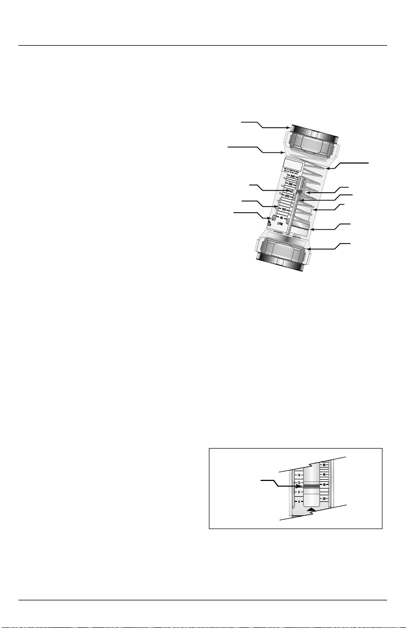
End Fitting
Body
Spring
Limit Indicator
Flow Scale
Magnet
(
Switching Models Only)
Metering Cone
Serrated Rail
Piston Assembly
Flow Indicator
Pressure Seal
Figure 1. Flow Meter
The unique design allows the FL9000
meter to be mounted in any orientation–
horizontal, vertical, upside down,
etc.–without sacrifi cing measurement
performance. Flow straighteners, located
in the inlet and outlet, allow the fl ow
meter to be less sensitive to turbulent
fl ow conditions. Liquid measurements are
provided in GPM (Gallons per Minute) and
LPM (Liters per Minute).
80
60
GPM
16
12
40
8
20
4
LPM
Flow Rat e
Indicator
Figure 2. Flow Rate Indicator
Page 3
Page 4
III. SPECIFICATIONS
Accuracy
• ±5% of full scale
Repeatability
• ±1%
Pressure Rating
• 325 PSI (22.4 bar) Maximum
• Meters with Type 1 PVC fitting subject to
normal PVC system ratings
Temperature Range
• +32 °F to +250 °F (0 °C to +121 °C)
• +32 °F to +140 °F (0 °C to + 60 °C) for
meters with Type 1 PVC fittings
Pressure Drop
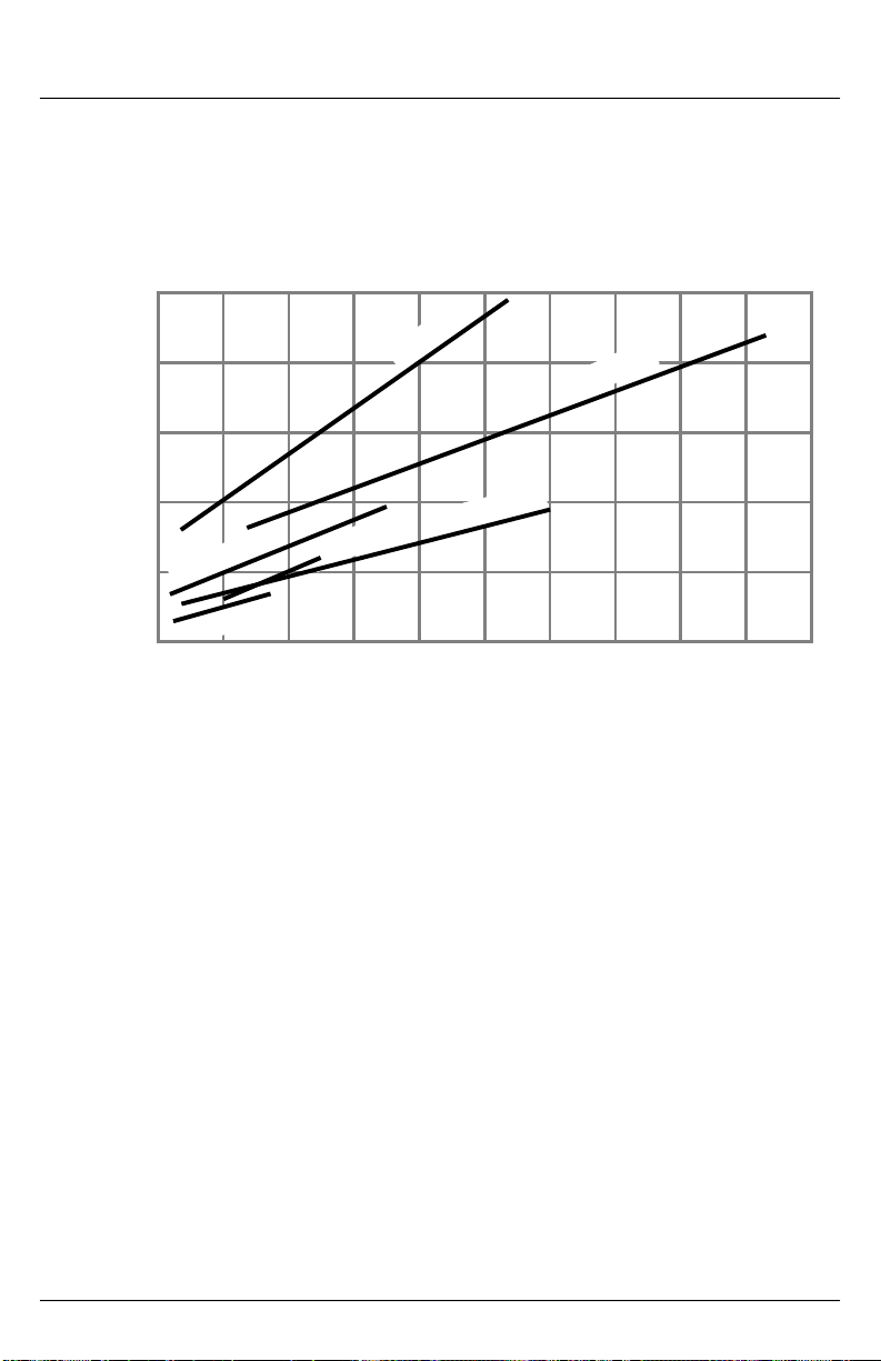
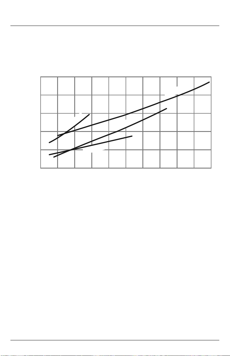
See Pressure Drop Charts on page 14
Fittings/Threads
• NPT ANSI/ASME B1.20.1
• BSPT ISOR7
• BSPP ISO228
Materials (wetted)
• Body
½", ¾" & 1" sizes
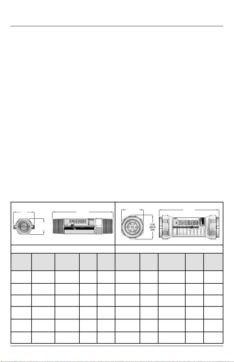
Dimensions
Installation & Maintenance Instructions
Polysulfone or Radel
1-½" & 2" sizes Radel
• Piston Polysulfone
• Cone
½", ¾" & 1" sizes Polysulfone or Radel
1-½" & 2" sizes Polysulfone
• Spring T300 Stainless Steel
• Retaining Rings PH15-7MO
Stainless Steel
• Seals Buna-N
• Indicator Ring Buna-N
• Magnet Strontium Ferrite
(switching units only)
• Fittings C360 Brass, PVC
or T303 Stainless Steel
Materials (non-wetted)
• Limit Indicator Polypropylene
• Scale Polyester
Material Compatibility
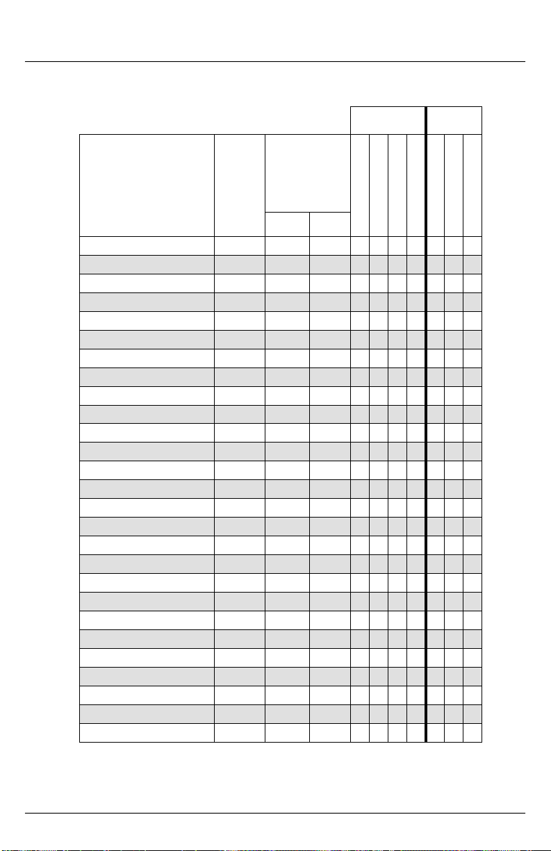
• See Fluid Selection Chart on page 13
Calibration Fluid
• Oil 0.876 specific gravity,
32 cSt viscosity
• Water 1.0 specific gravity,
1.0 cSt viscosity
®
®
®
1.78
(45.2)
1.37
(34.8)
BODY FLATS
LENGTH
LPM
2040608090
CAUTION
!
1. Only use Teflon tape to seal threaded fittings.
DO NOT use pipe dope.
2. DO NOT sweat fit adaptor fittings into a system
while mounted to the EZ-VIEW meter.
½", ¾" & 1" Sizes 1-½" & 2" Sizes
Size &
Type
½" NPTF
& BSPT
¾" NPTF
& BSPT
¾" &
1" Sweat
1" NPTF Polysulfone Male 5.25
1" Nominal PVC Socket Weld 8.46
1" NPTF PVC Male 8.86
Page 4
Material Connection Length
Brass & SS Female 7.75
Brass Male 8.25
Brass
Brass
Male
Sweat
in (mm)
(196.8)
(209.5)
7.75
(196.8)
(133.3)
(214.9)
(225.0)
W
®
Fitting
Flats
in (mm)
1.50
(38.1)
1.50
(38.1)
1.50
(38.1)
N/A 2" Socket
1.54
(39.1)
1.50
(38.1)
3.25 (82.5)
BODY FLATS
Size & Type Material Connection Length
1-½" NPTF
& BSPP
1-½" Socket
Weld
2" NPTF &
BSPP
Weld
-- -- -- -- --
-- -- -- -- --
Brass Female 8.72
PVC Socket Weld 12.72
Brass Female 8.72
PVC Socket Weld 11.48
LENGTH
in (mm)
(221.5)
(323.1)
(221.5)
(291.6)
Fitting
Flats
in (mm)
3.00
(76.2)
N/A
3.00
(76.2)
N/A
Page 5
Installation & Maintenance Instructions
IV. INSTALLATION
CAUTION
This unit should be installed and serviced
by technically qualifi ed personnel
trained in maintaining industrial class
fl ow instrumentation and processing
equipment.
CAUTION
Read instructions thoroughly before
installing the unit. If you have any
questions regarding product installation
or maintenance, call your local supplier
for more information.
Installation Recommendations
The fl ow meter is a simple device to
install. However, the following measures
are recommended for reliable, trouble-free
operation:
CAUTION
Liquid pipe sealants, PVC/CPVC primers
and PVC/CPVC cements contain solvents
that are not compatible with polysulfone
plastic. Allowing liquid pipe sealants to
contact the plastic fl ow meter will result
in weakening of the fl ow meter body
and potentially cause fracturing under
pressure.
Don’t - Allow liquid pipe sealant, PVC/
CPVC primer or PVC/CPVC cements to
come into contact with the plastic fl ow
meter. These contain solvents that are not
compatible with polysulfone plastic and will
result in the fl ow meter body weakening and
potentially fracturing under pressure. If a
pipe sealant is required, use of Tefl on
is recommended.
Don’t - Install the fl ow meter in piping
systems that are not aligned or properly
supported.
Don’t - Connect the fl ow meter male plastic
®
tape
NPT fi ttings to female metal NPT couplings.
Differences in coeffi cients of expansion
between metals and plastics can cause the
plastic fl ow meter body to crack. Utilize a
female-to- female plastic pipe coupling to
connect metal pipe to the plastic fl ow meter.
Don’t - Use pipe wrenches on the fl ow
meter body. To avoid scarring or otherwise
damaging the external surface, use an
open-end wrench on the integral hex fl ats
during installation.
Don’t - Subject the fl ow meter to back
pressure or back fl ow. The fl ow meter
will operate as a “leaky” check valve
when subjected to reverse fl ow, but can
be damaged if the reverse hydraulic
horsepower is too great.
Don’t - Install the fl ow meter on systems with
large degrees of particulate contamination.
Minimum fi ltration of 200 mesh (74 micron)
is recommended for trouble-free operation.
Don’t - Install O-ring seals that have not
been lubricated.
Piping (Plumbing)
CAUTION
To avoid unnecessary pipe fl exing that
could cause structural stress on the fl ow
meter body, independent support located
as near as possible to the inlet and outlet
of the meter should be used to isolate the
meter from the piping system. Failure to
provide this support could reduce the life
of the meter.
Piping should be properly aligned with the
meter inlet and outlet to minimize structural
stress on the plastic meter body. Special
attention should be given to this effort
if higher operational pressures and/or
temperatures are anticipated. Piping should
be fi rmly supported by external mounting
brackets, both upstream and downstream
from the meter to avoid any pipe fl exing that
could reduce the life of the meter.
1. If the fl ow meter inlet or outlet are to be
Page 5
Page 6
Installation & Maintenance Instructions
rigidly mounted, and the opposing port
is to be connected to a fl exible hose,
the end connected to the fl exible hose
MUST be rigidly mounted.
2. This unique design does not require
special plumbing or accessories to
stabilize turbulent fl ow. Flow meters can
be installed immediately adjacent to 90°
elbows or other components, providing
system design fl exibility.
3. A 200 mesh (74 micron) or better
fi ltration is required to assure reliable
performance.
Flow Direction
These meters only accept fl ow in one
direction. Make sure to align the Flow
Arrow, located on the bottom of the meter’s
fl ow scale, in the same direction as the
anticipated line fl ow. See Figure 3.
Mounting Orientation
The meter can be installed to operate in any
position.
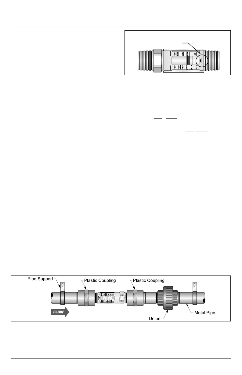
1" NPT Models (See Figure 4)
1. Apply a single layer of Tefl on® tape to the
male NPT threads of the fl ow meter.
2. Thread the fl ow meter inlet into a 1" NPT
plastic, female pipe coupling.
3. Thread the fl ow meter and coupling onto
the inlet pipe and hand tighten. Make
sure the fl ow direction arrow on the fl ow
meter corresponds with the system fl ow
direction. See Figure 3.
Flow Direction
Indicator
9080604020
242016
LPM
WATER
8
4
12
GPM
Figure 3. Flow Direction Indicator
4. Place an open-end wrench on the fl ow
meter body hex and place a pipe wrench
on the metal mating pipe. Tighten until
snug. DO NOT overtighten. Make
sure the fl ow meter scale is oriented for
convenient viewing. DO NOT back off/
unscrew fi ttings to rotate scale for better
viewing.
5. Thread a 1" NPT plastic pipe coupling to
the outlet connection of the fl ow meter.
Stack a pipe nipple and half of a pipe
union onto the pipe coupling. Tighten
the assembly as required.
6. Install the other half of the pipe union to
the outlet pipe and connect the union
halves together.
7. Piping should be supported and aligned
properly to avoid placing stress on the
fl ow meter body.
8. Slide the limit indicators to point to
appropriate positions on the fl ow meter
scale. To remove the limit indicators,
slide them fully towards the fl ow meter
outlet.
Page 6
Figure 4. 1" NPT Models Installation
Page 7
Installation & Maintenance Instructions
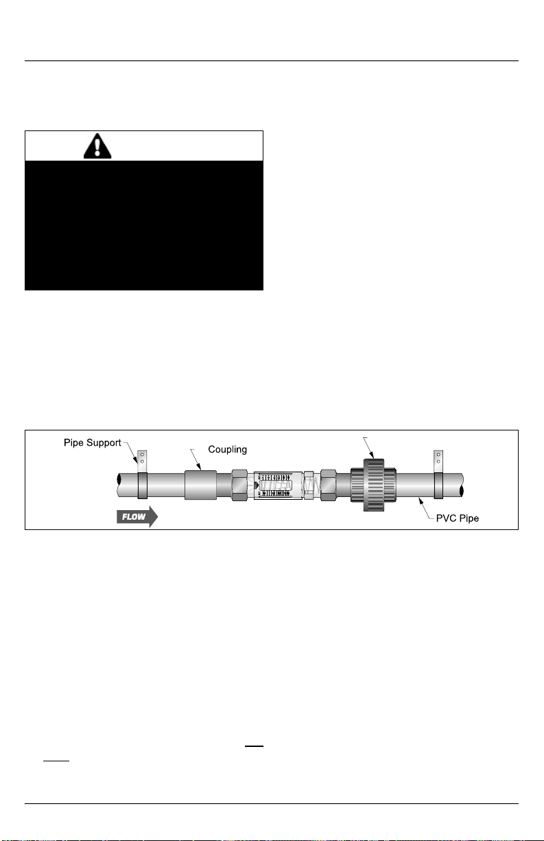
1", 1-½" and 2" PVC with Socket Weld Models (See Figure 5)
1. Remove the two end fi ttings from the
fl ow meter. Lubricate the O-rings and
install the fi ttings onto the fl ow meter.
CAUTION
Liquid pipe sealants, PVC/CPVC primers
and PVC/CPVC cements contain solvents
that are not compatible with polysulfone
plastic. Allowing liquid pipe sealants to
contact the plastic fl ow meter will result
in weakening of the fl ow meter body
and potentially cause fracturing under
pressure.
2. Prepare the fl ow meter PVC fi ttings and
PVC pipe couplings with PVC cleaner/
solvent.
3. Apply a thin layer of PVC glue to the
PVC fl ow meter fi ttings. Orient the meter
during curing to ensure that excessive
glue will not run into or onto the fl ow
meter. Connect all PVC glue joints by
inserting the pipes fully into their mating
components and twisting 1/8 turn to
guarantee adhesion. Allow suffi cient
drying time.
4. Using the method outlined in steps 2 &
3, apply half of the PVC union to the fl ow
meter outlet fi tting.
5. Install the other half of the PVC pipe
union to the outlet pipe.
6. Make sure the fl ow direction arrow on the
fl ow meter corresponds with the system
fl ow direction. See Figure 3 on page 4.
Lubricate the union O-ring and connect
the union together.
7. Piping should be supported and aligned
properly to avoid placing stress on the
fl ow meter body.
8. Slide the limit indicators to point to
appropriate positions on the fl ow meter
scale. To remove the limit indicators, slide
them fully towards the fl ow meter outlet.
1"
Figure 5. 1", 1-½" & 2" PVC Socket Weld Models Installation
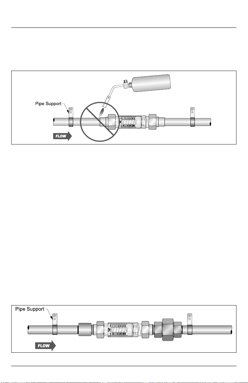
Brass Sweat Fitting Models (See Figure 6 on page 8)
1. Remove both brass fi ttings from the fl ow
meter inlet and outlet. Remove O-rings
from the fi ttings.
2. Apply solder fl ux to the fl ow meter brass
fi ttings and mating pipe surfaces.
3. Place the brass hex coupler onto the
pipe with the thread facing the fl ow
meter. Slide the brass sweat fi tting onto
the prepared pipe.
4. Sweat the fi ttings onto the pipe. DO
NOT apply heat to the brass fl ow meter
fi tting with the plastic fl ow meter body or
seals attached to the fi tting.
5. Repeat steps 3 & 4 for the other fl ow
meter fi tting. Allow fi ttings to cool.
6. Lubricate the two O-rings removed in step
1. Place the O-rings onto the brass fi ttings.
7. Place the fl ow meter in between the
two installed brass fi ttings. Make sure
the fl ow direction arrow on the fl ow
meter corresponds with the system
fl ow direction. See Figure 3 on page 6.
Thread the two brass hex couplers into
the fl ow meter body.
8. Rotate the fl ow meter body so the scale
can be conveniently viewed. Tighten
1" Union
Page 7
Page 8
Installation & Maintenance Instructions
the hex couplers. Typically, only hand
tightening is required.
9. Piping should be supported and aligned
properly to avoid placing stress on the
10. Slide the limit indicators to point to
appropriate positions on the fl ow meter
scale. To remove the limit indicators, slide
them fully towards the fl ow meter outlet.
fl ow meter body.
Figure 6. Brass Sweat Fitting Models Installation
All Models with Male, Metal or PVC Threaded End Fittings (See Figure 7)
1. Remove both fi ttings from the fl ow meter
inlet and outlet. Remove O-rings from
the fi ttings.
®
2. Apply Tefl on
tape to the male pipe thread
connections.
3. Place the brass or stainless steel hex
coupler onto the pipe with the threads
facing the fl ow meter.
4. Thread the fl ow meter fi ttings onto the
mating pipe.
5. Tighten fi ttings by placing an open-end
wrench onto the fi tting and a pipe wrench
onto the mating pipe.
6. Repeat steps 3-5 for the other fl ow meter
fi tting.
7. Lubricate the two O-rings removed
in step 1. Place the O-rings onto the
threaded fi ttings.
8. Place fl ow meter between the two
installed fi ttings. Make sure the fl ow
direction arrow on the fl ow meter
corresponds with the system fl ow
direction. See Figure 3 on page 4.
Thread the two hex couplers onto the
fl ow meter body.
9. Rotate the fl ow meter body such that
the scale can be conveniently viewed.
Tighten hex couplers. Typically, only
hand tightening is required.
10. Piping should be supported and aligned
properly to avoid placing stress on the
fl ow meter body.
11. Slide the limit indicators to point to
appropriate positions on the fl ow meter
scale. To remove the limit indicators,
slide them fully towards the fl ow meter
outlet.
Figure 7. All Models w/Male, Metal or PVC Threaded End Fittings Installation
Page 8
Page 9
Installation & Maintenance Instructions
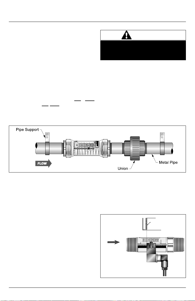
All Models with Female, Metal Threaded End Fittings (See Figure 8)
1. Apply Tefl on® tape to the male pipe thread
connections.
2. Thread the inlet of the fl ow meter onto
the appropriate pipe connection. Make
sure the fl ow direction arrow on the fl ow
meter corresponds with the system fl ow
direction. See Figure 3 on page 4.
3. Tighten fl ow meter connection by placing
an open-end wrench on the fl ow meter
metal connection adjacent to the pipe
that is being attached. Tighten until snug.
Make sure fl ow meter scale is oriented
for convenient viewing. DO NOT
overtighten. DO NOT back off/unscrew
to rotate scale for better viewing.
4. Install a union fi tting at the outlet end of
the fl ow meter.
Do not tighten the fl ow meter by wrenching
from the opposite fi tting, as the meter
body could crack.
5. Piping should be supported and aligned
properly to avoid placing stress on the
fl ow meter body.
6. Slide the limit indicators to point to
appropriate positions on the fl ow meter
scale. To remove the limit indicators,
slide them fully towards the fl ow meter
outlet.
CAUTION
Figure 8. All Models w/Female, Metal Threaded End Fittings Installation
V. FLOW-ALERT SWITCH OPTIONS
NOTE: All Flow-Alert switches are
magnetically triggered. It is not possible
to add a switch to the basic meter if it was
not originally ordered with the switching
magnet.
Flow-Alert Latching Limit Switch
The AC and DC powered Flow-Alert
modules consist of a relay circuit housed
in a sealed plastic enclosure. The modules
have a normally open, dry relay contact
that can be used to directly control alarms,
warning lights, relays, or interface to a PLC.
The relay will be latched on as the magnet
inside the fl ow meter passes by the module,
and remain latched on until the magnet
passes in the other direction, or power is
interrupted. See Figure 9. The setpoint is
adjustable from 0-100% of full scale. Flow
meters can be equipped with one latching
limit switch, either AC or DC.
On
Switch
Contacts
Off
LPM
FLOW DIRECTION
1. Only use Teflon tape to seal threaded fittings.
DO NOT use pipe dope.
2. DO NOT sweat fit adaptor fittings into a system
while mounted to the EZ-VIEW meter.
Figure 9. Latching Switches
3%
Deadband
0
2040608090
CAUTION
!
Full
Scale
Page 9
Page 10
Installation & Maintenance Instructions
Flow-Alert Reed Limit Switch
The reed switch Flow-Alert modules are
available in three forms: Form A (normally
open), Form B (normally closed), and Form
Switch
Contacts
C (single-pole, double throw).
Reed switches are housed in a sealed
plastic enclosure for environmental
protection. The reed switch modules do not
FLOW DIRECTION
1. Only use Teflon tape to seal threaded fittings.
DO NOT use pipe dope.
2. DO NOT sweat fit adaptor fittings into a system
while mounted to the EZ-VIEW meter.
provide a latching function like the AC and
DC powered units. When the magnet inside
the fl ow meter comes within proximity of the
Figure 10. Reed Switches
module, the reed switch will change state.
See Figure 10. The setpoint is adjustable
from 0-100% of full scale. Two reed switch
Flow-Alerts may be installed on a single fl ow
meter but one must be set for activation on
increasing fl ow and the second must be set
for activation on decreasing fl ow.
Switch Specifi cations
Specifi cations
Operating Voltage 115 VAC ± 10% 10-30 VDC N/A N/A N/A
Operating Current 25 mA maximum N/A N/A N/A
Contact Rating
Cable
Certifi cation N/A CE
Enclosure Rating NEMA 12 & 13 (IP65)
AC
LatchingDCLatching
1A @ 30 VDC
0.5A @ 125 VAC
Resistive Load
Not Included
N/A
Specifi cations
Watts Max
Voltage Max
Current Max
Reed Switch
Form A (NO)
10
200
1A
3 ft, 24 AWG
2 Conductor
PVC Jacket
15 - 25%
Of Scale
On
Off
0
LPM
2040608090
CAUTION
!
Reed Switch
Form B (NC)
5
175
.25A
3 ft, 20 AWG
2 Conductor
PVC Jacket
Full
Scale
Reed Switch
Form C
(SPDT)
3 ft, 24 AWG
3 Conductor
PVC Jacket
5
175
.25A
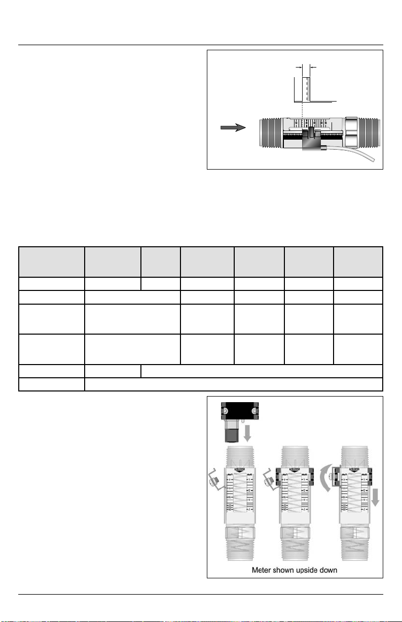
Flow-Alert Latching Switch Installation
1. Install one end of the vibration locking
kit onto the LPM side of the meter’s
serrated rail as shown in Figure
11. Install the switch by placing the
adjustment arm over the serrated rail
from the inlet end of the ½", ¾" and 1"
meters, or the outlet end of the 1-½" or 2"
meters. The direction of the connector
and cable assembly indicates whether
the switch will activate on increasing fl ow
(connector and cable pointing down).
See Figure 12 on page 9. Secure the
other end of the vibration locking kit and
tighten after positioning.
Page 10
Figure 11. Latching Switch Installation
Page 11
Installation & Maintenance Instructions
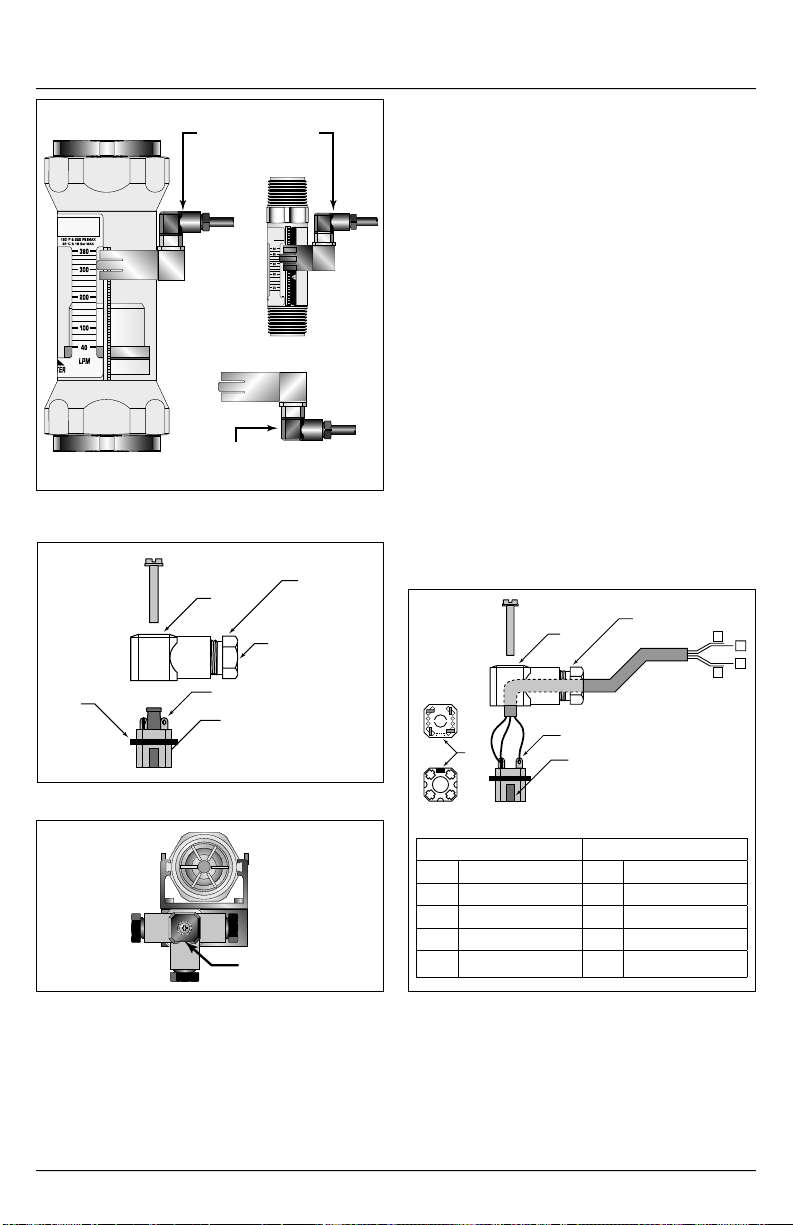
Switches Positioned for Activation
on Increasing Flow
90
80
60
CAUTION
40
!
20
LPM
1. Only use Teflon tape to seal threaded fittings.
DO NOT use pipe dope.
2. DO NOT sweat fit adaptor fittings into a system
while mounted to the EZ-VIEW meter.
Switch Positioned for Activation
on Decreasing Flow
Figure 12. Latching Switch Installation
Strain Relief Nut
Loosen Strain Relief
Nut and Run (4)
Wires In Here
Gasket
Body
Solder Lug
Polarity Pin
2. The connector has four solder lugs
labeled 1, 2, 3 and 4. Soldering wires to
the terminals fi rst requires disassembly
of the connector as shown in Figure 13.
The specifi c wiring pinouts for each style
latching switch are show in Figure 14.
NOTE: Before reassembly, it is
recommended to label each wire with
the corresponding lug position.
3. After securing wires to solder lugs,
determine which direction the body
of the connector should face. Before
snapping the connector into place, refer
to Figure 15.
4. After selecting direction A, B, or C, snap
connector back together, pull the excess
wire out of the strain relief, then tighten
the strain relief nut. Plug the connector
into the switch module and secure with
the screw provided.
Body
Top
View
32
3 2
1
4
1
4
Key
Solder Lug
2
Polarity Pin
14
Strain Relief Nut
1
2
3
4
Figure 13. Latching Switch Installation
CA
B
Polarity Pin
Figure 15. Polarity Pin
Bottom
View
DC Switch AC Switch
Pin Function Pin Function
1 Relay (NO) 1 Relay (NO)
2 DC+ 2 AC Supply
3 Relay Common 3 Relay Common
4 DC- 4 AC Supply
Figure 14. Latching Switch Installation
Page 11
Page 12
Installation & Maintenance Instructions
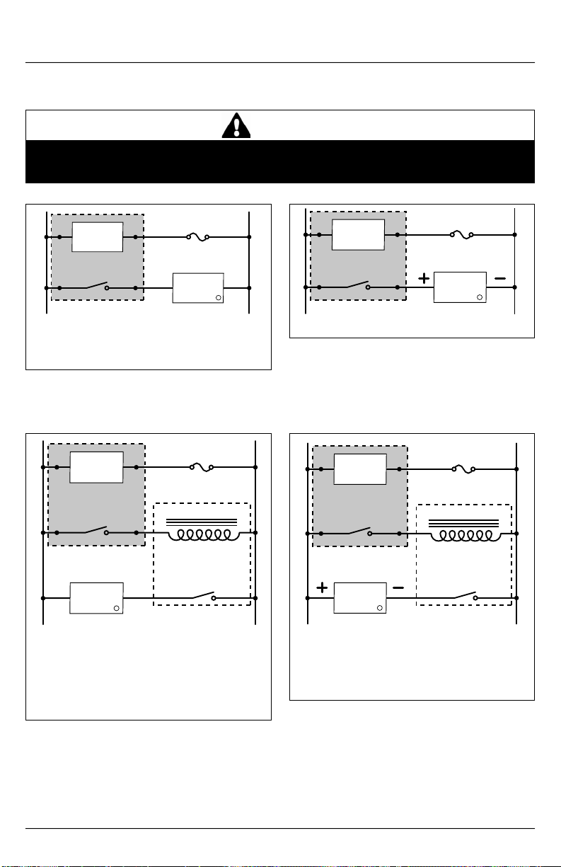
Flow-Alert Latching Switch AC Wiring Confi guration
WARNING
All wiring should be made in accordance with the National Electrical Code® and must
conform to any applicable state and local codes.
24
Flow
Circuit
AC Line
13
Switch Module
Contacts
Fuse
0.1 A
AC
Load
1
NOTE: Load must be within specifi ed contact
rating range.1A @ 30 VDC/500 mA @ 125 VAC.
Figure 16. AC Conventional
Connection
24
Flow
Circuit
13
AC Line
Switch Module
Contacts
AC
Load
2
Example shows a secondary (slave) relay with
a 115 VAC coil integrated with the AC switch
module. This combination allows switching of
loads up to the rating of the relay contacts.
NOTE: Load limited by relay contacts.
Figure 17. AC Conventional Secondary
Connections
Fuse
0.1 A
115 V Relay Coil
AC Relay Contact
Fuse
0.1 A
DC
AC Line
24
Flow
Circuit
13
10 - 30 VDC
Load
Switch Module
Contacts
Figure 18. DC Conventional Connection
Fuse
0.1 A
DC Relay Coil
AC Line
24
Flow
Circuit
13
Switch Module
10 - 30 VDC
Contacts
DC
Load
2
DC Relay Contact
Example shows a secondary (slave) relay with
a DC coil integrated with the DC switch module.
This combination allows switching of loads up to
the rating of the relay contacts.
NOTE: Load limited by relay contacts.
Figure 19. DC Conventional Secondary
Connections
1
DC Ground
DC Ground
Page 12
Page 13
Installation & Maintenance Instructions
FORM A
(Normally Open)
RED
BLACK
FORM B
(Normally Closed)
BLACK
WHITE
FORM C
BLACK
(Normally Closed)
WHITE
(Common)
RED
(Normally Open)
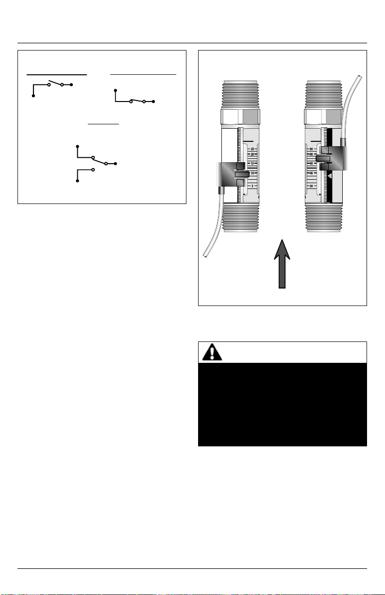
Figure 20. Form A, B & C
Flow-Alert Reed Switch Installation
1. Install the switch on the fl ow meter by
placing the adjustment arm over the
serrated rail from the inlet end of the
½", ¾", and 1" meters, or the outlet end
of the 1-½" and 2" meters. Each meter
will accept up to two reed switches and
the switch(es) for ½", ¾", and 1" meters
must be installed before the meter is
plumbed into the system.
2. Flow-Alert reed switches are available in
three confi gurations: Form A (normally
open), Form B (normally closed), and
Form C (SPDT). Wire color codes and
switch confi gurations are shown in
Figure 2 0.
Flow-Alert Reed Switch Adjustment
After the fl ow meter has been installed and
the switch wired, the fl ow rate at which the
switch will activate must be adjusted as
follows:
1. With the fl uid running through the meter,
gently move the switch adjustment
tab(s) outward until the switch body is
free to slide up or down on the serrated
rail. See Figure 21.
LEFT
SIDE
2200 SOUTH STREET RACINE, WI 53404 PHONE 1-800-FLOW-888 FAX 1-800-775-3179
GPM
25
20
15
10
5
RIGHT
SIDE
90
80
60
40
20
LPM
CAUTION
!
1. Only use Teflon tape to seal threaded fittings.
DO NOT use pipe dope.
2. DO NOT sweat fit adaptor fittings into a system
while mounted to the EZ-VIEW meter.
FLOW DIRECTION
Figure 21. Switch Orientation
WARNING FAIL-SAFE OPERATION
If the fl ow meter and switch are to be
installed in a critical application, be
sure the system is fail-safe. The switch
should be wired so any switch failure will
stop the system. Failure to fail-safe the
system may lead to system damage and/
or personal injury.
2. Move the switch into position until the
switch activates. See Figure 21.
3. Release the switch adjustment tab(s) to
set the switch position.
Page 13
Page 14

Installation & Maintenance Instructions
VI. MAINTENANCE
FL9000 Flow Meters are designed to
provide many years of service with little or
no maintenance requirements. Periodic
cleaning may be required.
• Clean the outside of the fl ow meter with
denatured alcohol or mild detergent and
warm water.
• Should the inside of the fl ow meter
become stained, it can be disassembled
for cleaning.
• Should the fl ow meter become jammed
with particulate, the meter will require
disassembly as described below. The
piston assembly should be pushed out
from the inlet side to the outlet side.
Clean the internal components and
reassemble.
Disassembly
NOTE: Models with a 1" body-it is necessary
to remove the spring retaining clip (located
at the fl ow meter outlet port).
NOTE: Models with a 2" body can be
serviced by removing the two end fi ttings,
then sliding the metering pin out from the
inlet, and removing the piston and spring
from the outlet.
1. Measure the insertion depth of the
retaining ring into the fl ow meter body
with a caliper or other measuring device.
2. Carefully remove the retaining clip with a
small, fl athead screwdriver.
3. Remove the spring and piston assembly.
4. Clean the inside of the fl ow meter body
and piston assembly with denatured
alcohol or mild detergent and water.
5. Reassemble the meter in reverse order
of disassembly. Install the retaining
ring to the depth measured in step 1.
Use a deep socket of approximately 0.9"
diameter and hand pressure to install the
retaining ring.
VI. APPENDIX
Fluid Correction
Standard Flow Scales
Standard liquid fl ow scales are calibrated
in GPM (Gallons per Minute) and LPM
(Liters per Minute) at 0.876 specifi c gravity
for petroleum-based fl uids, and 1.0 specifi c
gravity for water and water-based fl uids.
For fi eld conversion of the standard scale to
other fl uids, see Density Effect below.
Special Flow Scales
Special scales are available for liquids
in any measurement unit, and other fl uid
viscosities and/or specifi c gravities.
Viscosity Effect (SS/cSt)
The design utilizes a sharp-edged orifi ce
and biasing calibration spring that ensures
operating stability and accuracy over the
wide viscosity range common to many
fl uids. Generally, high fl ow models of each
meter size provide good accuracy over a
viscosity range of 40 to 500 SUS (4.2 to 108
cSt).
Density Effect (Specifi c Gravity)
Any fl uid density change from stated
standards has a proportional effect on meter
accuracy. Special scales can be supplied if
actual specifi c gravity decreases accuracy
beyond application limits. Corrections for
more or less dense fl uids can be made
to standard scales using the following
correction factor:
1.0
Specifi c Gravity
for water/water-based
meters
√
0.876
Specifi c Gravity
for petroleum-based
meters
√
Page 14
Page 15
Installation & Maintenance Instructions
Fluid Selection Chart
Correction
Fluid
Acetic Acid (Air Free) 1.06 0.909 0.971 RRCRNRR
Acetone 0.79 1.053 1.125 NRNRRNR
Alcohol, Butyl (Butanol) 0.83 1.027 1.089 RRRRCRR
Alcohol, Ethyl (Ethanol) 0.83 1.027 1.089 RRNRCRR
Ammonia 0.89 0.992 1.060 RRCRCRR
Benzene 0.69 1.127 1.204 NNNNRNN
Carbon Disulfi de 1.26 0.834 0.891 NRNRNNR
Castor Oil 0.97 0.950 1.015 CCRCRCC
Cotton Seed Oil 0.93 0.970 1.037 RRRRRNR
Ethylene Glycol 50/50 1.12 0.884 0.945 RRRRRRR
Freon II 1.46 0.774 0.828 NRNRRNR
Gasoline 0.70 1.119 1.195 RRRRRCR
Glycerin 1.26 0.834 0.891 RRRRRRR
Kerosene 0.82 1.033 1.104 RRRRRRR
Liquid Propane (LPG) 0.51 1.310 1.400 NRRRRRR
Mineral Oil 0.92 0.976 1.042 RRRRRRR
Naphtha 0.76 1.074 1.147 NRRRNNR
Perchloroethylene 1.62 0.735 0.786 NRRRNNR
Petroleum Oil 0.876 1.000 1.068 RRRRRRR
Phosphate Ester 1.18 0.862 0.921 NRNRRNR
Phosphate Ester Base 1.26 0.833 0.891 NRNRRNR
Phosphoric Acid (Air Free) 1.78 0.701 0.749 RNCNNRN
Sea Water 1.03 0.922 0.985 RNRNNRN
Synthetic Petroleum Base 1.00 0.936 1.000 RRRRCRR
Water 1.00 0.936 1.000 RRRRRRR
Water Glycol 50/50 1.07 0.950 0.967 RRRRRRR
Water-in-Oil 0.93 0.970 1.037 RRRRRRR
R - Recommended N - Not Recommended C - Consult Factory
Specifi c
Gravity
Factor of
Standard
Scales
Oil Water
Internal
Components
Polysulfone
T300 Stainless
Buna N
Fittings
PH157 MO Stainless
C360 Brass
PVC - Type 1
T303 Stainless
Page 15
Page 16
Pressure Drop Charts
½", ¾", 1" OIL & WATER METERS
10.00
Installation & Maintenance Instructions
8.00
6.00
4.00
2.00
PRESSURE DROP (PSID)
0
16 GPM
28 GPM
18 GPM
7 GPM
10 GPM
4 GPM
0 3 6 9 12 15 18 21 24 27 30
FLOW (GPM)
NOTE: The pressure drop curves are valid for fl uids with
density and viscosity similar to factory test fl uids. Fluids,
especially with higher viscosity than these test fl uids, will yield
a higher pressure drop through the fl ow meter and piping
system per a given fl ow volume.
Note: A system must have adequate fl uidic horsepower
available to move the system fl uid at a prescribed rate at a
pressure adequate to overcome all pressure reducing devices
- including the fl ow meter.
Page 16
Page 17
2.5
Installation & Maintenance Instructions
1½", 2" OIL & WATER METERS
2.0
100 GPM
1.5
25 GPM
75 GPM
1.0
0.5
50 GPM
PRESSURE DROP (PSID)
0
0 10.0 20.0 30.0 40.0 50.0 60.0 70.0 80.0 90.0 100.0
FLOW (GPM)
Page 17
Page 18

Installation & Maintenance Instructions
NOTES
Page 18
Page 19

WARRANTY/ DISCLAIMER
OMEGA ENGINEERING, INC. warrants this unit to be free of defects in materials and workmanship for a
period of 13 months from date of purchase. OMEGA’s WARRANTY adds an additional one (1) month
grace period to the normal one (1) year product warranty to cover handling and shipping time. This
ensures that OMEGA’s customers receive maximum coverage on each product.
If the unit malfunctions, it must be returned to the factory for evaluation. OMEGA’s Customer Service
Department will issue an Authorized Return (AR) number immediately upon phone or written request.
Upon examination by OMEGA, if the unit is found to be defective, it will be repaired or replaced at no
charge. OMEGA’s WARRANTY does not apply to defects resulting from any action of the purchaser,
including but not limited to mishandling, improper interfacing, operation outside of design limits,
improper repair, or unauthorized modification. This WARRANTY is VOID if the unit shows evidence of
having been tampered with or shows evidence of having been damaged as a result of excessive corrosion;
or current, heat, moisture or vibration; improper specification; misapplication; misuse or other operating
conditions outside of OMEGA’s control. Components in which wear is not warranted, include but are not
limited to contact points, fuses, and triacs.
OMEGA is pleased to offer suggestions on the use of its various products. However,
OMEGA neither assumes responsibility for any omissions or errors nor assumes liability for any
damages that result from the use of its products in accordance with information provided by
OMEGA, either verbal or written. OMEGA warrants only that the parts manufactured by the
company will be as specified and free of defects. OMEGA MAKES NO OTHER WARRANTIES OR
REPRESENTATIONS OF ANY KIND WHATSOEVER, EXPRESSED OR IMPLIED, EXCEPT THAT OF
TITLE, AND ALL IMPLIED WARRANTIES INCLUDING ANY WARRANTY OF MERCHANTABILITY
AND FITNESS FOR A PARTICULAR PURPOSE ARE HEREBY DISCLAIMED. LIMITATION OF
LIABILITY: The remedies of purchaser set forth herein are exclusive, and the total liability of
OMEGA with respect to this order, whether based on contract, warranty, negligence,
indemnification, strict liability or otherwise, shall not exceed the purchase price of the
component upon which liability is based. In no event shall OMEGA be liable for
consequential, incidental or special damages.
CONDITIONS: Equipment sold by OMEGA is not intended to be used, nor shall it be used: (1) as a “Basic
Component” under 10 CFR 21 (NRC), used in or with any nuclear installation or activity; or (2) in medical
applications or used on humans. Should any Product(s) be used in or with any nuclear installation or
activity, medical application, used on humans, or misused in any way, OMEGA assumes no responsibility
as set forth in our basic WARRANTY/D ISCLAIMER language, and, additionally, purchaser will indemnify
OMEGA and hold OMEGA harmless from any liability or damage whatsoever arising out of the use of the
Product(s) in such a manner.
RETURN REQUESTS/INQUIRIES
Direct all warranty and repair requests/inquiries to the OMEGA Customer Service Department. BEFORE
RETURNING ANY PRODUCT(S) TO OMEGA, PURCHASER MUST OBTAIN AN AUTHORIZED RETURN
(AR) NUMBER FROM OMEGA’S CUSTOMER SERVICE DEPARTMENT (IN ORDER TO AVOID
PROCESSING DELAYS). The assigned AR number should then be marked on the outside of the return
package and on any correspondence.
The purchaser is responsible for shipping charges, freight, insurance and proper packaging to prevent
breakage in transit.
FOR WARRANTY
following information available BEFORE
contacting OMEGA:
1. Purchase Order number under which the product
was PURCHASED,
2. Model and serial number of the product under
warranty, and
3. Repair instructions and/or specific problems
relative to the product.
OMEGA’s policy is to make running changes, not model changes, whenever an improvement is possible. This affords
our customers the latest in technology and engineering.
OMEGA is a registered trademark of OMEGA ENGINEERING, INC.
© Copyright 2012 OMEGA ENGINEERING, INC. All rights reserved. This document may not be copied, photocopied,
reproduced, translated, or reduced to any electronic medium or machine-readable form, in whole or in part, without the
prior written consent of OMEGA ENGINEERING, INC.
RETURNS, please have the
FOR NON-WARRANTY REPAIRS,
for current repair charges. Have the following
information available BEFORE contacting OMEGA:
1. Purchase Order number to cover the COST
of the repair,
2. Model and serial number of the product, and
3. Repair instructions and/or specific problems
relative to the product.
consult OMEGA
Page 19
Page 20
Where Do I Find Everything I Need for
Process Measurement and Control?
OMEGA…Of Course!
Shop online at omega.com
TEMPERATURE
Thermocouple, RTD & Thermistor Probes, Connectors, Panels & Assemblies
Wire: Thermocouple, RTD & Thermistor
Calibrators & Ice Point References
Recorders, Controllers & Process Monitors
Infrared Pyrometers
PRESSURE, STRAIN AND FORCE
Transducers & Strain Gages
Load Cells & Pressure Gages
Displacement Transducers
Instrumentation & Accessories
FLOW/LEVEL
Rotameters, Gas Mass Flowmeters & Flow Computers
Air Velocity Indicators
Turbine/Paddlewheel Systems
Totalizers & Batch Controllers
pH/CONDUCTIVITY
pH Electrodes, Testers & Accessories
Benchtop/Laboratory Meters
Controllers, Calibrators, Simulators & Pumps
Industrial pH & Conductivity Equipment
SM
DATA ACQUISITION
Data Acquisition & Engineering Software
Communications-Based Acquisition Systems
Plug-in Cards for Apple, IBM & Compatibles
Data Logging Systems
Recorders, Printers & Plotters
HEATERS
Heating Cable
Cartridge & Strip Heaters
Immersion & Band Heaters
Flexible Heaters
Laboratory Heaters
ENVIRONMENTAL
MONITORING AND CONTROL
Metering & Control Instrumentation
Refractometers
Pumps & Tubing
Air, Soil & Water Monitors
Industrial Water & Wastewater Treatment
pH, Conductivity & Dissolved Oxygen Instruments
M-1174/0312
 Loading...