

Page 1
®
®
®
®
®
®
®
An OMEGA Technologies Company
®
®
®
®
®
®
®
®
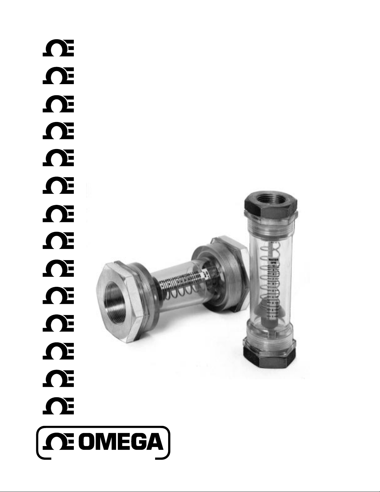
FL500 Series
In-Line Flowmeters
and Switch Kits
Operator’s Manual
1
Page 2

omega.com
TM
OMEGA
®
OMEGAnetSMOn-Line Service Internet e-mail
http://www.omega.com [email protected]
USA:
ISO 9001 Certified
Canada:
For immediate technical or application assistance:
USA and Canada:
Mexico and
Latin America:
Benelux:
Czech Republic:
France:
Germany/Austria:
United Kingdom:
ISO 9002 Certified
Servicing North America:
One Omega Drive, Box 4047
Stamford, CT 06907-0047
Tel: (203) 359-1660 FAX: (203) 359-7700
e-mail: [email protected]
976 Bergar
Laval (Quebec) H7L 5A1
Tel: (514) 856-6928 FAX: (514) 856-6886
e-mail: [email protected]
Sales Service: 1-800-826-6342 / 1-800-TC-OMEGA
Customer Service: 1-800-622-2378 / 1-800-622-BEST
Engineering Service: 1-800-872-9436 / 1-800-USA-WHEN
TELEX: 996404 EASYLINK: 62968934 CABLE: OMEGA
Tel: (95) 800-TC-OMEGA
En Espan˜ol: (203) 359-1660 ext: 2203 e-mail: [email protected]
SM
FAX: (95) 203-359-7807
SM
SM
SM
Servicing Europe:
Postbus 8034, 1180 LA Amstelveen, The Netherlands
Tel: (31) 20 6418405 FAX: (31) 20 6434643
Toll Free in Benelux: 06 0993344
e-mail: [email protected]
Ostravska 767, 733 01 Karvina
Tel: 42 (69) 6311899 FAX: 42 (69) 6311114
e-mail: [email protected]
9, rue Denis Papin, 78190 Trappes
Tel: 33 0130-621-400 FAX: 33 0130-699-120
Toll Free in France: 05-4-06342
e-mail: [email protected]
Daimlerstrasse 26, D-75392 Deckenpfronn, Germany
Tel: 49 (07056) 3017 FAX: 49 (07056) 8540
Toll Free in Germany: 0130 11 21 66
e-mail: [email protected]
25 Swannington Road, P.O. Box 7, Omega Drive,
Broughton Astley, Leicestershire, Irlam, Manchester,
LE9 6TU, England M44 5EX, England
Tel: 44 (1455) 285520 Tel: 44 (161) 777-6611
FAX: 44 (1455) 283912 FAX: 44 (161) 777-6622
Toll Free in England: 0800-488-488
e-mail: [email protected]
It is the policy of OMEGA to comply with all worldwide safety and EMC/EMI regulations that
apply. OMEGA is constantly pursuing certification of its products to the European New Approach
Directives. OMEGA will add the CE mark to every appropriate device upon certification.
The information contained in this document is believed to be correct but OMEGA Engineering, Inc. accepts
no liability for any errors it contains, and reserves the right to alter specifications without notice.
WARNING: These products are not designed for use in, and should not be used for, patient connected applications.
2
Page 3
®
ENGINEERING, INC.
P. O. Box 4047, Stamford, CT 06907
FL-500 Series In-Line Flowmeters
and Switch Kits
OUTLET
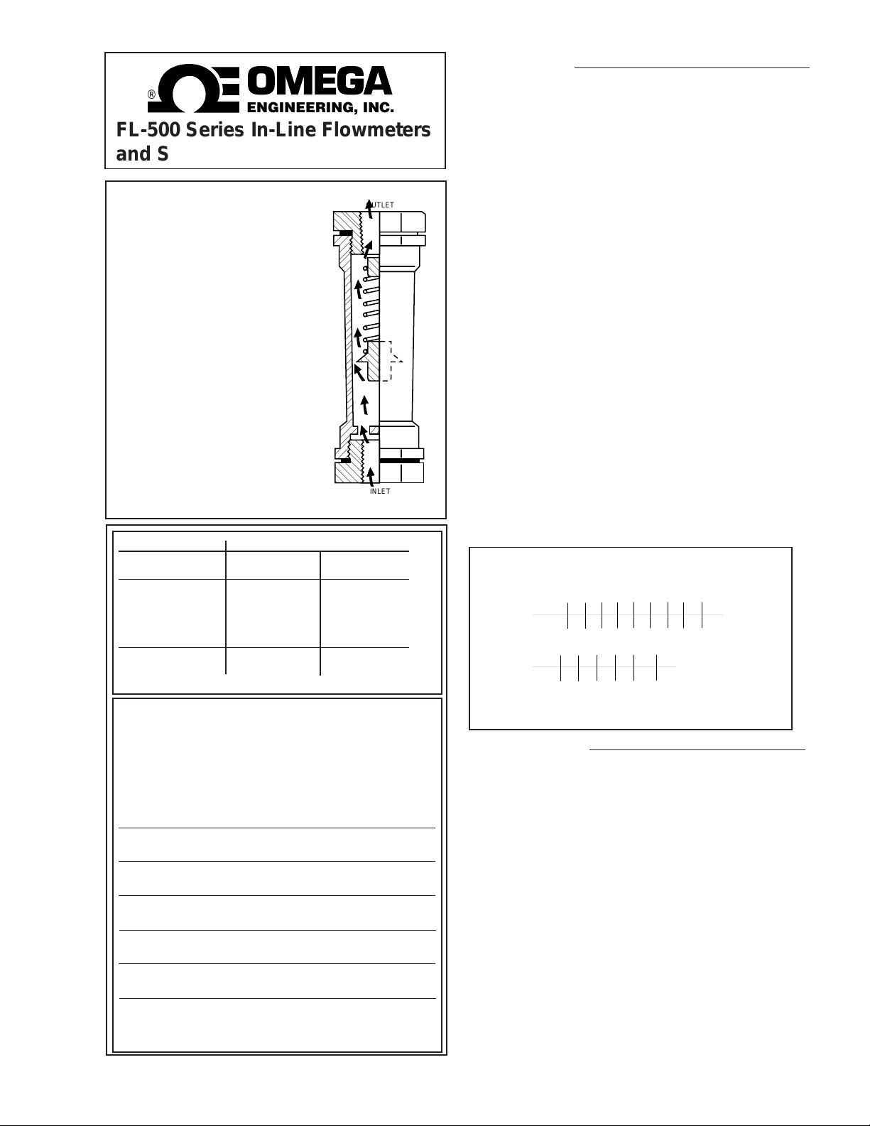
HOW IT WORKS
Fluid enters at end marked “IN” and
Installation
Inlet and outlet ends are marked on the flow meter body,
and an arrow on the printed scale indicates flow direction.
Insite flow meters can be mounted in any convenient
orientation (vertical, horizontal or anything in-between)
without affecting performance. The end fittings are connected to the plastic body with O-ring sealed straight
threads and don't need to be highly torqued to prevent
leakage. These fittings accept pipe with tapered threads
(NPT). Teflon tape should be used on the pipe threads and
standard torques applied, to make leak-free connections.
Put your wrench only on the end fitting when piping on.
Do not apply wrenches on the plastic body alone when
connecting to pipe.
forces the piston to move with it,
against spring pressure, enough to
pass given flow around piston
periphery. The knife edge of the
piston is visible through the
transparent housing; its position
under the printed scale gives the
flow rate.
Flow tube is PVC or polysulphone plastic
FLUID Temp. Max. Pressure
Liquid Air
(oF) (oC) PSIG kPa PSIG kPa
PVC
70 21 200 1379 100 690
100 38 100 690 50 345
125 52 75 517 35 241
150 65 50 345 25 172
POLYSULPHONE
230 110 250 1724 125 862
(Minimum temperature: -20 oF.)
INLET
SELECTION T ABLE
Each of the models carries scales for all media
shown
Maximum Flow Rates
Model Water Air
No. 90 PSI
FL-505 5 gpm 50 scfm
20 lpm 1400 slpm
FL-510 10 gpm 90 scfm
38 lpm 2500 slpm
FL-515 15 gpm 135 scfm
55 lpm 3900 slpm
FL-530 30 gpm 300 scfm
110 lpm 8000 slpm
FL-540 40 gpm 400 scfm
150 lpm 11000 slpm
FL-550 50 gpm 500 scfm
200 lpm 14000 slpm
Many users find that a disconnect fitting, installed upstream
of the flow meter, makes for easier removal of the flow
meter, for cleaning internals. Control valves should be
installed downstream of the flow meters.
Two scales are provided. One for liquid and one for air/
nitrogen gasses. Air/nitrogen gas meters are calibrated in
SCFM. The air/nitrogen scale is calibrated at 90 PSI
pressure and 70oF temperature. If the flow meter is used
with air at pressures and/or temperatures that differ from the
above, correction factors can be applied to a 90-psi air scale
readings to get correct SCFM values. See Tables.
High pressure air vented to atmosphere through the Insite
flow meter may result in erratic readings. When used to
measure high pressure air, it is recommended that a vent
valve be installed downstream of the flow meter.
Correction factors when monitoring air flow at other
than 90 PSI at 70°F
TABLE 1 PRESSURE
PSIG 10 20 30 40 50 60 70 80 90 100
Factor .49 .58 .65 .72 .79 .84 .90 .95 1.00 1.05
TABLE 2 TEMPERATURE
Temp°F 30 50 70 90 120 150
Factor 1.04 1.02 1.00 0.98 0.96 0.93
When operating at a pressure other than 90 PSIG multiply
the applicable factor to the SCFM reading on the tube for
corrected SCFM reading.
Maintenance
Normally, the only servicing required is a periodic cleaning
of the tube and three internal parts. Use wrenches on the
end fittings to remove the flow meter from the line. Do not
apply wrenches to the plastic body alone when
breaking pipe connections.
With the flow meter out of the line, completely remove the
end fitting from the outlet end of the tube. Use a bent wire
of other hook to grab the plastic shaft, piston and spring
and remove from tube. Inspect all parts for damage. The
interior of the tube can be swabbed out, and the parts
wiped off, with a soft dry cloth. If dirt or residue cannot be
removed with a dry cloth, use water and a mild nonabrasive soap. DO NOT USE SOLVENT OF ANY KIND.
Replace any worn or damaged parts.
When reassembling the flow meter, be sure the piston is
installed as shown in the drawing. Don’t put in upside
down. Inspect O-rings for damage and replace if
necessary.
3
Page 4
For Electric Signalling
Model FL-505, FL-510, and FL-515 flow meters can be
equipped with one or two electric switches so that any flow
rate within the range of the
meter can be made to
trigger a signal (or signals).
Switch settings are easily
adjusted. They are
supplied in kit form for
installation in the field.
Order No. FL-500-RI.
Model FL-530, FL-540 and
FL-550 require switch kit
#FL-500-R2.
Each switch kit consists of a
ring shaped ceramic
magnet that fits around the
flow meter
proximity switch in a
housing that clamps to
the body of the flow
meter. As the magnet moves with the piston, its field
trips the proximity switch. An adjustment screw
changes the actuation point by moving the switch.
8 Watts @ 120 VAC/100 VDC. DO NOT EXCEED
300 MILLIAMPS BELOW 26 VAC/26VDC. Switch
has three wires: Black for normally open, blue for
normally closed, and white for common.
piston, and a
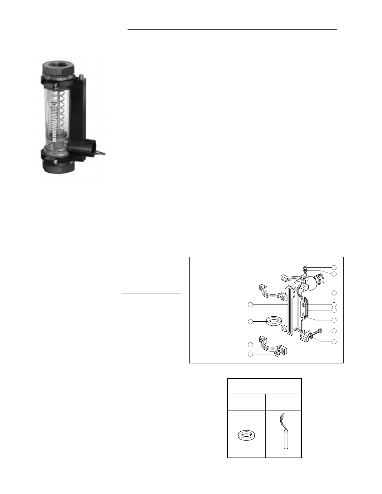
NOTE: There is no “wrong orientation” of the switch
housing. If you are installing two switch housings, they can
both be oriented the same way, as in the photo, or one “up”
and the other “down”. Install to suit your needs in wiring
and switch adjustment.
SETTING THE SWITCH POINTS
With flow meter installed:
Simply adjust the amount of flow to move the piston to the
level on the indicator where a switch signal is desired, then
turn the switch adjustment screw until switch actuates.
(Switch moves toward the adjustment screw head as you
turn it clockwise. Use an ohmmeter to determine actuation.) Repeat for second switch, if you are using two
switches.
With flow meter NOT installed:
Simulate flow by pushing the eraser-end of a pencil (or a
similar tool) through the inlet end of the tube, contacting the
float, and moving it against the spring pressure until the
knife edge of the float is at the desired reading on the
scale. (If your unit has a 1/2 in. pipe fitting, remove it to
gain better access.) Then, turn the switch adjustment
screw till the switch actuates. (Switch moves toward the
adjustment screw head as you turn it clockwise. Use an
ohmmeter to determine actuation.) Repeat for a second
switch, if you are using two switches.
When connecting the switch wires, leave enough lead
length (as a pigtail) to allow full travel of the switch.
NOTE: Switch has a 25% of full scale operating
band. Within the band, the switch activates. Above
and below the band, the switch deactivates. Thus,
one switch can be used as a deviation alarm.
SWITCH INSTALLATION
Step 1. Install the magnet. You must disassemble the flow
meter to do this. Follow instructions found under the
heading “Maintenance” on page 3. Remove piston from the
shaft and place the magnet between piston and spring.
Be sure that the piston is installed as in the drawing,
and the spring is seated on the magnet and piston.
Insert into tube and replace outlet end fittings.
Step 2. Install the foam gasket. It has an adhesive on one
side, covered with a protective paper. Peel off and press
the gasket firmly into place on the switch housing.
Step 3. Install the switch housing on the flow meter body.
(A) If you are installing only one switch, push the
capscrews through the switch housing tabs, and thread
them into the half-collars, as shown. Use the washers
provided. The nuts may be discarded.
(B) If you are installing two switches, match up the tabs on
the two switch housings and push the capscrews through
both collar tabs. Put the nuts on the threaded ends of the
capscrews and tighten. Use the washers provided. (The
half-collars and extra magnet may be discarded.)
Insite Switch
SWITCH PARTS
Parts Description
DESCRIPTION
1. Housing
2. Gasket
3. Magnet
4. Half-collars (2)
5. Capscrews (4)
6. Capscrew nuts (4)
7. Switch
8. Switch carrier
9. Adjustment screw
10. O-ring (2)
11. Retainer clip
12. Lockwashers (4)
FL-500 SERIES SWITCH
Replacement Parts
REPLACEMENT PARTS
MAGNET (ONLY)
Part # 1122
2
3
4
6
INSITE Switch
SWITCH (ONLY)
Part # 1127
11
10
1
7
8
9
5
12
4
Page 5
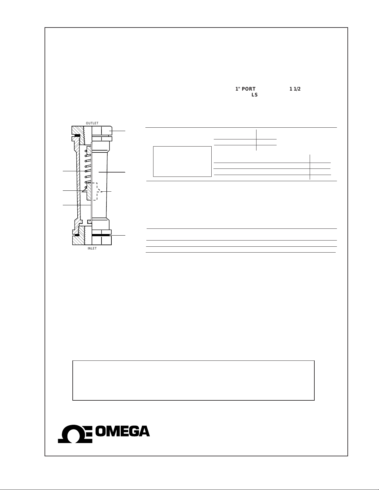
Replacement Parts
OUTLET
1
4
1
5
1
6
PISTON
1" PORT 1 1/2 " PORT
MODELS MODELS
FL-505 FL-530
FL-510 FL-540
FL-515 FL-550
DESCRIPTION PART NO. PART NO.
2
2
1. Flow tube PVC Polysulphone
Max reading, GPM scale: 5 1158-AS 1119-AS
10 1159-AS 1116-AS
When ordering replacement flow tubes verify
correct material of
1
1
construction marked
clearly on the old scale.
15 1160-AS 1117-AS
PVC Polysulphone
20 1147-AS 1173-AS
30 1148-AS 1174-AS
40 1149-AS 1175-AS
50 1150-AS 1176-AS
2. End Fittings (2 req'd)
Aluminum 1194-8 1196-12
Brass (Std.) 1193-8 1195-12
316 St. Steel 1188-8 476-12
PVC 1191-8 477-12
3
INLET
Viton (brown) 1112 396
4. Spring (316 S.S.) 1115 1115
5. Piston (PVC) 1105 1105
3. O-rings (2 req'd)
3
6. Shaft (316 S.S)
and Guide (PVC) 1103 1139
DIMENSIONS
Models FL-505 thru FL-515 are 7 inches long, 2 inches across the wrench flats.
Models FL-530 thru FL-550 are 7 inches long, 3 inches across the wrench flats.
®
ENGINEERING, INC.
P. O. Box 4047, Stamford, CT 06907
Copyright 1996 OMEGA ENGINEERING, INC.
All rights reserved including illustrations. Nothing
in this manual may be reproduced in any manner,
either wholly or in part for any purpose whatsoever
without written permission from OMEGA
ENGINEERING, INC.
5
Page 6

WARRANTY/DISCLAIMER
USA
MADE
IN
OMEGA ENGINEERING, INC. warrants this unit to be free of defects in materials and workmanship for a
period of 13 months from date of purchase. OMEGA Warranty adds an additional one (1) month grace
period to the normal one (1) year product warranty to cover handling and shipping time. This
ensures that OMEGA’s customers receive maximum coverage on each product.
If the unit should malfunction, it must be returned to the factory for evaluation. OMEGA’s Customer
Service Department will issue an Authorized Return (AR) number immediately upon phone or written
request. Upon examination by OMEGA, if the unit is found to be defective it will be repaired or replaced at
no charge. OMEGA’s WARRANTY does not apply to defects resulting from any action of the purchaser,
including but not limited to mishandling, improper interfacing, operation outside of design limits,
improper repair, or unauthorized modification. This WARRANTY is VOID if the unit shows evidence of
having been tampered with or shows evidence of being damaged as a result of excessive corrosion; or
current, heat, moisture or vibration; improper specification; misapplication; misuse or other operating
conditions outside of OMEGA’s control. Components which wear are not warranted, including but not
limited to contact points, fuses, and triacs.
OMEGA is pleased to offer suggestions on the use of its various products. However,
OMEGA neither assumes responsibility for any omissions or errors nor assumes liability for any
damages that result from the use of its products in accordance with information provided by
OMEGA, either verbal or written. OMEGA warrants only that the parts manufactured by it will be
as specified and free of defects. OMEGA MAKES NO OTHER WARRANTIES OR
REPRESENTATIONS OF ANY KIND WHATSOEVER, EXPRESSED OR IMPLIED, EXCEPT THAT OF
TITLE, AND ALL IMPLIED WARRANTIES INCLUDING ANY WARRANTY OF MERCHANTABILITY
AND FITNESS FOR A PARTICULAR PURPOSE ARE HEREBY DISCLAIMED. LIMITATION OF
LIABILITY: The remedies of purchaser set forth herein are exclusive and the total liability of
OMEGA with respect to this order, whether based on contract, warranty, negligence,
indemnification, strict liability or otherwise, shall not exceed the purchase price of the
component upon which liability is based. In no event shall OMEGA be liable for
consequential, incidental or special damages.
CONDITIONS: Equipment sold by OMEGA is not intended to be used, nor shall it be used: (1) as a “Basic
Component” under 10 CFR 21 (NRC), used in or with any nuclear installation or activity; or (2) in medical
applications or used on humans. Should any Product(s) be used in or with any nuclear installation or
activity, medical application, used on humans, or misused in any way, OMEGA assumes no responsibility
as set forth in our basic WARRANTY/ DISCLAIMER language, and additionally, purchaser will indemnify
OMEGA and hold OMEGA harmless from any liability or damage whatsoever arising out of the use of the
Product(s) in such a manner.
RETURN REQUESTS / INQUIRIES
Direct all warranty and repair requests/inquiries to the OMEGA Customer Service Department. BEFORE
RETURNING ANY PRODUCT(S) TO OMEGA, PURCHASER MUST OBTAIN AN AUTHORIZED RETURN
(AR) NUMBER FROM OMEGA’S CUSTOMER SERVICE DEPARTMENT (IN ORDER TO AVOID
PROCESSING DELAYS). The assigned AR number should then be marked on the outside of the return
package and on any correspondence.
The purchaser is responsible for shipping charges, freight, insurance and proper packaging to prevent
breakage in transit.
FOR W
following information available BEFORE
contacting OMEGA:
1. P.O. number under which the product was
2. Model and serial number of the product under
3. Repair instructions and/or specific problems
OMEGA’s policy is to make running changes, not model changes, whenever an improvement is possible. This affords
our customers the latest in technology and engineering.
OMEGA is a registered trademark of OMEGA ENGINEERING, INC.
© Copyright 1996 OMEGA ENGINEERING, INC. All rights reserved. This document may not be copied, photocopied,
reproduced, translated, or reduced to any electronic medium or machine-readable form, in whole or in part, without prior
written consent of OMEGA ENGINEERING, INC.
ARRANTY RETURNS, please have the
PURCHASED,
warranty, and
relative to the product.
FOR NON-WARRANTY REPAIRS,
consult OMEGA
for current repair charges. Have the following
information available BEFORE contacting OMEGA:
1. P.O. number to cover the COST
of the repair,
2. Model and serial number of product, and
3. Repair instructions and/or specific problems
relative to the product.
6
Page 7

Where Do I Find Everything I Need for
Process Measurement and Control?
OMEGA…Of Course!
TEMPERATURE
MU
Thermocouple, RTD & Thermistor Probes, Connectors, Panels & Assemblies
MU
Wire: Thermocouple, RTD & Thermistor
MU
Calibrators & Ice Point References
MU
Recorders, Controllers & Process Monitors
MU
Infrared Pyrometers
PRESSURE, STRAIN AND FORCE
MU
Transducers & Strain Gauges
MU
Load Cells & Pressure Gauges
MU
Displacement Transducers
MU
Instrumentation & Accessories
FLOW/LEVEL
MU
Rotameters, Gas Mass Flowmeters & Flow Computers
MU
Air Velocity Indicators
MU
Turbine/Paddlewheel Systems
MU
Totalizers & Batch Controllers
pH/CONDUCTIVITY
MU
pH Electrodes, Testers & Accessories
MU
Benchtop/Laboratory Meters
MU
Controllers, Calibrators, Simulators & Pumps
MU
Industrial pH & Conductivity Equipment
DATA ACQUISITION
MU
Data Acquisition & Engineering Software
MU
Communications-Based Acquisition Systems
MU
Plug-in Cards for Apple, IBM & Compatibles
MU
Datalogging Systems
MU
Recorders, Printers & Plotters
HEATERS
MU
Heating Cable
MU
Cartridge & Strip Heaters
MU
Immersion & Band Heaters
MU
Flexible Heaters
MU
Laboratory Heaters
ENVIRONMENTAL
MONITORING AND CONTROL
MU
Metering & Control Instrumentation
MU
Refractometers
MU
Pumps & Tubing
MU
Air, Soil & Water Monitors
MU
Industrial Water & Wastewater Treatment
MU
pH, Conductivity & Dissolved Oxygen Instruments
M2473/0796
7
Page 8

MANUAL M-2473/0896
FL500MAN 200.1M 10/96
8
 Loading...