

Page 1
OMEGAnet®Online Service Internet e-mail
omega.com [email protected]
Servicing North America:
C
U.S.A.: One Omega Drive, Box 4047
SO 9001 Certified
I
C
anada:
Stamford, CT 06907-0047
el: (203) 359-1660
T
FAX: (203) 359-7700
e-mail: [email protected]
76 Bergar
9
Laval (Quebec) H7L 5A1, Canada
Tel: (514) 856-6928
FAX: (514) 856-6886
e-mail: [email protected]
For immediate technical or application assistance:
U.S.A. and Canada: Sales Service: 1-800-826-6342/1-800-TC-OMEGA
Customer Service: 1-800-622-2378/1-800-622-BEST
Engineering Service: 1-800-872-9436/1-800-USA-WHEN
Mexico: En Espan˜ol: (001) 203-359-7803
AX: (001) 203-359-7807
F
-mail:[email protected]
It is the policy of OMEGA Engineering, Inc. to comply with all worldwide safety and EMC/EMI regulations that apply. OMEGA is constantly pursuing certification of its
roducts to the European New Approach Directives. OMEGA will add the CE mark to every appropriate device upon certification.
p
he information contained in this document is believed to be correct, but OMEGA accepts no liability for any errors it contains, and reserves the right to alter specifications without notice.
T
WARNING: These products are not designed for use in, and should not be used for, human applications.
®
®
®
zech Republic:
G
ermany/Austria:
United Kingdom: O
ISO 9002 Certified Northbank, Irlam, Manchester
Servicing Europe:
Frystatska 184, 733 01 Karviná, Czech Republic
Tel: +420 (0)59 6311899
FAX: +420 (0)59 6311114
Toll Free: 0800-1-66342
e-mail: [email protected]
Daimlerstrasse 26, D-75392 Deckenpfronn, Germany
Tel: +49 (0)7056 9398-0
FAX: +49 (0)7056 9398-29
Toll Free in Germany: 0800 639 7678
e-mail: [email protected]
ne Omega Drive, River Bend Technology Centre
M44 5BD United Kingdom
Tel: +44 (0)161 777 6611
AX: +44 (0)161 777 6622
F
Toll Free in United Kingdom: 0800-488-488
e-mail: [email protected]
WARRANTY/DISCLAIMER
OMEGA ENGINEERING, INC. warrants this unit to be free of defects in materials and workmanship for a period of 13 months from date of purchase.
OMEGA’s WARRANTY adds an additional one (1) month grace period to the normal one (1) year product warranty to cover handling and
shipping time. This ensures that OMEGA’s customers receive maximum coverage on each product.
If the unit malfunctions, it must be returned to the factory for evaluation. OMEGA’s Customer Service Department will issue an Authorized Return (AR)
number immediately upon phone or written request. Upon examination by OMEGA, if the unit is found to be defective, it will be repaired or replaced
at no charge. OMEGA’s WARRANTY does not apply to defects resulting from any action of the purchaser, including but not limited to mishandling,
improper interfacing, operation outside of design limits, improper repair, or unauthorized modification. This WARRANTY is VOID if the unit shows
evidence of having been tampered with or shows evidence of having been damaged as a result of excessive corrosion; or current, heat, moisture or
vibration; improper specification; misapplication; misuse or other operating conditions outside of OMEGA’s control. Components in which wear is not
warranted, include but are not limited to contact points, fuses, and triacs.
OMEGA is pleased to offer suggestions on the use of its various products. However, OMEGA neither assumes responsibility for any
omissions or errors nor assumes liability for any damages that result from the use of its products in accordance with information provided
by OMEGA, either verbal or written. OMEGA warrants only that the parts manufactured by the company will be as specified and free of
defects. OMEGA MAKES NO OTHER WARRANTIES OR REPRESENTATIONS OF ANY KIND WHATSOEVER, EXPRESSED OR IMPLIED, EXCEPT
THAT OF TITLE, AND ALL IMPLIED WARRANTIES INCLUDING ANY WARRANTY OF MERCHANTABILITY AND FITNESS FOR A PARTICULAR
PURPOSE ARE HEREBY DISCLAIMED. LIMITATION OF LIABILITY: The remedies of purchaser set forth herein are exclusive, and the total
liability of OMEGA with respect to this order, whether based on contract, warranty, negligence, indemnification, strict liability or otherwise,
shall not exceed the purchase price of the component upon which liability is based. In no event shall OMEGA be liable for consequential,
incidental or special damages.
CONDITIONS: Equipment sold by OMEGA is not intended to be used, nor shall it be used: (1) as a “Basic Component” under 10 CFR 21 (NRC), used in
or with any nuclear installation or activity; or (2) in medical applications or used on humans. Should any Product(s) be used in or with any nuclear
installation or activity, medical application, used on humans, or misused in any way, OMEGA assumes no responsibility as set forth in our basic
WARRANTY/ DISCLAIMER language, and, additionally, purchaser will indemnify OMEGA and hold OMEGA harmless from any liability or damage
whatsoever arising out of the use of the Product(s) in such a manner.
Direct all warranty and repair requests/inquiries to the OMEGA Customer Service Department. BEFORE RETURNING ANY PRODUCT(S) TO
RETURN REQUESTS/INQUIRIES
OMEGA, PURCHASER MUST OBTAIN AN AUTHORIZED RETURN (AR) NUMBER FROM OMEGA’S CUSTOMER SERVICE DEPARTMENT (IN ORDER
TO AVOID PROCES SING DELAYS). The assigned AR num ber shoul d then be marked on the outside of the return package and o n any
correspondence.
The purchaser is responsible for shipping charges, freight, insurance and proper packaging to prevent breakage in transit.
FOR WARRANTY
available BEFORE contacting OMEGA:
1. Purchase Order number under which the product was PURCHASED,
2. Model and serial number of the product under warranty, and
3. Repair instructions and/or specific problems relative to the product.
OMEGA’s policy is to make running changes, not model changes, whenever an improvement is possible. This affords our customers the latest in technology and
engineering. OMEGA is a registered trademark of OMEGA ENGINEERING, INC.
© Copyright 2007 OMEGA ENGINEERING, INC. All rights reserved. This document may not be copied, photocopied, reproduced, translated, or reduced to any electronic
medium or machine-readable form, in whole or in part, without the prior written consent of OMEGA ENGINEERING, INC.
RETURNS, please have the following information
FOR NON-WARRANTY REPAIRS,
consult OMEGA for current repair charges.
Have the following information available BEFORE contacting OMEGA:
1. Purchase Order number to cover the COST of the repair,
2. Model and serial number of the product, and
3. Repair instructions and/or specific problems relative to the product.
Page 2
FL-1200 Series
High Flow Rate Purge Rotometers
INSTRUCTION
SHEET
M0362/1200
Shop online at: omega.com e-mail: [email protected]
For latest product manuals: omegamanual.info
DESCRIPTION
The FL-1200 Flowmeters are variable area, glass tube,
flowrate indicating meters. The basic elements are a tapered
glass metering tube and a metering float. Features include
quick and simple removal or installation of the tube and float
while the meter remains in the process piping.
RECEIPT OF EQUIPMENT
When the equipment is received, the outside packing case
should be checked for any damage incurred during shipment.
If the packing case is damaged, the local carrier should be
notified at once regarding his liability.
UNPACKING
Carefully unpack the meter and inspect it for any damage
that may have occurred during shipment. The flowmeters are
shipped completely assembled and tested. It should not be
necessary to tighten or adjust any of the parts when it is
received.
RETURN SHIPMENT
Do not return any assembly without an authorized return
(AR) number from OMEGA Customer Service Department
(203) 359-1660.
INSTALLATION
The flowmeter should be mounted within 6° of the true
vertical. The inlet connection to the flowmeter is in the bottom
end fitting. The connections are normally horizontal, female
NPT. Be sure that the piping is adequately supported to
prevent undue strain on the meter. Both end fittings of the
flowmeter may be rotated in 90° increments. To rotate the end
fittings simply remove the side plates and tube and rotate the
end fitting to the desired location. When the meter is
reassembled, the side plates and endfittings are self-aligning.
OPERATION
CAUTION
Do not operate this instrument in excess of specifications.
After the flowmeter has been installed in the flow system, it is
ready for operation. A built-in needle control valve may be
provided to control the flow through flowmeter. These control
valves are designed for fine control. Excessive tightening may
damage the valve seat and limit its effectiveness as a control
valve. If tight shut-off is required, it is recommended that a
separate shut-off valve be installed in the line immediately
before the flowmeter.
DISASSEMBLY AND CLEANING
It is recommended the user periodically inspect the tube and
float, and clean if necessary. Dirt or foreign materials
adhering to the tube and float may cause inaccuracy and
sticking of the float. The metering tube (Borosilicate glass)
and related parts may be ultrasonically cleaned or cleaned
with any solvent which does not attack glass. To disassemble,
use the following procedures:
1. Remove the plastic safety shield.
2. Loosen the seal spindle or jack screw by turning it
counterclockwise with a 5/32" hex wrench. The tube may
now be canted out of the meter housing.
3. When cleaning Series FL-1200 meters, it is recommended
the spring float stops and float be removed to prevent the
stops and float from accidently failing out of the tube
during handling, and possibly causing damage to the float.
4. Packing seats and packing inserts now may be removed.
5. With the metering tube out, the seal spindle or jack screw
may be rotated clockwise for removal. it should not be
necessary to remove the seal spindle unless the “O” Ring
which seals the spindle requires replacement. The“O” Ring
may be used as long as it is not torn or distorted.
6. The needle control valve assembly may be removed by
turning the valve body counter-clockwise, The valve seat,
stem and packing then may be removed easily from the
valve body f or cleaning or replacement.
SPECIFICATIONS
SCALES
LENGTH: 65 mm
GRADUATIONS: Direct reading in gpm water or
scfm air
RATINGS
PRESSURE: 200 PSIG maximum
TEMPERATURE: 250°F maximum. Fluid temperatures
below 32°F will cause
frosting of the glass metering tube.
CONNECTIONS: Horizontal female, 3/8" NPT
ACCURACY: Conforms to ISA R. P. 16.1,
Specifications 10-S-10 ±10% full scale
REPEATABILITY: ±0.5% of full scale
DIMENSIONS: H: 8.44" x W: 1. 5" x D: 4.56"
CONSTRUCTION
METERING TUBE: Borosilicate Glass
FLOAT: 316 Stainless Steel
FLOAT STOPS: Stainless Steel
END FITTINGS &
TUBE RETAINING
ADAPTOR: Chrome plated brass, 316 stainless
steel
SIDE PLATES: Chrome plated brass
PACKING MATERIAL: O-Rings: Buna-N w/Brass, Viton
w/Stn Stl:
Packing: Neoprene®w/Brass, Viton
w/Stn StI.
®
Page 3
REASSEMBLY PROCEDURE
7
14
8
4
15
12
6
6
6
13
11
9
2
14
13
15
5
1
31
16
47
32
12
29
27
28
30
(Refer to parts diagram.)
. Use the reverse of steps 1 through 6 of the disassembly
1
rocedure to reassemble the meter.
P
2. When replacing the packing seats in the flowmeter body
be sure the packing inserts are approximately 1/16" above
the top of the packing seat. Also be certain the tube seats
firmly on the packing seats and does not overlap onto the
end block.
3. The seal spindle serves to radially compress the tube seat
gasket and exert a uniform pressure on the metering tube
to prevent any possibility of leakage. Do not overtighten
the seal spindle.
4. After the flowmeter has been reassembled, it is important
that it be hydrostatically tested at a liquid pressure of 300
psi at room temperature.
CAUTION
Hydrostatic testing should be performed only by trained
and qualified personnel or serious damage could result.
PARTS LIST
When ordering parts, please specify: SERIAL NUMBER,
flowmeter Model Number, Part Number if available, and if
known, specify materials of construction.
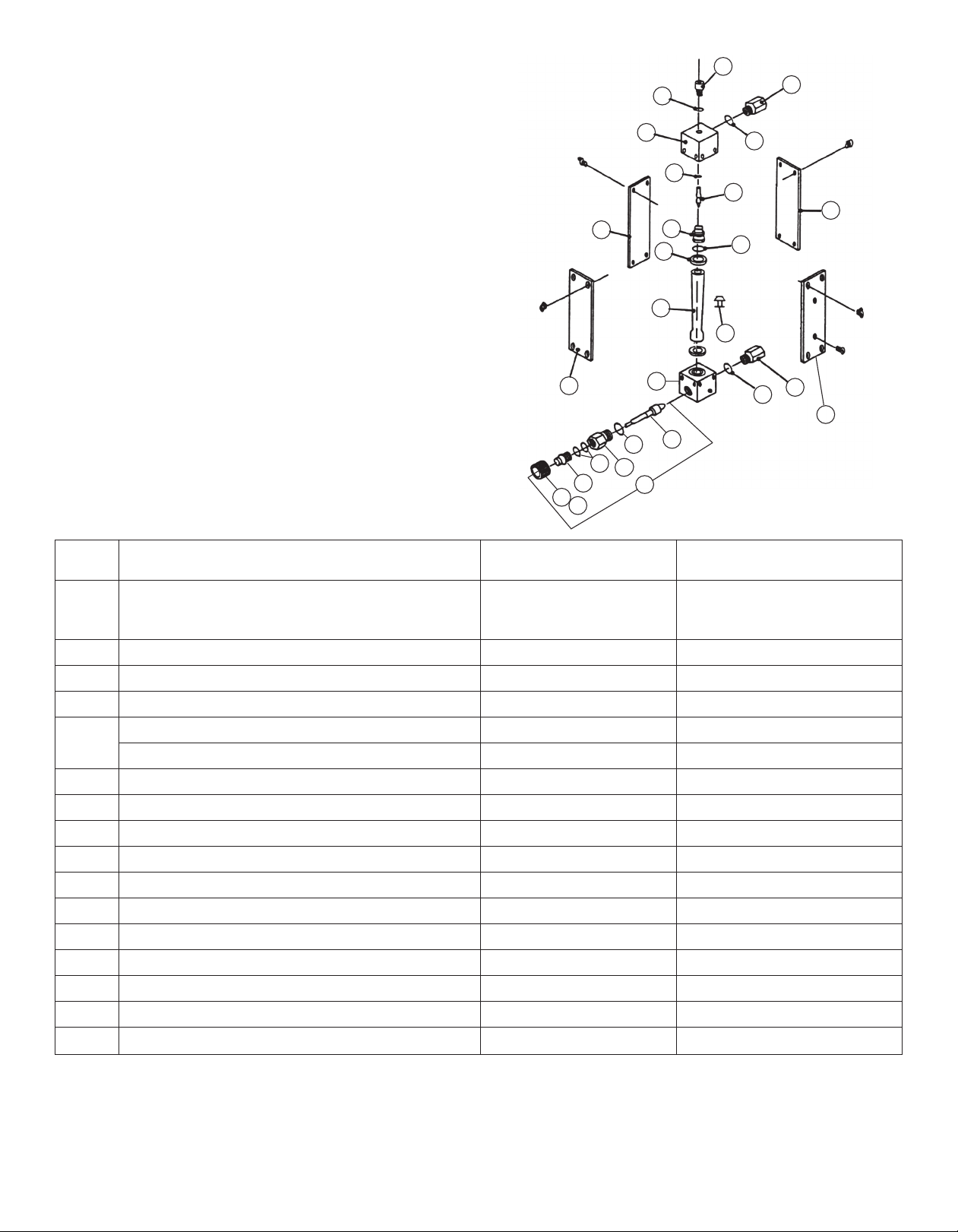
FL-1200 Series Part Drawing
ITEM DESCRIPTION
PART NUMBER MATERIAL
1 Metering Tube Assembly, Metering Tube (Std. or per S/N Standard, or Direct Etched
Direct Etched) 316 Stainless Steel Float,
Neoprene Packing, Stainless Steel Spring Stops
2 Float per S/N Stainless Steel
3 Spring Float Stops per S/N Stainless Steel
4 End Fitting (Outlet) A-325-G-001 Brass or Stainless Steel
*5 End Fitting (Inlet - Use Without Valve) A-325-J-006 Brass or Stainless Steel
End Fitting (Inlet - Use With Valve) A-325-H-002 Brass or Stainless Steel
6 Jack-Screw Assembly S-817-Z-009 Brass or Stainless Steel
7 Jack-Screw Nut A-618-J-005 Brass or Stainless Steel
8 O-Ring F-375-B-905 Buna-N, Kel-F, Viton
9 O-Ring (major) F-375-B -211 Buna-N, Kel-F, Viton
10 O-Ring (minor) F-375-B-010 Buna-N, Kel-F, Viton
11 Inlet and Outlet Packing A-589-B-043 Neoprene or Teflon
12 Window Shield (2) with Screws A-794-A-012-NOA Clear Plexiglas
13 Sideplate (2) with Screws A-614-A-008-FCG Aluminum
14 Adapter (2) 3/8” NPT A-014-C-023 Brass or Stainless Steel
15 O-Ring F-375-B-908 Buna-N, Kel-F
16 Needle Valve Assembly T-947-B-110 Brass or Stainless Steel
* End fitting only, valve not included. See item 16 when ordering valve.
WARNING Glass metering tubes are designed for operation up to the maximum operating pressures and temperatures as
specified herein. Due to the inherent brittle characteristics of glass and conditions beyond our control, tube breakage could
result below specified operating conditions. Possible glass tube breakage represents a potential hazard to operating personnel;
therefore, operator protection should be supplied where operating pressures may exceed 50 psig. A safety shield constructed of
1/2 inch acrylic plastic may be used or the glass tube meter may be replaced with an all metal (armored) meter.
2
Page 4
CAPACITIES
MAXIMUM FLOWRATE
Pressure Drop Pressure Drop
Part No. Water (gpm) Inches W.C. Inches W.C.
w/o Valve w/Valve
FL-1210 .08-.8 12.6 13.6
FL-1211 .15 -1.5 22.2 27.0
L-1212 .25-2.5 61.0 85.2
F
FL-1213 .35-3.5 88.7 121.0
FL-1214 .5-5.0 172.0 238.0
Pressure Drop Pressure Drop
Part No. Air (scfm) Inches W.C. Inches W.C.
W/o valve W/Valve
FL-1201 .34-3.4 14.34 15.5
FL-1202 .6-6.0 25.34 30.8
FL-1203 1.2 -12.0 69.34 97.3
FL-1204 1.5 -15.0 101.34 138.3
WARNING
FLOWMETER OPERATION
If the inlet and outlet valves adjacent to the flowmeter are to be closed for any reason, the flowmeter must be completely
drained. Failure to do so may result in thermal expansion of the liquid which can cause rupture of the meter and possible
personal injury.
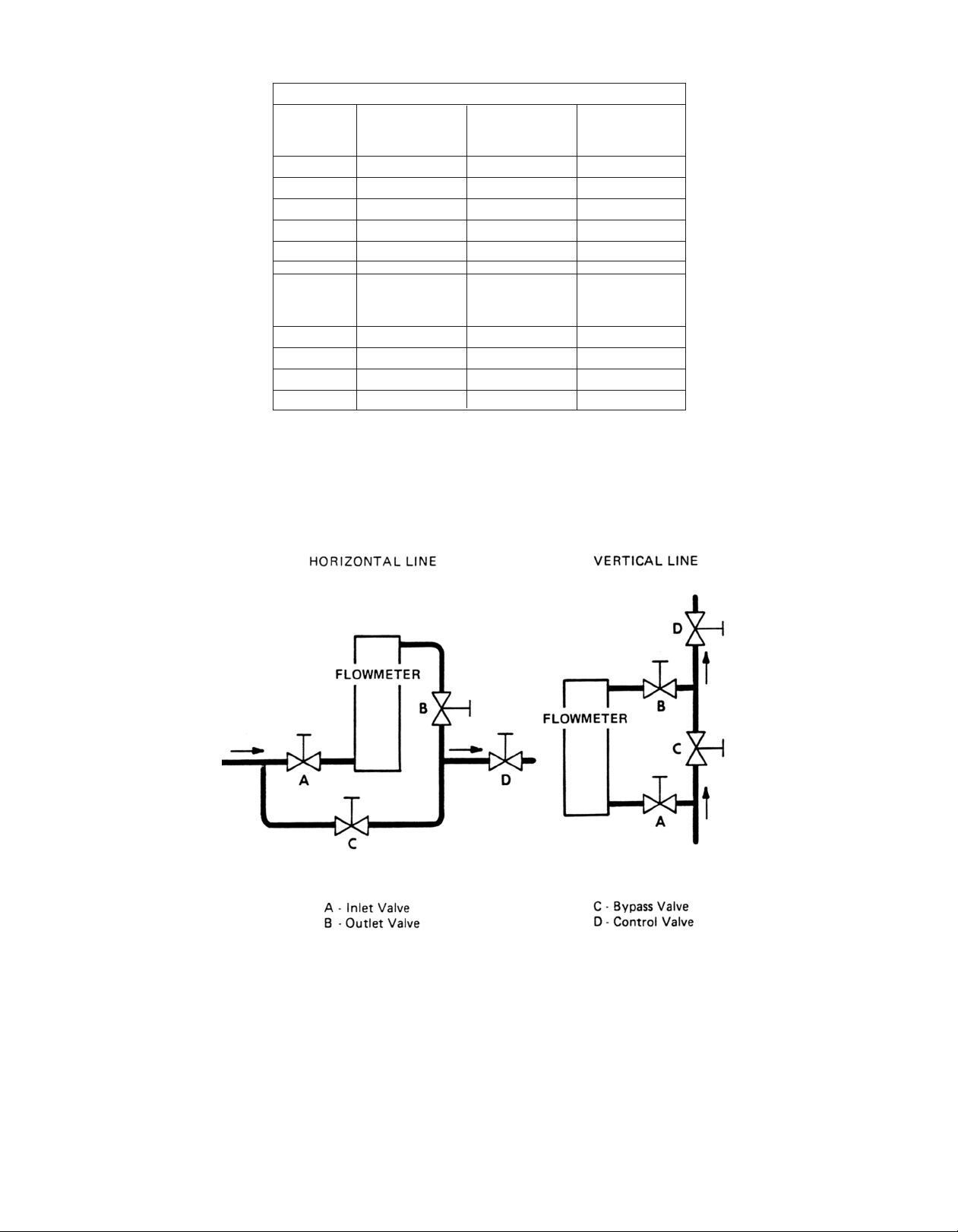
TYPICAL INSTALLATIONS
RECOMMENDED INSTALLATION PRACTICES
Water hammer and surges can be damaging to any flowmeter and must always be avoided.
Water hammer occurs when a liquid flow is suddenly stopped as with quick closing and solenoid operated valves. Surges
occur when flow is suddenly begun, as when a pump is turned on at full power or a valve is quickly opened.
Liquid surges are particularly damaging to flowmeters if the pipe is originally empty. To avoid damaging surges, fluid lines
should remain full (if possible) and pumps should be brought up to power slowly and valves opened slowly. In addition, to
avoid both water hammer and surges, a surge chamber should be installed.
3
 Loading...