

Page 1
Shop online at
User’s Guide
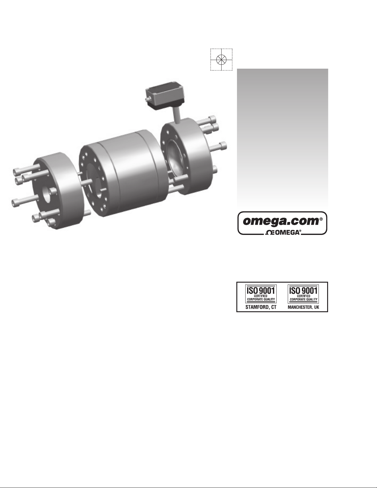
FHG FLOW METERS
Page 2

Servicing North America:
U.S.A.: Omega Engineering, Inc., One Omega Drive, P.O. Box 4047
ISO 9001 Certified Stamford, CT 06907-0047 USA
Canada: 976 Bergar
Laval (Quebec), Canada H7L 5A1
Toll-Free: 1-800-826-6342 TEL: (514) 856-6928
FAX: (514) 856-6886 e-mail: [email protected]
For immediate technical or application assistance:
U.S.A. and Canada: Sales Service: 1-800-826-6342/1-800-TC-OMEGA
®
Customer Service: 1-800-622-2378/1-800-622-BEST
®
Engineering Service: 1-800-872-9436/1-800-USA-WHEN
®
Mexico: En Español: 001 (203) 359-7803 FAX: (001) 203-359-7807
Servicing Europe:
Benelux: Managed by the United Kingdom Office
Czech Republic: Frystatska 184
733 01 Karviná, Czech Republic
Toll-Free: 0800-1-66342 TEL: +420-59-6311899
FAX: +420-59-6311114 e-mail: [email protected]
France: Managed by the United Kingdom Office
Toll-Free: 0800 466 342 TEL: +33 (0) 161 37 29 00
FAX: +33 (0) 130 57 54 27 e-mail: [email protected]
Germany/Austria: Daimlerstrasse 26
D-75392 Deckenpfronn, Germany
Toll-Free: 0 800 6397678 TEL: +49 (0) 7059 9398-0
FAX: +49 (0) 7056 9398-29 e-mail: [email protected]
United Kingdom: OMEGA Engineering Ltd.
ISO 9001 Certified One Omega Drive, River Bend Technology Centre, Northbank
Irlam, Manchester M44 5BD England
Toll-Free: 0800-488-488 TEL: +44 (0)161 777-6611
FAX: +44 (0)161 777-6622 e-mail: [email protected]
OMEGAnet®Online Service Internet e-mail
omega.com [email protected]
It is the policy of OMEGA Engineering, Inc. to comply with all worldwide safety and EMC/EMI
regulations that apply. OMEGA is constantly pursuing certification of its products to the European New
Approach Directives. OMEGA will add the CE mark to every appropriate device upon certification.
The information contained in this document is believed to be correct, but OMEGA accepts no liability for any
errors it contains, and reserves the right to alter specifications without notice.
WARNING: These products are not designed for use in, and should not be used for, human applications.
Page 3
OPERATING INSTRUCTIONS
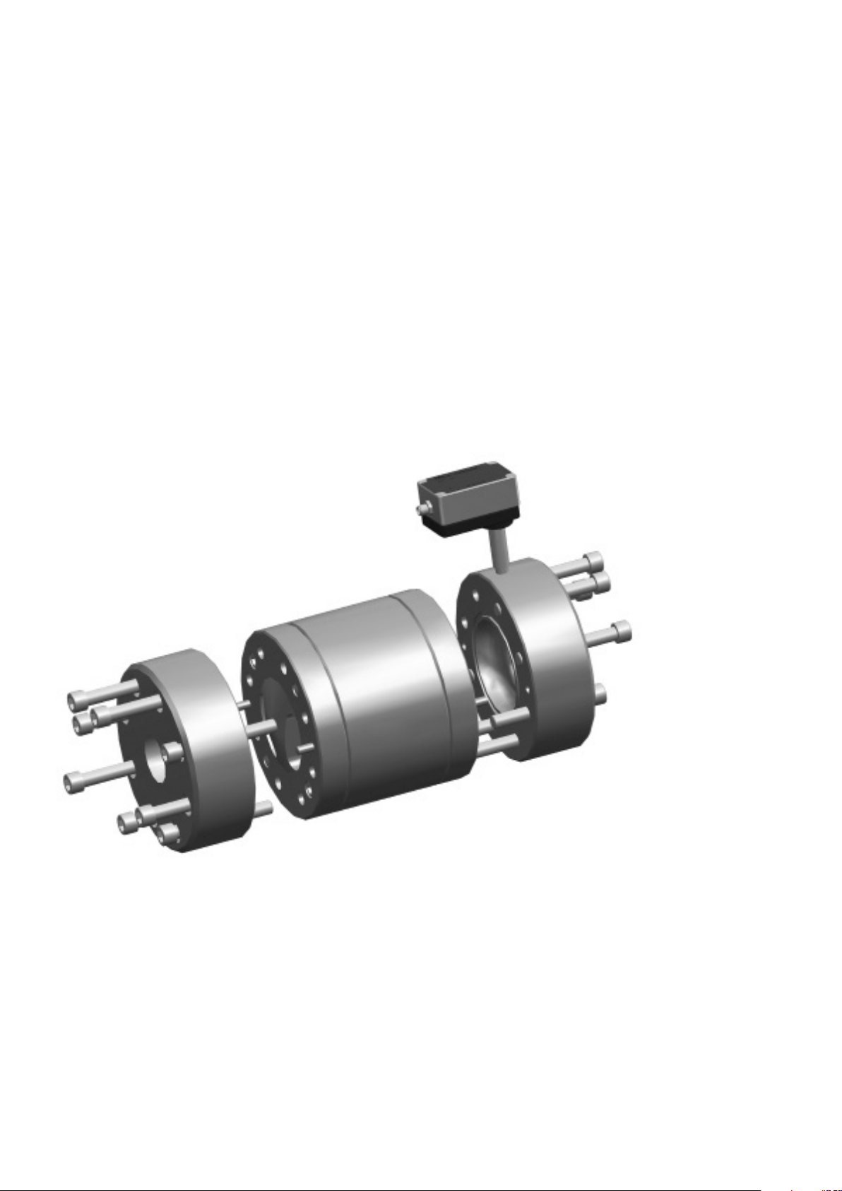
For FHG Series Flow Meters
Page 4

Table of Contents
Page
Important Basic Information. . . . . . . . . . . . . . . . . . . . . . . . . . . . . . . . . . . . . . . . . . . . . . . . . . . . . 3
1. Function Description of the FHG Flow Meters .................................... 3
2. General Description. . . . . . . . . . . . . . . . . . . . . . . . . . . . . . . . . . . . . . . . . . . . . . . . . . . . . . . . . 4
3. FHG Flow Meter Selection ................................................... 4
4. Declaration of Conformity .................................................... 4
5. General Operating Requirements. . . . . . . . . . . . . . . . . . . . . . . . . . . . . . . . . . . . . . . . . . . . . . 4
6. Maximum Operating Pressure. . . . . . . . . . . . . . . . . . . . . . . . . . . . . . . . . . . . . . . . . . . . . . . . . 5
7. Information about the EU Pressure Equipment Directive 97/23/EC ................... 5
8. Flow Rate Measuring Range . . . . . . . . . . . . . . . . . . . . . . . . . . . . . . . . . . . . . . . . . . . . . . . . . . 5
9. Mounting the Flow Meter. . . . . . . . . . . . . . . . . . . . . . . . . . . . . . . . . . . . . . . . . . . . . . . . . . . . . 6
10. Cleaning and Flushing of Pipeline before Initial Start-Up ..........................6
11. Fluid Filtering. . . . . . . . . . . . . . . . . . . . . . . . . . . . . . . . . . . . . . . . . . . . . . . . . . . . . . . . . . . . . . 7
12. Sensor Electronics Function . . . . . . . . . . . . . . . . . . . . . . . . . . . . . . . . . . . . . . . . . . . . . . . . . . 7
13. Pulse Filtering . . . . . . . . . . . . . . . . . . . . . . . . . . . . . . . . . . . . . . . . . . . . . . . . . . . . . . . . . . . . 10
14. Programming the Preamplier Electronics .....................................11
15. Signaling LEDs ...........................................................12
16. Operating Mode Messages ................................................12
17. Alarm and Warning Messages ..............................................13
18. Preamplier Technical Data. . . . . . . . . . . . . . . . . . . . . . . . . . . . . . . . . . . . . . . . . . . . . . . . . 13
19. Preamplier Pin Assignment. . . . . . . . . . . . . . . . . . . . . . . . . . . . . . . . . . . . . . . . . . . . . . . . . 13
20. Maintenance ............................................................14
21. Returning for Repairs and Sample Devices. . . . . . . . . . . . . . . . . . . . . . . . . . . . . . . . . . . . . 15
22. FHG Flow Meter Technical Data ............................................15
23. FHG Flow Meter Flow Characteristics ........................................16
24. FHG Flow Meter Dimensions ...............................................17
25. Pin Assignment ...........................................................18
26. Connection Diagram . . . . . . . . . . . . . . . . . . . . . . . . . . . . . . . . . . . . . . . . . . . . . . . . . . . . . . 19
The current publication of this operating instruction supersedes all information from previous
publications. Omega reserves the right to make changes and substitutions. Omega is not liable
for any printing errors. Reproduction, including excerpts, is permitted only after written appro val by Omega. Omega reserves the right to modify technical data at any time. Last revised:
12/2012
2
Page 5
Important basic information
These installation and operating instructions should provide you with the information you need to properly install and commission
the ow meter. Installation, commissioning and testing are to be performed by trained and qualied personnel only. These operating
instructions must be read and applied carefully to ensure proper, trouble-free and safe operation of the ow meter. Omega is not
liable for any damage incurred resulting from not complying with the instructions in this operating instruction. It is not permitted in
any case to open the device.
1. Function Description of the FHG Flow Meters
FHG ow meters measure the ow rate based on the screw pump principle.
A pair of rotors tted precisely into the housing constitutes the measuring
element. An integrated gear and non-contact signal pick-up system detects
the rotations of the measuring element and converts them to digital pulses.
Together with the housing walls, the rotor edges form closed measuring
chambers in which the uid is transported from the inlet to the outlet side.
The uid volume put through within one main rotor rotation is the rotation
volume, which is divided by the sensing gear and digitised, processed and
output in the sensor module.
Advantages
• High degree of precision that is mostly independent of viscosity
• Pulsation-free measurement
• Lowest pressure losses
•
Short response time due to innovative rotor prole and
• Highest functionality due to intelligent sensor technology
• Gentle uid measurements
Sensor System Explanation
The non-contact pick-up system consists of two GMR bridges (sin /cos), which
are located in a sensor unit in cartridge design. It detects the movement of
the sensing gear and routes the sin/cos signals to the preamplier electronics.
The preamplier electronics digitise and amplify the sensor signals and multiply them by a high-resolution interpolator using adjustable settings. The
square wave signals are bidirectional and can be utilised by any evaluating
instrument as well as computers and PLC controls.
The resolution is selectable in steps from factor 1 to 128.
In case of a 1-channel evaluation, a separate directional signal is available.
An adjustable pulse lter can offset and suppress negative ows (e.g. generated by vibrations) while still in the device.
The frequency of the output signals is proportional to the ow (volume ow)
and depends on the respective ow meter size. The frequency range is from
0 to 100 kHz. The preamplier is protected against reverse polarity and
incorrect connection. It is designed for media temperatures of -30°C to
+120°C and is mounted directly on the FHG ow meter.
3
Page 6

2. General Description
Please follow all instructions in this manual to ensure the trouble-free operation of the FHG ow meters. Omega does not assume responsibility or
liability for damages resulting from noncompliance with these instructions.
3. FHG Flow Meter Selection
The device may only be opened within the warranty period after consultation and approval by Omega.
For the trouble-free, safe, and reliable operation of the ow meters, selecting the correct type and size is critical. Because of the wide variety of
applications and ow meter designs, the technical data in the Omega catalog are general in nature. Certain properties of the devices are dependent
4. Declaration of Conformity
Flow meters of the ”FHG“ series have been tested for their electromagnetic
compatibility and interference emissions as outlined by the EMC Directive
and are in compliance with the applicable statutory EMC Directives.
They cannot be operated independently, are connected by cable to a power source, and provide digital electrical signals for electronic evaluation.
All ow meters have a declaration of conformity, which can be requested
if necessary.
5. General Operating Requirements
Before assembly, commissioning or operation, check and verify the following
properties & aspects of the respective circumstances of your system to ensure
operation is trouble-free, safe, and reliable.
on type, size and measuring range, as well as the liquid to be measured.
Please contact Omega or one of our sales and service representatives for
detailed information about the appropriate ow meter for your particular
application.
Since the electromagnetic compatibility of the entire measuring system is also dependent on the installation of the cables, the correct
connection of the shield, and each individual connected device, all
components must comply with the EMC Directive, and the electromagnetic compatibility of the entire system, machine, or system must be
ensured as well.
All ow meters have been tested in accordance with the applicable statutory EMC Directives of EN 61000-6 and are CE certied. The EC conformity
marking is the CE mark afxed to all ow meters.
1. The Fluid to be Processed
Are the flow meter seals and materials compatible with for the fluid and any cleaning agents that will be used?
Is the uid viscous or abrasive? Have you properly sized the meter and selected appropriate bearing materials?
Is the uid dirty or does it contain contaminants/pollutants and solid particles that may require ltration?
Does the uid have llers or other additives? What grain sizes do these solids have, and could they block the measuring element?
Is it necessary to install an upstream hydraulic lter (see ltering requirements in section 22 of this document)?
Are tubes and pipes clean and free of assembly residues such as chips, weld spatter?
Is the tank clean and is it impossible for impurities or foreign substances to reach the pipeline or tubing system from the tank?
Is a different uid used frequently and is the system sufciently ushed and rinsed in between?
Are pipelines/tubes and the entire system completely deaerated (the system should be slowly lled with uid before operation at full ow
to avoid hydraulic shock on the mechanical components)?
2. Hydraulic Properties of the System
Is the max. operating pressure of the system less than the max. permissible operating pressure of the ow meter?
Is the max. pressure drop ∆p (at ow meter) below the max. permissible pressure drop?
Is the pressure drop ∆p not excessive with max. ow (e.g. high viscosity)?
Does the ow range of the ow meter (dependent on the viscosity) correspond with the present ow?
Please note that the ow range is less with higher viscosity!
Does the temperature range of the ow meter correspond with the present max. temperature of the uid?
Is the cross-section of the pipelines/tubes large enough and are there no overly large pressure drops in the system?
Is the hydraulic connection (inlet/outlet) connected corrected and sealed properly?
Note: A blocked ow meter can stop t he entire ow. Does the sy stem feature an overpr essure / by pass valve? T his valve must be chec ked and
maintained at regular intervals.
4
Page 7
3. Electronic Evaluation and Electrical Safety
Does the supply voltage of the ow meter match the available power supply?
Is the supply voltage to the power supply adapter or the evaluating device sufciently ltered?
Does the output of the supply voltage correspond with the required output?
Is the electrical connection established based on the enclosed wiring plan (see page 19)?
Is the cable shield correctly grounded on both sides to a clean common ground (PE)?
Is there a potential difference between the ground on the ow meter and at the evaluating device?
Is the ow meter permanently grounded (PE) (e.g. via the pipelines)?
If the measuring element of the flow meter is insulated from ground (PE), the meter must be grounded with a cable!!
Is the 4-pin to 5-pin round pin plug of the connection cable rmly attached to the plug of the ow meter?
Are the wires at the evaluating device connected correctly?
Does the entire system meet the legal rules and regulations concerning electromagnetic compatibility (EMC)?
Is compliance with all local rule and regulations, applicable rules, guidelines and basic conditions of the EMC ensured?
Syste ms where a malf unction or fa ilure may lead to p ersonal inju ries must be equ ipped with suitable safety mechanisms. The funct ion of these
safety mechanisms must be checked at regular intervals.
6. Maximum Operating Pressure
Before installing the ow meter, you must check whether the max. operating
pressure of the system does not exceed the max. permissible operating
pressure of 450 bar of the ow meter. Make sure to keep in mind that peak
pressures may occur when operating the system.
Important:
Please contact Omega with all operating pressures > 450 bar and in case of special models.
7. Information about the EU Pressure Equipment Directive 97/23/EC
Omega ow meters of the ”FHG“ series qualify as “pressure equipment“ as
dened by Section 1, Paragraph 2.1.4. of the directive listed above and as
such are affected by the regulations of this directive.
Omega ow meters must therefore meet the technical requirements specied in Section 3, Paragraph 1.4 of the directive. The uids to be measured
are for the most part Group 2 uids acc. to Section 9, Paragraph 2.2.
Omega ow meters do not reach the limit values specied by Section 3,
Paragraph 1.1. The technical requirements for Omega ow meters are
therefore conned to the criteria specied in Section 3, Paragraph 3. This
means that the devices must be designed and manufactured in accordance
with the provisions of good engineering practice applicable in a member
state. This is hereby conrmed. The section also stipulates that such pressure equipment and components or accessories are not allowed to bear
the CE marking in accordance with the Pressure Equipment Directive. This
means that a declaration of conformity is not issued for Omega ow meters
and the devices are not provided with the CE mark as pertaining to Directive 97/23/EC.
8. Flow Rate Measuring Range
The ow rate measuring range specied in the data sheet (Q
of the ow meter refers to the test uid ‚hydraulic oil‘ with a viscosity of
21 m m2/s at a temperature of 20°C. For this measuring range, Omega
species accuracy up to 0.3% of the measured value and a repeatability
of 0.05%.
min
– Q
)
In uids with low viscosity (< 21 mm²/s), the measurement accuracy de-
max
grades while it may improve with uid with a high viscosity (> 21 mm²/s).
Note also that the ow measuring range is limited at higher viscosity (see
data sheet of the ow meter). The characteristic pressure loss curves are
listed in Section 23.
Important:
Verify that the specied maximum permissible operating pressure of the ow meter
can never be exceeded in any operating mode of the system. Also pay attention to the
ow measuring range, which is dependent on the viscosity of the uid to be measured.
5
Page 8
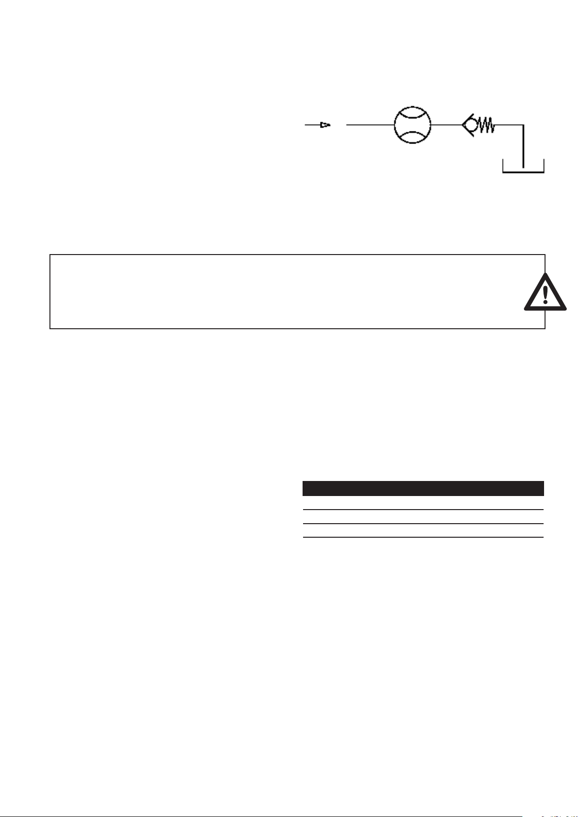
9. Mounting the Flow Meter
The ow meter should be mounted in an easily accessible location so that
disassembly to clean the measuring elements is easy. Since ow meters
operate in any installation position and ow direction, you can mount it
anywhere in your system. When installing the ow meter, make sure that
liquid remains in the ow meter even at standstill of the system and that the
ow meter can never run dry. The outlet of the ow meter should always
have a certain backpressure since this xes the measuring element of the
ow meter in the liquid column (the measuring element uses to support itself
on the liquid column) and the pipeline cannot empty itself. In critical cases,
or if the pipeline can run empty in standstill or standby mode, it is always
advisable to install an additional non-return check valve in the outlet line.
Fig. 1: Flow meter with backpressure
Flow meter
Important:
Make sure that the ow meter measuring elements are always completely lled both
in inow and outow and that the outow has a little backpressure. This prevents the
measuring elements from being damaged by a sudden and steep increase of ow and
at the same time improves measurement accuracy.
Non return valve
Tank
Flow meters of the ”FHG“ series can be installed in the pipeline. Always
select large cross-sections (if possible) for the hydraulic inlet and outlet or
the entire pipeline system. This reduces the pressure drop and the ow rate
throughout the system.
Installation Notes
Installation Position
Any, note arrow indicating preferred direction if necessary (calibration arrow).Mount the device in such a way that the preamplier is turned away
from any potential heat source.
Straight pipe sections are not required in inlet/outlet.
Connecting Units
If the connecting units (mounting anges) are to be installed on-site, compliance with the specied torque is required.
Pipe Thread
Please comply with the screw-in depths and sealing systems. PTFE tape or
liquid sealants such as adhesives are not permitted!
Fastening
The devices must be installed stress-free into the pipeline. This is accomplished with fastening screws located at the face sides in the connecting units.
For stress-free assembly, the compressive strength may be limited!
Table 1: Starting torque of the connection units
FHG Flow Meter Size Torque
FH G 1xx2 70 Nm
FH G 1xx4 120 Nm
FH G 1xx5 240 Nm
FH G 1xx7 160 Nm
10. Cleaning and Flushing of Pipeline before Initial Start-Up
Before initial start-up of the ow meter, you must ush and clean the whole
system to prevent contaminants from reaching the measuring elements during the assembly and installation. Foreign matter or contaminants may block
the ow meter or severely damage it so that the ow meter readings are no
longer valid and the device must be returned for repairs. After completion
of the installation or piping, you must rst ush the entire pipeline system
and carefully clean and ush the tank. This requires that the ow sensor is
removed from the uid circuit to ush out all foreign matter or contaminants
(e.g. chips, metal parts) without problems. Use a rinsing uid that is compatible with the subsequent used uid and will not cause adverse reactions.
Such information can be obtained from the supplier or manufacturer of the
uid or from Omega.
Flow meters are sensors manufactured with a high degree of precision.
They have mechanical measuring elements consisting of two rotors tted
into the housing with narrow gaps. Even the smallest damage to the rotors
causes a measuring error. Always make sure that foreign matter or contaminants cannot reach the measuring elements and that the uid owing
through the ow meter is always free of pollutants and particles. Once the
system is thoroughly ushed and no extraneous material is in the piping system, you can mount the ow meter into the uid circuit and start the actual
initial startup process.
6
Page 9
11. Fluid Filtering
Heavily contaminated uids or foreign matter in the uid can block, damage, and even destroy the ow meter. In these cases, always install a
sufciently large lter in front of the ow meter so that foreign particles and
Table 2: Upstream lters
Flow meter size Filter size for
ball bearing
FH G 1xx2 250 µm
FH G 1xx4 250 µm
FH G 1xx5 500 µm
FH G 1xx7 500 µm
solids are prevented from entering the measuring elements, thus preventing
damage to the ow meter. The required ltering depends on the size, bearing, and design of the ow meter.
The lter size for ow meters with slide bearings, in special designs, or with
specially adapted measuring element tolerances can be obtained from
Omega upon request.
Important:
A blocked ow meter is capable of stopping the entire ow.
An overpressure / bypass valve must be installed in the system side.
12. Sensor Electronics Function
The liquid to be measured ows through the rotor chambers in axial direction, resulting in an even rotation of the screw spindles.
This is done especially gentle and with very low resistance for the uid to
be measured as well as pulsation-free and almost free of leaks due to the
specially designed uidic prole geometry.
A magnet wheel permanently afxed to the rotors is scanned without
contact with a sensor module. The non-contact pick-up system consists of
two GMR bridges (sin /cos), which are located in a sensor unit in cartridge
design. It detects every movement of the sensing gear and routes the sin/
cos signals to the preamplier electronics. The preamplier electronics digitise and amplify the sensor signals and multiply them by a high-resolution
interpolator using adjustable settings. The square wave signals phase-shifted by 90° are bidirectional and can be utilised by any evaluating device
as well as computers and PLC controls.
The ow is proportional to the edges/pulse count and the ow rate is proportional to the frequency. The adjustable interpolator can be used to adjust the resolution explicitly to the downstream connected evaluating unit
for obtaining highly precise measuring results of the entire system. This applies to the following application cases, for example:
• Measuring, controlling, and regulating high viscosity uids
• Measuring, controlling, and regulating in lower ow ranges
• Measuring, controlling, and regulating when passing through zero
• Measuring, controlling, and regulating in both ow directions
• Measuring, controlling, metering, and lling of small volumes
The resolution is selectable in steps from factor 1 to 128. The frequency
range is from 0 to 100 kHz.
In case of a 1-channel evaluation, a separate directional signal is available.
The preamplier is protected against reverse polarity and incorrect connection. It is designed for uid temperatures of -30°C up to +120°C and is
mounted directly on the FHG ow meter.
The uid volume passed through by one gear division of the sensing
wheel within the measuring element is divided by the set interpolation factor.
This forms the measurement volume per pulse (Vm) with the dened unit
[c m ³/pulse].
The frequency of the output signals can be calculated as follows:
Formula 1: Calculation of the output frequency with Q in l/min
Q x 1000
f=
Vm 60
Table 2, Formula 2, and the subsequent diagrams can be used to determine
the corresponding resolution or the corresponding IPF for the respective
application.
Adjustable interpolation factors IPF: 1, 2, 5, 10, 25, 32, 50, 64, 100, 128
7
Page 10

Table 3: Measurement volumes and K-factors
FHG 100
Interpolation
factor (IPF)
Switch
position
S3
Measurement
volume V
m
[cm3/Imp]
K-Factor
[Imp/l]
K-Factor
[Imp/
gal.]
1 0 0, 5815 172 0 6510
2 1 0,29075 3439 130 20
5 2 0,11630 8598 32549
10 3 0, 05815 17197 65098
25 4 0,02326 42992 162 74 5
32 5 0,01817 55036 208335
50 6 0, 01163 85985 325489
64 7 0,00909 110 0 11 416 4 4 0
100 8 0,00582 171821 650419
128 9 0,00454 220264 833797
FHG 800
Interpolation
factor (IPF)
Switch
position
S3
Measurement
volume V
m
[cm3/Imp]
K-Factor
[Imp/l]
K-Factor
[Imp/
gal.]
1 0 10,00000 100 379
2 1 5,00000 200 757
5 2 2,00000 500 1893
10 3 1,00000 1000 3785
25 4 0,40000 2500 9464
32 5 0,31200 3200 1 2113
50 6 0,20000 5000 18927
64 7 0,15625 6400 24227
100 8 0,10000 10000 37854
128 9 0,07813 12 799 484 51
FHG 400
Interpolation
factor (IPF)
Switch
position
S3
Measurement
volume V
m
[cm3/Imp]
K-Factor
[Imp/l]
K-Factor
[Imp/
gal.]
1 0 3,138 319 120 6
2 1 1,569 637 2413
5 2 0,6276 1593 6032
10 3 0 , 3138 3187 120 63
25 4 0,12552 7967 30158
32 5 0,09806 10198 38603
50 6 0,06276 15934 60 316
64 7 0,04903 20396 77207
100 8 0,03138 318 67 120632
128 9 0,02452 40783 15 438 2
FHG 2500
Interpolation
factor (IPF)
Switch
position
S3
Measurement
volume V
m
[cm3/Imp]
K-Factor
[Imp/l]
K-Factor
[Imp/
gal.]
1 0 37,00000 27 102
2 1 18,50000 54 204
5 2 7,40000 135 511
10 3 3,70000 270 1022
25 4 1,48000 675 2555
32 5 1,15 62 5 864 3270
50 6 0,74000 1350 511 0
64 7 0, 57813 1728 6540
100 8 0,37000 2700 10220
128 9 0,28906 3456 13081
Formula 2: Calculating the max. IPF
f
IPF ≈
max
Q
x Vm
x 1000
max
IPF1
x 60
The set IPF may not be larger than the calculated IPF!
IPF Interpolation factor
f
Max. processable input frequency
max
V
Measurement volume with IPF = 1 (volume of a gear structure of the sensing wheel)
mIPF1
Q
Max. operating ow in l/min
max
8
Page 11
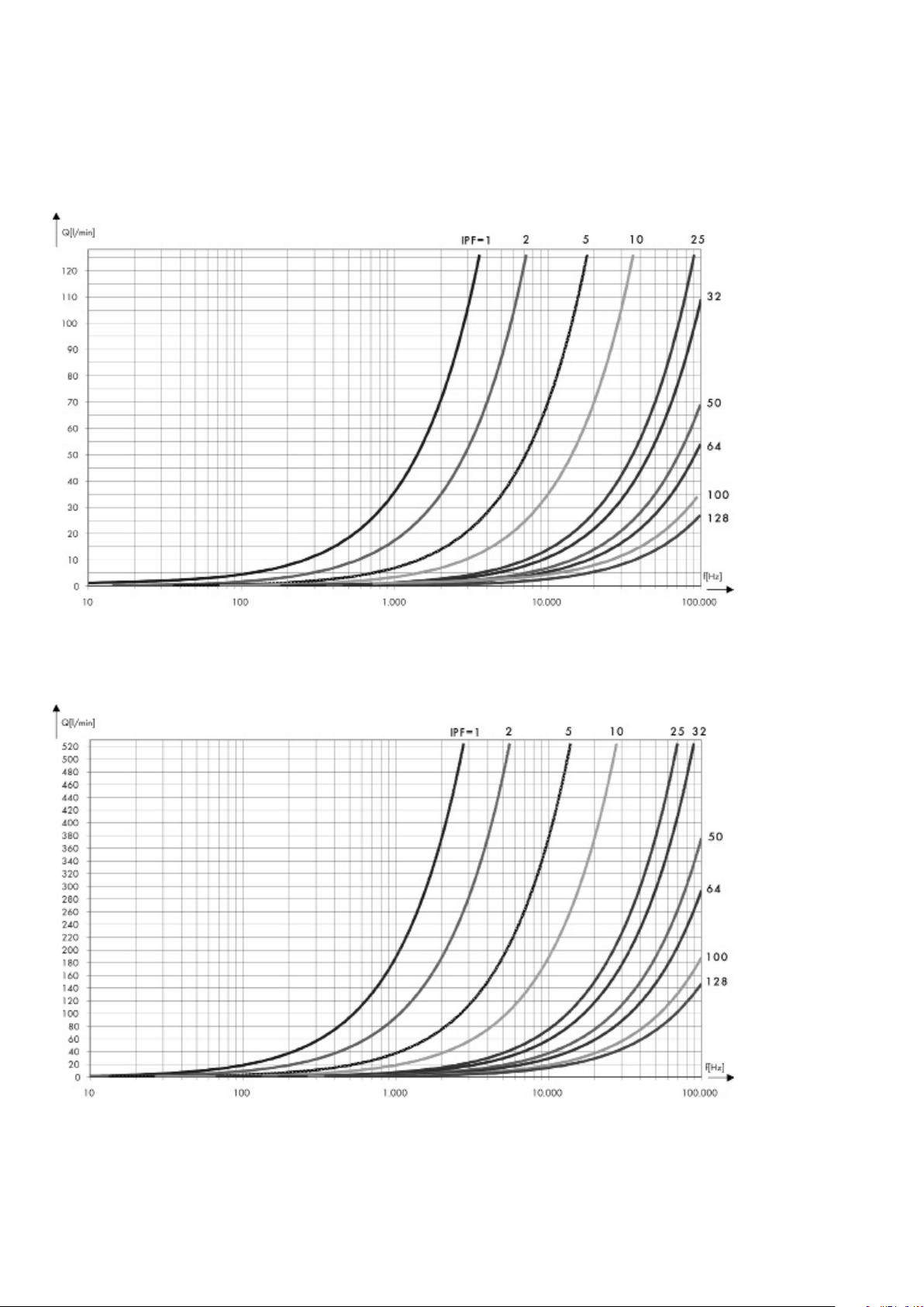
Flow diagrams vs frequency
FH G 1xx2
FLOW vs FREQUENCY
FHG 1xx4
FLOW vs FREQUENCY
9
Page 12
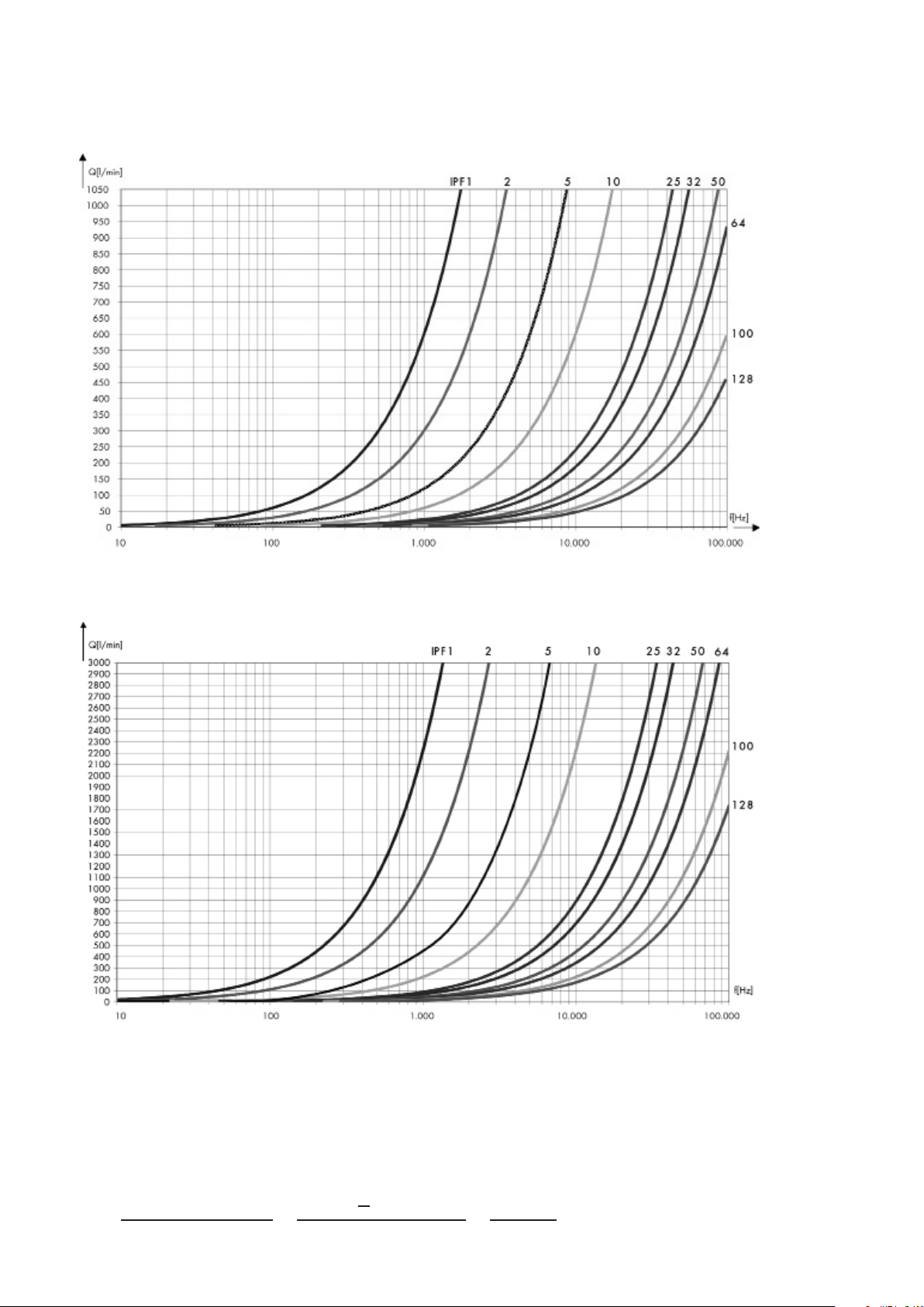
FH G 1xx5
FLOW vs FREQUENCY
FH G 1xx7
FLOW vs FREQUENCY
Example
Flow meter: FHG 1xx4
Max processable input frequency of the downstream evaluating unit: 20 kHz
Max. operating ow: 140 l/min
Path 1: The diagram yields an IPf of 25
Path 2:
f
IPF
max
≈
Q
10
x Vm
x 1000
max
IPF1
x 60
20.000 x 3,138 ml x 60 s
=
140 1000 ml
1
s
26,9 ≈ 25
=
Page 13
13. Pulse Filtering
Oscillations in uid systems manifest themselves through constant forward
and backward movements of the liquid column, which is also detected by the
rotor sensors and converted into proportional electronic pulses or edge sequences. Depending on the application, oscillations or vibrations can occur
during the ow rest phases or discontinuous ows. The pulses generated during the osciallation phase can be incorrectly interpreted by the downstream
evaluating unit or controller, which can be very distracting for the respective
operating process.
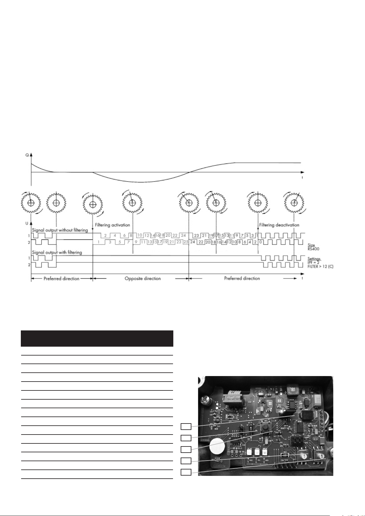
The signal ltering function of the internal electronics continuously offsets
these generated edges during the rapid forward and backward movements
of the rotor measuring unit. The signals at the channel outputs are also sup pressed at the same time until the internal offset is equalized or the initial
position of the rotor measuring unit has been reached again (see Fig. 3).
The user is able to set the degree of ltering in the form of partial volumes
using rotary coding switches.
Adjustable pulse ltering: 0Z, 0.25Z, 0.5Z, 0.75Z, 1.0Z, 1.25Z, 1.5Z, 1.75Z,
2.0Z, 2.25Z, 2.5Z, 2.75, 3.0Z, 3.25Z, 3.5Z, 3.75Z (Z: gear unit)
Fig. 3: Pulse ltering principle
Table 4: Suppressed volume with pulse ltering activation
[ml]
Filter
position
0 0 0 0 0
1 0.14 5375 0.7845 2.5 9.25
2 0.29075 1.569 5.0 18.50
3 0.436120 2.3535 7. 5 27. 7 5
4 0. 5 815 3.138 10.0 37.0 0
5 0.726875 3.9225 12 . 5 46.25
6 0.87225 4 .707 15.0 55.5
7 1.017625 5.4915 17. 5 64 .75
8 1.163 6. 276 20.0 74 . 0 0
9 1.308375 7.0605 22.5 83.25
10 (A) 1.45375 7.8 4 5 25.0 92.50
11 ( B ) 1.599120 8.6295 2 7. 5 101.75
12 (C) 1. 74 45 9. 414 30.0 111. 0 0
13 ( D) 1.889875 10.1985 32.5 120 .25
14 (E) 2.03525 10.983 35.0 12 9. 50
15 ( F) 2.180625 11. 7675 3 7. 5 138 . 75
FHG 1xx2 FHG 1xx4 FHG 1xx5 F HG 1x x 7
148
14. Programming the Preamplier Electronics
The electronics elements are quickly and easily set. There are two rotary
coding switches on the electronics (S3, S4), a jumper (B2), a switch (S2)
and a key (S2). With the rotary coding switches, the IPF and the degree of
ltering are programmed.
B2
S1
S2
S4
S3
Fig. 4: Preamplier electronics
11
Page 14
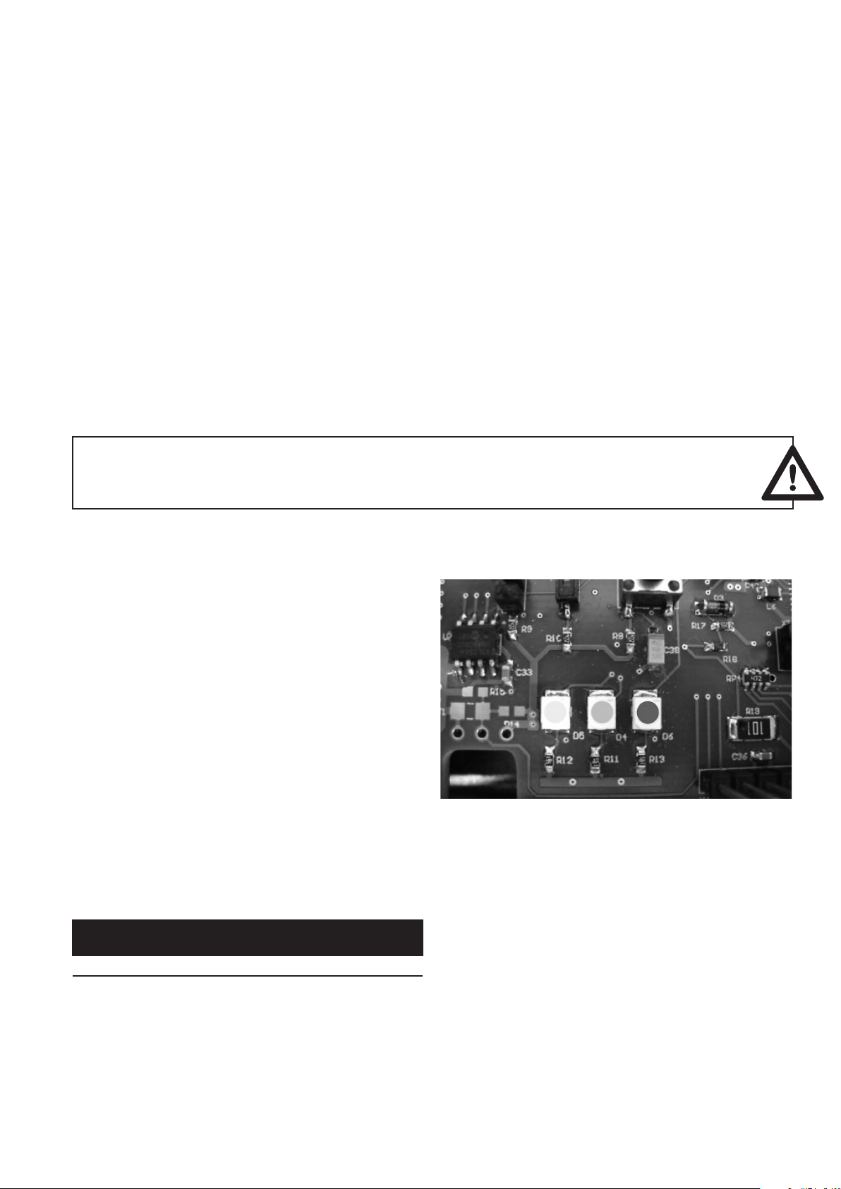
During initial startup, the switch S2 must rst be set to the corresponding
preferred direction of the ow. The positive ow direction of the FHG ow
meter system is specied in the top view of the 5-pin M12 connector. In this
case, the switch S1 must be set to ON. For the opposite negative direction,
the switch position is to be down and thus set to OFF. This setting ensures
that the pulse ltering is activated in the right direction from the very beginning after switching on the supply voltage.
Pin 5 of the M12 connector is either used for the separate direction signal
or an error signal. This is set accordingly with the bridge B2. The gure
above depicts the bridge attached to the middle and right pin of the 3-pin
row of pins, which routes the separate zero signal to the third output. If the
bridge is on the left and middle pin, the error signal in case of a fault is
output. A description of the error states is found in the ”Alarm and Warning
Messages“ chapter.
Ten different interpolation factors can be set with the coding switch S3. The
corresponding interpolation factors for the respective switch positions are
listed in Table 3. This setting can be changed at any time while the system
is running. Simply use a small screwdriver to adjust the rotary coding switch
and then briey press the S2 key for the acknowledgment. The new pulse
rate is enabled a once.
The rotary coding switch for the pulse ltering has 16 switch settings. The
degree of ltering is determined with quarter gear division increments. The
corresponding suppressed partial volumes of the respective size are listed
in Table 4. Changes can also be performed during operation and become
active after pressing the S2 key.
The electronics is sensitive to electrostatic discharges. People making
adjustments to the electronics must rst discharge their electrostatic charges
using a grounded object.
Important:
People making adjustments to the electronics must rst discharge their electrostatic
charges using a grounded object.
15. Signaling LEDs
The signa ling LEDs provide in formation ab out the corresp onding status o f the
electronics. These include certain operating and fault states (see Figure 5).
The three LEDs have a different combination of states for each signal. The
LEDs signal either operating modes or alarms and warnings. Operating
mode messages signal the respective mode that has been set.
Alarm and warning signals provide explicit information about overload,
conditions that can negatively affect the measurement, or component errors of the measuring system.
Fig. 5: Signaling LEDs of the preamplier electronics
16. Operating Mode Messages
Table 5: Operating mode messages
Mode Yellow
LED
Normal operation off on off off
Offset mode off Flashes off off
Green
LED
Red
LED
Error output
GreenYellow Red
12
Page 15

17. Alarm and Warning Messages
The electronics of the FHG ow meters can detect ve events that could
lead to measurement errors. In case of serious errors, the third output has
a ”high“ signal or a ”pulse“ signal if activated with the bridge B1. The
different error causes can be determined with the states of the three LEDs.
Table 6: Alarm and warning messages
Warning Yellow
Offset adjustment
necessary 1
Alarm Yellow
Interpolator electronics
errors 2
Error at pick-up 3 off o n / off on on
Flow overload on off on on
max. frequency range
exceeded
(>100 kHz) 4
Fluid temperature
> 120°C 5
Flashes on off off
Flashes off Flashes Pulse
Flashes on Flashes Pulse
Green
LED
LED
on on Flashes Pulse
LED
Gr een
LED
Red
LED
Red
LED
Error output
Error output
The red LED is linked with the error output. Each active state of this LED or
the error output signals an event that has negative effects on the measurements.
Description of the Error Messages
1. Offset adjustment necessary: The sensor and/or the preamplier elec tronics were replaced. A different size was set.
2. Electronics errors: Defective component in interpolator circuit, unable to
determine internal conguration values
3. Pick-up errors: The sensor is defective or quit working. The distance bet ween the sensor and the magnet wheel has changed = mechanical
damage
4. Overload: The maximum permissible ow range was exceeded
5. Frequency errors: The max. output frequency of 100,000 Hz was excee ded. The IPF is dimensioned too high for the respective ow
6. Temperature errors: The temperature of the uid is too high (> 120°C)
and may result in awed or incorrect measurements
18. Preamplier Technical Data
Scanning sensor 2 x GMR sensors in a bridge circuit (sin/cos)
Adjustment automatic offset adjustment
Resolution programmable 1, 2, 5, 10, 25, 32, 50, 64, 100, 128
Adjustable pulse ltering 0Z, 0.25Z, 0.5Z, 0.75Z, 1.0Z, 1.25Z, 1.5Z, 1.75Z, 2.0Z, 2.25Z, 2.5Z, 2.75, 3.0Z, 3.25Z, 3.5Z, 3.75Z (Z: gear unit)
Frequency up to 100 kHz
Output signals Channel A, channel B, directional signal DIREC (high: positive, low: negative) or error signal ERROR
(high or pulse: error)
Channel A and B two signal outputs for outputting the digital ow sensor signals, a channel offset of 90° between channel A and
channel B;
Flow direction Detection of ow direction from the channel offset of the signals from channel A to channel B or via the separate direc-
tional signal.
Outputs Three current-limited and short-circuit-proof power ampliers (channel A, channel B, DIREC / ERROR); integrated
adjustment to a characteristic impedance of 75 Ω; driver current approx. 300 mA at supply of 24 V; small saturation
voltage of up to 30 mA load current, short switching times, integrated freewheeling diodes against Vb and GND, ther mal shutdown with hysteresis; in case of error, the outputs are high impedance;
The 24 V line drivers are designed for control applications with cable adjustment
Error messages Electronics fault (e.g. faulty interpolator), sensor errors (e.g. sensor failure), offset adjustment necessary, overload (ow
peaks), frequency error (> 100 kHz), temperature error (> 120°C)
Operating voltage Vb = 10 … 28 VDC
Current consumption l
= approx. 40 mA, total current consumption depends on output load
noload
13
Page 16
19. Preamplier Technical Data
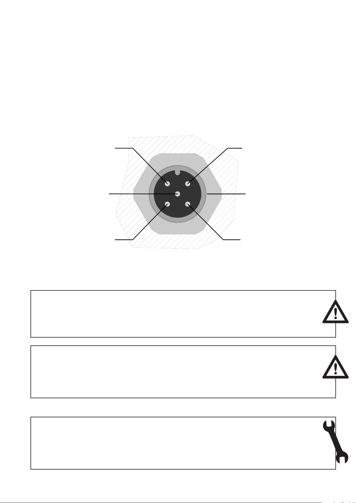
Fig. 6 depicts the pin assignment of the preamplier. This plug has ve pins.
Two pins are for the power supply (pin 1 and 3), two for the signal output
of channel 1, 2 (pins 2 and 4) and a separate output for error or direction
detection (pin 5).
However, please note that the cable shield at the plug side is on the metal
housing of the plug. The connection cable shield must be applied on both
sides. The shield is used to connect the PE from the evaluation electronics to
the preamplier housing and the measuring element of the ow meter. The
cable shield should always be continuous to the ow meter and not sepa-
rated by distribution boxes or junction boxes. Route the connection cable
as directly as possible from the evaluating device to the ow meter since
interruptions are always potential sources of error. The measuring elements
of the ow meter must be connected electrically with the protective earth
conductor (PE). This is generally ensured with the grounded pipelines.
If potential differences exist between the preamplier housing and
the protective conductor (PE) of the evaluating device, you must provide equalization.
Pin 2
Digital signal
Channel 1
Pin 5
Digital signal
ERROR/DIREC
Pin 3
Power supply
GND (-Vb = 0 V)
Plug top view
Figure 6: Flange plug of the preamplier housing
Pin 1
Power supply
Vb = 10-28 VDC
Metal housing connected with
shield and protective earthing
conductor PE
Pin 4
Digital signal
Channel 2
Important:
Use only well shielded connection cables with a wire cross-section of ≥ 4 to 5 x 0.25 mm². Please note
that the housing of the round pin plug is metallic, has a connection for the
shield and that the potential of the PE is connected to the cable shield and the housing
of the preamplier.
Important:
Please make sure that no additional inductors such as contactors, relays, valves, etc. are
connected to the power supply of the ow meter. These components are potential sources
of interference (especially if the inductors are not provided with adequate protective circuits), produce
high interference pulses during the switching, and may disrupt the function
of the ow meter even though it complies with the EMC directives.
20. Maintenance
Depending on the operating conditions, the service life and thus the specic characteristics
of the equipment are limited due to wear, corrosion, deposits, or aging. The operator is responsible for
carrying out periodic inspections, maintenance, and re-calibrations. Each observation of a malfunction
or damage makes it necessary to stop operation. We can loan a device for the duration of the overhaul
if requested. We recommend an annual inspection and recalibration.
14
Page 17

21. Returning for Repairs and Sample Devices
Repairs on the ow meter and other components can be carried out quickly
and efciently only if you include detailed information about the claim or
defect when returning the device. In addition, a safety sheet must be enclosed, clearly indicating what uid has been used with the ow meter and
how hazardous this uid is.
Compliance with the laws on occupational safety, such as Workplace Regulations (ArbStättV), Accident Prevention Regulations and Regulations on
Environmental Protection, Waste Law (AbfG) and Water Act (WHG), require that businesses protect their employees and other people as well as
the environment from harmful effects when handling hazardous substances.
22. FHG Flow Meter Technical Data
If additional precautions are required despite careful draining and cleaning of the ow meter, the associated required information must be included when returning the device. Please note that inspection and repair is
only performed on ow meters returned to Omega if the safety sheet of the
used uid is enclosed and if the ow meter has been completely cleaned
and ushed. This is to protect our employees and makes our work easier.
In case of noncompliance with this rule, the devices are returned to
the sender without attaching postage to the package.
Overall size Measuring range
(Q
) l/min.
max.
FH G 1xx2 0.50 – 100 (120) 15. 7 0. 5 815 1,720 220,000 450 250
FH G 1xx4 1.00 – 400 (525) 56.5 3.138 318 40,800 450 250
FH G 1xx5 4.00 – 800 (1,000) 180 .0 10 100 12,800 450 500
FH G 1xx7 10.00 – 2,500 (3,000) 666.0 37 27 3, 459 40 500
Frequency range 0 … 100 kHz, adjustable
Measuring accuracy ± 0.3% [0.5%]*, [1%]** of measured value at viscosit y of 21 cSt
*FHG 1xx5, **FHG 1xx7
Repeatability ± 0.05% with same operating conditions
Materials
Gray cast iron version EN -GJS – 400 – 15 (EN 1563) / 100 Cr 6
Stainless steel version Stainless steel 1.4305/1.4112, additional available upon request
Bearing Fluid- dependent as anti-friction bearing or SSIC/wolfram carbide friction bearing
Seals FPM (standard) PTFE, NBR, EPDM upon request
RV
ccm/rev.
VE
ccm/Imp.
K – Factor
Imp./l min.
K – Factor
Imp./l max.
P max.
bar
Filtering
µm
Fluid temperature -30°C ... +120°C
Viscosity range 1 … 1,000,000 cSt
Installation position Any using selectable connection units, also customer specic
Supply voltage 9 … 28 VDC
Current consumption 65 mA at 24 VDC unloaded
Delay time ≤ 8 mµs
Protection type IP 65
15
Page 18
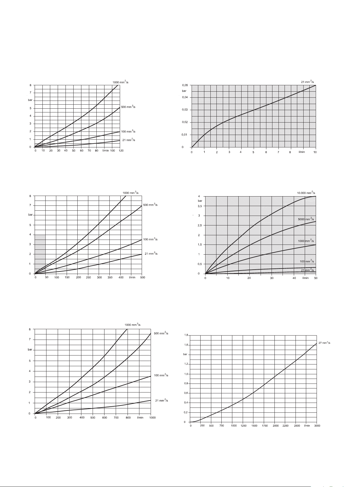
Baugröße 100
Baugröße 100
Size 1xx2
Flow range 0 up to 120 l/min
Durchussbereich 0 bis 120 l/min
Flow range 0 up to 10 l/min
Durchussbereich 0 bis 10 l/min
Durchusswiderstand ∆p
Flow range pressure drop ∆p
Baugröße 400
Size 1xx4
Flow range 0 up to 500 l/min
Durchussbereich 0 bis 500 l/min
Durchusswiderstand ∆p
Flow range pressure drop ∆pFlow range pressure drop ∆p
Durchusswiderstand ∆p
Flow range pressure drop ∆p
Durchuss Q Durchuss Q
Flow range Q
Durchussbereich 0 bis 50 l/min
Flow range 0 up to 50 l/min
Durchusswiderstand ∆p
Flow range Q
Flow range pressure drop ∆p
Durchuss Q
Durchuss Q
Flow range QFlow range Q
Baugröße 800
Size 1xx5
Durchussbereich 0 bis 1.000 l/min
Flow range 0 up to 1,000 l/min
Durchusswiderstand ∆p
Durchuss Q
Flow range Q
Size 1xx7
Flow range 0 up to 3,000 l/min
Flow range pressure drop ∆p
Flow range Q
Page 19
Vorverstärker
Sensormodul
Messanschluss
Erdung
Ringschraube
Anschlusseinheit
Anschlusseinheit mit Sensormodul
Anschlusseinheit Anschlusseinheit mit Sensormodul
Messanschluss
Anschluss
SAE 2
Vorverstärker Sensormodul Messanschluss G1/4 Erdung Ringschraube
Anschlusseinheit
AR. 2500-R..
Flanschanschlussmaße
DIN EN 1092
Gewicht 120 kg
FHG1xx5
Preamplier
Test Port
Connection unit
AR. 800- H..
Sensor module
Test Port
Ring bolt
Connection unit with sensor
module AR. 800 -H..
Earthing
Weight 81 kg
deep
FHG1xx7
Connection
Connection unit
AR. 800-X..
Preamplier
Connection unit with sensor
module AR. 800 -X ..
Sensor module
Test Port G 1/4
Earthing
Weight 81 kg
Ring bolt
Connection unit
AR. 2500-R..
18
Flange connection dimension
Weight 120 kg
Page 20
4 x M10-18 tief
Vorverstärker
Sensormodul
Messanschluss
Erdung
Anschlusseinheit
AR. 400-F..
Anschlusseinheit mit Sensormodul
AR. 400-F..
Anschlusseinheit
AR. 400-V..
Anschlusseinheit mit Sensormodul
AR. 400-V..
Gewicht 22 kg
Messanschluss
Anschluss
SAE 1 1/4
Gewicht 24,8 kg
M8-15 tief
beidseitig
4 x M14-25 tief
M8-15 tief
beidseitig
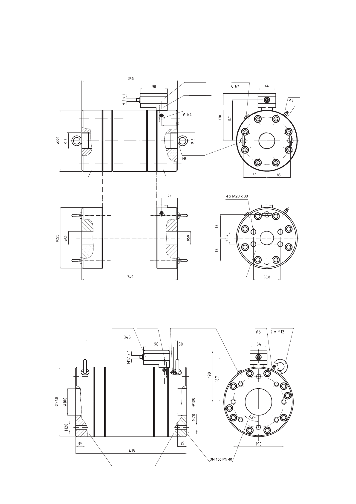
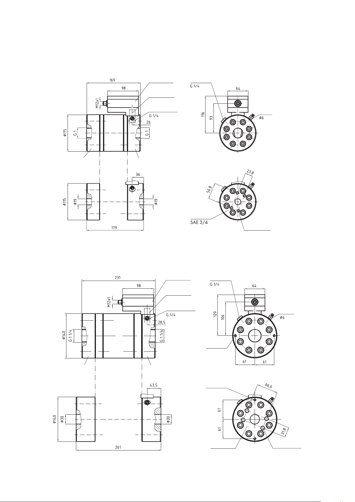
24. FHG Flow Meter Dimensions
FHG1xx2
Connection unit
AR. 100-E..
Connection unit
AR. 100-T..
Preamplier
Sensor module
Test Port
Connection unit with sensor
module AR. 100-E..
Connection unit with sensor
module AR. 100-T..
Test Port
Connection
Earthing
deep
Weight 12 kg
Weight 12.7 kg
FHG1xx4
Connection unit
AR. 400- F..
Connection unit with sensor
module AR. 400 -F..
Preamplier
Sensor module
Test Port
Test Port
M8-15 deep
on both sides
M8-15 deep
on both sides
Earthing
Weight 22 kg
Connection unit
AR. 400-V..
Connection unit with sensor
module AR. 400 -V..
Connection
deep
Weight 24.8 kg
17
Page 21
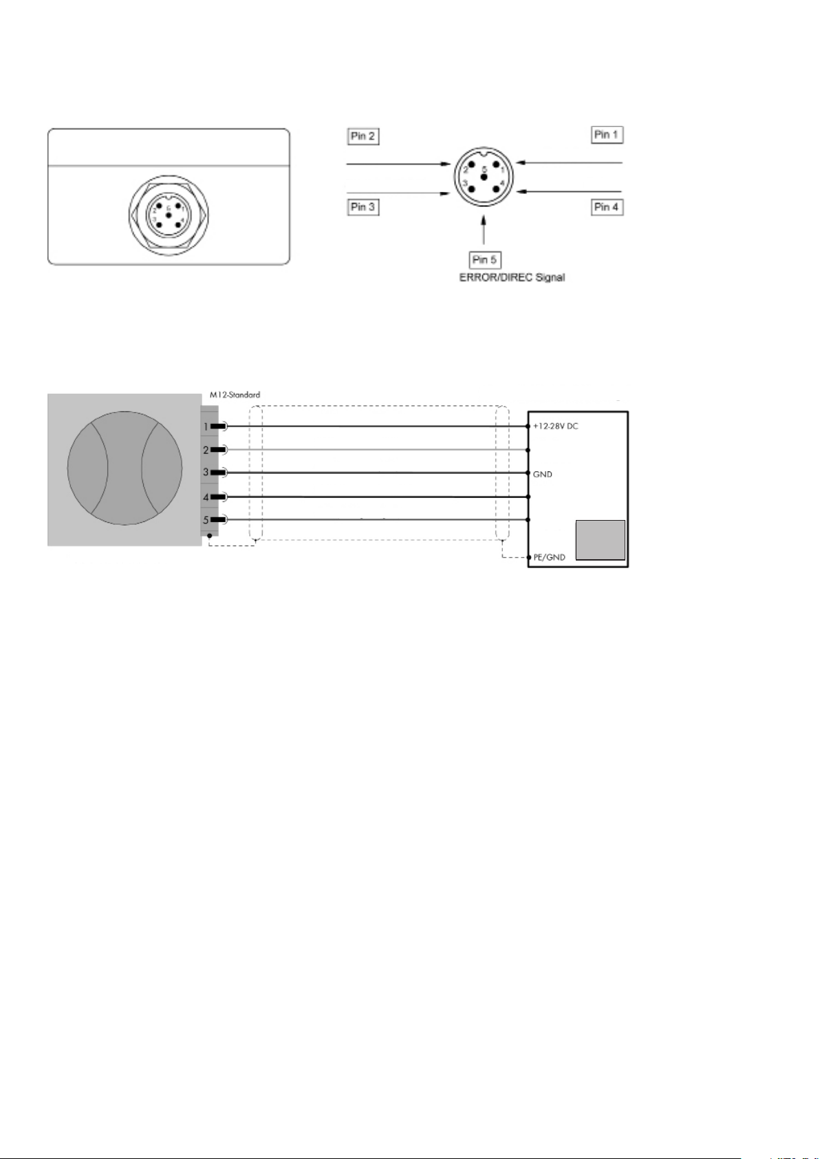
25. Pin Assignment
26. Connection Diagram
Flow sensor FHG
Channel 1
Power supply 0 voltage
channel 1 (white)
0 voltage (blue)
channel 2 (black)
Error/Direction (grey)
Power supply + voltage
Channel 2
Evaluating unit (e.g. display)
Signal
input 1
Signal
input 2
control
input
Q: 8 l/min
V: 11,53 l
direction: pos.
f: 424,9 Hz
19
Page 22

WARRANTY/DISCLAIMER
OMEGA ENGINEERING, INC. warrants this unit to be free of defects in materials and workmanship for a
period of 13 months from date of purchase. OMEGA’s WARRANTY adds an additional one (1) month
grace period to the normal one (1) year product warranty to cover handling and shipping time. This
ensures that OMEGA’s customers receive maximum coverage on each product.
If the unit malfunctions, it must be returned to the factory for evaluation. OMEGA’s Customer Service
Department will issue an Authorized Return (AR) number immediately upon phone or written request.
Upon examination by OMEGA, if the unit is found to be defective, it will be repaired or replaced at no
charge. OMEGA’s WARRANTY does not apply to defects resulting from any action of the purchaser,
including but not limited to mishandling, improper interfacing, operation outside of design limits,
improper repair, or unauthorized modification. This WARRANTY is VOID if the unit shows evidence of
having been tampered with or shows evidence of having been damaged as a result of excessive corrosion;
or current, heat, moisture or vibration; improper specification; misapplication; misuse or other operating
conditions outside of OMEGA’s control. Components in which wear is not warranted, include but are not
limited to contact points, fuses, and triacs.
OMEGA is pleased to offer suggestions on the use of its various products. However,
OMEGA neither assumes responsibility for any omissions or errors nor assumes liability for any
damages that result from the use of its products in accordance with information provided by
OMEGA, either verbal or written. OMEGA warrants only that the parts manufactured by the
company will be as specified and free of defects. OMEGA MAKES NO OTHER WARRANTIES OR
REPRESENTATIONS OF ANY KIND WHATSOEVER, EXPRESSED OR IMPLIED, EXCEPT THAT OF
TITLE, AND ALL IMPLIED WARRANTIES INCLUDING ANY WARRANTY OF MERCHANTABILITY
AND FITNESS FOR A PARTICULAR PURPOSE ARE HEREBY DISCLAIMED. LIMITATION OF
LIABILITY: The remedies of purchaser set forth herein are exclusive, and the total liability of
OMEGA with respect to this order, whether based on contract, warranty, negligence,
indemnification, strict liability or otherwise, shall not exceed the purchase price of the
component upon which liability is based. In no event shall OMEGA be liable for
consequential, incidental or special damages.
CONDITIONS: Equipment sold by OMEGA is not intended to be used, nor shall it be used: (1) as a “Basic
Component” under 10 CFR 21 (NRC), used in or with any nuclear installation or activity; or (2) in medical
applications or used on humans. Should any Product(s) be used in or with any nuclear installation or
activity, medical application, used on humans, or misused in any way, OMEGA assumes no responsibility
as set forth in our basic WARRANTY/DISCLAIMER language, and, additionally, purchaser will indemnify
OMEGA and hold OMEGA harmless from any liability or damage whatsoever arising out of the use of the
Product(s) in such a manner.
RETURN REQUESTS/INQUIRIES
Direct all warranty and repair requests/inquiries to the OMEGA Customer Service Department. BEFORE
RETURNING ANY PRODUCT(S) TO OMEGA, PURCHASER MUST OBTAIN AN AUTHORIZED RETURN
(AR) NUMBER FROM OMEGA’S CUSTOMER SERVICE DEPARTMENT (IN ORDER TO AVOID
PROCESSING DELAYS). The assigned AR number should then be marked on the outside of the return
package and on any correspondence.
The purchaser is responsible for shipping charges, freight, insurance and proper packaging to prevent
breakage in transit.
FOR WARRANTY
RETURNS, please have the
following information available BEFORE
contacting OMEGA:
1. Purchase Order number under which the product
was PURCHASED,
2. Model and serial number of the product under
warranty, and
3. Repair instructions and/or specific problems
relative to the product.
FOR NON-WARRANTY REPAIRS,
consult OMEGA
for current repair charges. Have the following
information available BEFORE contacting OMEGA:
1. Purchase Order number to cover the COST
of the repair,
2. Model and serial number of the product, and
3. Repair instructions and/or specific problems
relative to the product.
OMEGA’s policy is to make running changes, not model changes, whenever an improvement is possible. This affords
our customers the latest in technology and engineering.
OMEGA is a registered trademark of OMEGA ENGINEERING, INC.
© Copyright 2009 OMEGA ENGINEERING, INC. All rights reserved. This document may not be copied, photocopied,
reproduced, translated, or reduced to any electronic medium or machine-readable form, in whole or in part, without the
prior written consent of OMEGA ENGINEERING, INC.
Page 23

Where Do I Find Everything I Need for
Shop online at omega.com
SM
Process Measurement and Control?
OMEGA…Of Course!
TEMPERATURE
Thermocouple, RTD & Thermistor Probes, Connectors, Panels & Assemblies
Wire: Thermocouple, RTD & Thermistor
Calibrators & Ice Point References
Recorders, Controllers & Process Monitors
Infrared Pyrometers
PRESSURE, STRAIN AND FORCE
Transducers & Strain Gages
Load Cells & Pressure Gages
Displacement Transducers
Instrumentation & Accessories
FLOW/LEVEL
Rotameters, Gas Mass Flowmeters & Flow Computers
Air Velocity Indicators
Turbine/Paddlewheel Systems
Totalizers & Batch Controllers
pH/CONDUCTIVITY
pH Electrodes, Testers & Accessories
Benchtop/Laboratory Meters
Controllers, Calibrators, Simulators & Pumps
Industrial pH & Conductivity Equipment
DATA ACQUISITION
Data Acquisition & Engineering Software
Communications-Based Acquisition Systems
Plug-in Cards for Apple, IBM & Compatibles
Datalogging Systems
Recorders, Printers & Plotters
HEATERS
Heating Cable
Cartridge & Strip Heaters
Immersion & Band Heaters
Flexible Heaters
Laboratory Heaters
ENVIRONMENTAL
MONITORING AND CONTROL
Metering & Control Instrumentation
Refractometers
Pumps & Tubing
Air, Soil & Water Monitors
Industrial Water & Wastewater Treatment
pH, Conductivity & Dissolved Oxygen Instruments
M-5241/0613
 Loading...