

Page 1
STATUS SCIENTIFIC CONTROLS
Issue:
2
Date:
04.01.12
Firmware:
V1.1.1r
FGD4, FGD10B and PC192-NT
Keypad
Page 2

STATUS SCIENTIFIC CONTROLS
Calibration / Configuration Keypad
FGD4, FGD10B and PC192-NT Gas Detector
TD18/026
Issue: 2 Change Note:
1778
Page 2
1. PACKAGE CONTENTS ...................................................................... 3
1.1. CALIBRATION / CONFIGURATION KEYPAD ....................................... 4
1.2. MENU MODE SELECTION .............................................................. 6
1.2.1. E : 01 – Sensor Zero ............................................................................ 7
1.2.2. E : 02 – Sensor Span ........................................................................... 7
1.2.3. E : 03 – Sensor Fsd.............................................................................. 7
1.2.4. E : 04 – Output Zero (4mA) .................................................................. 7
1.2.5. E : 05 – Output Span (20mA) ............................................................... 7
1.2.6. E : 08 – Sensor Type............................................................................ 8
1.2.7. E : 09 – Engineer diagnostics .............................................................. 8
1.2.8. E : 17 – Sensor gain, Toxic sensors .................................................... 9
1.2.9. E : 19 – Positive Zero Suppression .................................................... 10
1.2.10. E : 20 – Negative Zero Suppression .................................................. 10
1.2.11. E : 25 – Positive Zero Temperature Compensation .......................... 11
1.2.12. E : 34 – Positive Span Temperature Compensation ......................... 11
1.2.13. E : 35 – Negative Span Temperature Compensation ........................ 11
1.2.14. E : 36 – Positive Zero Temperature Compensation .......................... 11
1.2.15. E : 52 – Enable / Disable calibration buttons ..................................... 11
1.2.16. E : 77 – Firmware Version .................................................................. 11
2. CALIBRATION .................................................................................. 12
2.1. SENSOR CALIBRATION ............................................................... 12
2.1.1. Sensor Zero ........................................................................................ 12
2.1.2. Sensor Span ....................................................................................... 13
2.2. ANALOGUE OUTPUT CALIBRATION .............................................. 14
2.2.1. Analogue Output Zero ........................................................................ 15
2.2.2. Analogue Output Span ....................................................................... 15
3. LOW BATTERY……………………………………………………………16
3.1. LOW BATTERY INDICATION ....................................................... 126
Page 3
STATUS SCIENTIFIC CONTROLS
Calibration / Configuration Keypad
FGD4, FGD10B and PC192-NT Gas Detector
TD18/026
Issue: 2 Change Note:
1778
Page 3
1. PACKAGE CONTENTS
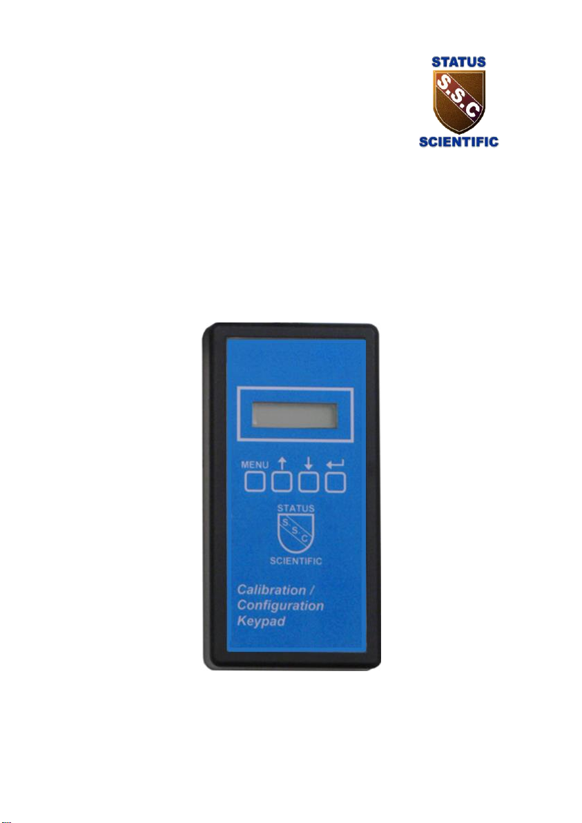
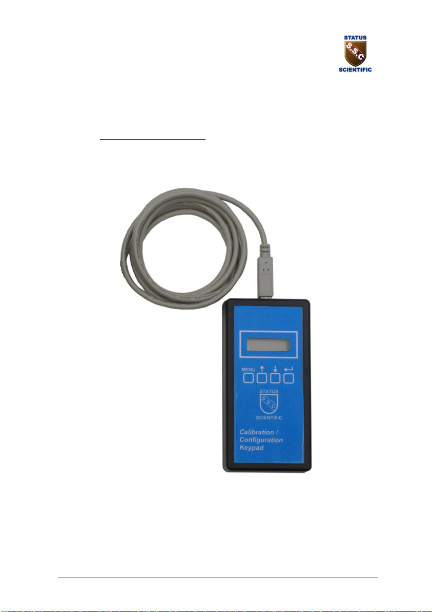
Calibration / Configuration Keypad
SS748
* Refer to www.status-scientific.com for Stock No’s for various gas types.
** The manual may be supplied on a CD
Page 4
STATUS SCIENTIFIC CONTROLS
Calibration / Configuration Keypad
FGD4, FGD10B and PC192-NT Gas Detector
TD18/026
Issue: 2 Change Note:
1778
Page 4
1 Scope of the manual
This manual relates to the keypad operation when used with the FGD4,
FGD10B and PC192-NT gas detectors.
1.1. Calibration / Configuration Keypad
The FGD10B sensor can be calibrated via a purpose designed keypad. The
keypad allows the user to carry out the following:
1) calibrate the sensor.
2) calibrate the 4 to 20 mA loop.
3) View the current gas level.
4) View the sensor raw data for diagnostic purposes.
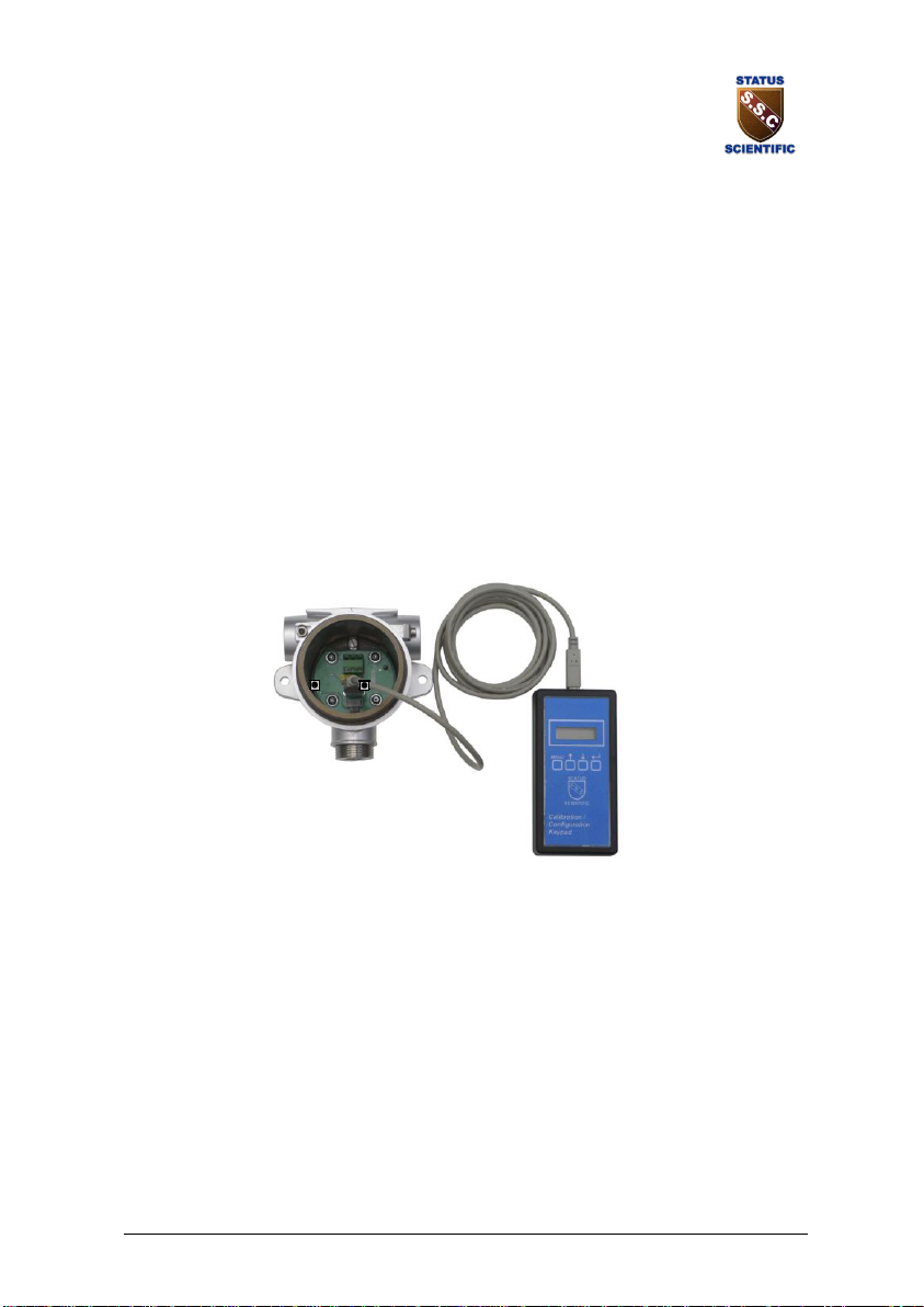
Connect the keypad into the FGD10B as shown below:
The display will give the following messages:
SSCL Company
- - - PELL Sensor type (02tc, PELL, Ir)
88:88 Segment test
SSCL Manufacturer
1.1.1r Firmware version
- - - -
0.0 Gas reading
Note: if the display is continually showing - - - - then the instrument is not
communicating with the keypad.
Page 5
STATUS SCIENTIFIC CONTROLS
Calibration / Configuration Keypad
FGD4, FGD10B and PC192-NT Gas Detector
TD18/026
Issue: 2 Change Note:
1778
Page 5
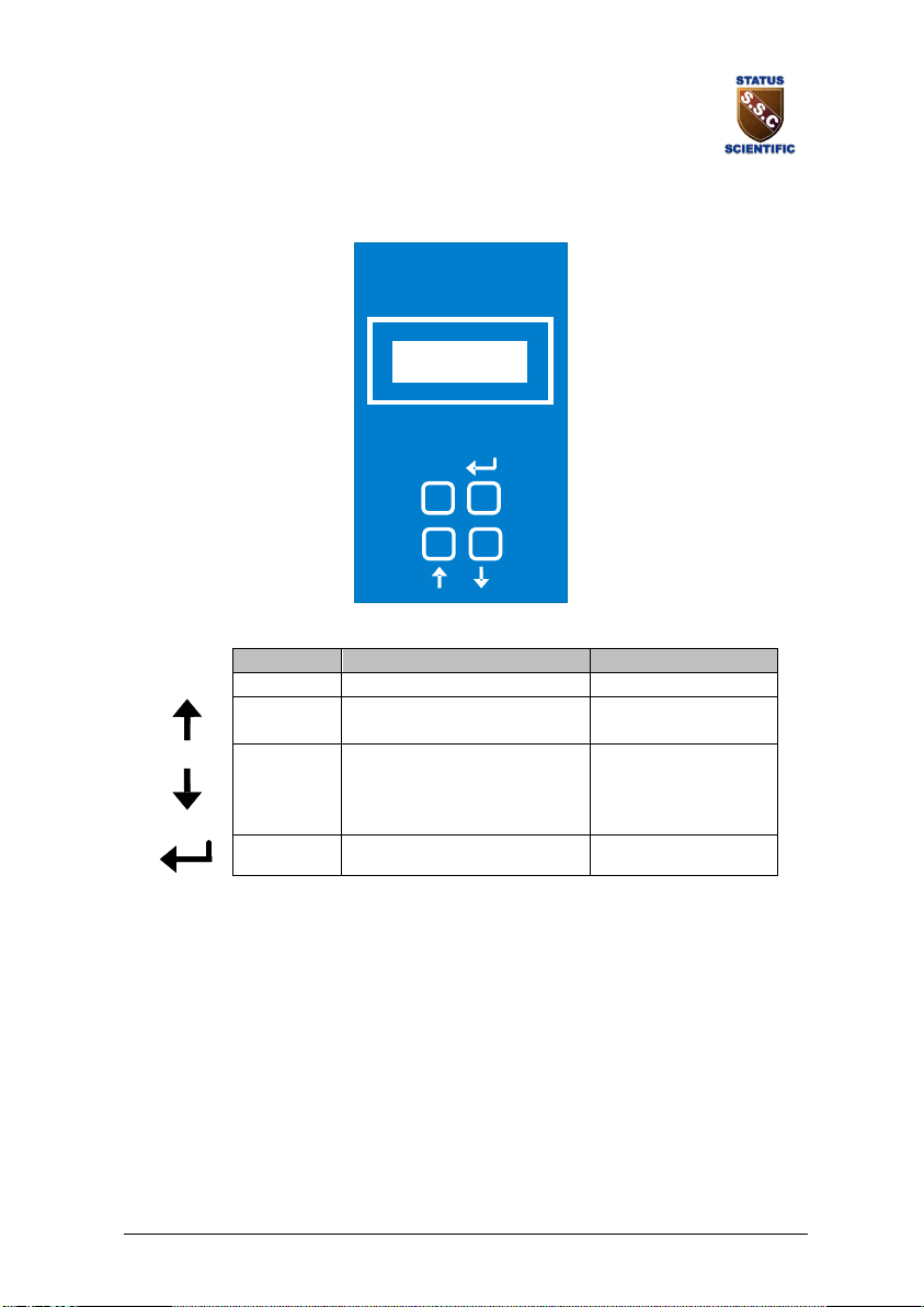
The menu system featured within the keypad calibration unit allows all
calibration and configuration activities to be performed.
MENU
The keypad has the following functionality:
Button
Function
Alternate Function
MENU
MENU
Open / Close Menu
Password
UP
Next / Increase
1
DOWN
Previous / Decrease
2
ENTER
Accept selection
3
This section of the manual discusses how the available menu options can be
accessed, how the associated parameter may be changed via the selected
menu option and what effect the change to the parameter has on the
operation of the FGD4, FGD10B or similar gas detector that uses the
keypad.
Note: It is important that the FGD4, FGD10B and PC192-NT are correctly
configured for the sensor in use, prior to performing any feature available in
the menu system.
Page 6

STATUS SCIENTIFIC CONTROLS
Calibration / Configuration Keypad
FGD4, FGD10B and PC192-NT Gas Detector
TD18/026
Issue: 2 Change Note:
1778
Page 6
1.2. Menu Mode Selection
The external Calibration / Configuration Keypad is used in its simplest form to calibrate
the sensor for zero or gas drift.
It may also be used to configure the gas detector.
The following features are available via the Calibration / Configuration Keypad menu
system: -
Menu Option
E : 01 – Sensor Zero
E : 02 – Sensor Span
E : 03 – Sensor FSD
E : 04 – Output Zero (4mA)
E : 05 – Output Span (20mA)
E : 09 – Diagnostics
E : 17 – Sensor Gain
E : 19 – Positive zero suppression
E : 20 – Negative zero suppression
E : 25 – Zero temperature compensation +ve
E : 34 – Span temperature compensation +ve
E : 35 – Span temperature compensation -ve
E : 36 – Zero temperature compensation -ve
E : 52 – Turn On/ OFF the manual calibration
E : 77 – Firmware version
The menu options are selected as follows:
• Press the MENU button, E: 1 appears on the display.
• Press or until the required menu option is displayed, see
following options.
• Press to select the menu option.
• To exit the menu press MENU.
While the instrument is in menu mode – any data displayed on the screen will alternate
between the menu number and the reading.
Note: On selecting a menu option the display will show one of the following:
1) E:xx Action only
2) Ed:xx Value to be Edited
3) LI:xx Select value from a list, there may only be 1 item in the
list.
In some cases the value may be edited after selection,
i.e. E:3
Page 7

STATUS SCIENTIFIC CONTROLS
Calibration / Configuration Keypad
FGD4, FGD10B and PC192-NT Gas Detector
TD18/026
Issue: 2 Change Note:
1778
Page 7
1.2.1. E : 01 – Sensor Zero
Refer to section 2.1.1. for sensor calibration details.
1.2.2. E : 02 – Sensor Span
Refer to section 2.1.2. for sensor calibration details.
1.2.3. E : 03 – Sensor Fsd
This Feature sets the FSD of the instrument. It must be matched to the
sensor.
• Press MENU to open the menu system.
• Using the or buttons, select menu option: E:3
• Press .
• Using the or buttons, change the display to the required
setting.
• Press to store the new value.
Note: Pressing the MENU button rather than the button
exits without any change.
• Press MENU to close the menu system.
1.2.4. E : 04 – Output Zero (4mA)
Refer to section 2.2.1. for output calibration details.
1.2.5. E : 05 – Output Span (20mA)
Refer to section 2.2.2. for output calibration details.
Page 8
STATUS SCIENTIFIC CONTROLS
Calibration / Configuration Keypad
FGD4, FGD10B and PC192-NT Gas Detector
TD18/026
Issue: 2 Change Note:
1778
Page 8
1.2.6. E : 08 – Sensor Type
There are two types of sensor that can be fitted, either an oxygen or electrochemical.
• Press MENU to open the menu system.
• Using the or buttons, select menu option: E:8
• Press .
• Using the or buttons, set the required sensor type.
• Press to store the new value.
Note: Pressing the MENU button rather than the button
exits without any change.
• Press MENU to close the menu system.
Note: This option will restore the sensor to the factory default values. The user
must set all
1.2.7. E : 09 – Engineer diagnostics
This feature is a view-only feature. No configuration changes are possible
from within this menu.
The information is for use of Status Scientific Controls personnel.
• From the menu system select menu option: E: 9 and press
.
• Using the or buttons, display the required setting. The
displayed values are as follows:
E : 90 Reading
E : 92 Current sensor temperature °C
E : 93 Active sensor A to D counts
E : 94 Reference sensor A to D counts
E : 95 Fractional Absorbance
E : 96 Status flags
Note: gas detectors may not display all the above options.
Page 9
STATUS SCIENTIFIC CONTROLS
Calibration / Configuration Keypad
FGD4, FGD10B and PC192-NT Gas Detector
TD18/026
Issue: 2 Change Note:
1778
Page 9
1.2.8. E : 17 – Sensor gain, Toxic sensors
This feature is used to set up the gain of the electronics to match the range
and sensor type. The gain setting can be between 0 and 31, where 0 is the
lowest gain and 31 is the highest gain.
The gain setting should be kept as low as possible. The gain settings are
based on the first stage having a gain of 61.6 (1 + 2000 / 33).
Typical settings:
Sensor Type
Max output
(nA/ppm)
Make
Range
Resolution
(display)
Units
Gain
H2S
180
Ind. Sci.
0-50
0.05
ppm
10
H2S
180
Ind. Sci.
0-100
0.1
ppm 6 H2S
180
Ind. Sci.
0-200
0.5
ppm 2 H2S
180
Ind. Sci.
0-500
1
ppm 0 H2S(L)
450
Surecell
0-50
0.05
ppm 4 H2S(L)
450
Surecell
0-100
0.1
ppm 2 H2S(L)
450
Surecell
0-300
0.5
ppm 0 H2S(4HS+)
850
City Tech
0-50
0.05
ppm 2 H2S(4HS+)
850
City Tech
0-250
0.1
ppm 0 CO
90
Ind. Sci.
0-200
0.2
ppm 6 CO
90
Ind. Sci.
0-500
0.5
ppm 2 CO
90
Ind. Sci.
0-1000
1
ppm 0 CO(M)
85
Surecell
0-200
0.2
ppm 6 CO(M)
85
Surecell
0-500
0.5
ppm 2 CO(M)
85
Surecell
0-1000
1
ppm 0 CO(4CF+)
85
City Tech
0-200
0.2
ppm 6 CO(4CF+)
85
City Tech
0-500
0.5
ppm 2 CO(4CF+)
85
City Tech
0-1000
1
ppm 0 NH3(100SE)
160
Sensoric
0-100
0.1
ppm
6
NH3(1000SE)
12
Sensoric
0-1000
1
ppm
10
SO2(4S)
600
City Tech
0-20
0.02
ppm
15
Note: NH3 Sensors can have a T
90
of several minutes when protected by a sinter
and should not be used in time sensitive applications. Low levels may not
be detected.
Page 10
STATUS SCIENTIFIC CONTROLS
Calibration / Configuration Keypad
FGD4, FGD10B and PC192-NT Gas Detector
TD18/026
Issue: 2 Change Note:
1778
Page 10
1.2.9. E : 19 – Positive Zero Suppression
This option is used to allow the user to suppress small amounts of positive
sensor zero drift. The setting can be set between 0 and 10% of the sensor
range as set by the FSD value.
• Press MENU to open the menu system.
• Using the or buttons, select menu option: E:19
• Press .
• Using the or buttons, set the required zero suppression
value.
• Press ENTER to store the new value.
Note: Pressing the MENU button rather than the R button
exits without any change.
• Press MENU to close the menu system.
1.2.10. E : 20 – Negative Zero Suppression
This option is used to allow the user to suppress small amounts of negative
sensor zero drift. The setting can be set between 0 and -10% of the sensor
range as set by the FSD value.
• Press MENU to open the menu system.
• Using the or buttons, select menu option: E:20
• Press .
• Using the or buttons, set the required zero suppression
value.
• Press to store the new value.
Note: Pressing the MENU button rather than the button
exits without any change.
• Press MENU to close the menu system.
Page 11

STATUS SCIENTIFIC CONTROLS
Calibration / Configuration Keypad
FGD4, FGD10B and PC192-NT Gas Detector
TD18/026
Issue: 2 Change Note:
1778
Page 11
1.2.11. E : 25 – Positive Zero Temperature Compensation
This option has no effect on the sensor version 1.0.3
1.2.12. E : 34 – Positive Span Temperature Compensation
This option has no effect on the sensor version 1.0.3
1.2.13. E : 35 – Negative Span Temperature Compensation
This option has no effect on the sensor version 1.0.3
1.2.14. E : 36 – Positive Zero Temperature Compensation
This option has no effect on the sensor version 1.0.3.
1.2.15. E : 52 – Enable / Disable calibration buttons
This option is only available for the infrared sensor
1.2.16. E : 77 – Firmware Version
The FGD4, FGD10b and ST196-NT Firmware version is displayed.
• Press MENU to close the menu system.
Page 12
STATUS SCIENTIFIC CONTROLS
Calibration / Configuration Keypad
FGD4, FGD10B and PC192-NT Gas Detector
TD18/026
Issue: 2 Change Note:
1778
Page 12
2. CALIBRATION
2.1. Sensor Calibration
This feature allows the sensor to be calibrated. Ensure that the correct
sensor type is selected in the configuration prior to calibration. Refer to
section 1.2. for details of the menu system operation.
Note: if the password is in operation then the user will be prompted with
PASS when ever the menu key is pressed. Pressing the MENU key
again will result in the restricted user access, i.e. only the zero and
span options will be available. Entering the correct password will
give access to the full menu facility.
2.1.1. Sensor Zero
• From the menu system select menu option: E: 1 and press
.
• Ensure the sensor is in a zero-gas environment.
Note: Where a purging gas has to be applied, use a flow rate of
between 500 and 1000cc/min. Allow sufficient time for the
sensor to respond.
• Press to zero the sensor, ‘– – – –‘ will be displayed to
confirm the sensor zero has been performed.
Note: Pressing MENU rather than exits the zero feature
without performing the calibration.
• Press MENU to close the menu system.
Page 13

STATUS SCIENTIFIC CONTROLS
Calibration / Configuration Keypad
FGD4, FGD10B and PC192-NT Gas Detector
TD18/026
Issue: 2 Change Note:
1778
Page 13
2.1.2. Sensor Span
Always zero the sensor prior to performing a span operation.
• From the menu system select menu option: E: 2 and press
.
• Apply a known concentration of gas (applicable to sensor type)
at a flow rate of between 500 and 1000cc/min. Allow time for
the sensor to respond.
• Using the and buttons, set the reading to that of the
calibration gas level.
• Press to span the sensor, ‘– – – –‘ will be displayed to
confirm the sensor span has been performed.
Note: pressing MENU rather than ENTER exits the span
feature without performing the calibration.
Wait until the reading is stable, if necessary press again
to span the sensor.
• Press MENU to close the menu system.
• Turn off and disconnect the calibration gas.
Note: NH3 Sensors can take several minutes to respond. Low levels may not
be detected.
Page 14
STATUS SCIENTIFIC CONTROLS
Calibration / Configuration Keypad
FGD4, FGD10B and PC192-NT Gas Detector
TD18/026
Issue: 2 Change Note:
1778
Page 14
2.2. Analogue Output Calibration
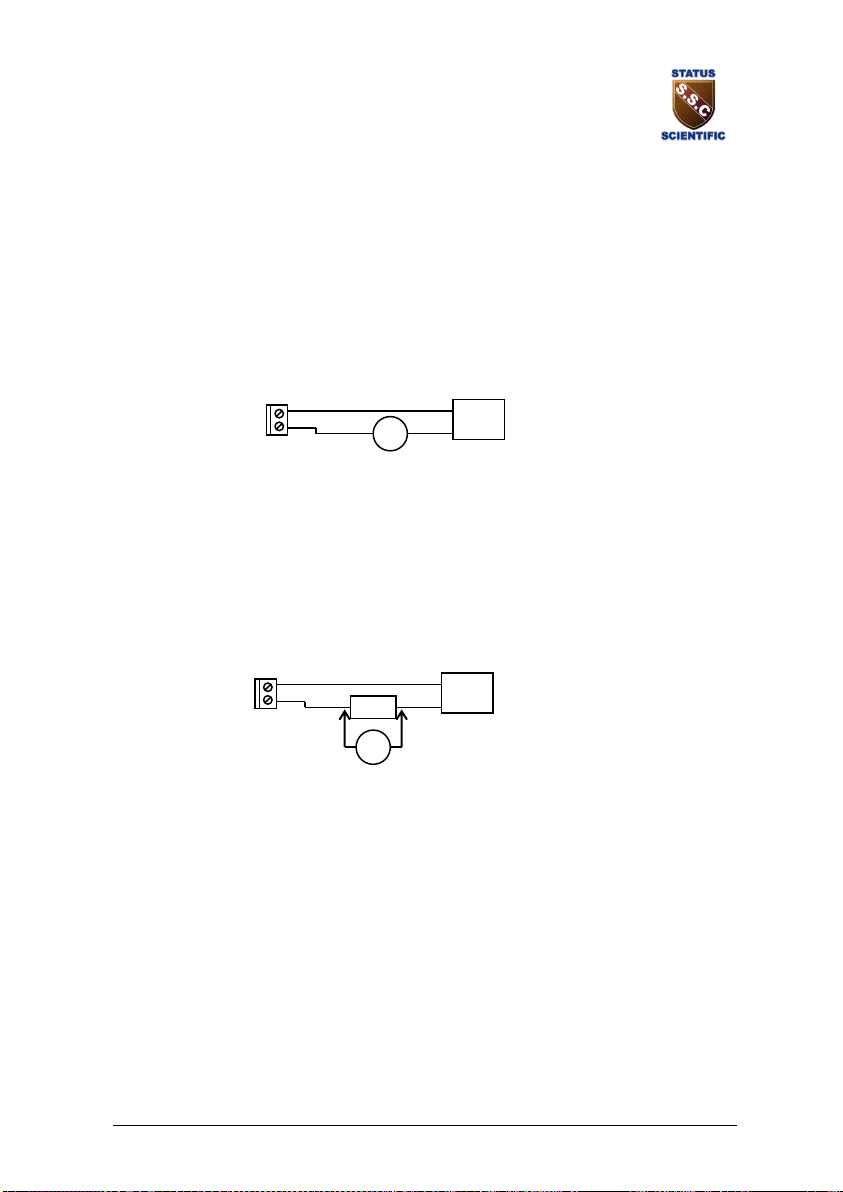
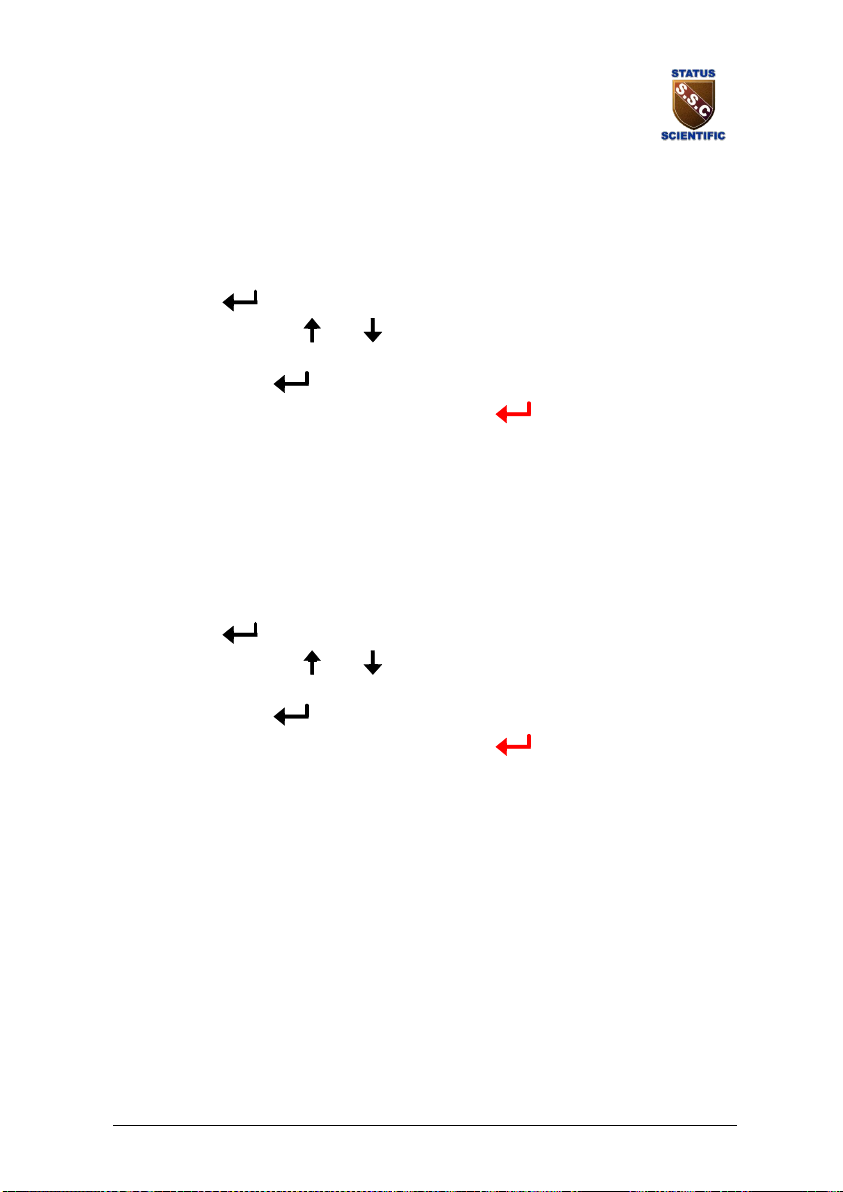
The analogue output is that of a current source. In order to calibrate the
output it is necessary to monitor the output signal. This can be performed in
one of two ways:
Current measurement:
Connect an ammeter (or multimeter set to measure current in the mA range)
in series with the analogue output.
Advantage: Direct measurement of output.
Disadvantage: The analogue output has to be disconnected to allow the
connection of the meter.
Voltage measurement:
Permanently connect a 10R resistor in series with the analogue output.
When calibration is required, connect a voltmeter (or multimeter set to
measure voltage in the mV range) across the 10R resistor.
Advantage: No need to disturb wiring between Gas detector and
control unit.
Disadvantage: Measurement accuracy dependent upon resistor tolerance.
–
+
Analogue Output
(4 – 20mA)
Control
Unit
mA
+
Meter range:
0.004A – 0.020A
4mA – 20mA
–
+
Analogue Output
(4 – 20mA)
Control
Unit
10R
mV
+
Meter range:
0.04V – 0.20V
40mV – 200mV
Page 15
STATUS SCIENTIFIC CONTROLS
Calibration / Configuration Keypad
FGD4, FGD10B and PC192-NT Gas Detector
TD18/026
Issue: 2 Change Note:
1778
Page 15
2.2.1. Analogue Output Zero
• Monitor the current sourced from the analogue output of the
Gas detector using a suitable method.
• From the menu system select menu option: E: 4 and press
.
• Using the and buttons; adjust the output to the required
level (4mA or 40mV).
• Press .
Note: Pressing MENU rather than exits the zero feature
without performing the calibration.
• Press MENU to close the menu system.
2.2.2. Analogue Output Span
Always zero the analogue output prior to performing a span operation.
• From the menu system select menu option: E: 5 and press
(button 4).
• Using the and buttons; adjust the output to the required
level, usually 20 mA.
• Press .
Note: Pressing MENU rather than exits the span feature
without performing the calibration.
• Press MENU to close the menu system.
Page 16

STATUS SCIENTIFIC CONTROLS
Calibration / Configuration Keypad
FGD4, FGD10B and PC192-NT Gas Detector
TD18/026
Issue: 2 Change Note:
1778
Page 16
3. LOW BATTERY
3.1. Low Battery Indication
There is no low battery warning to say that the battery level in the keypad is
low. Look out for the following which are indications that the batteries level is
low.
• The display on the keypad starting to fade
• Changes in the reading on the control panel connected to the
detector. This can change as soon as the keypad is plugged
into the detector.
 Loading...