

Page 1

STATUS SCIENTIFIC CONTROLS
Issue:
18
Date:
1/1/24
Firmware:
V2.9.yy
Installation, Commissioning &
Routine Gas Testing Manual
Gas Detector
Type FGD10A
Oxygen - Toxic Gases
(Relay version)
Page 2

Page 3
Page 4

Page 5

Installation, Commissioning & Routine Gas Testing
FGD10A Oxygen / Toxic Gas Detector
TD18/002
Issue:
19
Change Note:
2033
Page 4
CONTENTS
1. FIRMWARE REVISION ....................................................................... 6
2. PACKAGE CONTENTS ...................................................................... 7
3. SCOPE OF THE MANUAL .................................................................. 7
4. DESCRIPTION .................................................................................... 8
4.1. RELAYS .................................................................................... 10
4.2. ALTERNATIVE GAS TYPES ........................................................... 10
5. INSTALLATION ................................................................................ 11
5.1. CABLE ENTRIES ......................................................................... 12
5.2. MOUNTING AND TERMINAL ACCESS ............................................. 12
5.3. FGD10A CONNECTIONS ............................................................ 14
5.4. POWER SUPPLY ........................................................................ 14
5.5. ANALOGUE OUTPUT ................................................................... 15
5.6. RS232 OUTPUT ........................................................................ 15
6. COMMISSIONING ............................................................................. 16
6.1. APPLYING POWER ...................................................................... 16
6.2. INDICATORS .............................................................................. 16
7. INITIAL GAS TESTING ..................................................................... 17
7.1. ZERO GAS ................................................................................. 17
7.2. TEST GAS ................................................................................. 19
7.2.1. Gas connection points .......................................................................... 19
7.2.2. Sampling time ....................................................................................... 20
7.2.3. Suggested calibration gas levels. ......................................................... 20
8. SOFTWARE FEATURES .................................................................. 21
8.1. MENU MODE SELECTION ............................................................ 22
8.1.1. E : 1 – Sensor Zero ............................................................................... 23
8.1.2. E : 2 – Sensor Span .............................................................................. 23
8.1.3. E : 3 – Sensor FSD ............................................................................... 23
8.1.4. E : 4 – Output Zero (4mA) .................................................................... 23
8.1.5. E : 5 – Output Span (20mA) ................................................................. 23
8.1.6. E : 6 – Decimal Places .......................................................................... 24
8.1.7. E : 7 – Firmware Version ...................................................................... 24
8.1.8. E : 8 – Sensor Selection ....................................................................... 25
8.1.9. E : 9 – Engineer diagnostics ................................................................. 26
8.1.10. E : 13 – Relay 1 ............................................................................... 26
8.1.11. E : 14 – Relay 2 ............................................................................... 27
8.1.12. E : 15 – Alarm Level 1 ..................................................................... 27
8.1.13. E : 16 – Alarm Level 2 ..................................................................... 28
8.1.14. E : 19 – Positive Zero Suppression................................................. 28
8.1.15. E : 20 – Negative Zero Suppression ............................................... 29
8.1.16. E : 21 – Toxic Sensor Bias .............................................................. 29
8.1.17. E : 28 – Firmware update ................................................................ 30
8.1.18. E : 29 – Relay 3 ............................................................................... 30
8.1.19. E : 30 – Password ........................................................................... 31
8.1.20. E : 31 – Warm-up timer ................................................................... 31
8.1.21. E : 47 – Analogue Output FSD ....................................................... 32
Page 6

Installation, Commissioning & Routine Gas Testing
FGD10A Oxygen / Toxic Gas Detector
TD18/002
Issue:
19
Change Note:
2033
Page 5
9. CALIBRATION .................................................................................. 33
9.1. SENSOR CALIBRATION ............................................................... 33
9.1.1. Sensor Zero .......................................................................................... 33
9.1.2. Sensor Span ......................................................................................... 34
9.2. ANALOGUE OUTPUT CALIBRATION .............................................. 35
9.2.1. Analogue Output Zero........................................................................... 36
9.2.2. Analogue Output Span.......................................................................... 36
10. ERROR CODES ................................................................................ 37
10.1. EXAMPLE 1 100 PPM TOXIC SENSOR ........................................... 37
10.2. EXAMPLE 2 5000 PPM TOXIC SENSOR ......................................... 37
11. COMMUNICATIONS PROTOCOL .................................................... 38
11.1. HARDWARE CONNECTIONS ......................................................... 38
11.2. CONTROL BYTE CONSTANTS ...................................................... 38
11.3. FRAME STRUCTURE ................................................................... 39
11.4. VARIABLES ................................................................................ 39
11.5. READING A VARIABLE ................................................................. 40
11.5.1. Read example - read live data ........................................................ 41
11.6. WRITING A VARIABLE ................................................................. 42
12. ROUTINE GAS TESTING .................................................................. 43
13. SENSOR REPLACEMENT ................................................................ 44
13.1. OXYGEN / TOXIC SENSOR ........................................................... 44
14. FUSES .............................................................................................. 52
15. SPECIFICATION ............................................................................... 53
16. DIMENSIONS .................................................................................... 54
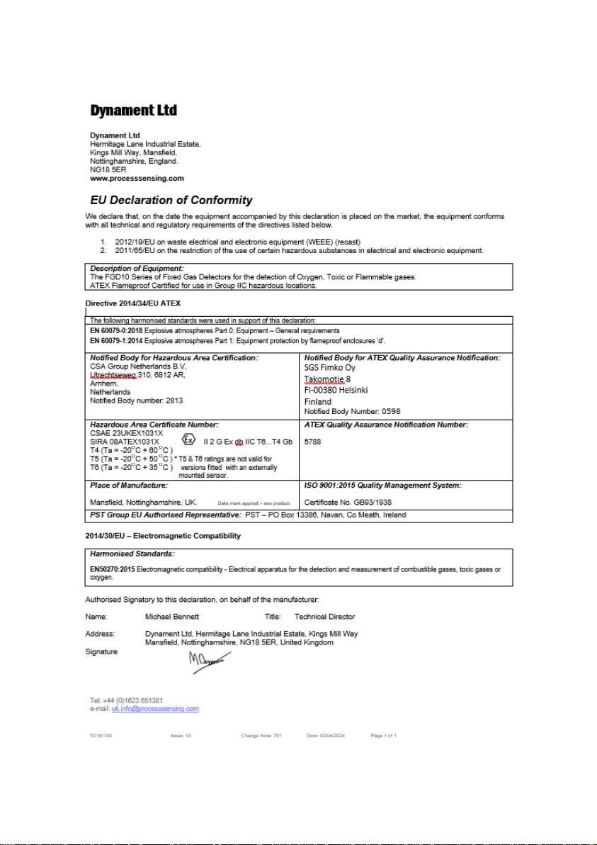
17. CERTIFICATION ............................................................................... 55
Page 7

Installation, Commissioning & Routine Gas Testing
FGD10A Oxygen / Toxic Gas Detector
TD18/002
Issue:
19
Change Note:
2033
Page 6
1. FIRMWARE REVISION
Page 8

Installation, Commissioning & Routine Gas Testing
FGD10A Oxygen / Toxic Gas Detector
TD18/002
Issue:
19
Change Note:
2033
Page 7
2. PACKAGE CONTENTS
The FGD10A is supplied in a box containing the following items:-
Description
Stock No
FGD10A Oxygen / Toxic Gas Detector
Magnetic pen
Installation manual
Calibration certificate
Optional:-
Weather guard
3. SCOPE OF THE MANUAL
This manual relates specifically to the version of the FGD10A gas detector
with the following features:-
• An Oxygen or Toxic sensor for the detection of various gases.
• Output signals in the form of 4 to 20mA and RS232 communications.
• Three control relays each fitted with a single set changeover contacts.
Page 9
Installation, Commissioning & Routine Gas Testing
FGD10A Oxygen / Toxic Gas Detector
TD18/002
Issue:
19
Change Note:
2033
Page 8
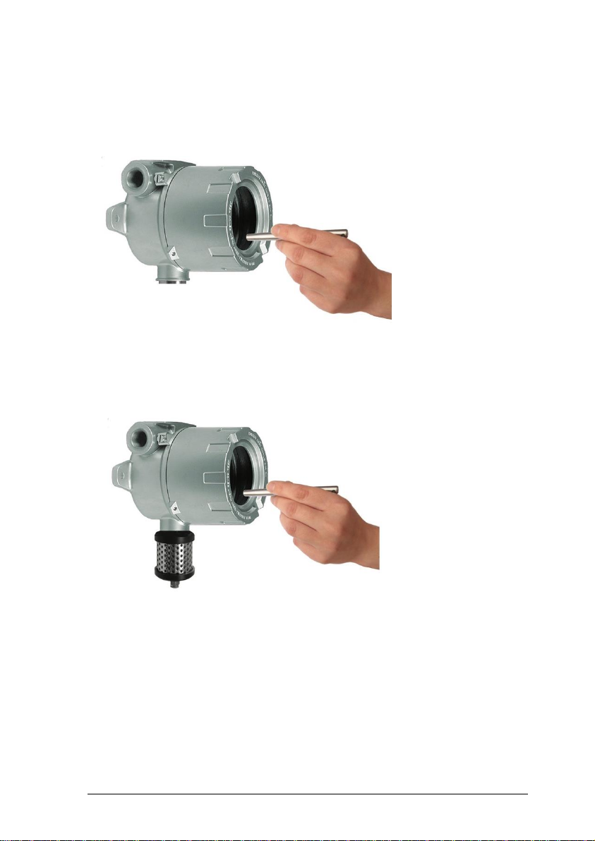
Description
FGD10A GAS DETECTOR
FGD10A GAS DETECTOR FITTED WITH
PROTECTIVE WEATHERGUARD
Page 10

Installation, Commissioning & Routine Gas Testing
FGD10A Oxygen / Toxic Gas Detector
TD18/002
Issue:
19
Change Note:
2033
Page 9
The FGD10A is an explosion protected ATEX and IECEx certified fixed gas
detector for use in potentially explosive atmospheres. The unit may be
optionally fitted with a protective weather guard as shown in the photograph.
IMPORTANT – When used in hostile environments (e.g. oil platforms
where the instrument is exposed to salt spray or diesel) it is
recommended that the FGD10A is always fitted with its protective
weather guard. The weather guard is attached with tamperproof screws
to ensure that it is not inadvertently removed.
The unit comprises an instrument housing having two cable gland entries
and containing the connection terminals, electronics and display window.
The housing containing the gas sensor has an M27 thread and is screwed
into the bottom of the unit. The sensor housing itself is a certified component
and must not be removed in service.
Behind the display window are:-
• A 4-digit LCD display
• Four magnetically operated switches that are activated through the
display window using a magnetic pen that is supplied with the unit.
• LED indicators for POWER, ALARM & KEY PRESS
The magnetically operated switches allow the unit to be calibrated
whilst power is still applied without the need to remove the cover from
the unit.
The main electrical features of the unit are:-
• Power supply – 12 to 24 volts dc (non-intrinsically safe)
• Analogue output – 4 to 20mA dc
• RS232 communications output.
• Relay contact outputs for Alarm 1, Alarm 2 and Fault.
• Gland entry threads available – 20mm, ½” or ¾” NPT
Page 11

Installation, Commissioning & Routine Gas Testing
FGD10A Oxygen / Toxic Gas Detector
TD18/002
Issue:
19
Change Note:
2033
Page 10
3.1. Relays
The FGD10A relay version has 3 factory-fitted relays. Each provides a set of
voltage free changeover contacts to perform the following control functions:-
• Alarm Level 1
• Alarm Level 2
• Fault
Versions without relays fitted are also available.
The self-adhesive label on the outer surface of the enclosure indicates
whether or not the relays are fitted as shown below:-
3.2. Alternative gas types
Versions of the FGD10A are available for detection of other gases, fitted with
any of the following sensor types:-
• Infrared (for detecting hydrocarbons and carbon dioxide)
• Pellistor (for detecting hydrogen and hydrocarbons)
GAS DETECTOR TYPE FGD10
CONTROL RELAYS FITTED
GAS DETECTOR TYPE FGD10
NO CONTROL RELAYS FITTED
Page 12

Installation, Commissioning & Routine Gas Testing
FGD10A Oxygen / Toxic Gas Detector
TD18/002
Issue:
19
Change Note:
2033
Page 11
4. INSTALLATION
It is important that the correct cable and gland types are used when installing
the FGD10A in a hazardous location.
The cable entry devices and blanking elements of unused apertures shall be
of a certified flameproof type, suitable for the conditions of use and correctly
installed.
With the use of conduit, a suitable certified sealing device such as a stopping
box with compound shall be provided immediately at the entrance to the
flameproof enclosure.
In order to prevent dangerous overloading of the FGD10A gas detector, it is
important that the installer observes the relay contact rating and ensures that
external circuits connected to the relay contacts are suitably protected from
exceeding that rating and associated cabling is adequately rated and suitably
installed.
Guidance on the correct installation of systems is provided by EN60079-14:
2014. It is the responsibility of the installer to ensure compliance with the
relevant standards.
To ensure effective gas detection, the FGD10A must be located at a height
appropriate to the density of the target gas relative to air. For example,
Methane (relative density 0.55) is lighter than air and so it will tend to
accumulate at a high level within a confined space. Whereas Petroleum
(relative density 2.8) is heavier than air and it will tend to accumulate at
around ground level.
Page 13

Installation, Commissioning & Routine Gas Testing
FGD10A Oxygen / Toxic Gas Detector
TD18/002
Issue:
19
Change Note:
2033
Page 12
Cable entries
The cable entry threads are 20mm, ½” or ¾” NPT female.
The FGD10A enclosure is manufactured from die cast aluminium. Therefore,
the use of glands, conduit fittings and blanks made from brass should be
avoided because if moisture is present, bi-metallic corrosion may occur due
to the chemical reaction between the two materials.
Glands and fittings plated with nickel, tin or zinc will provide improved
protection but in harsh environments the use of stainless steel is
recommended.
When connecting the cores inside the unit it is beneficial to use pointed-nose
pliers to carefully guide the cable cores from the cable entries at the rear of
the enclosure towards the pcb mounted terminal connections situated near to
the front of the enclosure.
4.1. Mounting and terminal access
The FGD10A should be mounted and secured using the mounting holes on
the main unit.
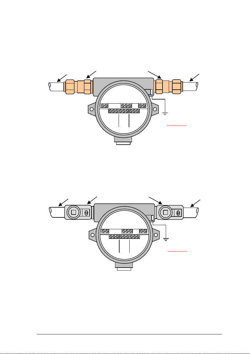
Figures 2 and 3 shows details of the FGD10A terminal connections – these
can be accessed as follows:-.
1. Switch OFF the supply to the FGD10A.
2. Release the grub screw located near the lip of the enclosure
cover.
Note: It is not necessary to completely remove the grub screw
to release the enclosure front cover.
3. Remove the enclosure front cover by rotating it several times in
an anti-clockwise direction.
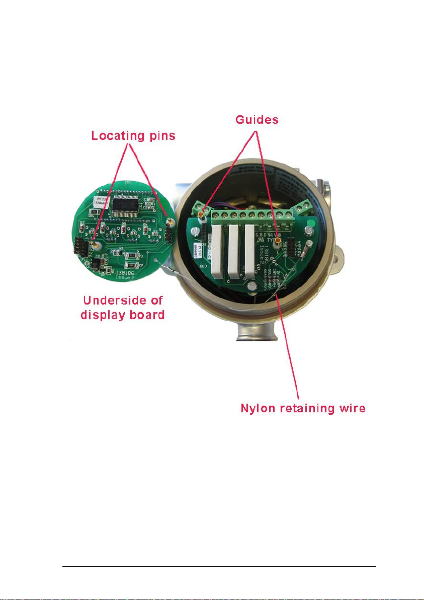
4. Unplug the top display board from within the enclosure by
pulling it forwards. The board is captivated by means of a nylon
wire in order to prevent it falling from the unit –take care to
ensure that the board is not damaged during installation. See
Figure 1.
5. The terminals can now be accessed.
Store the front cover such that it cannot be damaged or the thread
contaminated with dirt.
Page 14
Installation, Commissioning & Routine Gas Testing
FGD10A Oxygen / Toxic Gas Detector
TD18/002
Issue:
19
Change Note:
2033
Page 13
Figure 1 – Unplugging the display board for
connection purposes
Page 15
Installation, Commissioning & Routine Gas Testing
FGD10A Oxygen / Toxic Gas Detector
TD18/002
Issue:
19
Change Note:
2033
Page 14
FGD10A connections
Figure 2 – Armoured Cable Gland Installation
Figure 3 – EEx d Conduit Installation
4.2. Power Supply
Important
Connect
enclosure
earth-point
to a high
integrity
earth
ATEX certified Ex d armoured
cable glands
- +
PSU
- +
Aout
0V
Rx
Tx
RS232
Armoured cable
Armoured cable
Mount vertically
as shown
N/O
COM
N/C
Relay 1
Alarm 1
N/O
COM
N/C
Relay 2
Alarm 2
N/O
COM
N/C
Relay 3
Fault
Important
Connect
enclosure
earth-point
to a high
integrity
earth
ATEX Certified compound-filled
conduit seals (stopping boxes)
- +
PSU
- +
Aout
0V
Rx
Tx
RS232
Conduit
Conduit
Mount vertically
as shown
N/O
COM
N/C
Relay 1
Alarm 1
N/O
COM
N/C
Relay 2
Alarm 2
N/O
COM
N/C
Relay 3
Fault
Page 16
Installation, Commissioning & Routine Gas Testing
FGD10A Oxygen / Toxic Gas Detector
TD18/002
Issue:
19
Change Note:
2033
Page 15
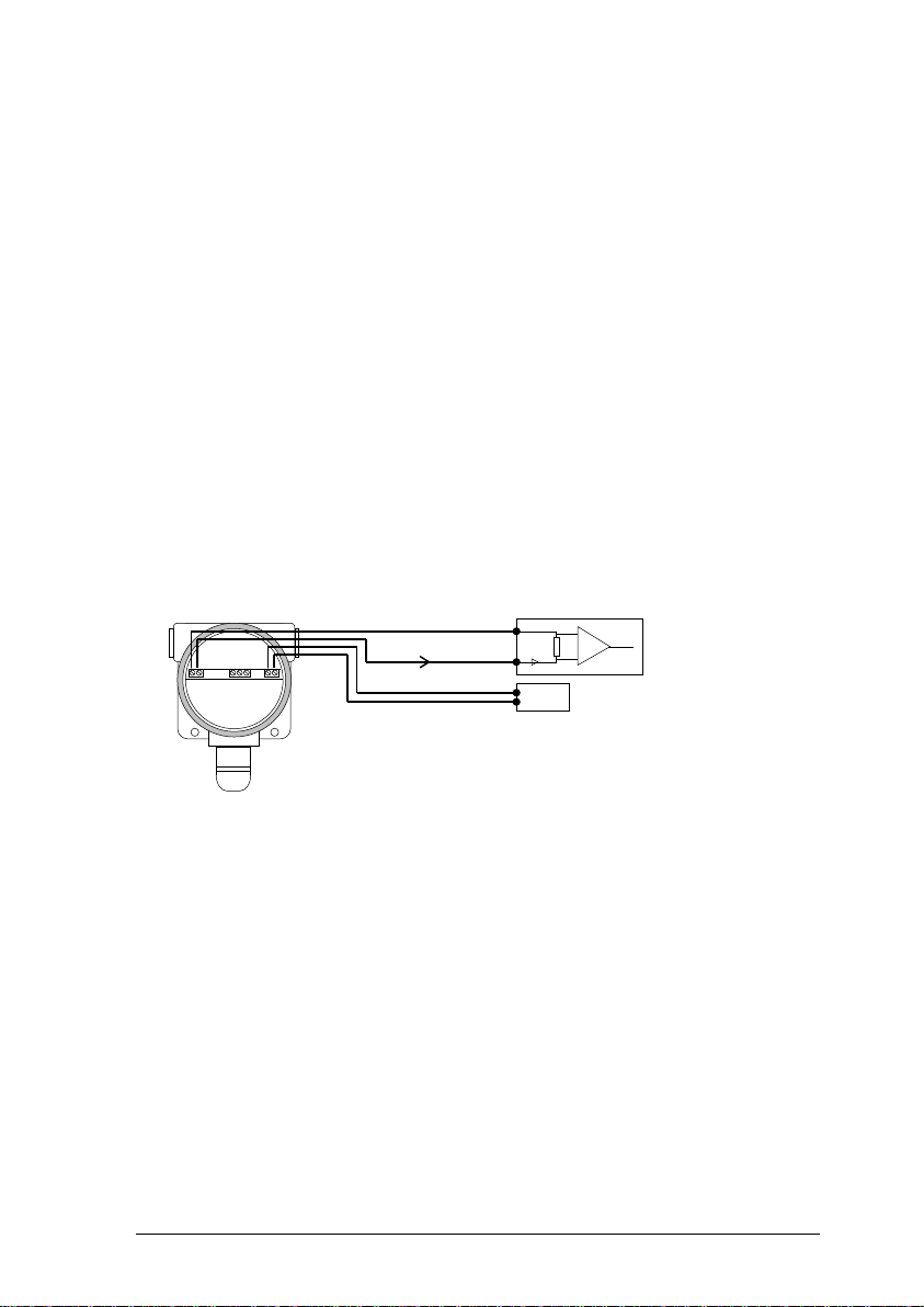
The FGD10A is powered from an 12 – 24 volt dc, 5 W maximum output
supply. This may be either:-
a) An independent supply powering one or more units.
b) A supply that is an integral part of a control card within a monitoring
panel.
4.3. Analogue Output
The analogue output provides a means of indicating to external equipment
(e.g. data loggers, remote displays, control cards) the gas levels currently
being detected by the system. The output is in the form of the industry
standard 4 to 20mA current source.
The analogue output is factory set such that 4mA represents zero gas and
20mA represents the full scale gas level of the FGD10A.
Figure 4 – Analogue Output
4.4. RS232 Output
This output is designed to be compatible with a PC fitted with an RS232
serial communications port. Suitable software is available for installation in
the PC. Contact Status Scientific Controls Ltd for details.
Note - The amplifier and
power supply may be
contained on the same
control card.
FGD10
0V
A+
0V
12-24V DC
Control
Unit
I (4-20mA)
PSU
Page 17

Installation, Commissioning & Routine Gas Testing
FGD10A Oxygen / Toxic Gas Detector
TD18/002
Issue:
19
Change Note:
2033
Page 16
Commissioning
Following completion of the installation:-
a) Replace the top display board using the locating pins on the
underside of the board to ensure that it makes connection with the
remainder of the electronics - see Figure 1.
b) Ensure that the front cover has not been contaminated with dirt -
paying particular attention to the thread. Replace the cover by
rotating it several times clockwise until it reaches its limit then
secure using the grub screw – do not over tighten.
4.5. Applying power
Once the installation is complete and the covers are secure then power can
be applied. The power source should be between 12 and 24 volts dc.
When power is first applied to the FGD10A, an initialisation procedure is
performed as follows:
All segments on the LCD are shown
:
8.8:8.8
The software version is displayed
:
1.0.0
The manufacturer code is displayed
:
SSCL
The sensor type is displayed
:
O2
The detected gas level present is displayed and the FGD10A becomes
operational.
4.6. Indicators
Three LED indicators are visible from the front panel of the instrument.
These are:
Colour
Identity
Operation
Red
Alarm
Illuminates when either alarm level has been reached.
Green
Power
Always ON when power is connected.
Yellow
Key press
Illuminates when the magnetic switches are operated.
Page 18

Installation, Commissioning & Routine Gas Testing
FGD10A Oxygen / Toxic Gas Detector
TD18/002
Issue:
19
Change Note:
2033
Page 17
Initial Gas Testing
FGD10A units are factory calibrated as detailed on the calibration certificate
supplied with the instrument. However, it is always advisable after installation
to confirm that the instrument reads zero with no gas present and responds
accurately when presented with an appropriate concentration of the target
gas.
The FGD10A display becomes operational within 60 seconds however, the
sensor should be allowed to stabilise for the period specified on the
associated calibration certificate before attempting to check the zero setting
and gas response.
4.7. Zero gas
With no gas present check that the instrument reads zero on the display *.
a) If the instrument reads zero then no adjustment is required and gas
response testing may now be carried out as described in Section 0
b) If the instrument does not read zero then adjustment of the zero setting
is required as described in Section 5.1.1. - Sensor Zero.
c) If the analogue signal is connected to an associated control panel,
confirm that when the FGD10A display reads zero, the control panel
display also reads zero or, adjust as necessary in accordance with the
control panel manufacturers’ instructions.
* Note – If there is the possibility of a background gas being present then zeroing of
the detector should be carried out using a test gas cylinder of air in nitrogen.
Page 19
Installation, Commissioning & Routine Gas Testing
FGD10A Oxygen / Toxic Gas Detector
TD18/002
Issue:
19
Change Note:
2033
Page 18
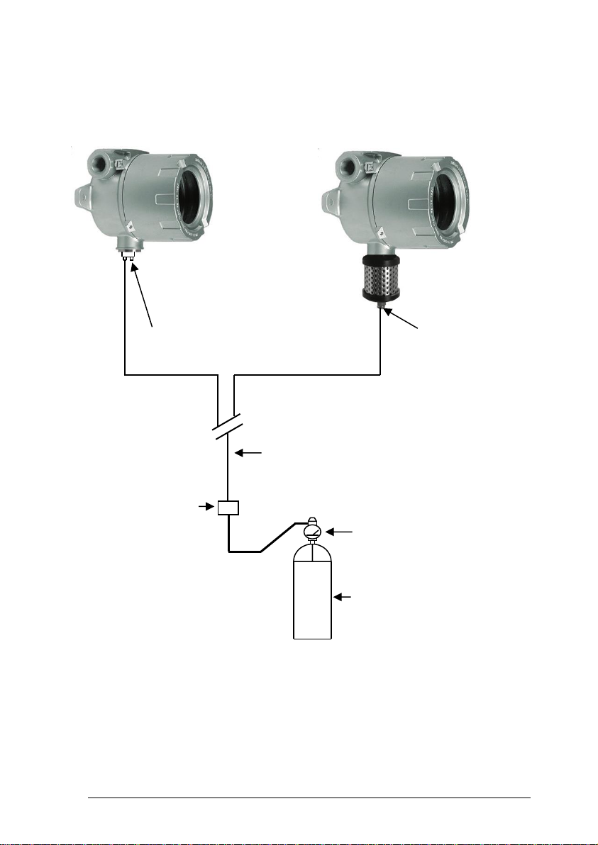
Figure 6 – Arrangement for Application of a Certified Test Gas
Certified
Test Gas
Cylinder
Remote
Sampling Point
6mm O.D.
Sampling Tube
Calibration
Adaptor
Metal sampling adaptor, Stock No. SS747
Without weatherguard
With weatherguard
Flow Regulator
(1 Litre/min)
Page 20

Installation, Commissioning & Routine Gas Testing
FGD10A Oxygen / Toxic Gas Detector
TD18/002
Issue:
19
Change Note:
2033
Page 19
Test gas
Figure 6 shows a typical arrangement for the application of a certified test
gas.
The purpose of the test gas response check is to confirm that that the
reading on the instrument corresponds with the test gas concentration.
a) If the instrument reads correctly then no adjustment is required.
b) If the analogue signal is connected to an associated control panel,
confirm that the reading corresponds with that on the FGD10A or adjust
as necessary in accordance with the control panel manufacturer’s
instructions.
c) If the above checks are satisfactory then the installation is now
complete.
d) If the instrument does not read correctly then adjustment of the sensor
span setting is required as described in Section 5.1.2. - Sensor Span.
4.7.1. Gas connection points
Certified test gas can be applied either:a). directly to the FGD10A via the appropriate sampling/calibration adaptor.
or
b). remotely, by connecting a test gas sampling tube to the appropriate
sampling/calibration adaptor and installing a test point at the remote end of
the tube.
Method b) avoids the need to gain direct access to the unit in order to carry
out routine gas testing. The sample tube should be taken to a convenient
point and sited such that the risk of contamination is minimised. A means
must be provided to ‘cap off’ the tube when not in use in order to prevent
blockage.
The weather guard is provided with a 6mm O.D. push in tube connector to
allow connection of a gas sampling tube. Firstly, remove the blanking plug by
depressing the coloured plastic ring whilst pulling on the plug; now push in
the gas sampling tube. The standard fitting is a push fit connector for 6mm
O.D tubing. The connector is screwed into a 1/8” BSP thread; other fittings
are available on request.
Page 21

Installation, Commissioning & Routine Gas Testing
FGD10A Oxygen / Toxic Gas Detector
TD18/002
Issue:
19
Change Note:
2033
Page 20
Where a weather guard is not fitted, the use of a sampling adaptor (Stock
No. SS747) is required in order to present the gas to the FGD10A sensor.
4.7.2. Sampling time
Apply the test gas and allow a sufficient time for the sample to reach the gas
detector. The response time will vary according to the length of the sampling
tube.
4.7.3. Suggested calibration gas levels.
Oxygen sensor:
Zero 100% N2.
Span 20.9%O2.
Toxic sensor:
Zero gas free air, must contain oxygen.
Span 50% of range.
Page 22
Installation, Commissioning & Routine Gas Testing
FGD10A Oxygen / Toxic Gas Detector
TD18/002
Issue:
19
Change Note:
2033
Page 21
Software Features
The menu system featured within the FGD10A allows all calibration and
configuration activities to be performed.
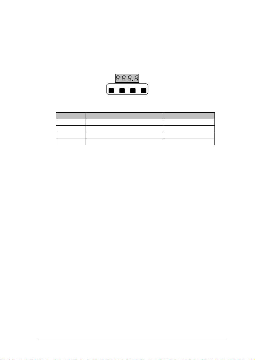
The magnetic keypad has the following functionality:
Button
Function
Alternate Function
MENU
Open / Close Menu
PASSword
UP
Next / Increase
1
DOWN
Previous / Decrease
2
ENTER
Accept selection
3
This section of the manual discusses how the available menu options can be
accessed, how the associated parameter may be changed via the selected
menu option and what effect the change to the parameter has on the
operation of the FGD10A.
The FGD10A incorporates magnetically operated switches to allow nonintrusive operation of the menu system. To ‘press’ the switch requires
movement of the stylus pen over the appropriate button. The key press LED
will light to indicate that the button press is being detected. In some
instances it may be necessary to hold the pen over the button for sufficient
time to allow the microcontroller to determine the key that has been pressed.
Note:
It is important that that the FGD10A is correctly configured for the sensor in
use, prior to performing any feature available in the menu system.
Page 23
Installation, Commissioning & Routine Gas Testing
FGD10A Oxygen / Toxic Gas Detector
TD18/002
Issue:
19
Change Note:
2033
Page 22
4.8. Menu Mode Selection
The FGD10A uses a password system to restrict the end user from carrying
out certain changes that may compromise the use of the equipment.
Setting the password to zero will give the user access without compromise.
User password allows access to calibrate the sensor only.
Engineer password gives complete access and allows every aspect of the
system to be changed.
Note : The password is a pre-set six digit number which can be
obtained from Status Scientific Controls Ltd.
Several calibration modes exist in the FGD10A and these are accessible via
the instruments simple menu system. To select a calibration mode follow this
procedure:
• Press the MENU button, E: 1 appears on the display.
• Press UP or DOWN until the required menu option is
displayed.
• Press ENTER to select the calibration mode.
• To exit the menu press MENU.
While the instrument is in menu mode – any data displayed on the screen will
alternate between the cal number and the reading.
The following features are available via the ‘FGD10A’ menu system: -
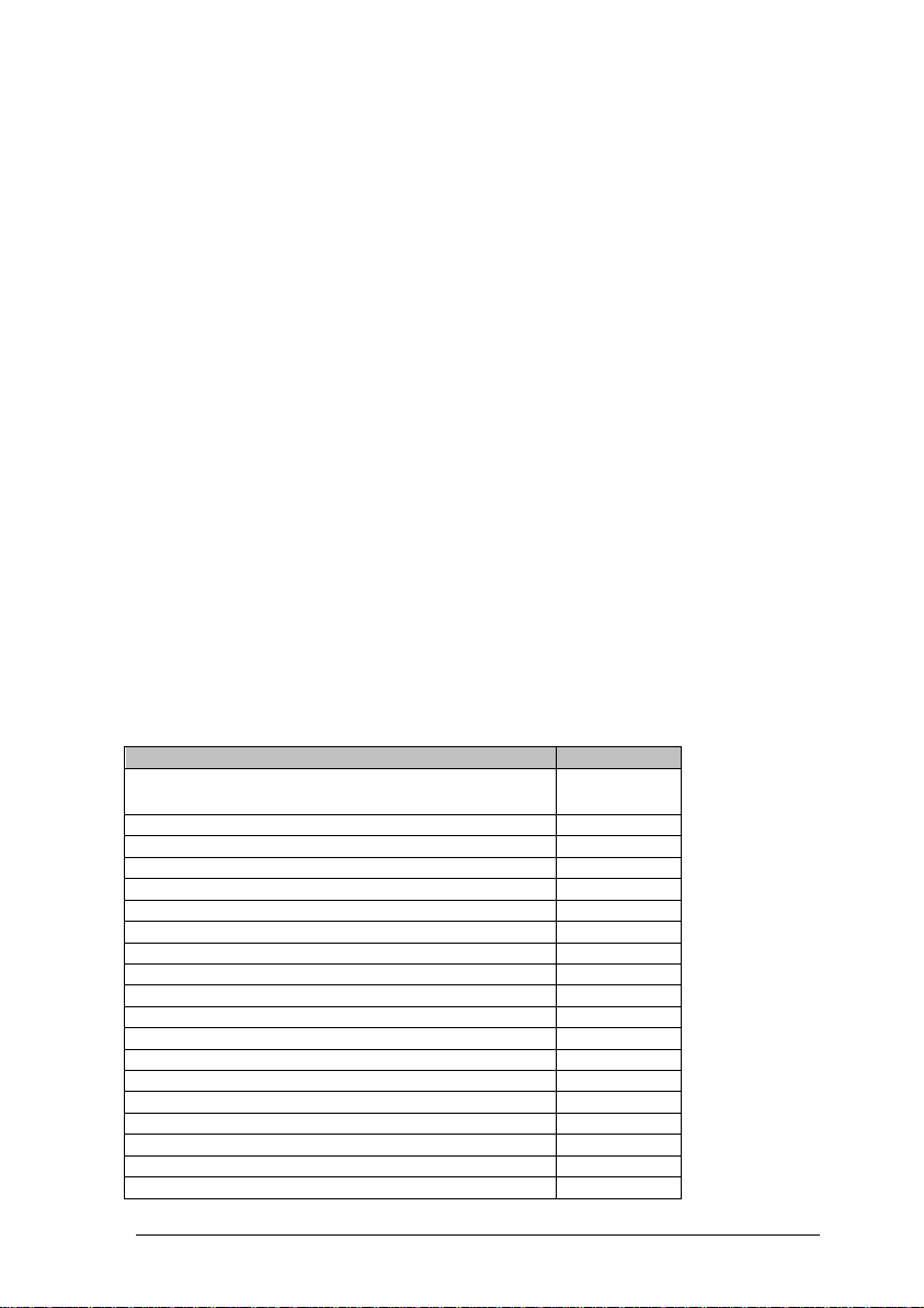
Menu Option
Section
E : 1 – Sensor Zero
0
E : 2 – Sensor Span
4.8.2.
E : 2 – Sensor Span
4.8.3.
E : 4 – Output Zero (4mA)
4.8.4.
E : 5 – Output Span (20mA)
4.8.5.
E : 6 – Decimal Places
4.8.6.
E : 7 – Firmware version
4.8.7.
E : 9 – Engineer diagnostics
4.8.9.
E : 13 – Relay 1
4.8.10.
E : 14 – Relay 2
4.8.11.
E : 15 – Alarm Level 1
4.8.12.
E : 16 – Alarm Level 2
4.8.13.
E : 19 – Positive Zero Suppression
4.8.14.
4.8.15.
E : 27 – Hysteresis
4.8.16.
E : 28 – Firmware Update
4.8.17.
E : 29 – Relay 3
4.8.18.
E : 30 – Password
4.8.19.
E : 31 – Warm-up timer
4.8.20.
Page 24

Installation, Commissioning & Routine Gas Testing
FGD10A Oxygen / Toxic Gas Detector
TD18/002
Issue:
19
Change Note:
2033
Page 23
E : 47 – Set the Dac analogue output FSD
4.8.21.
4.8.21.
4.8.1. E : 1 – Sensor Zero
Refer to section 5.1.1. for sensor calibration details.
4.8.2. E : 2 – Sensor Span
Refer to section 5.1.2. for sensor calibration details.
4.8.3. E : 3 – Sensor FSD
The sensor measuring range is set by this menu.
• From the menu system select menu option: E: 3 and press
ENTER.
• Using the INCrease and DECrease buttons, select the required
value.
• Press ENTER.
Note: Pressing MENU instead of ENTER will exit the menu
without changing the value.
• Press MENU to close the menu system.
Note: changing the FSD must be used with caution. The setting must be
within the capability of the sensor.
4.8.4. E : 4 – Output Zero (4mA)
Refer to section 5.2.1. for output calibration details.
4.8.5. E : 5 – Output Span (20mA)
Refer to section 5.2.2. for output calibration details.
Page 25

Installation, Commissioning & Routine Gas Testing
FGD10A Oxygen / Toxic Gas Detector
TD18/002
Issue:
19
Change Note:
2033
Page 24
4.8.6. E : 6 – Decimal Places
The number of decimal places that are used to display the detected gas
levels can be changed via this menu option.
• From the menu system select menu option: E: 6 and press
ENTER.
• Using the NEXT and PREVIOUS buttons, select the required
number of decimal places.
• Press ENTER.
Note: Pressing MENU instead of ENTER will exit the menu
without changing the number of decimal places to which the
gas level will be displayed.
• Press MENU to close the menu system.
Note that when the sensor type is first selected, the optimum number of
decimal places for a given sensor type and range is automatically selected.
Increasing the number of decimal places to which detected gas levels are
displayed does not increase the sensitivity or accuracy of the instrument and
in some cases may degrade the instruments perceived stability.
4.8.7. E : 7 – Firmware Version
The Firmware version is displayed in the form X.Xyy, where X is numerical
and y is a letter.
• Press MENU to close the menu system.
Page 26

Installation, Commissioning & Routine Gas Testing
FGD10A Oxygen / Toxic Gas Detector
TD18/002
Issue:
19
Change Note:
2033
Page 25
4.8.8. E : 8 – Sensor Selection
This menu option allows the sensor type to be manually selected. The
available sensor options are listed below:
OPTION
TYPE
RANGE
COMMENTS
O2
Electro
chemical
0-25 %v/v
Oxygen
ELT1
Electro
chemical
0-5 ppm
Toxic
ELT2
Electro
chemical
0-10 ppm
Toxic
ELT3
Electro
chemical
0-20 ppm
Toxic
ELT4
Electro
chemical
0-50ppm
Toxic
ELT5
Electro
chemical
0-200ppm
Toxic
ELT6
Electro
chemical
0-500ppm
Toxic
ELT7
Electro
chemical
0-1000ppm
Toxic
ELT8
Electro
chemical
0-9999ppm
Toxic
The sensor type is selected as follows:
• From the menu system select menu option: E: 8 and press
ENTER.
• Using the NEXT and PREVIOUS buttons, select the required
sensor.
• Press ENTER
Note: Pressing ENTER whilst in menu option E: 8 will reset the
factory defaults for the displayed sensor. A calibration must be
performed even if the sensor type was not changed.
• Press MENU to close the menu system.
Note: It is important that the sensor selected via this menu option
corresponds to the sensor that is installed. Incorrect settings here may result
in the inability of the instrument to detect gas.
Page 27

Installation, Commissioning & Routine Gas Testing
FGD10A Oxygen / Toxic Gas Detector
TD18/002
Issue:
19
Change Note:
2033
Page 26
4.8.9. E : 9 – Engineer diagnostics
This feature is a view-only feature. No configuration changes are possible
from within this menu.
The information is for use of Status Scientific Controls personnel.
• From the menu system select menu option: E: 9 and press
ENTER.
• Using the NEXT button, display the required setting. The
displayed values are as follows:
E : 90 Gas level
E : 94 Active sensor A to D counts
• Press MENU to close the menu system.
4.8.10. E : 13 – Relay 1
The unit is fitted with a relay that is operated in conjunction with the alarm
level. The user can select if the relay is normally Energized, E’ or normally
de-energised, ‘d’ when the unit is not in an alarm condition.
• From the menu system select menu option: E: 13 and press
ENTER.
• The display will show the following:
E:r Normally energized, rising alarm
d:r Normally de-energized, rising alarm
E:F Normally energized, falling alarm
d:F Normally de-energized, falling alarm
• The mode of operation can be changed by pressing the UP
button.
• Press ENTER to accept the new relay mode of operation.
Note: Pressing MENU instead of ENTER leaves the unit
without change.
• Press MENU to return the instrument to its standard mode of
operation.
Page 28

Installation, Commissioning & Routine Gas Testing
FGD10A Oxygen / Toxic Gas Detector
TD18/002
Issue:
19
Change Note:
2033
Page 27
4.8.11. E : 14 – Relay 2
The unit is fitted with a relay that is operated in conjunction with the alarm
level. The user can select if the relay is normally Energized, ‘E’ or normally
de-energised, ‘d’ when the unit is not in an alarm condition.
• From the menu system select menu option: E: 14 and press
ENTER.
• The display will show the following:
E:r Normally energized, rising alarm
d:r Normally de-energized, rising alarm
E:F Normally energized, falling alarm
d:F Normally de-energized, falling alarm
• The mode of operation can be changed by pressing the UP
button.
• Press ENTER to accept the new relay mode of operation.
Note: Pressing MENU instead of ENTER leaves the unit
without change.
• Press MENU to return the instrument to its standard mode of
operation.
4.8.12. E : 15 – Alarm Level 1
The gas level that will cause Relay 1 to change state is set via this menu
option.
• From the menu system select menu option: E: 15 and press
ENTER.
• Using the UP and DOWN buttons, adjust the displayed reading
so that it matches the desired alarm set point.
• Press ENTER to accept the new alarm level.
Note: Pressing MENU instead of ENTER aborts the feature.
• Press MENU to return the instrument to its standard mode of
operation.
Page 29

Installation, Commissioning & Routine Gas Testing
FGD10A Oxygen / Toxic Gas Detector
TD18/002
Issue:
19
Change Note:
2033
Page 28
4.8.13. E : 16 – Alarm Level 2
The gas level that will cause Relay 2 to change state is set via this menu
option.
• From the menu system select menu option: E: 16 and press
ENTER.
• Using the UP and DOWN buttons, adjust the displayed reading
so that it matches the desired alarm set point.
• Press ENTER to accept the new alarm level.
Note: Pressing MENU instead of ENTER aborts the feature.
• Press MENU to return the instrument to its standard mode of
operation.
4.8.14. E : 19 – Positive Zero Suppression
This option is used to allow the user to suppress small amounts of positive
sensor zero drift. The setting can be set between 0 and 10% of the sensor
range as set by the FSD value.
• Press MENU to open the menu system.
• Using the NEXT and PREVIOUS buttons, select menu option:
E:19
• Press ENTER.
• Using the INCREASE and DECREASE buttons, set the
required zero suppression value.
• Press ENTER to store the new value.
Note: Pressing the MENU button rather than the ENTER button
exits without any change.
• Press MENU to close the menu system.
Page 30

Installation, Commissioning & Routine Gas Testing
FGD10A Oxygen / Toxic Gas Detector
TD18/002
Issue:
19
Change Note:
2033
Page 29
4.8.15. E : 20 – Negative Zero Suppression
This option is used to allow the user to suppress small amounts of negative
sensor zero drift. The setting can be set between 0 and 10% of the sensor
range as set by the FSD value.
• Press MENU to open the menu system.
• Using the NEXT and PREVIOUS buttons, select menu option:
E:20
• Press ENTER.
• Using the INCREASE and DECREASE buttons, set the
required zero suppression value.
• Press ENTER to store the new value.
Note: Pressing the MENU button rather than the ENTER button
exits without any change.
• Press MENU to close the menu system.
•
4.8.16. E : 21 – Toxic Sensor Bias
This option sets the bias voltage to match the sensor fitted.
Available options are:
b0 no bias
b250 250 mV bias
b300 300 mV bias
The normal level is 0, no bias.
Page 31

Installation, Commissioning & Routine Gas Testing
FGD10A Oxygen / Toxic Gas Detector
TD18/002
Issue:
19
Change Note:
2033
Page 30
4.8.17. E : 28 – Firmware update
Use this menu option to place the FGD10A module in the programming
mode whereby the internal firmware can be updated.
• Press the MENU to open the menu system.
• Using the NEXT and PREVIOUS buttons, select menu option:
E:28
• Press ENTER.
• The display shows prog
• Press the MENU button. The displays shows boot
Note: the only way to exit out of this mode is to either remove the power or
program the device from the PC software.
See PC software manual to carry out the actual programming of the FGD10A
module.
4.8.18. E : 29 – Relay 3
The unit is fitted with a relay that is operated in conjunction with a fault
condition. The user can select if the relay is normally Energized, ‘E’ or
normally de-energised, ‘d’ when the unit is not in a fault condition.
• From the menu system select menu option: E: 29 and press
ENTER.
• The display will show the following:
E:r Normally energized, rising alarm
d:r Normally de-energized, rising alarm
E:F Normally energized, falling alarm
d:F Normally de-energized, falling alarm
• The mode of operation can be changed by pressing the UP
button.
• Press ENTER to accept the new relay mode of operation.
Note: Pressing MENU instead of ENTER leaves the unit
without change.
• Press MENU to return the instrument to its standard mode of
operation.
Page 32

Installation, Commissioning & Routine Gas Testing
FGD10A Oxygen / Toxic Gas Detector
TD18/002
Issue:
19
Change Note:
2033
Page 31
4.8.19. E : 30 – Password
Use this menu option to enable / disable the password feature.
Place the FGD10A in the password menu as follows:
• Press the MENU to open the menu system.
• Using the NEXT and PREVIOUS buttons, select menu option:
E:30
• Press ENTER.
• The display shows either On or OFF
• Press the UP button to select the desired setting.
• Press ENTER to accept the setting.
Note: Pressing MENU instead of ENTER leaves the unit
without change.
• Press MENU to return the instrument to its standard mode of
operation.
Note: if the password is in operation then the user will be prompted with
PASS when ever the menu key is pressed. Pressing the MENU key
again will result in the restricted user access, i.e. only the zero and
span options will be available. Entering the correct password will
give access to the full menu facility.
4.8.20. E : 31 – Warm-up timer
The sensor goes through a stabilisation period when power is first applied.
This option allows the user to adjust the time that is applied before readings
are displayed / transmitted.
• From the menu system select menu option: E: 31 and press
ENTER.
• Using the INCREASE and DECREASE buttons, set the
required warm-up time.
• Press ENTER to store the new value.
Note: Pressing the MENU button rather than the ENTER button
exits without any change.
Page 33

Installation, Commissioning & Routine Gas Testing
FGD10A Oxygen / Toxic Gas Detector
TD18/002
Issue:
19
Change Note:
2033
Page 32
4.8.21. E : 47 – Analogue Output FSD
This menu option allows the full-scale gas level to be selected that relates to
the 4 to 20 mA output.
• From the menu system select menu option: E: 47 and press
ENTER.
• Using the INCREASE and DECREASE buttons; adjust the FSD
to the required level.
• Press ENTER, ‘- - - - ‘will be displayed to indicate that the new
setting has been accepted.
Note: Pressing MENU instead of ENTER will exit the menu
without changing the FSD.
• Press MENU to close the menu system.
Page 34

Installation, Commissioning & Routine Gas Testing
FGD10A Oxygen / Toxic Gas Detector
TD18/002
Issue:
19
Change Note:
2033
Page 33
5. CALIBRATION
5.1. Sensor Calibration
This feature allows the sensor to be calibrated. Ensure that the correct
sensor type is selected in the configuration prior to calibration. Refer to
section 4.8. for details of the menu system operation.
Note: if the password is in operation then the user will be prompted with
PASS when ever the menu key is pressed. Pressing the MENU key
again will result in the restricted user access, i.e. only the zero and
span options will be available. Entering the correct password will
give access to the full menu facility.
5.1.1. Sensor Zero
• From the menu system select menu option: E: 1 and press
ENTER.
• Ensure the sensor is in a zero-gas environment.
Note: Where a purging gas has to be applied, use a flow rate
of between 500 and 1000cc/min. Allow sufficient time
for the sensor to respond.
• Press ENTER to zero the sensor, ‘– – – –‘ will be displayed to
confirm the sensor zero has been performed.
Note:
Pressing MENU rather than ENTER exits the zero feature
without performing the calibration.
• Press MENU to close the menu system.
Note:
The ZERO factor will be displayed momentarily on exit.
1 2 3 4
Page 35

Installation, Commissioning & Routine Gas Testing
FGD10A Oxygen / Toxic Gas Detector
TD18/002
Issue:
19
Change Note:
2033
Page 34
5.1.2. Sensor Span
Always zero the sensor prior to performing a span operation.
• From the menu system select menu option: E: 2 and press
ENTER.
• Apply a known concentration of gas (applicable to sensor type)
at a flow rate of between 500 and 1000cc/min. Allow time for
the sensor to respond.
• Using the UP and DOWN buttons, set the reading to that of the
calibration gas level.
• Press ENTER to span the sensor, ‘– – – –‘ will be displayed to
confirm the sensor span has been performed.
Note: pressing MENU rather than ENTER exits the span
feature without performing the calibration.
Wait until the reading is stable, if necessary press ENTER
again to span the sensor.
• Press MENU to close the menu system.
Note: the SPAN factor will be displayed momentarily on exit.
• Turn off and disconnect the calibration gas.
Page 36
Installation, Commissioning & Routine Gas Testing
FGD10A Oxygen / Toxic Gas Detector
TD18/002
Issue:
19
Change Note:
2033
Page 35
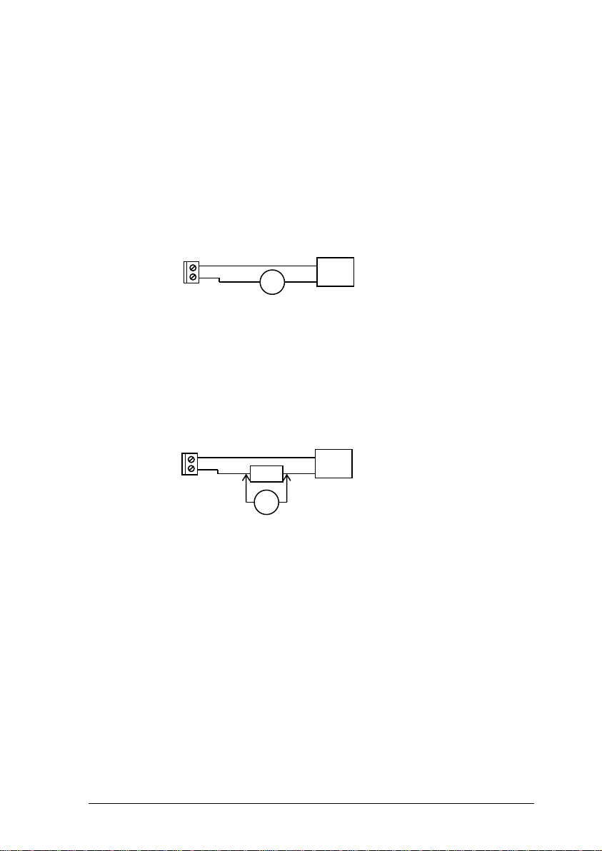
5.2. Analogue Output Calibration
The analogue output is that of a current source. In order to calibrate the
output it is necessary to monitor the output signal. This can be performed in
one of two ways:
Current measurement:
Connect an ammeter (or multimeter set to measure current in the mA range)
in series with the analogue output.
Advantage: Direct measurement of output.
Disadvantage: The analogue output has to be disconnected to allow the connection of
the meter.
Voltage measurement:
Permanently connect a 10R resistor in series with the analogue output.
When calibration is required, connect a voltmeter (or multimeter set to
measure voltage in the mV range) across the 10R resistor.
Advantage: No need to disturb wiring between FGD10A and control unit.
Disadvantage: Measurement accuracy dependent upon resistor tolerance.
–
+
FGD10
Analogue Output
(4 – 20mA)
Control
Unit
mA
Meter range:
0.004A – 0.020A
4mA – 20mA
–
+
FGD10
Analogue Output
(4 – 20mA)
Control
Unit
10R
mV
+
Meter range:
0.04V – 0.20V
40mV – 200mV
Page 37

Installation, Commissioning & Routine Gas Testing
FGD10A Oxygen / Toxic Gas Detector
TD18/002
Issue:
19
Change Note:
2033
Page 36
5.2.1. Analogue Output Zero
• Monitor the current sourced from the analogue output of the
FGD10A using a suitable method.
• From the menu system select menu option: E: 4 and press
ENTER.
• Using the INCREASE and DECREASE buttons; adjust the
output to the required level (4mA or 40mV).
• Press ENTER.
Note: Pressing the MENU button rather than the ENTER button
exits the zero feature without performing the calibration.
• Press the MENU button to close the menu system.
Note: The ZERO factor will be displayed momentarily on exit.
5.2.2. Analogue Output Span
Always zero the analogue output prior to performing a span operation.
• From the menu system select menu option: E: 5 and press ENTER.
• Using the INCREASE and DECREASE buttons; adjust the output to the
required level.
• Press ENTER button.
Note: Pressing the MENU button rather than the ENTER button exits
the span feature without performing the calibration.
• Press the MENU button to close the menu system.
Note: The ANALOGUE OUTPUT SPAN factor will be displayed
momentarily on exit.
Page 38

Installation, Commissioning & Routine Gas Testing
FGD10A Oxygen / Toxic Gas Detector
TD18/002
Issue:
19
Change Note:
2033
Page 37
6. ERROR CODES
The FGD10 Oxygen / Toxic Gas Detector has only 1 error code
ERROR_SENSOR_NEG_DRIFT = 2, the gas level is below -10% of the FSD.
6.1. Example 1 100 ppm toxic sensor
The error flag will be raised when the gas level is less than -10 ppm
6.2. Example 2 5000 ppm toxic sensor
The error flag will be raised when the gas level is less than -500 ppm
Page 39

Installation, Commissioning & Routine Gas Testing
FGD10A Oxygen / Toxic Gas Detector
TD18/002
Issue:
19
Change Note:
2033
Page 38
7. COMMUNICATIONS PROTOCOL
The communications protocol used by the FGD10A is used for
communications between devices connected via an RS232 connection at
19200 baud, 8 data bits 1 stop bit, no parity. This point-to-point, P2P,
protocol is a frame-based protocol.
7.1. Hardware connections
PC 9-way ‘D’ connector FGD10A connection
2 Tx
3 Rx
5 0V
PC 25-way ‘D’ connector FGD10A connection
3 Tx
2 Rx
7 0V
7.2. Control Byte Constants
The following control byte constants are used in the P2P protocol1.
Read,
RD
= 0x13
(00010011)
Data Link Escape,
DLE
= 0x10
(00010000)
Write,
WR
= 0x15
(00010101)
Acknowledge,
ACK
= 0x16
(00010110)
Negative Acknowledge,
NAK
= 0x19
(00011001)
Single Data Frame,
DAT
= 0x1A
(00011010)
End of Frame,
EOF
= 0x1F
(00011111)
Write Password 1,
WP1
= 0xE5
(11100101)
Write Password 2,
WP2
= 0xA2
(10100010)
Page 40

Installation, Commissioning & Routine Gas Testing
FGD10A Oxygen / Toxic Gas Detector
TD18/002
Issue:
19
Change Note:
2033
Page 39
7.3. Frame Structure
The start of a frame is indicated by a DLE byte followed by the type
of frame to follow (RD, WR, ACK, NAK, DAT). The end of frame is
indicated by a DLE byte followed by an EOF byte.
Note: Each of the constants has bit 4 set and so is slip-resistant
(i.e. if shifted this bit will be out of position). The values have a
Hamming Distance of 2 (each code is at least 2 bits different from
every other code).
Any DLE bytes that occur between a frame’s start and end are
prefixed with another DLE (byte-stuffing).
Following the EOF is a 16-bit checksum of the entire frame, each
byte is added to produce the checksum.
7.4. Variables
Each piece of accessible data on a device is referred to as a Variable. Each
variable is referenced by a Variable ID. A variable ID may be any number of
bytes long.
The available Variables and their corresponding Variable IDs depend on the
type of device, but here are a few examples for the FGD10A:-
General Configuration
0x00
Live Data
0x01
Zero Sensor
0x02
Span Sensor
0x03
Version Information
0x04
Firmware Update
0x05
The structure of the data returned in each variable usually depends both on
the type of device and the version of firmware running on the device.
Refer to device documentation for more information.
Page 41

Installation, Commissioning & Routine Gas Testing
FGD10A Oxygen / Toxic Gas Detector
TD18/002
Issue:
19
Change Note:
2033
Page 40
7.5. Reading a Variable
Send a read frame with the Variable ID to be read:
DLE
RD
var-
id
DLE
EOF
Csum
hi
Csum
lo
Byte
stuffing
Device response on success, where requested variable data < 255 bytes:
DLE
DAT
data-
len
data
DLE
EOF
Csum
hi
Csum
lo
Byte stuffing
Device response on failure:
DLE
NAK
reason
Where ‘reason’ is a single byte failure code, the meaning of which depends
on the device type, i.e.
Reason = 1, NotReadable,
Reason = 2, ReadOutOfRange
Page 42

Installation, Commissioning & Routine Gas Testing
FGD10A Oxygen / Toxic Gas Detector
TD18/002
Issue:
19
Change Note:
2033
Page 41
7.5.1. Read example - read live data
The following example is based on V4.x.xE where the data is either byte or
integer types only.
Send the following bytes:
DLE, RD, Variable ID, DLE, EOF, Checksum High byte, Checksum low
byte i.e.
0x10, 0x13, 0x01, 0x10, 0x1F, 0x00, 0x53
Device response on success:
DLE, DAT, Data length, Data, DLE, EOF, Checksum High byte, Checksum
low byte, i.e.
0x10 DLE
0x1A DAT
0x0D Data length
0x03 Version
0x01 Display mode
0x07 Sensor Type
0x00, 0x00 Gas reading (signed integer x 100) = 0
0xAE, 0x0B Current sensor temperature (signed integer x 100) =
29.9
0x92, 0x08 Active sensor signal (unsigned integer) = 2194
0xD7, 0x04 Reference sensor signal (unsigned integer) = 1239
0x10 DLE
0x1F EOF
0x02 Checksum high byte
0x9F Checksum low byte
Page 43

Installation, Commissioning & Routine Gas Testing
FGD10A Oxygen / Toxic Gas Detector
TD18/002
Issue:
19
Change Note:
2033
Page 42
7.6. Writing a Variable
Send a write frame with the Variable ID to be written:
DLE
WR
WP1
WP2
var-id
DLE
EOF
Csum
hi
Csum
lo
Byte stuffing
Device response on success:
DLE
ACK
Where data to write is < 255 bytes, send a DAT frame:
DLE
DAT
data-
len
data
DLE
EOF
Csum
hi
Csum
lo
Byte stuffing
Device response on write success:
DLE
ACK
Device response on write failure:
DLE
NAK
reason
Where ‘reason’ is a single byte failure code, the meaning of which depends
on the device type, i.e.
Reason = 1, NotWritable
Reason = 2, WriteOutOfRange
Reason = 3, BadDataLength
Reason = 4, IncorrectVersion
Page 44

Installation, Commissioning & Routine Gas Testing
FGD10A Oxygen / Toxic Gas Detector
TD18/002
Issue:
19
Change Note:
2033
Page 43
8. ROUTINE GAS TESTING
Refer to Figure 6 in section 0showing the arrangement for applying the test
gas to the FGD10A.
1. Before application of the test gas, check that the FGD10A reads zero
with no known gas present in the atmosphere. If necessary, carry out
adjustment of the zero setting as described in section 5.1.1.
2. Apply the test gas and allow a sufficient time for the sample to reach
the gas detector. The response time will vary according to the length
of the sampling tube.
3. Record the time taken for the gas detector to provide a reading of
90% (T90) of its final value (e.g. to reach 18.8% when using a 20.9%
O2 test gas after exposure to nitrogen). This reading should be
retained for future reference as it can provide an indication of the
health of the sinter (flame arrestor). This is situated in the base of
sensor housing and it is through this device that the gas passes in
order to reach the sensor itself. If necessary, carry out adjustment of
the span setting as described in section 5.1.2.
Carrying out the above procedure, and comparing the results with previous
readings, will confirm that the FGD10A is functioning correctly, both
physically and electrically. There is therefore no requirement for any further
maintenance other than to clean the display window as required.
In the unlikely event that the response time is seen to be increasing, when
comparing periodic readings, it is advisable to change the unit so that it can
be checked.
The period between carrying out routine gas testing shall be in accordance
with the customer’s specification.
Page 45
Installation, Commissioning & Routine Gas Testing
FGD10A Oxygen / Toxic Gas Detector
TD18/002
Issue:
19
Change Note:
2033
Page 44
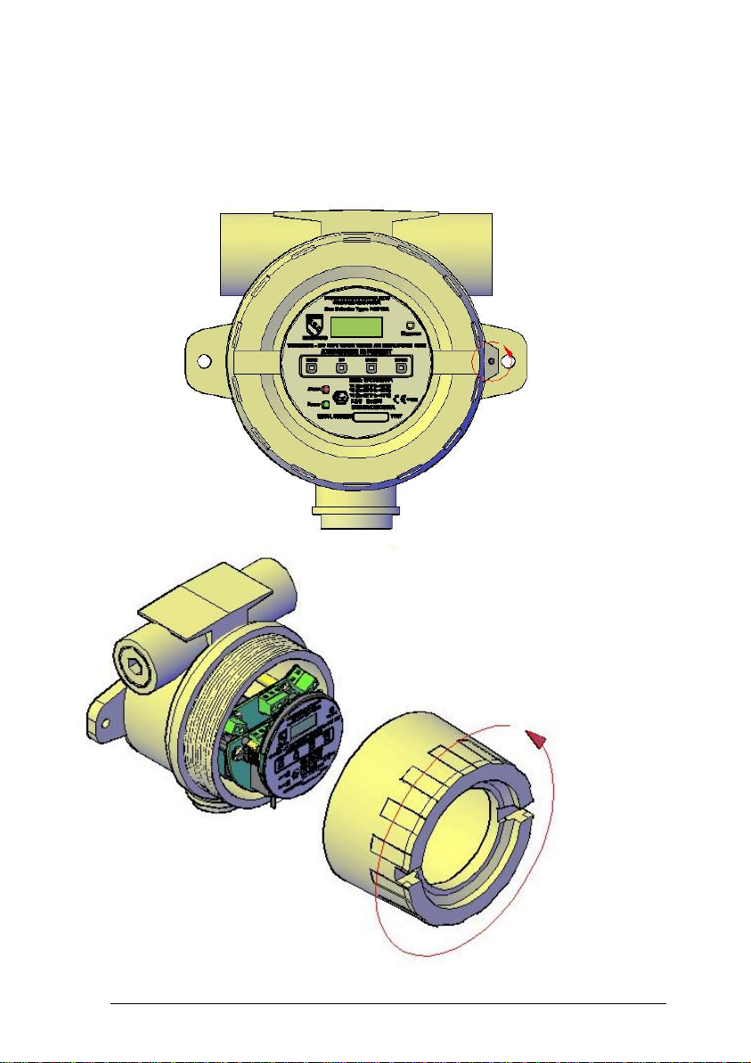
sensor replacement
8.1. Oxygen / Toxic sensor
Step1
Turn cover securing stud anti-clockwise to allow cover to open.
Step 2
Remove cover by rotating anti-clockwise
Page 46
Installation, Commissioning & Routine Gas Testing
FGD10A Oxygen / Toxic Gas Detector
TD18/002
Issue:
19
Change Note:
2033
Page 45
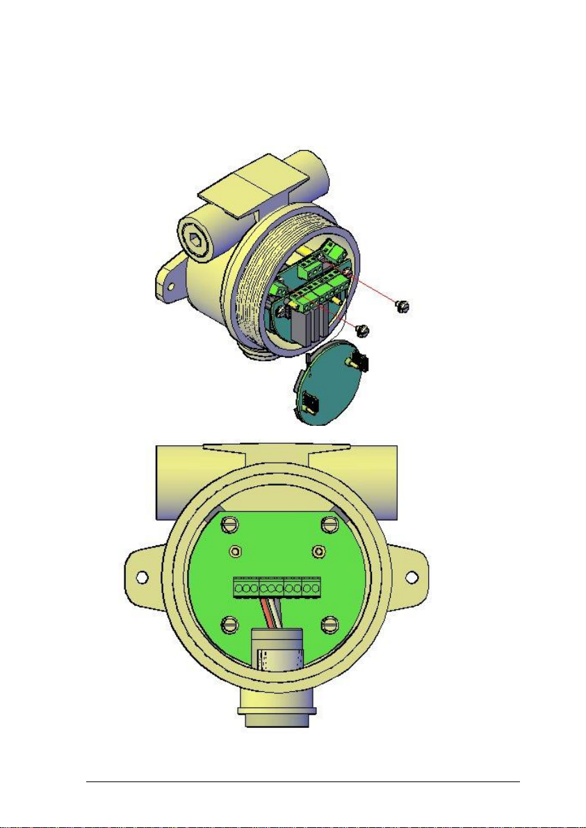
Step 3
Remove display board which can be left to dangle on its retaining wire.
Remove PCBs from the support pillars and the datamate cable from the
board left in the enclosure
Step 4
Remove wires from terminal block
Page 47

Installation, Commissioning & Routine Gas Testing
FGD10A Oxygen / Toxic Gas Detector
TD18/002
Issue:
19
Change Note:
2033
Page 46
Step 5
Remove sensor insert from FGD10A enclosure using extraction tool.
Page 48
Installation, Commissioning & Routine Gas Testing
FGD10A Oxygen / Toxic Gas Detector
TD18/002
Issue:
19
Change Note:
2033
Page 47
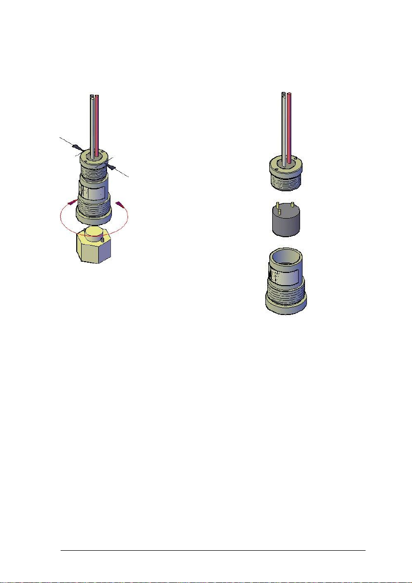
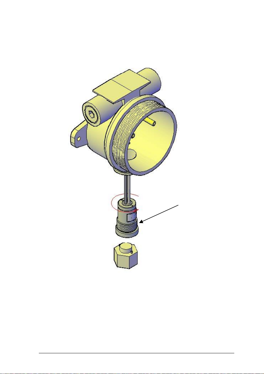
Step 6
Separate the two sensor insert components.
Once separated remove old sensor and replace with a new sensor and mate
the two component parts
Page 49
Installation, Commissioning & Routine Gas Testing
FGD10A Oxygen / Toxic Gas Detector
TD18/002
Issue:
19
Change Note:
2033
Page 48
Step 7
Apply Loctite 243 or a compound equal strength to the threads Insert the
sensor housing into the FGD10A enclosure using the insertion tool.
loctite
Page 50
Installation, Commissioning & Routine Gas Testing
FGD10A Oxygen / Toxic Gas Detector
TD18/002
Issue:
19
Change Note:
2033
Page 49
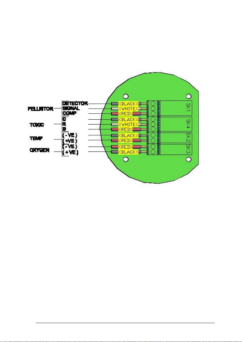
Step 8
Terminate the wires dependIing on which type of gas sensor is fitted.
Page 51
Installation, Commissioning & Routine Gas Testing
FGD10A Oxygen / Toxic Gas Detector
TD18/002
Issue:
19
Change Note:
2033
Page 50
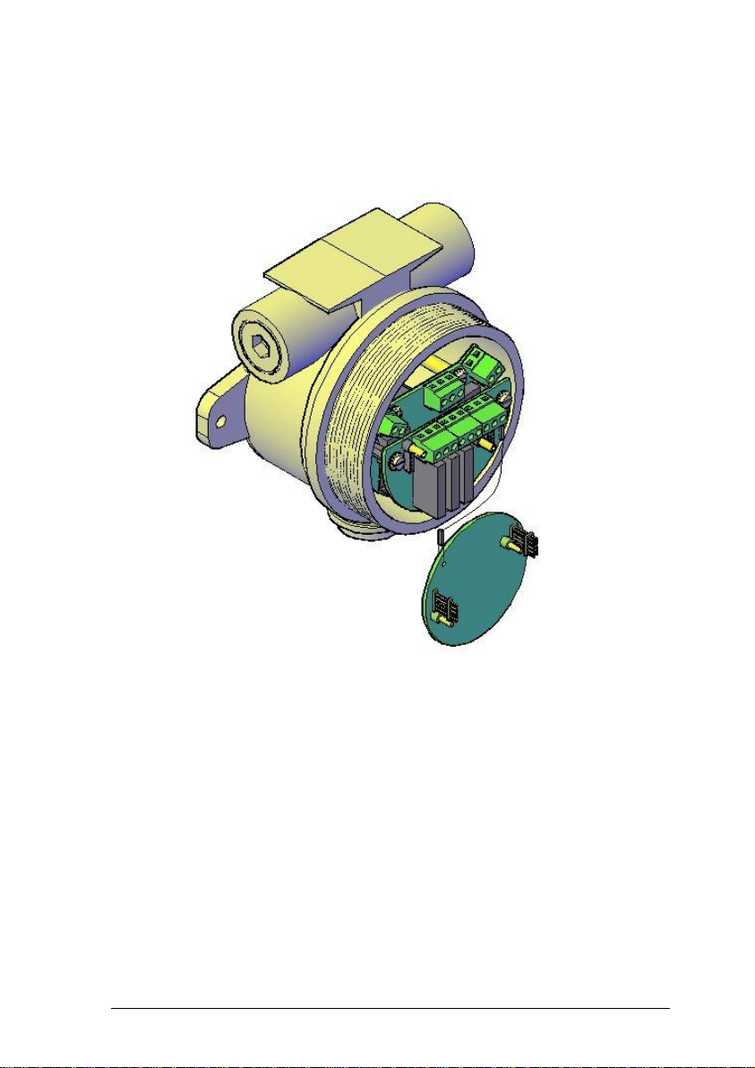
Step 9
Fix datamate cable, the boards removed from the support pillars and finally
the display board back into position.
Page 52
Installation, Commissioning & Routine Gas Testing
FGD10A Oxygen / Toxic Gas Detector
TD18/002
Issue:
19
Change Note:
2033
Page 51
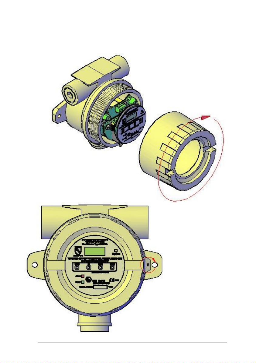
Step 10
Replace cover and fully tighten.
Step 11
Turn the cover securing stud clockwise until secure.
Page 53

Installation, Commissioning & Routine Gas Testing
FGD10A Oxygen / Toxic Gas Detector
TD18/002
Issue:
19
Change Note:
2033
Page 52
9. FUSES
A 1Amp anti-surge fuse, housed within a surface mounted holder, is located
within the FGD10A to prevent overloading of the electronic circuitry in the
event of an internal fault.
In the event of the internal fuse blowing, access can be gained using the
following procedure:
1. Switch OFF the supply to the FGD10A.
2. Release the grub screw located near the lip of the enclosure
cover.
Note:
It is not necessary to remove the grub screw to release the
enclosure front cover.
3. Remove the enclosure front cover by rotating it several times in
an anti-clockwise direction.
4. Unplug the display board from within the enclosure.
5. Remove the 3 screws located around the edge of the next
board.
6. Unplug this board.
7. The surface mounted fuse holder can now be located on the
board below. Replace only with a fuse of the same type and
rating:-
1Amp Antisurge ‘Nanofuse’ (SSCL Code: 160153)
Assembly is the reverse of the above procedure.
Page 54
Installation, Commissioning & Routine Gas Testing
FGD10A Oxygen / Toxic Gas Detector
TD18/002
Issue:
19
Change Note:
2033
Page 53
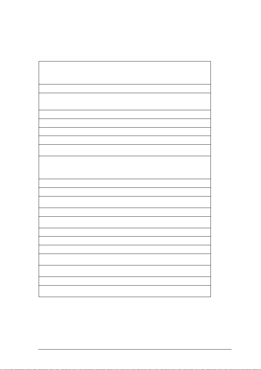
Specification
Materials
:
Instrument Body – Aluminium Pressure Die Casting
Sensor Insert – Stainless Steel Grade 316
Magnetic Pen – Stainless Steel Grade 316
Weather guard – Stainless Steel Grade 304 & Nylon 66
Cable entries
:
2 x 20mm
Weights
:
FGD10A (excluding weather guard) – 1.5Kg
Magnetic Pen – 60 grams
Weather guard – 200 grams
Gas type
:
Oxygen - Toxic
Input voltage
:
12 to 24 volts dc with relays
Input power
:
5 Watts maximum
Internal fuse
:
1 Amp antisurge 'Nanofuse'
Analogue
output
:
4 to 20mA (10 bit resolution)
Relays
Relay 1 – Alarm 1
Relay 2 – Alarm 2
Relay 3 – Fault
Contact Rating 300Vac, 3 Amps (Non-inductive load)
RS232 output
:
Communications with PC at 19200 baud
Sensor type
:
Oxygen or electrochemical toxic
Measurement
range
:
Various, depends upon sensor
Response time
:
depends upon sensor
Measurement
resolution
:
depends upon sensor
IP rating
:
Enclosure IP66, Sensor IP65
Display
:
4 Digit, 7 segment liquid crystal
Keypad
:
4-Button magnetically operated
Software
:
Software configuration provided via LCD display and
multifunction keypad
Operating
temperature
:
- 20 to +60 O C
Humidity range
:
0 to 95% RH non-condensing
Operating
pressure
:
Atmospheric + or - 10%
Page 55
Installation, Commissioning & Routine Gas Testing
FGD10A Oxygen / Toxic Gas Detector
TD18/002
Issue:
19
Change Note:
2033
Page 54
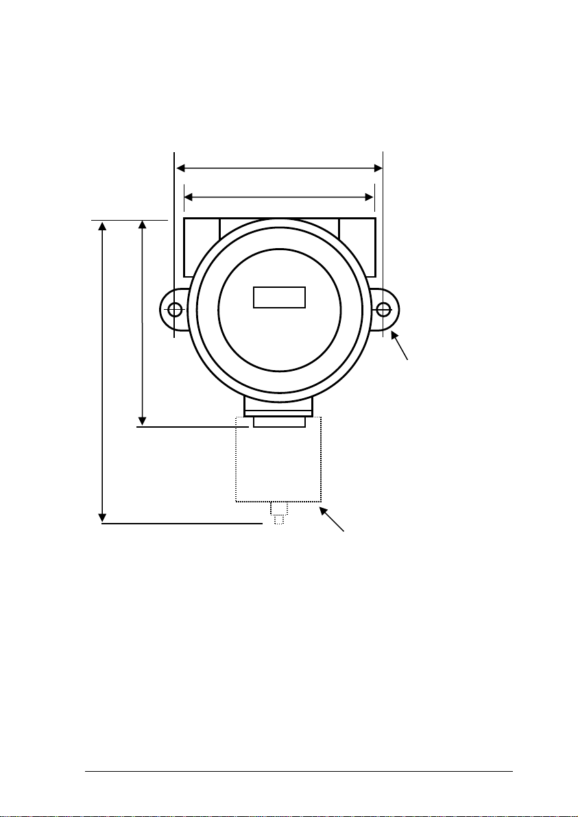
Dimensions
Optional
Weatherguard
115
126 Centres
190
136
2 x 7mm dia.
mounting holes
Maximum Depth = 127mm
Page 56
Installation, Commissioning & Routine Gas Testing
FGD10A Oxygen / Toxic Gas Detector
TD18/002
Issue:
19
Change Note:
2033
Page 55
10. CERTIFICATION
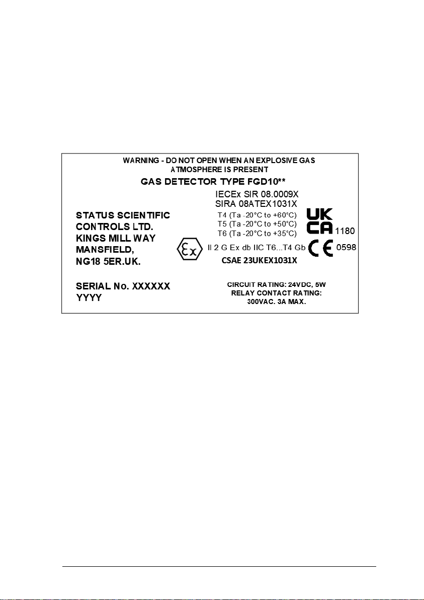
The FGD10 Series of Gas Detectors are ATEX and IECEx certified for use in
potentially explosive atmospheres and is marked as follows:-
** Denotes additional characters that define the gas detector configuration
e.g. Enclosure type and sensor arrangement.
YYYY – Denotes year of manufacture.
Special Conditions of Safe Use
The specific conditions of use are applicable to ATEX, IECEx and UKEX
certificates.
Specific conditions of use
1. The gap between the SI-IR sensor and its housing in the gas detector is
0.11 mm maximum and should not be enlarged during maintenance etc.
2. Only Loctite 243 or a compound equal strength shall be re-applied to the
threads of the type SI-M sensor after replacing the sensing element.
3. The SI-IR sensors shall not be installed or removed when an explosive
gas atmosphere is present.
4. When FGD10 gas detector is provided with a remote GSH4 gas sensor,
the integral conductors shall be suitably clamped within 100 mm of the point
at which they exit the body of the Gas Sensor Type GSH4.
Page 57

Installation, Commissioning & Routine Gas Testing
FGD10A Oxygen / Toxic Gas Detector
TD18/002
Issue:
19
Change Note:
2033
Page 56
5. When gas detector is supplied with a GSH4 sensor for remote connection,
it is the user’s responsibility to ensure that the earth continuity is maintained
via the mounting arrangement.
6. When the equipment is supplied with a remote GSH4 gas sensor, the
individual interconnecting cables shall be no less than 3m in length and the
cables shall be effectively clamped to prevent pulling or twisting.
7. For information on the dimensions of the flameproof joints of the
enclosures, the manufacturer shall be contacted.
8. It is the responsibility of the installation engineer to ensure that suitable Ex
db IIC IECEx / ATEX equipment certified cable glands and blanking elements
are installed in accordance with IEC / EN 60079-14
9. Blanking elements are not designed to be removed.
A copy of the certificate is available for download from:-
www.processsensing.com
Note: Conditions 1 and 3 are not applicable to this product.
Compliance with the Essential Health and Safety Requirements has been
assured by compliance with:
EN 60079-0: 2018 EN 60079-1 : 2014
Electrical data
Power supply - 12Vdc to 24Vdc, 5W
Relay contact rating – 300Vac, 3 Amps
Installation instructions
The cable entry devices and blanking elements of unused apertures shall be
of a certified flameproof type, suitable for the conditions of use and correctly
installed.
With the use of conduit, a suitable certified sealing device such as a stopping
box with compound shall be provided immediately at the entrance to the
flameproof enclosure.
A copy of the certificate is available for download from:-
www.processsensing.com
Page 58

Installation, Commissioning & Routine Gas Testing
FGD10A Oxygen / Toxic Gas Detector
TD18/002
Issue:
19
Change Note:
2033
Page 57
CUSTOMER NOTES
Page 59

Installation, Commissioning & Routine Gas Testing
FGD10A Oxygen / Toxic Gas Detector
TD18/002
Issue:
19
Change Note:
2033
Page 58
CUSTOMER NOTES
Page 60

Installation, Commissioning & Routine Gas Testing
FGD10A Oxygen / Toxic Gas Detector
TD18/002
Issue:
19
Change Note:
2033
Page 59
CUSTOMER NOTES
 Loading...