

Page 1
MADE
IN U.S.A.
1 YEAR
WARRANTY
Page 2
Page 3
BEFORE OPERATING THE FDT-81
Important Notice!
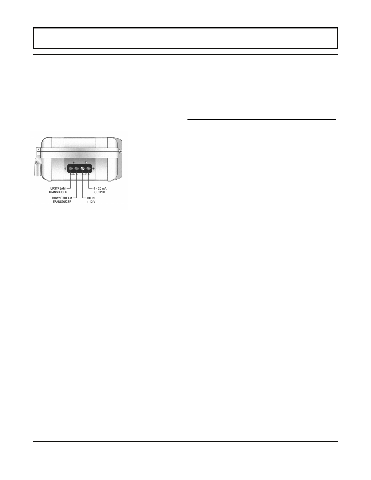
Figure 1.1
The FDT-81 flow meter is equipped with a Lead Acid Gel Cell
battery. This battery will require charging before initial
operation.
Apply power, utilizing the enclosed 12 Volt DC output line
power converter or cigarette-style power cord, to the FDT-81
for a period of 16-24 hours prior to using the product for the
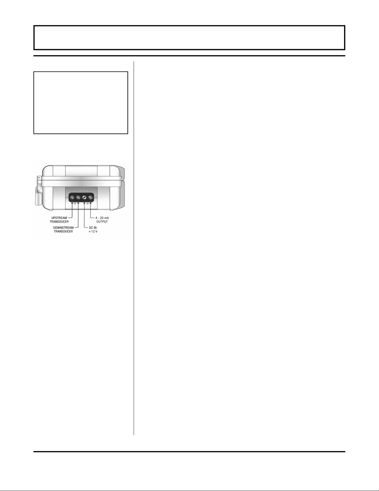
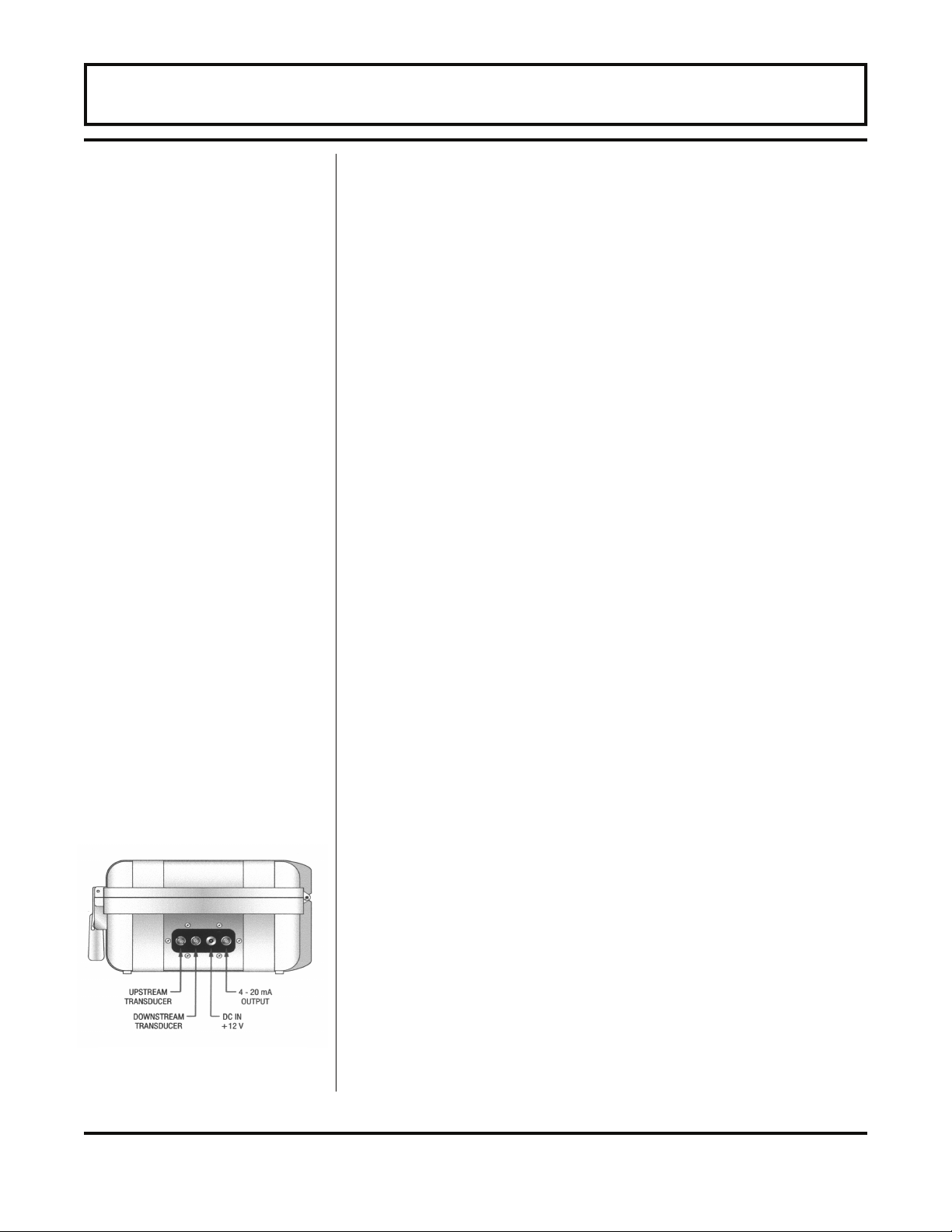
first time. The power converter connects to the DC IN +12V
socket connection located on the side of the enclosure. See
Figure 1.1. A fully charged battery will provide up to 24
hours of continuous operation before recharging will be
necessary.
When the battery level has decreased to a point where
recharging is required, the LOW BATTERY indicator will
illuminate on the front panel. At that point, the meter will only
operate a short time more until it automatically turns itself
off—preventing excessive battery discharge that can damage
the Gel Cell battery. The FDT-81 has an integral charging
circuit that prevents overcharging. The instrument can be
permanently connected to AC line power without damaging
the flow meter or the battery. Page 1.10 of this manual
contains additional recommendations to preserve and
maximize the power in the FDT-81 battery.
If the FDT-81 is to be used for extended periods of operation,
the AC power converter or the 12 volt cigarette converter can
remain connected indefinitely.
- 1.3 - FDT-81
Page 4

TABLE OF CONTENTS
Part 1 -
Introduction
Connections
Inputs and
Outputs
Quick-Start Operating Instructions 1.6
Introduction
General 1.8
Applications 1.8
Product Identification 1.9
Product Specifications 1.10
Transmitter Connections 1.11
Battery Charging and Maintenance 1.12
Input/Output Connections and Options
4-20 mA Output 1.15
Optional ISO-Mods 1.16
Pages
Part 2 -
Transducer
Installation
Transducer Mounting Location 2.1
Transducer Spacing
Mounting Modes 2.4
Keypad Entry 2.5
Transducer Mounting
Pipe Preparation 2.14
V-Mount and W-Mount Installation 2.15
Z-Mount Installation 2.16
Mounting Track Installation 2.19
Small Pipe Transducer Installation 2.20
- 1.4 - FDT-81
Page 5

TABLE OF CONTENTS
Part 3 Operation
Instrument Startup and Configuration 3.1
Keypad Operation 3.2
Menu Structure
BASIC MENU 3.4
OUT2 MENU 4-20 mA 3.13
Optional Input/Output 3.15
SENSOR MENU 3.19
SECURITY MENU 3.19
SERVICE MENU 3.20
Signal Strength 3.21
Setting ZERO Flow 3.23
DISPLAY MENU 3.24
Pages
Appendix
Appendix
Error Codes
Fluid Characteristic Table
Digital Communications Protocol
Pipe Dimension Chart: Cast Iron
Pipe Dimension Chart: Ductile Iron
Pipe Dimension Chart: ST, SS, PVC
Velocity to Volumetric Conversion
Addendum - Heat Flow
Statement of Warranty
- 1.5 - FDT-81
Page 6
QUICK-START OPERATING INSTRUCTIONS
Transducer
Location
This manual contains detailed operating instructions for all
aspects of the FDT-81 instrument. The following condensed
instructions are provided to assist the operator in getting the
instrument configured and measuring as quickly as possible.
This pertains to basic operation only. If specific instrument
features are to be used or if the installer is unfamiliar with this
type of instrument, refer to the appropriate section in the
manual for complete details.
1. TRANSDUCER LOCATION
A. In general, select a mounting location on the piping
system with a minimum of 10 pipe diameters (10 times
the pipe inside diameter) of straight pipe upstream and
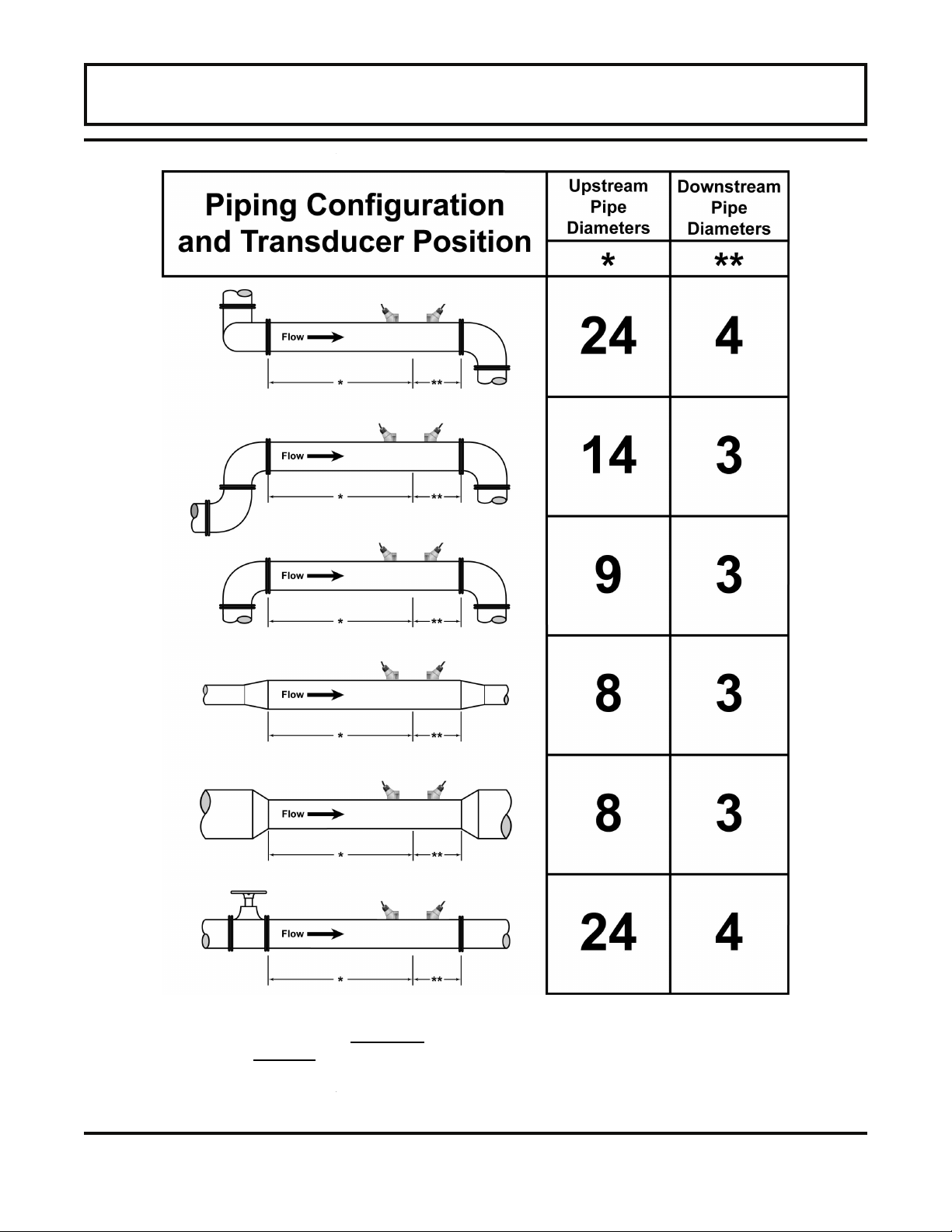
5 straight diameters downsteam. See Table 2.1 for
detailed piping configurations and recommended
lengths of straight pipe.
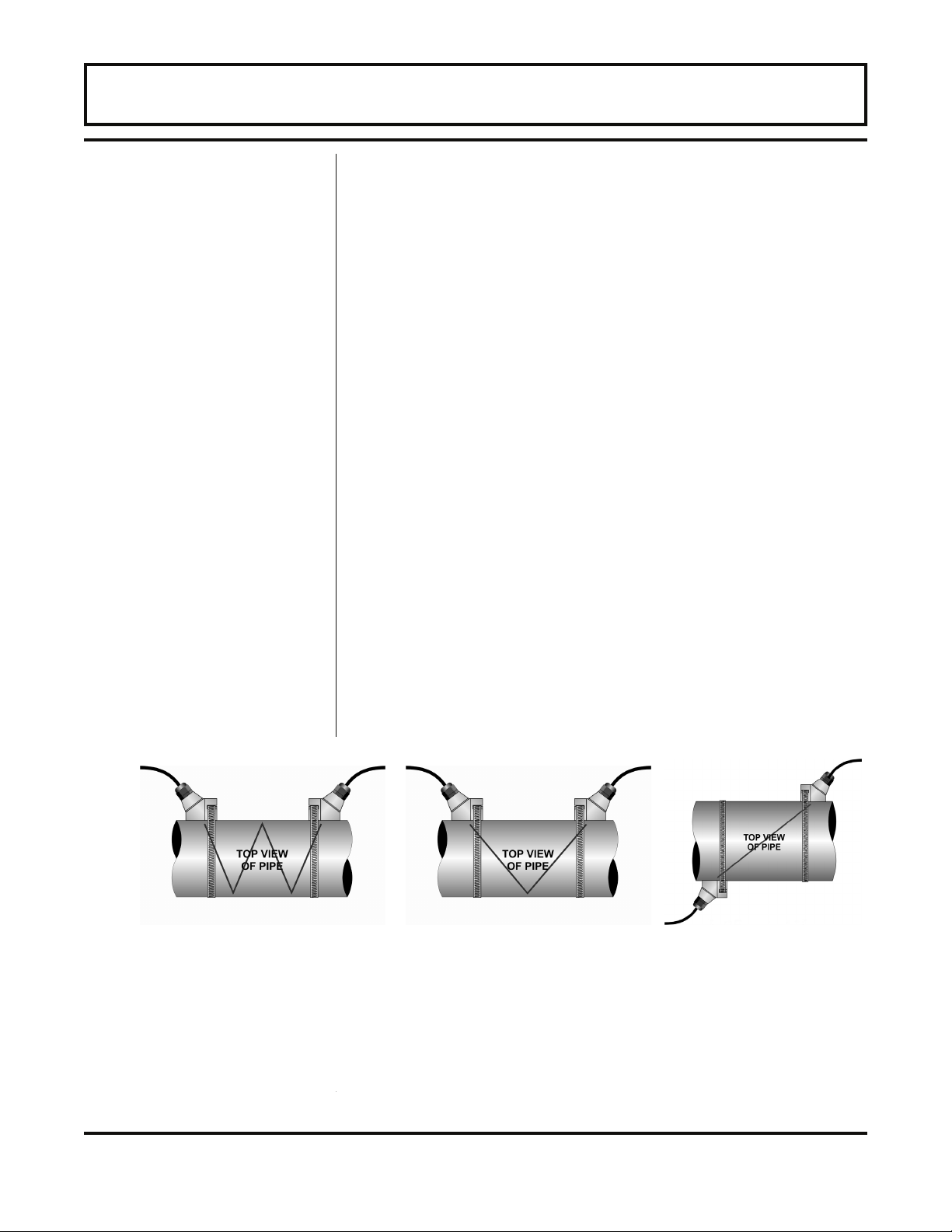
B. Select a mounting method for the transducers based
on pipe size and liquid characteristics. See Figure
1.2. Select W-Mount for plastic pipes flowing clean,
non-aerated liquids in the 2-3 inch [50-75 mm] internal
diameter range. Select V-Mount for pipes of all
materials and most liquids in pipe sizes from 2-10
inches [50-250 mm]. Select Z-Mount for pipes 10-100
inches [250-2540 mm] inches.
W-Mount V-Mount Z-Mount
Figure 1.2
- 1.6 - FDT-81
Page 7
QUICK-START OPERATING INSTRUCTIONS
*Nominal values for these
parameters are included
within the FDT-81 operating
system. The nominal values
may be used as they appear
or may be modified if exact
system values are known.
C. Enter the following data into the FDT-81 transmitter via
the integral keypad.
1. Transducer mounting method
2. Pipe O.D. (Outside Diameter)
3. Pipe wall thickness
4. Pipe material
5. Pipe sound speed*
6. Pipe relative roughness*
7. Pipe liner thickness
8. Pipe liner material (if present)
(if present)
9. Fluid type
10. Fluid sound speed*
11. Fluid viscosity*
12. Fluid specific gravity*
D. Record the value calculated and displayed as Transducer
Spacing/XDCR SPC.
2. PIPE PREPARATION AND TRANSDUCER MOUNTING
A. The piping surface, where the transducers are to be
mounted, needs to be clean and dry. Remove loose
scale, rust and paint to ensure satisfactory acoustical
bonds.
Figure 1.3
Connections
Startup
B. Apply a liberal amount of couplant grease onto the
transducer faces.
C. Attach the transducers to the pipe at the location(s)
determined in Step 1. Refer to Figure 1.2 for proper
orientation.
3. TRANSDUCER/POWER CONNECTIONS
A. If additional transducer cable is required, utilize RG59
coaxial wire with 75 Ohm terminations.
B. Refer to the WIRING DIAGRAM located on the inner
door of the FDT-81 transmitter and Figure 1.3 for
proper power and transducer connections.
4. INITIAL SETTINGS AND POWER UP
A. Press the ON button on the flow meter keypad.
B. From the Service Menu, verify that signal strength is
greater than 2.0%.
C. Input proper units of measure and I/O data.
- 1.7 - FDT-81
Page 8
PART 1 - INTRODUCTION
General
Application
Versatility
The FDT-81 ultrasonic flow meter is designed to measure the
fluid velocity of liquid within closed conduit (pipe). The
transducers are a non-contacting, clamp-on type, which will
provide benefits of non-fouling operation and ease of
installation.
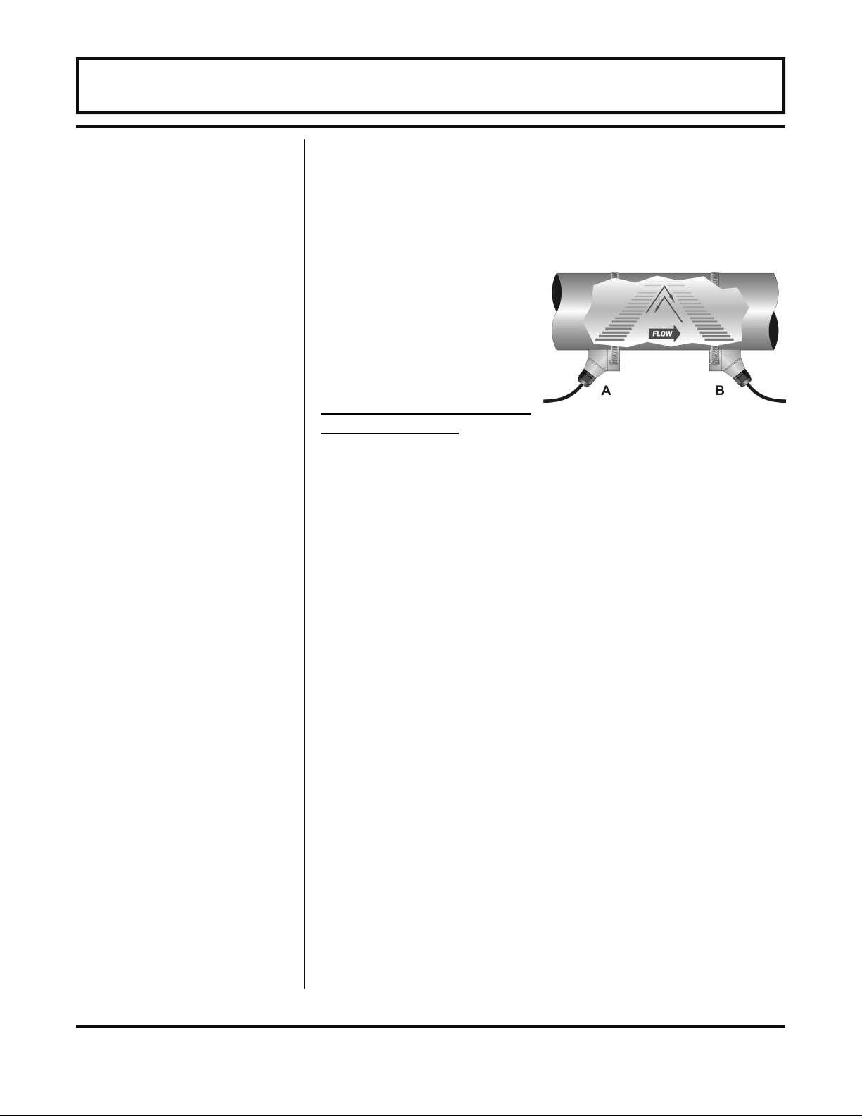
FDT-81 transit time flow
meters utilize two
transducers that function as
both ultrasonic transmitters
and receivers. The
transducers are clamped on
the outside of a closed pipe
at a specific distance from
each other. The
transducers can be mounted in V-mode where the sound
transverses the pipe two times, W-mode where the sound
transverses the pipe four times, or in Z-mode where the
transducers are mounted on opposite sides of the pipe and
the sound crosses the pipe once. This selection is based on
pipe and liquid characteristics. The flowmeter operates by
alternately transmitting and receiving a frequency modulated
burst of sound energy between the two transducers and
measuring the time interval that it takes for sound to travel
between the two transducers. The difference in the time
interval measured is directly related to the velocity of the
liquid in the pipe.
The FDT-81 flow meter can be successfully applied on a
wide range of metering applications. The simple to program
transmitter allows the standard product to be used on pipe
sizes ranging from 2 - 100 inch [50 - 2540 mm] internal
diameters. A variety of liquid applications can be
accommodated: ultrapure liquids, potable water, chemicals,
raw sewage, reclaimed water, cooling water, river water,
plant effluent, etc. Because the transducers are noncontacting and have no moving parts, the flow meter is not
affected by system pressure, fouling or wear. Standard
transducers are rated to 300 °F [150 °C]. Higher temperatures
can be accommodated. Please consult the factory for
assistance.
- 1.8 - FDT-81
Page 9

PART 1 - INTRODUCTION
User Safety
Data Integrity
Product
Identification
The FDT-81 employs modular construction and provides
electrical safety for the operator. The display face contains
voltages no greater than 10 Vdc. All user connections are
made through sealed bulk-head plugs located on the side of
the FDT-81 enclosure.
Non-volatile flash memory retains all user-entered
configuration values in memory for several years, even if
power is lost or the unit is turned off. Password protection is
provided as part of the Security menu and prevents
inadvertent configuration changes or totalizer resets.
The serial number and complete model number of the FDT-81
is located on the inside of the transmitter’s front cover.
Should technical assistance be required, please provide the
Omega Customer Service Department with this information.
- 1.9 - FDT-81
Page 10
PART 1 - SPECIFICATIONS
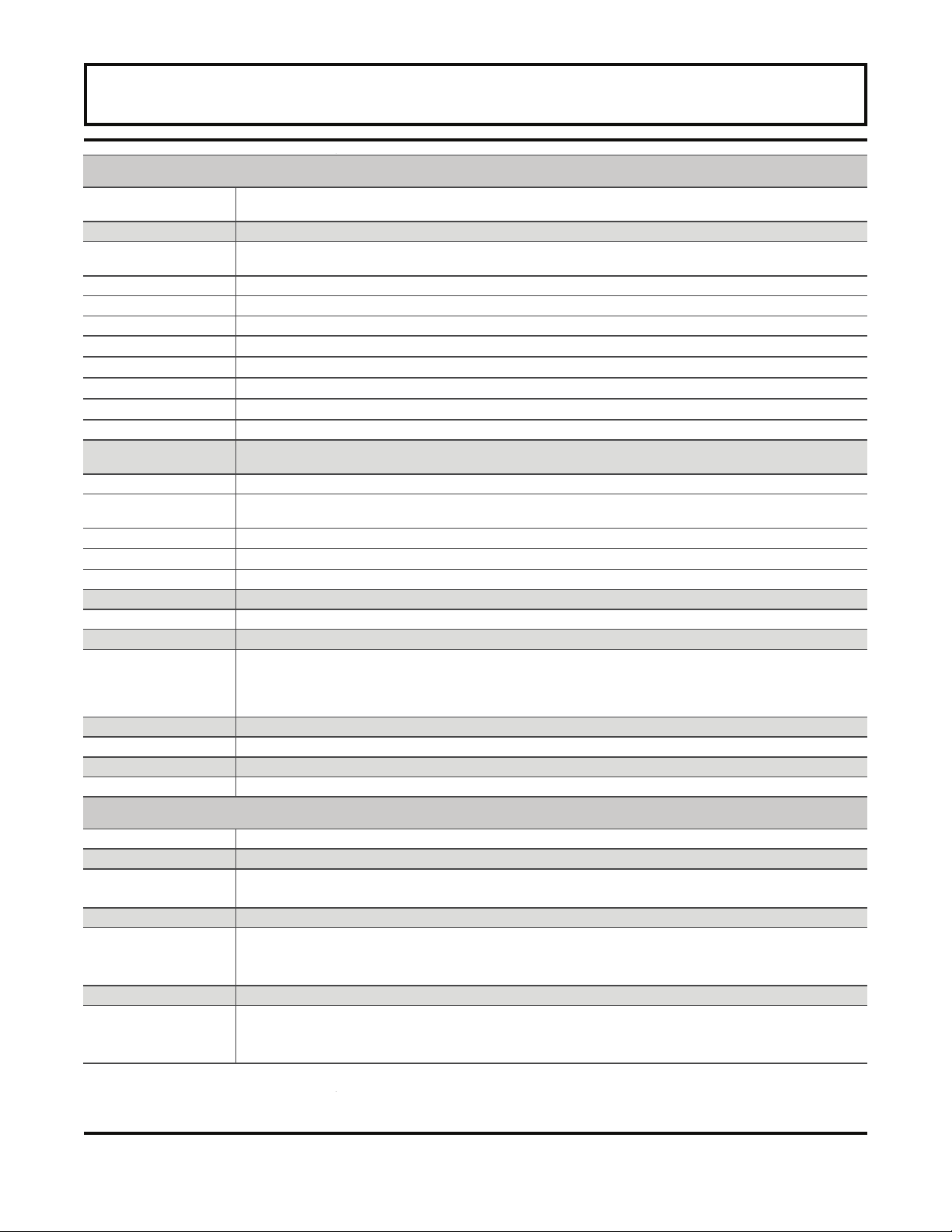
TRANSMITTER
Power Requirements
Velocity Range
Inputs/Outputs
Standard
4-20 mA 800 Ohm max; 12-bit resolution, passive or active
Options
Rate Pulse MOSFET, 0.21 Ohms, 100 V max, 0 to 2,500 Hz max
Dual Relay 2 separate Form C relays, 200 VAC max at 0.5 A (resistive)
RS232C Data rate to 57.6k
RS485 Supports up to 119 drops
Heat Flow (RTD) Supports two 1000 Ohm RTDs, multiplexed, 12-bit resolution
Display
Units User configured
Rate Gal, liters, million gal, ft³, m³, acre-ft, oil barrels (42 gal), liquid barrels (31.5 gal), ft, m, lb, kg, BTU, MBTU,
Time Seconds, minutes, hours, days
Totalizer
Mode Forward, reverse, net, batch
Ambient Conditions
Enclosure NEMA 4X (IP-66) while open, NEMA 6 (IP-68) while closed, ABS with SS hardware
Size 14.00" H × 6.06" W × 10.56" D (355.6 mm H × 153.9 mm W × 268.2 mm D); 14.8 lbs (6.7 Kg)
Flow Rate Accuracy FDT-81-STD / FDT-81-HT: ±1% of reading at rates >1 FPS (0.3 MPS), ±0.01 FPS (±0.003 MPS) at rates lower
Flow Sensitivity 0.001 FPS (0.0003 MPS)
Repeatability ±0.01% of reading
Response Time (Flow) 0.3 to 30 seconds, user configured, to 100% of value, step change in flow
Security Keypad lockout, user selected 4 digit access code
Internal 12 V lead-acid Gel Cell battery provides 24 hrs of continuous operation @ 20 °C. Charging: Wall mount
power converter. 115 or 230 VAC 50/60 Hz ±15% VA max; 12-15 VDC @ 2.5 VA max
-40
to
+40
All output modules are optically isolated from earth and system grounds.
One module and one data logger may be installed.
128 × 64 pixel graphics LCD, LED backlit. Two user selectable font sizes 0.35" (8.9 mm) or 0.2" (5 mm)
8 digit rate, 8 digit totalizer (resettable)
MMBTU, ton
Gal, liters, million gal, ft³, m³, acre-ft, oil barrels (42 gal), liquid barrels (31.5 gal), lb, kg, BTU, MBTU, MMBTU, ton
-40
°F to +185 °F
than 1 FPS
FDT-81-SML: 1" and larger units ±1% of reading from 10-100% of measuring range, ±0.01 FPS (±0.003 MPS) at
rates lower than 10% of measuring range; ½" and ¾" units ±1% FS
FPS (-12 to +12 MPS)
(-40
°C to
+85
°C), 0 to 95% relative humidity (non-condensing)
TRANSDUCERS
Liquid Types Most non-aerated, clean liquids
Cable Length Up to 990 ft (300 meters); standard lengths 20, 50, 100 ft (6, 15, 30 meters)
Pipe Sizes FDT-81-STD / FDT-81-HT: 2 inch and larger
FDT-81-SML: 1/2", 3/4", 1", 1-1/4", 1-1/2", 2" (ANSI pipe, copper tube, tubing)
Environment NEMA 6
Pipe Surface
Temperature
Ambient Conditions
Housing Material FDT-81-STD: CPVC, Ultem
FDT-81-STD:
FDT-81-SML:
FDT-81-HT:
-40
°F to +185 °F
FDT-81-SML: PVC, Ultem
FDT-81-HT: PTFE, Vespel
-40
°F to +250 °F
-40
°F to +185 °F
-40
°F to +350 °F
(-40
°C to
(-40
°C to +121 °C)
(-40
°C to
+85
(-40
°C to +177 °C)
+85
°C)
®
, and nylon
®
, and nylon
®
, and nickel-plated brass
°C)
- 1.10 - FDT-81
Page 11

PART 1 - FDT-81 TRANSMITTER CONNECTIONS
Transmitter
Location
Considerations
After unpacking, it is recommended to save the shipping
carton and packing materials in case the instrument is stored
or re-shipped. Inspect the equipment and carton for damage.
If there is evidence of shipping damage, notify the carrier
immediately.
When the FDT-81 is to be utilized for extended periods of
time in one location, the enclosure should be placed in an
area that is convenient for servicing, calibration or for
observation of the LCD readout.
1. Locate the transmitter within the length of transducer
cable that was supplied with the FDT-81 system. If this is
not possible, additional cable should be RG59 coaxial
cable and terminations should be 75 Ohm. Longer cables
are also available by contacting the factory.
2. Place the FDT-81 transmitter in a location that is:
♦ Where little vibration exists.
♦ Protected from falling corrosive fluids.
♦ Within ambient temperature limits -40 to +185 °F [-40 to
+85 °C]
♦ Out of direct sunlight. Direct sunlight may increase
transmitter temperatures above maximum limit.
3. If the transmitter will be subjected to a wet environment, it
is recommended that the cover remain closed and the
latches secured after configuration is completed. The
faceplate/keypad of the FDT-81 is watertight, but avoid
letting water collect on the keypad area.
It is highly recommended that the internal battery in the FDT-81
be fully charged before using the meter for the first time.
Details covering this procedure are located on Page 1.1 of
this manual.
- 1.11 - FDT-81
Page 12
PART 1 - FDT-81 TRANSMITTER CONNECTIONS
Electrical
Connections
Figure 1.4
Battery Charging
and External Power
Sources
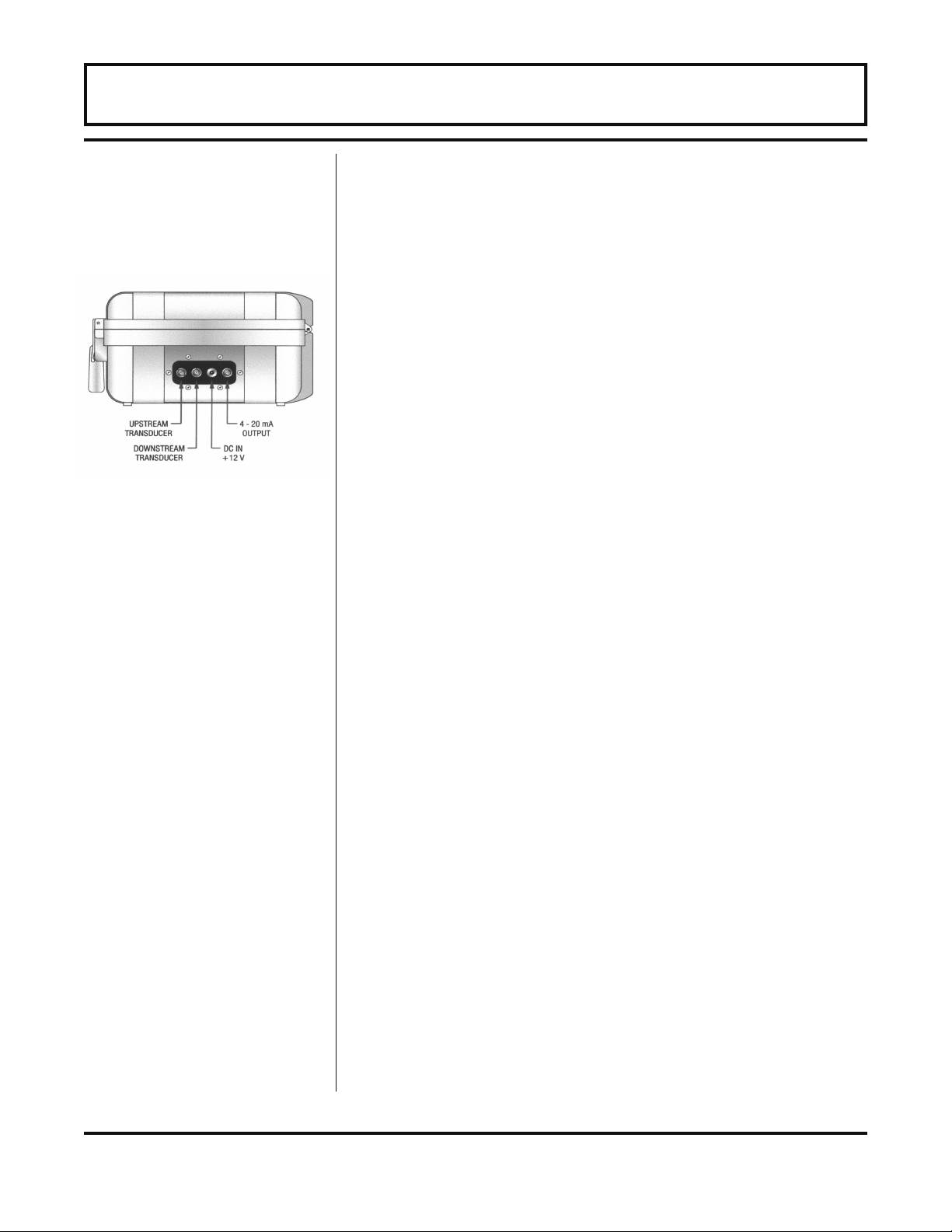
1. The connectors located on the side of the FDT-81 consist
of three 1/4 turn BNC-type and one 5.5mm power plug.
These connectors are environmentally sealed, but it is
recommended not to allow water or other liquids to collect
in the electrical connections pocket.
2. Connect the appropriate wires to the corresponding
connections on the transmitter. The transducer cable has
markings of UPSTREAM and DOWNSTREAM to assist in
the installation process. The UPSTREAM transducer is
the one located closer to the direction from which fluid
flow normally comes from (The fluid normally passes the
UPSTREAM transducer before passing the
DOWNSTREAM transducer.) If the transducer wires are
connected backwards, a negative flow indication will be
observed on the flow meter display. See Figure 1.4 or
the Wiring Diagram located on the inner door of the
transmitter.
NOTE: The transducer cables carry low level signals. If
additional cable is required, it must be RG59 coaxial cable
with 75 Ohm terminations. Longer cables are also available
from the factory.
The 12 volt DC power converter and 12 volt cigarette-style
power cord connect to the socket connection located on the
side of the enclosure. See Figure 1.4. A fully charged
battery will provide up to 24 hours of continuous operation
before recharging will be necessary. When the battery level
has decreased to a point where recharging is required, the
LOW BATTERY indicator will illuminate on the front panel. At
that point, the meter will only operate a short time more until
it automatically turns itself off—preventing excessive battery
discharge that can damage the Gel Cell battery.
- 1.12 - FDT-81
Page 13

PART 1 - FDT-81 TRANSMITTER CONNECTIONS
If the FDT-81 is to be used for extended periods of operation,
the 12 Vdc line power converter or the 12 V cigarette-style
converter can remain connected indefinitely.
To charge the internal Gel Cell battery, apply power, utilizing
the enclosed 12 Vdc line power converter or cigarette-style
power cord, to the FDT-81 for a period of 16-24 hours. The
FDT-81 has an integral charging circuit that prevents
overcharging. The instrument can be permanently connected
to AC line power without damaging the flow meter or the
battery.
The Gel Cell battery is “maintenance free”, but it still requires
a certain amount of attention to prolong its useful life. To
obtain the greatest capacity and longevity from the battery,
the following practices are recommended:
• Do not allow the battery to completely discharge.
(Discharging the battery to the point where the LOW
BATTERY indicator illuminates will not damage the
battery. Allowing the battery to remain discharged for
long periods of time can degrade the storage capacity of
the battery.) When not in use, continually charge the
battery by keeping the 12 Vdc line power converter
plugged in and connected to the flow meter. The FDT-81
battery management circuitry will not allow the battery to
become “over-charged”.
NOTE: The FDT-81 will automatically enter a low power
consumption mode approximately 1-1/2 minutes after the
LOW BATTERY indicator illuminates. This circuit prevents
excessive discharge of the internal battery.
• If the FDT-81 is stored for prolonged periods of time,
monthly charging is recommended.
• If the FDT-81 is stored for prolonged periods of time, store
at a temperature below 70 °F [21 °C].
Use wiring practices that conform to local codes (National
Electric Code Handbook in the USA). Use only the power
converters that have been supplied with the FDT-81 flow
meter. The ground terminal, if present on the converter, is
mandatory for safe operation.
- 1.13 - FDT-81
Page 14

PART 1 - FDT-81 TRANSMITTER CONNECTIONS
CAUTION: Any other wiring method may be unsafe or cause
improper operation of the instrument.
It is recommended not to run line power with other signal
wires within the same wiring tray or conduit.
NOTE: This instrument requires clean electrical line power.
Do not operate this unit on circuits with noisy components
(i.e. Fluorescent lights, relays, compressors, variable
frequency drives, etc.).
The FDT-81 can be operated from a 11-15 Vdc source, using
the included auto-style power cord, as long as it is capable of
supplying at least 3 Watts—observe proper polarity.
- 1.14 - FDT-81
Page 15
PART 1 - FDT-81 TRANSMITTER CONNECTIONS
General
Information
Regarding Input/
Output: ISO-MODs
Standard
4-20 mA Output
The FDT-81 flow meter may contain two Isolated Input/output
Modules (ISO-MODs); one located inside of the flow meter
enclosure and one that is user accessible, located under the
access door on the keyboard. The standard configuration of
these modules is to have the internal module configured as
an actively powered 4-20 mA.
ISO-MODs are epoxy encapsulated electronic input/output
modules that are simple to install and replace in the field. All
modules are 2,500 volt optically isolated from FDT-81 power
and earth grounds -- eliminating the potential for ground
loops and reducing the chance of severe damage in the
event of an electrical surge.
The standard 4-20mA output may be replaced with one of the
following four ISO-MODs: dual-relay, rate pulse, RS232C,
and RS485. FDT-81 supports one ISO-MOD input/output
module. All modules are field configurable by utilizing the
keyboard. Field wiring connections to ISO-MODs are quick
and easy using pluggable terminals.
The 4-20 mA Output Module interfaces with virtually all
recording and logging systems by transmitting an analog
current signal that is proportional to system flow rate.
Independent 4 mA and 20 mA span settings are established
in software using the FL 4MA and FL 20MA settings in the
OUTPUT2 configuration menu. These entries can be set
anywhere in the -40 to +40 fps [-12 to +12 mps] measuring
range of the instrument. Output resolution of the module is
12-bits (4,096 discrete points). The module can drive more
than 800 ohms of load with its internally generated 24 volt
power source.
A 4-20 mA output interface cable has been included with the
FDT-81 package. Connect the 1/4-turn BNC connection to
the jack located on the side of the flow meter. See Figure
1.5. The red clip on the cable provides the positive leg of the
output and the black clip provides the negative side. Verify
that the sum of the resistances in the loop do not exceed 800
Ohms. The FDT-81 output is configured to source current.
Refer to Section 3 of this manual for detailed information
Figure 1.5
- 1.15 - FDT-81
regarding the configuration, calibration and testing of the 4-20
mA output.
Page 16

PART 1 - FDT-81 TRANSMITTER CONNECTIONS
Other Optional
ISO-Mods
There are four additional optional ISO-Mods available in
replacement of the standard 4-20mA output. If interested in
one of these optional ISO-Mods, please contact Omega.
- 1.16 - FDT-81
Page 17

PART 2 - TRANSDUCER POSITIONING
General
The transducers that are utilized by the Series FDT-81
contain piezoelectric crystals for transmitting and receiving
ultrasound signals through walls of liquid piping systems.
The transducers are relatively simple and straight-forward to
install, but spacing and alignment of the transducers is critical
to the system's accuracy and performance. Extra care
should be taken to ensure that these instructions are carefully
executed.
Mounting of the clamp-on ultrasonic transit time transducers
is comprised of three steps:
1. Selection of the optimum location on a piping system.
2. Entering the pipe and liquid parameters by keying the
parameters into the FDT-81 keypad. The software
embedded in the FDT-81 will calculate proper transducer
spacing based on these entries.
3. Pipe preparation and transducer mounting.
1. Mounting Location
The first step in the installation process is the selection of an
optimum location for the flow measurement to be made. For
this to be done effectively, a basic knowledge of the piping
system and its plumbing are required.
An optimum location would be defined as a piping system
that is completely full of liquid when measurements are being
taken and has lengths of straight pipe such as those
described in Table 2.1. The optimum straight pipe diameter
recommendations apply to pipes in both horizontal and
vertical orientation.
- 2.1 - FDT-81
Page 18
PART 2 - TRANSDUCER POSITIONING
1
Table 2.1
The FDT-81 system will provide repeatable measurements on piping systems that do not meet these
requirements, but the accuracy of these readings may be influenced to various degrees.
1
- 2.2 - FDT-81
Page 19

PART 2 - TRANSDUCER POSITIONING
2. Transducer Spacing
FDT-81 transit time flow meters utilize two transducers that
function as both ultrasonic transmitters and receivers. The
transducers are clamped on the outside of a closed pipe at a
specific distance from each other. The transducers can be
mounted in V-mode where the sound transverses the pipe
two times, W-mode where the sound transverses the pipe
four times, or in Z-mode where the transducers are mounted
on opposite sides of the pipe and the sound crosses the pipe
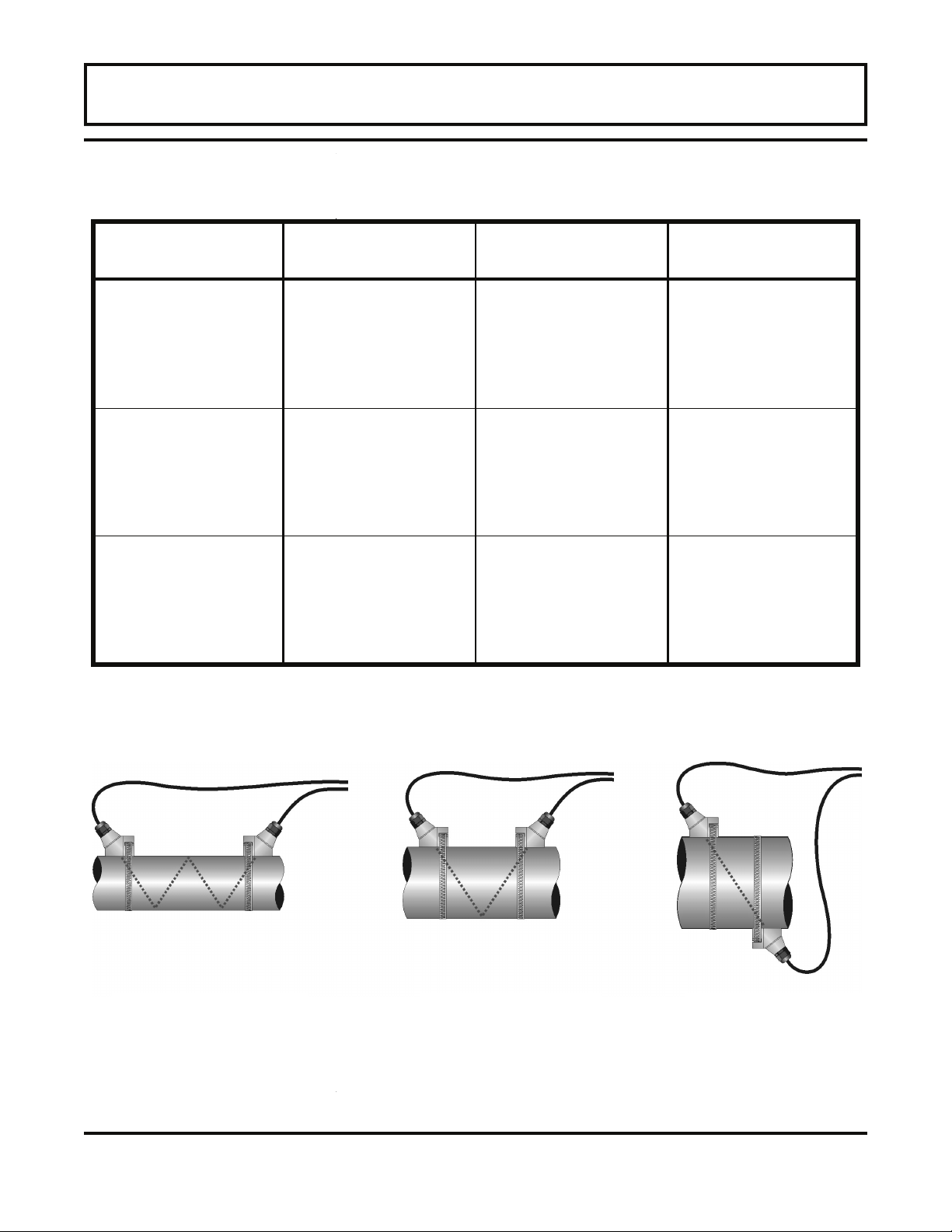
once. For further details, reference pictures located under
Table 2.2. The appropriate mounting configuration is based
on pipe and liquid characteristics. Selection of the proper
transducer mounting method is not entirely predictable and
many times is an iterative process. Table 2.2 contains
recommended mounting configurations for common
applications. These recommended configurations may need
to be modified for specific applications if such things as
aeration, suspended solids or poor piping conditions are
present. W-mode provides the longest sound path length
between the transducers—but the weakest signal strength.
Z-mode provides the strongest signal strength—but has the
shortest sound path length. On pipes smaller than 3 inches
[75 mm], it is desirable to have a longer sound path length,
so that the differential time can be measured more
accurately. Use of the FDT-81 diagnostics in determining the
optimum transducer mounting is covered later in this section.
IMPORTANT: Since the time interval being measured is
influenced by the transducer spacing, it is critical that the
transducer spacing be measured on the pipe accurately to
assure optimum performance from the FDT-81 system.
- 2.3 - FDT-81
Page 20
PART 2 - TRANSDUCER POSITIONING
Table 2.2
Transducer Mounting Modes
Transducer Mount
Mode
W-Mode
V-Mode
Z-Mode
Pipe Material Pipe Size Liquid Composition
Plastic (all types)
Carbon Steel
Stainless Steel
Copper
Ductile Iron
Cast Iron
Plastic (all types)
Carbon Steel
Stainless Steel
Copper
Ductile Iron
Cast Iron
Plastic (all types)
Carbon Steel
Stainless Steel
Copper
Ductile Iron
Cast Iron
1-6 in. (25-150 mm)
1-4 in. (25-100 mm)
1-6 in. (25-150 mm)
1-6 in. (25-150 mm)
Not recommended
Not recommended
6-30 in. (150-750 mm)
4-24 in. (100-600 mm)
6-30 in. (150-750 mm)
6-30 in. (150-750 mm)
3-12 in. (75-300 mm)
3-12 in. (75-300 mm)
> 30 in. (> 750 mm)
> 24 in. (> 600 mm)
> 30 in. (> 750 mm)
> 30 in. (> 750 mm)
> 12 in. (> 300 mm)
> 12 in. (> 300 mm)
Low TSS; non-aerated
Low TSS; non-aerated
Low TSS; non-aerated
Low TSS; non-aerated
Low TSS; non-aerated
Low TSS; non-aerated
Low TSS; non-aerated
Low TSS; non-aerated
Low TSS; non-aerated
Low TSS; non-aerated
Low TSS; non-aerated
Low TSS; non-aerated
Low TSS; non-aerated
Low TSS; non-aerated
Low TSS; non-aerated
Low TSS; non-aerated
TSS = Total Suspended Solids
Transducer Mounting Modes
W-Mount
Configuration
- 2.4 - FDT-81
V-Mount
Configuration
Z-Mount
Configuration
Page 21

PART 2 - TRANSDUCER POSITIONING
Entering the Pipe
and Liquid Data
The FDT-81 system calculates proper transducer spacing by
utilizing piping and liquid information entered by the user.
This information can be entered via the keypad.
In addition, the following information is required before
mounting the transducers on the pipe. Note that much of the
data relating to material sound speed, viscosity and specific
gravity are preprogrammed into the meter. This data only
needs to be modified if it is known that a particular liquid data
varies from the reference value.
1. Transducer mounting configuration (Table 2.2)
2. Pipe O.D. (Outside Diameter)
3. Pipe wall thickness
4. Pipe material
5. Pipe sound speed1
6. Pipe relative roughness1
7. Pipe liner thickness (if present)
8. Pipe liner material (if present)
9. Fluid type
10. Fluid sound speed1
11. Fluid viscosity1
12. Fluid specific gravity1
1
Nominal values for these parameters are included within the
FDT-81 operating system. The nominal values may be used
as they appear or may be modified if exact system values are
known.
After entering the data listed above, the FDT-81 will calculate
proper transducer spacing for the particular data set. This
distance will be in inches if the FDT-81 is configured in
English units, or millimeters if configured in metric units.
- 2.5 - FDT-81
Page 22
PART 2 - TRANSDUCER POSITIONING
Keypad Entry
Graphics Display
Configuration
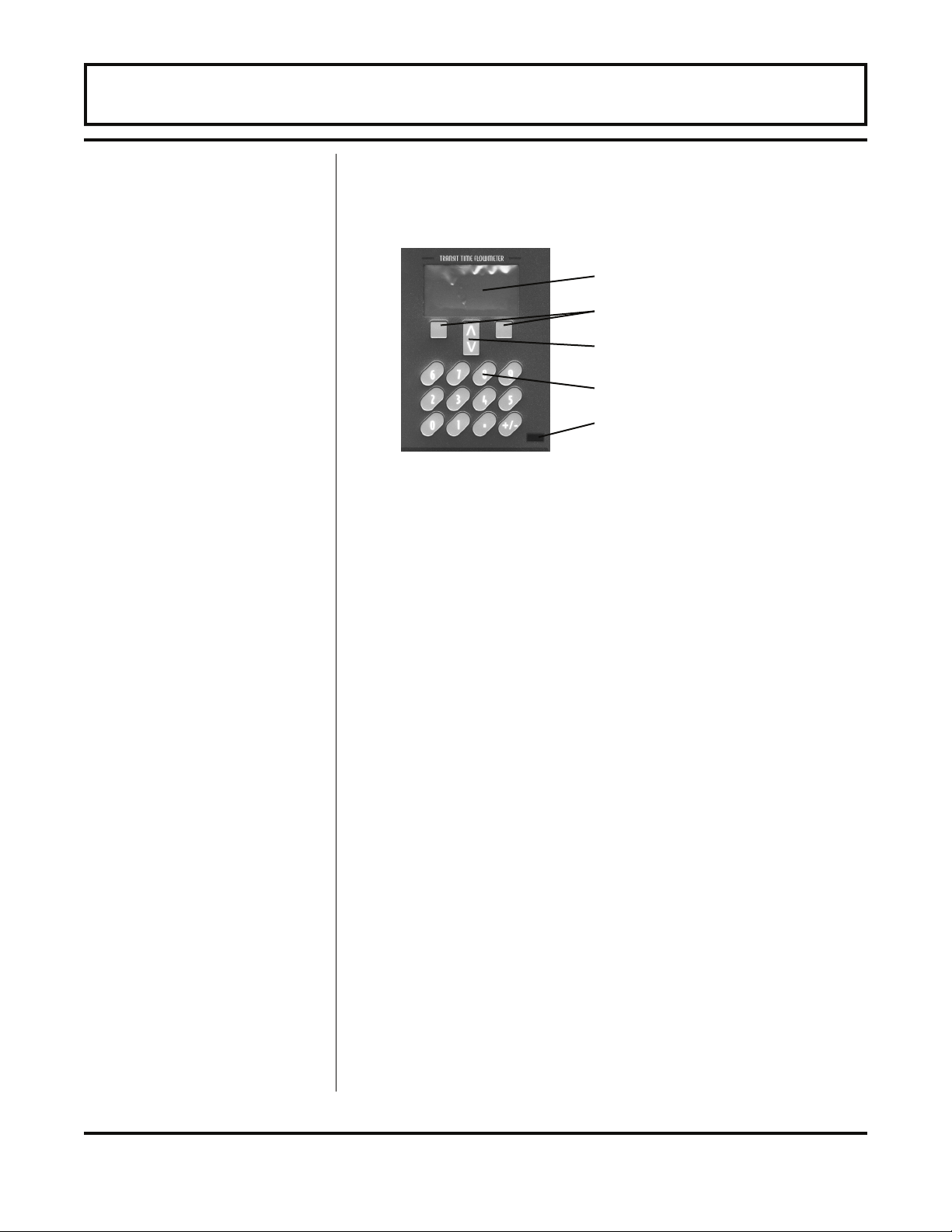
The FDT-81 contains a tactile feedback keypad interface that
allows the user to configure parameters used by the FDT-81
operating system.
Graphics Display
Soft Keys
The FDT-81 system can be configured using
UltraLink™ and a laptop computer. Please refer to
page 2.13 for details regarding data entry in
™
UltraLink
.
Arrow Keys
Numeric Keys
Infrared Communications Port
The following “Soft Key” menu items will be displayed
immediately above the two keys located in the lower corners
of the Graphics Display.
1. The (soft)MENU key is pressed from RUN mode to enter
PROGRAM mode. The (soft)EXIT key is pressed in
PROGRAM mode to exit configuration parameters and
menus. If any configuration changes are made, the user
will be prompted with a SAVE? (soft)YES or (soft)NO
when returning to RUN mode. If no changes are made,
the user will not be prompted for to SAVE.
2. The UP/DOWN ARROW keys are used to scroll through
menus and configuration parameters. The ARROW keys
can also be used to adjust parameter numerical values. In
RUN mode the UP/DOWN ARROW keys are used to
adjust the display contrast level.
3. The Numerical Keypad is used for entering numerical
values.
4. The (soft)EDIT key is used to
• access the configuration parameters in the various
menus.
• initiate changes in configuration parameters.
5. The (soft)ACCEPT key is used to
• accept configuration parameter changes.
- 2.6 - FDT-81
Page 23

PART 2 - TRANSDUCER POSITIONING
UNITS Entry
6. The (soft)SELECT key is used to
• Configure the engineering units on the graphics
display—Press the (soft)SELECT key from RUN
mode to highlight the engineering unit presently
being displayed on the graphics display (pressing
the SELECT key multiple times will toggle the
highlighted unit from line to line). Use the UP/
DOWN ARROW keys to select display units of:
• RATE
• TOTALizer
• VELocity
• SIGNAL STRength
• From Menu 7, Display Menu, the number of
graphics display lines can be toggled between two
and four lines.
Menu 1, the BASIC menu contains all of the configuration
parameters necessary to make the transducer spacing
calculation.
UNITS
ENGLSH
METRIC
Installs a global measurement standard into the operation of
the instrument. The choices are either English or Metric
measurements.
• Select ENGLSH if all configurations (pipe sizes,
etc.) are to be made in inches. Select METRIC if
the meter is to be configured in millimeters.
• The ENGLSH/METRIC selection will also configure
the FDT-81 to display sound speeds in pipe
materials and liquids as either feet per second or
meters per second respectively.
- 2.7 - FDT-81
Page 24

PART 2 - TRANSDUCER POSITIONING
Transducer Mount
Configuration
Pipe O.D. Entry
Pipe Wall Entry
XDCR MNT -- Transducer Mounting Method
Selects the mounting orientation for the transducers. The
selection of an appropriate mounting orientation is based on
pipe and liquid characteristics. Refer to Table 2.2 in this
manual.
V -- Mount. A reflective type (transducers mounted on one
side of the pipe) of installation used primarily on pipe sizes in
the 3-10 inch [75-250 mm] internal diameter range.
W -- Mount. A reflective type (transducers mounted on one
side of the pipe) of installation used primarily on pipe sizes in
the 2-3 inch [50-75 mm] internal diameter range.
Z -- Mount. A direct type (transducers mounted on opposite
sides of the pipe) of installation used primarily on pipe sizes
in the 10-100 inch [250-2540 mm] internal diameter range.
PIPE OD -- Pipe Outside Diameter Entry
ENGLSH (Inches)
METRIC (Millimeters)
Enter the pipe outside diameter in inches if ENGLSH was
selected as UNITS; in millimeters if METRIC was selected.
PIPE WT -- Pipe Wall Thickness Entry
ENGLSH (Inches)
METRIC (Millimeters)
Enter the pipe wall thickness
selected as UNITS; in millimeters if METRIC was selected.
in inches if ENGLSH was
- 2.8 - FDT-81
Page 25

PART 2 - TRANSDUCER POSITIONING
Pipe Material Entry
Pipe Sound Speed
Entry
PIPE MAT -- Pipe Material Selection
CARBON S - Carbon Steel
STAINLES - Stainless Steel
CAST IRO - Cast Iron
DUCTILE - Ductile Iron
COPPER - Copper
PVC - Polyvinylchloride
PVDF LOW - Low Density Polyvinylidene Flouride
PVDF HI - High Density Polyvinylidene Flouride
ALUMINUM - Aluminum
ASBESTOS - Asbestos Cement
FIBERGLA - Fiberglass
OTHER
This list is provided as an example. Additional materials are
being added continuously. Select the appropriate pipe
material from the list or select OTHER if the material is not
listed.
PIPE SS -- Speed of Sound in the Pipe Material
ENGLSH (Feet per Second)
METRIC (Meters per Second)
Allows adjustments to be made to the speed of sound in the
pipe wall. If the UNITS value was set to ENGLSH, the entry is
in FPS (feet per second). METRIC entries are made in MPS
(meters per second).
If a pipe material was chosen from the PIPE MAT list, a
nominal value for speed of sound in that material will be
automatically loaded. If the actual sound speed rate is
known for the application piping system and that value varies
from the automatically loaded value, the value can be
revised.
If OTHER was chosen as PIPE MAT, a PIPE SS will need to
be entered.
- 2.9 - FDT-81
Page 26

PART 2 - TRANSDUCER POSITIONING
Pipe Roughness
Entry
Liner Thickness
Entry
Liner Material Entry
PIPE R -- Pipe Material Relative Roughness
UNITLESS VALUE
The FDT-81 provides Reynolds Number compensation in its
flow measurement calculation. The ratio of average surface
imperfection as it relates to the pipe internal diameter is used
in this compensation.
Linear RMS measurement of the pipe
PIPE R = internal wall surface
Internal Diameter of the pipe
If a pipe material was chosen from the PIPE MAT list, a
nominal value relative roughness in that material will be
automatically loaded. If the actual roughness is known for
the application piping system and that value varies from the
automatically loaded value, the value can be revised.
If OTHER was chosen as PIPE MAT, a PIPE R may to be
entered.
LINER T -- Pipe Liner Thickness Entry
ENGLSH (Inches)
METRIC (Millimeters)
Enter the pipe liner thickness. Enter this value in inches if
ENGLSH was selected as UNITS; in millimeters if METRIC
was selected.
[If a LINER Thickness was selected]
LINER MAT - Liner Material
TAR EPOXY
RUBBER
MORTAR
POLYPROPYLENE
POLYSTYROL
POLYSTYRENE
POLYESTER
POLYETHYLENE
EBONITE
PTFE or PFA
OTHER
- 2.10 - FDT-81
Page 27

PART 2 - TRANSDUCER POSITIONING
Liner Sound Speed
Entry
Fluid Type Entry
Fluid Sound Speed
Entry
This list is provided as an example. Additional materials are
being added continuously. Select the appropriate material
from the list or select OTHER if the liner material is not listed.
LINER SS -- Speed of Sound in the Liner
ENGLSH (Feet per Second)
METRIC (Meters per Second)
Allows adjustments to be made to the speed of sound in the
liner. If the UNITS value was set to ENGLSH, the entry is in
FPS (feet per second). METRIC entries are made in MPS
(meters per second). If a liner was chosen from the LINER
MAT list, a nominal value for speed of sound in that media
will be automatically loaded. If the actual sound speed rate is
known for the pipe liner and that value varies from the
automatically loaded value, the value can be revised.
FL TYPE - Fluid/Media Type
TAP WATER
SEWAGE-RAW
ALCOHOL
SEA WATE
KEROSENE
GASOLINE
FUEL OIL
CRUDE OI
PROPANE
BUTANE
OTHER
This list is provided as an example. Additional liquids are
being added continuously. Select the appropriate liquid from
the list or select OTHER if the liquid is not listed.
FLUID SS -- Speed of Sound in the Fluid
ENGLSH (Feet per Second)
METRIC (Meters per Second)
Allows adjustments to be made to the speed of sound in the
liquid. If the UNITS value was set to ENGLSH, the entry is in
FPS (feet per second). METRIC entries are made in MPS
(meters per second). If a fluid was chosen from the FL TYPE
list, a nominal value for speed of sound in that media will be
- 2.11 - FDT-81
Page 28

PART 2 - TRANSDUCER POSITIONING
Fluid Viscosity
Entry
Fluid Specific
Gravity Entry
automatically loaded. If the actual sound speed rate is
known for the application fluid and that value varies from the
automatically loaded value, the value can be revised.
If OTHER was chosen as FL TYPE, a FLUID SS will need to
be entered. A list of alternate fluids and their associated
sound speeds are located the Appendix located at the back
of this manual.
FLUID VI -- Absolute Viscosity the Fluid
cps
Allows adjustments to be made to the absolute viscosity of
the liquid. If a fluid was chosen from the FL TYPE list, a
nominal value for viscosity in that media will be automatically
loaded. If the actual viscosity is known for the application
fluid and that value varies from the automatically loaded
value, the value can be revised. If OTHER was chosen as
FL TYPE, a FLUID VI will need to be entered. A list of
alternate fluids and their associated viscosities are located
the Appendix located at the back of this manual.
SP GRVTY -- Fluid Specific Gravity Entry
unitless
Allows adjustments to be made to the specific gravity
(density) of the liquid.
If a fluid was chosen from the FL TYPE list, a nominal value
for specific gravity in that media will be automatically loaded.
If the actual specific gravity is known for the application fluid
and that value varies from the automatically loaded value, the
value can be revised.
If OTHER was chosen as FL TYPE, a SP GRVTY may need
to be entered if mass flows are to be calculated. A list of
alternate fluids and their associated specific gravities are
located the Appendix located at the back of this manual.
- 2.12 - FDT-81
Page 29

PART 2 - TRANSDUCER POSITIONING
Transducer
Spacing
Calculation
XDCR SPAC -- Transducer Spacing Calculation
ENGLSH (Inches)
METRIC (Millimeters)
This value represents the one-dimensional linear
measurement between the transducers (the upstream/
downstream measurement that runs parallel to the pipe).
This value is in inches if ENGLSH was selected as UNITS, in
millimeters if METRIC was selected. This measurement is
taken from the line which is scribed into the side of the
transducer block.
IMPORTANT: Pipe sizes under 2 inches [50 mm] require
optional transducers and a modified FDT-81 system that can
be purchased separately. See Page 2.22 for additional
details or consult Omega for information.
- 2.13 - FDT-81
Page 30
PART 2 - TRANSDUCER POSITIONING
3. Transducer Mounting
After selecting an optimal mounting location, Step 1, and
successfully determining the proper transducer spacing, Step
2, the transducers can now be mounted onto the pipe.
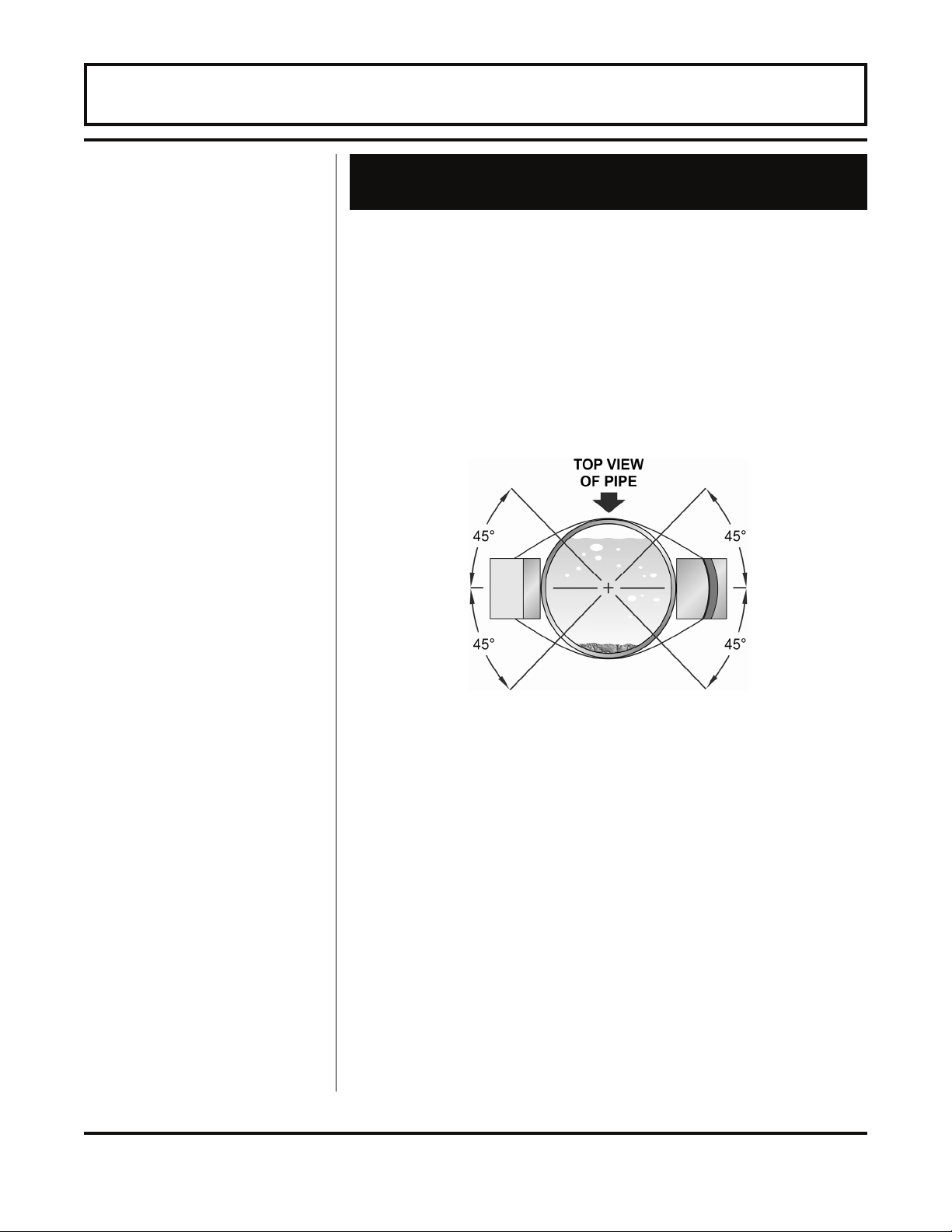
The transducers need to be properly oriented on the pipe to
provide optimum reliability and performance. On horizontal
pipes, the transducers should be mounted 180 radial degrees
from one another and at least 45 degrees from the top-deadcenter and bottom-dead-center of the pipe. See Figure 2.1.
Figure 2.1 does not apply to vertically oriented pipes.
Figure 2.1 Horizontal pipe transducer mounting
Pipe Preparation
- 2.14 - FDT-81
Before the transducers are bonded to the pipe surface, two
areas slightly larger than the flat surface of the transducer
heads must be cleaned of all rust, scale and moisture. For
pipes with rough surfaces, such as ductile iron pipe, it is
recommended that the pipe surface be ground flat. Paint and
other coatings, if not flaked or bubbled, need not be removed.
Plastic pipes typically do not require surface preparation
other than soap and water cleaning.
Page 31
PART 2 - TRANSDUCER POSITIONING
V-Mount and
W-mount
Transducer
Installation
Transducer Mounting - V-mount and W-mount
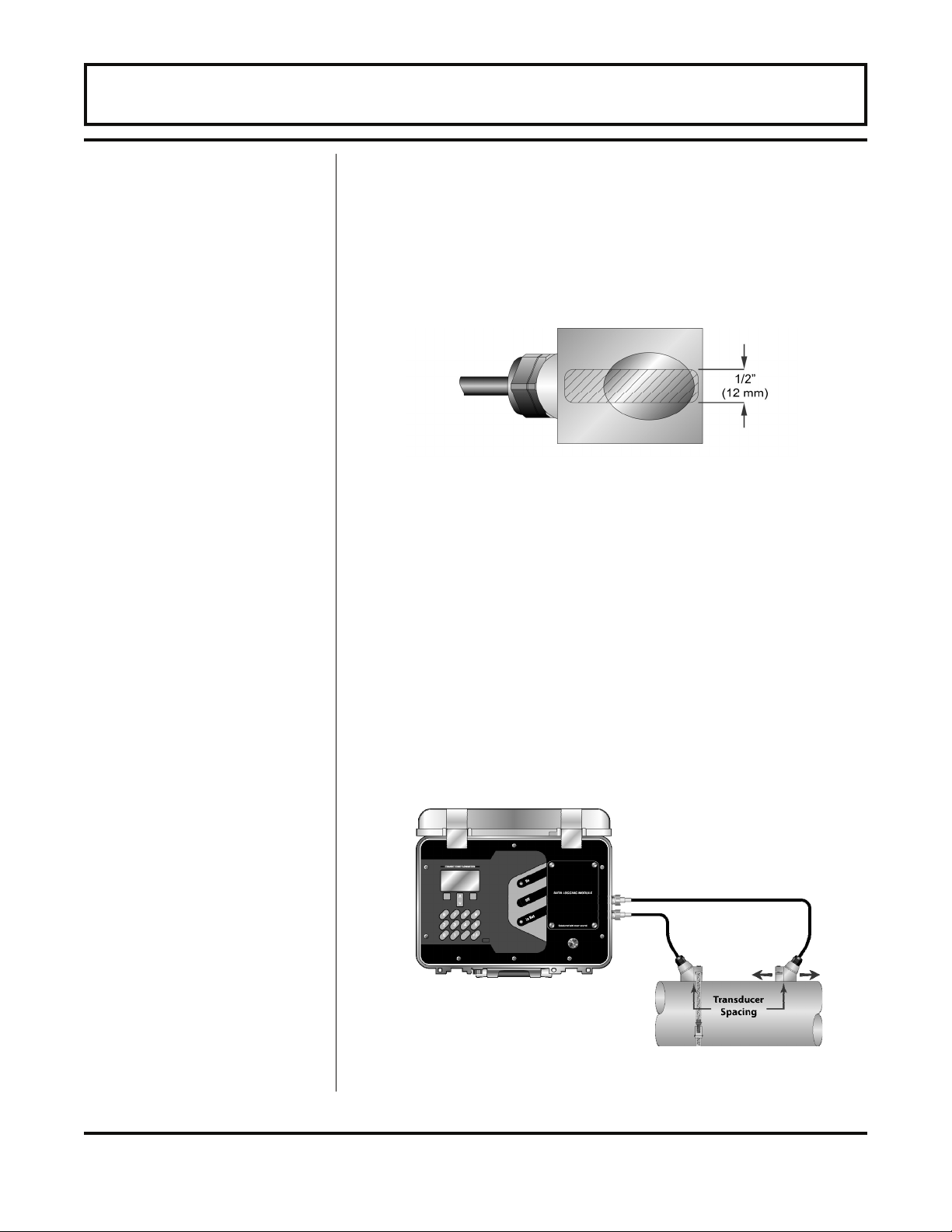
1. Place a single bead of couplant, approximately 0.50 inch
[12mm] thick, on the flat face of the transducer (Figure
2.2). Generally, a silicone-based grease is used as an
acoustic couplant, but any grease-like substance that is
rated not to “flow” at the temperature that the pipe may
operate at, will be acceptable.
Figure 2.2 Transducer Couplant Application
2. Place the upstream transducer in position and secure with
a mounting strap. The strap should be place in the
arched groove on end of transducer. A screw is provided
to help hold the transducer onto the strap. Verify that the
transducer is true to the pipe - adjust as necessary.
Tighten strap securely.
3. Place the downstream transducer on pipe at the
calculated transducer spacing. See Figure 2.3. Using
firm hand pressure, slowly move the transducer towards
and away from the upstream transducer while observing
Signal Strength. Clamp the transducer at the position
where the highest Signal Strength is observed. A Signal
Strength between 3.0 and 95.0 percent is acceptable.
(Top view of pipe)
Figure 2.3 Transducer Position
- 2.15 - FDT-81
Page 32
PART 2 - TRANSDUCER POSITIONING
4. If after adjustment of the transducers the Signal Strength
does not rise to above 5 percent, then an alternate
transducer mounting method should be selected. If the
mounting method was W-mode, then reconfigure the FDT-81
for V-mode, reset the FDT-81, move the downstream
transducer to the new location and repeat step 3.
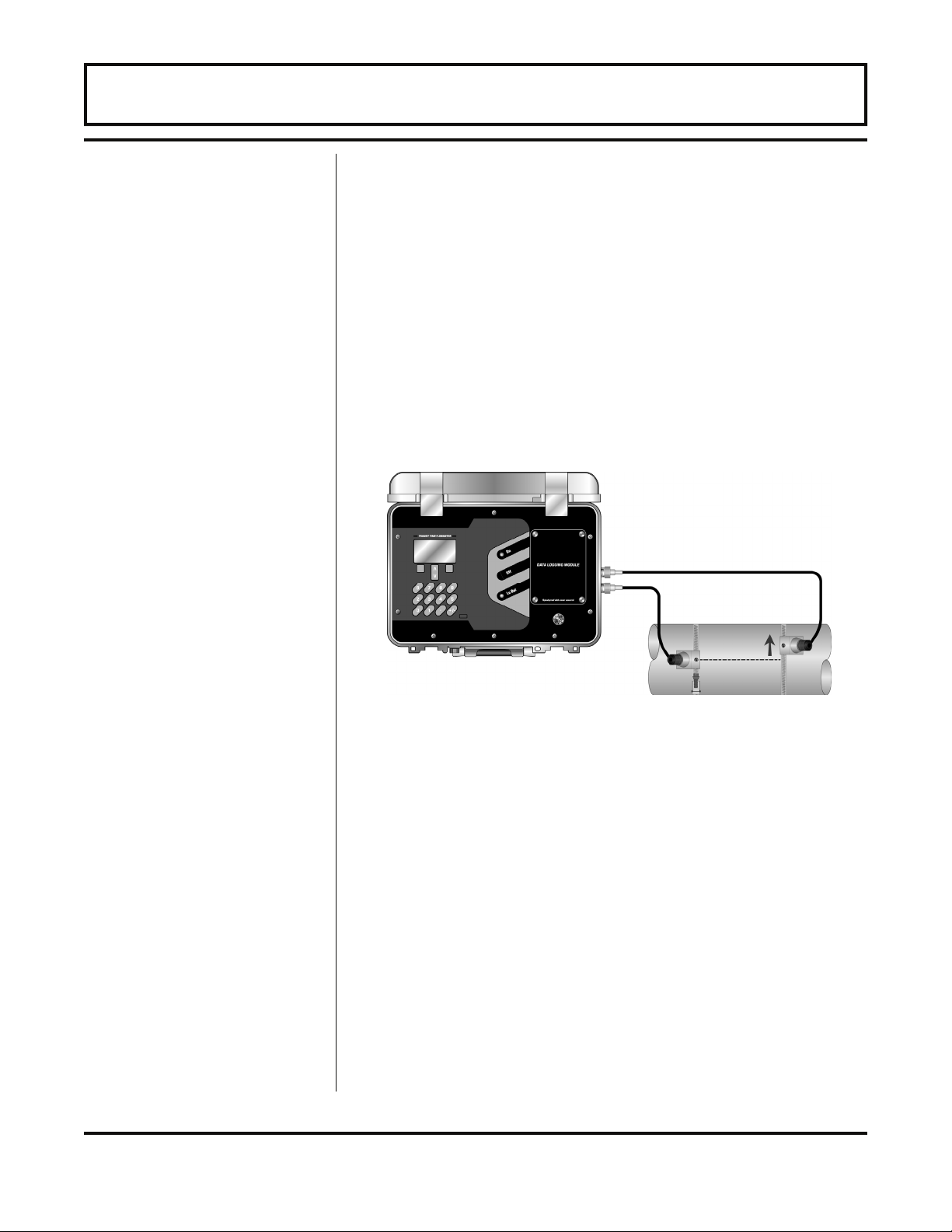
5. Certain pipe and liquid characteristics may cause Signal
Strength to rise to greater than 95%. The problem with
operating an FDT-81 with very high Signal Strength is
that the signals may saturate the input amplifiers and
cause erratic readings. To decrease the Signal
Strength, move one transducer a small distance radially
around the pipe, as shown in Figure 2.4.
Figure 2.4 High Signal Strength Condition
Z-Mount
Transducer
Installation
- 2.16 - FDT-81
Transducer Mounting in Z-Mount Configuration
Installation on larger pipes requires careful measurements to
linear and radial placement of transducers. Failure to
properly orient and place transducers on pipe may lead to
weak signal strength and/or inaccurate readings. The section
below details a method for properly locating transducers on
larger pipes. It requires a roll of paper (i.e. freezer or
wrapping paper), masking tape and a marking device.
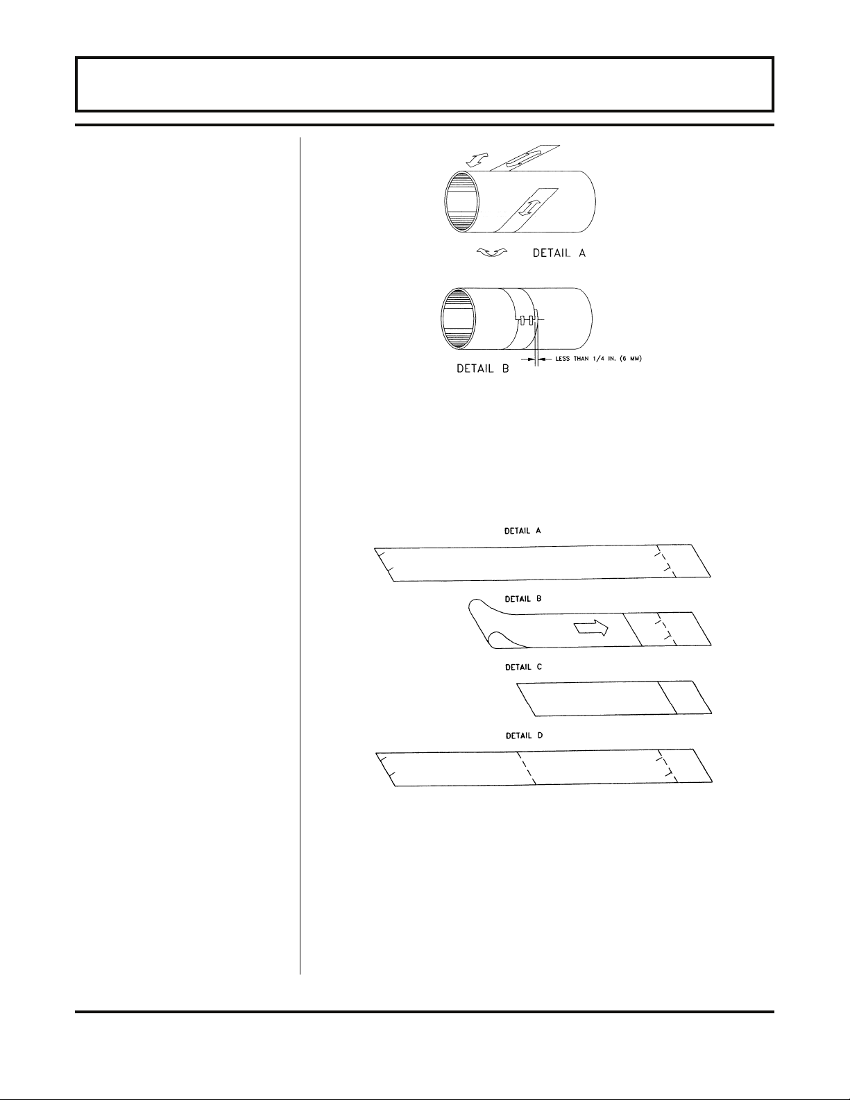
1. Wrap paper around pipe as shown in Figure 2.5. Align
the paper ends to within 0.25 inches [6mm].
Page 33
PART 2 - TRANSDUCER POSITIONING
Figure 2.5 Paper Template Alignment
2. Mark the intersection of the two ends of paper to indicate
the circumference. Remove the template and spread it out
on a flat surface. Fold template in half, bisecting the
circumference. See Figure 2.6.
Figure 2.6 Bisecting the pipe circumference
3. Crease the paper at the fold line. Mark the crease. Place a
mark on the pipe where one of the transducers will be
located. See Figure 2.1 for acceptable radial orientations.
Wrap the template back around the pipe, placing the
beginning of the paper and corner in the location of the
mark. Move to the other side of the pipe and mark the
- 2.17 - FDT-81
Page 34

PART 2 - TRANSDUCER POSITIONING
ends of the crease. Measure from the end of the crease
(directly across the pipe from the first transducer location)
the dimension derived in Step 2, Transducer Spacing.
Mark this location on the pipe.
4. The two marks on the pipe are now properly aligned and
measured.
If access to the bottom of the pipe prohibits the wrapping of
the paper around the circumference, cut a piece of paper
to these dimensions and lay it over the top of the pipe.
Length = Pipe O.D. x 1.57
Width = Spacing determined on 2.12 or 2.14
Mark opposite corners of the paper on the pipe. Apply
transducers to these two marks.
5. Place a single bead of couplant, approximately 0.50 inch
[12 mm] thick, on the flat face of the transducer. See
Figure 2.2. Generally, a silicone-based grease is used as
an acoustic couplant, but any grease-like substance that is
rated not to “flow” at the temperature that the pipe may
operate at, will be acceptable.
6. Place the upstream transducer in position and secure with
a stainless steel strap. Straps should be placed in the
arched groove on the end of the transducer. A screw is
provided to help hold the transducer onto the strap. Verify
that the transducer is true to the pipe—adjust as
necessary. Tighten transducer strap securely. Larger pipes
may require more than one strap to reach the
circumference of the pipe.
7. Place the downstream transducer on the pipe at the
calculated transducer spacing. See Figure 2.7. Using firm
hand pressure, slowly move the transducer both towards
and away from the upstream transducer while observing
Signal Strength. Clamp the transducer at the position
where the highest Signal Strength is observed. Signal
Strength of between 5 and 95 percent is acceptable. On
certain pipes, a slight twist to the transducer may cause
signal strength to rise to acceptable levels.
- 2.18 - FDT-81
Page 35
PART 2 - TRANSDUCER POSITIONING
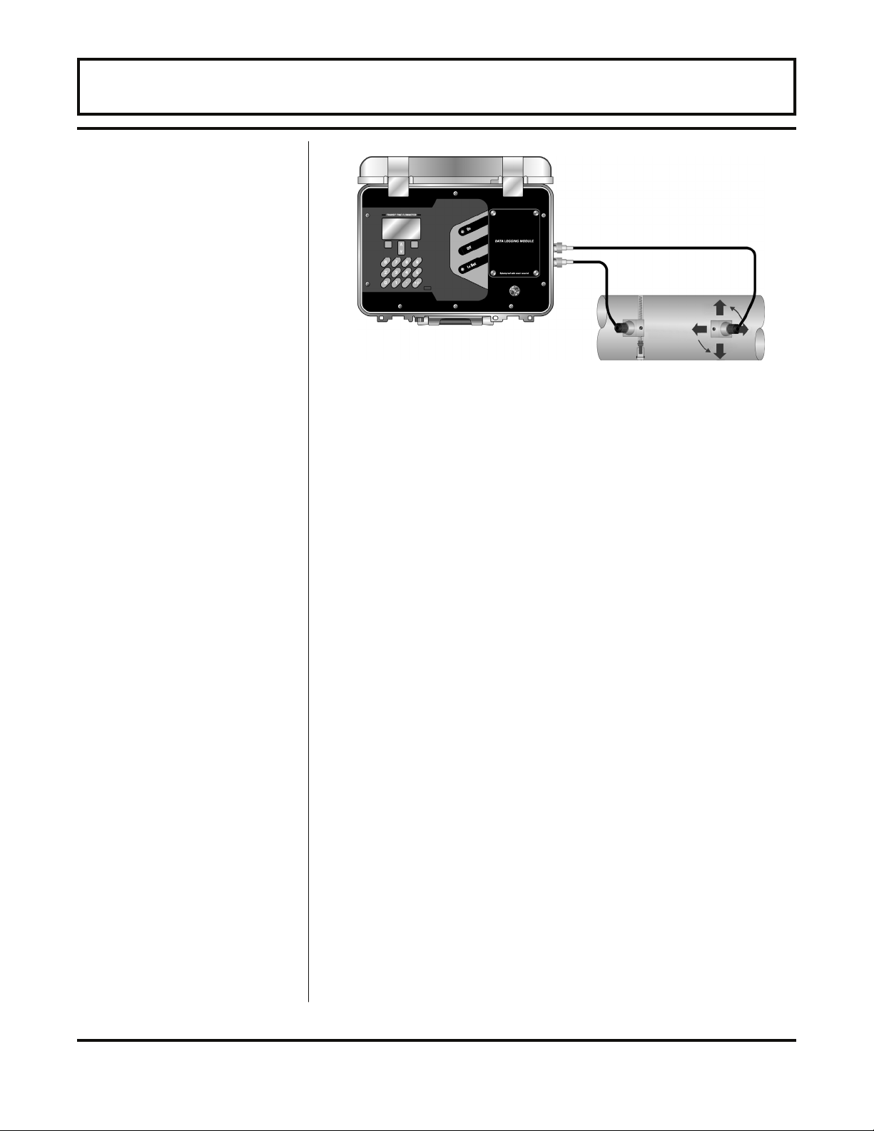
Figure 2.7 Z-Mode Transducer Placement
8. Certain pipe and liquid characteristics may cause Signal
Strength to rise to greater than 95%. The problem with
operating an FDT-81 with very high Signal Strength is
that the signals may saturate the input amplifiers and
cause erratic readings. To decrease the Signal
Strength one transducer can be offset radially, as
illustrated in Figure 2.4, or a V-Mode mounting method
may be chosen.
Mounting Track
Installation
9. Secure the transducer with a stainless steel strap.
Transducer Mounting - Mounting Track
1. The transducer mounting track is used for pipes that have
outside diameters between 2 and 10 inches [50-250mm].
If the pipe is outside of that range, then select a standard
V-mode or W-mode mounting method.
2. Install the mounting rail on the side of the pipe with the
stainless steel bands provided. Do not mount on the top
or bottom of the pipe. Orientation on vertical pipe is not
critical. Ensure that the track is parallel to the pipe and
that all four mounting feet are touching the pipe.
3. Slide the two transducer clamps towards the center, 5
inch [125 mm] mark, on the mounting rail.
4. Place a single bead of couplant, approximately 0.25 inch
[6 mm] thick, on the flat face of the transducer. See
Figure 2.2.
- 2.19 - FDT-81
Page 36
PART 2 - TRANSDUCER POSITIONING
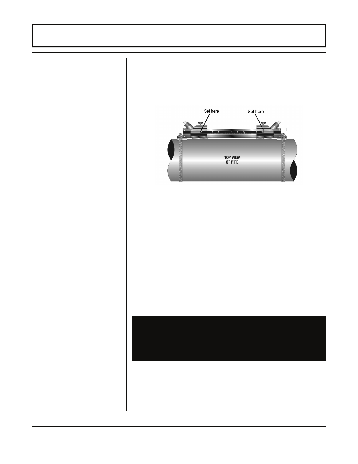
5. Place the first transducer in between the mounting rails
near the zero point on the mounting rail scale. Slide
clamp over the transducer. Adjust the clamp/transducer
so the notch in the clamp aligns with zero on the scale.
See Figure 2.8.
Figure 2.8 Transducer Space Measurement
6. Secure with the thumb screw. Ensure that the screw
rests in the counter bore on the top of the transducer.
(Excessive pressure is not required. Apply just enough
pressure so that the couplant fills the gap between the
pipe and transducer.)
Small Pipe
Transducer
Installation
7. Place the second transducer in between the mounting
rails near the dimension derived in the Transducer
Spacing section. Read the dimension on the mounting
rail scale. Slide the transducer clamp over the transducer
and secure with the thumb screw.
Transducer Mounting - Small pipe
Important note for pipe sizes under 2 inches [50 mm]. If the
transducer spacing that is calculated is lower than 2.65
inches [67 mm], a set of small pipe transducers are required.
Please contact Omega for information regarding the small
pipe transducers.
The small pipe transducers offered by Omega are designed
for specific pipe outside diameters. Do not attempt to mount
a small pipe transducer onto a pipe that is either too large or
too small for the transducer - contact Omega to inquire about
small pipe transducers that are the correct size.
- 2.20 - FDT-81
Page 37
PART 2 - TRANSDUCER POSITIONING
Small pipe transducer installation consists of the following
steps:
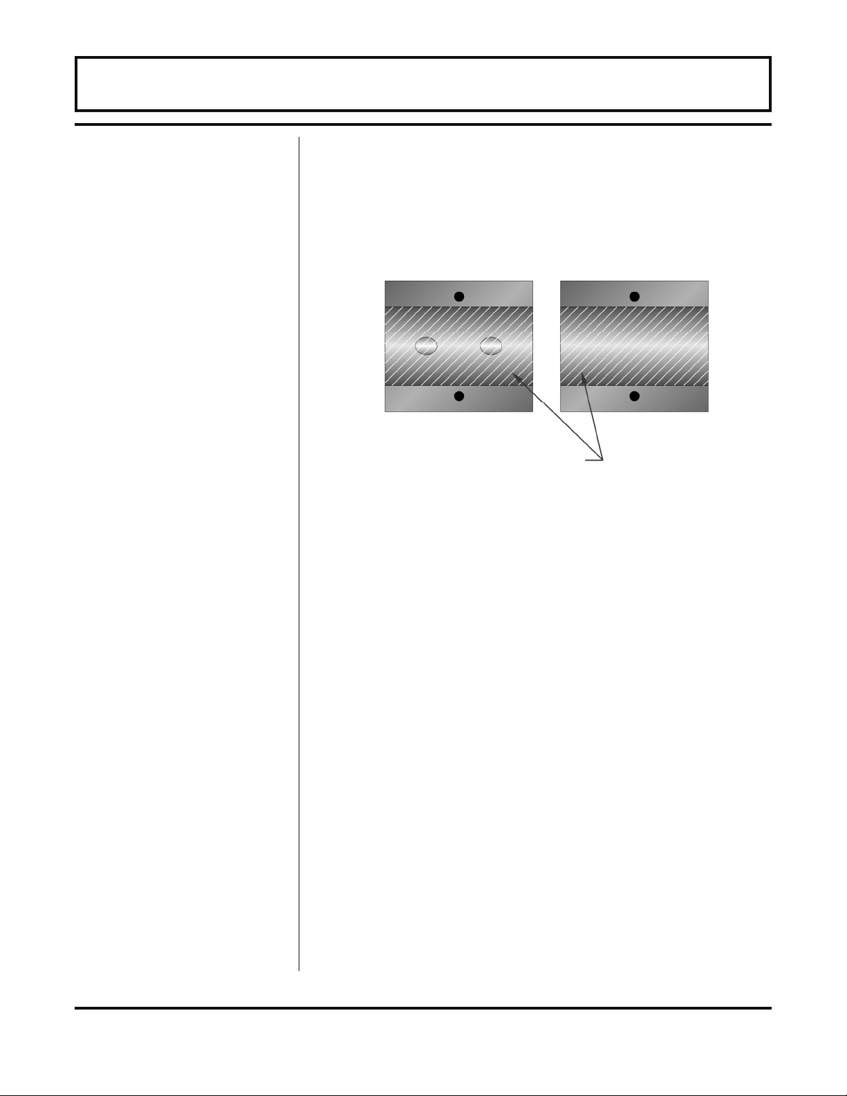
1. Apply a thin coating of silicone grease to both halves of
the transducer housing where the housing will contact the
pipe. See Figure 2.9.
1/16" [1.5mm] MAGNALUBE GREASE
Figure 2.9 Application of Grease
Small PipeTransducer
2. On horizontal pipes, mount the transducer in an
orientation such that the cable exits at ±45° from the side
of the pipe. Do not mount with the cable exiting on either
the top or bottom of the pipe. On vertical pipes the
orientation does not matter.
3. Tighten the wing nuts so that the grease begins to flow
out from the edges of the transducer and from the gap
between the transducer halves. Do not over tighten.
4. If Signal Strength is less than 5%, remount the transducer
at another location on the piping system.
5. If Signal Strength is greater than 95%, contact the factory
to obtain a lower power Strategy to load into the FDT-81
flow meter.
- 2.21 - FDT-81
Page 38

PART 3 - STARTUP AND CONFIGURATION
Before Starting the
Instrument
Instrument Startup
Note: The FDT-81 flow meter system requires a full pipe
of liquid before a successful startup can be completed.
Do not attempt to make adjustments or change
configurations until a full pipe is verified.
Note: If Dow 111 silicone grease was utilized as a couplant,
a curing time is not required. However, if Dow 732 or another
permanent RTV was used, the adhesive must fully cure before power is applied to the instrument.
Procedure:
1. Verify that all wiring is properly connected and routed as
described previously in this manual.
2. Verify that the transducers are properly mounted as
described in Part 2 of this manual.
3. Press the ON button on the flow meter keypad. The FDT-81
display backlighting will illuminate and the software version
number will appear on the display.
The display backlighting illuminates for approximately 20
seconds and automatically extinguishes to preserve battery
power. To re illuminate the display, press any key on the
keyboard. Adjustments to the backlighting duration can be
made in the Display Menu. Refer to page 3.24 for details.
4. Confirm that Signal Strength is greater than 2%. If it is
not, verify that proper transducer mounting methods and
liquid/pipe characteristics have been entered. The pipe
must be full of liquid in order to make this
measurement.
5. Once the meter is properly operating (proper signal
strength has been achieved), refer to the later portions of
this manual section for additional programming features.
- 3.1 - FDT-81
Page 39
PART 3 - KEYPAD CONFIGURATION
General
Keypad Operation
After an installation of the transducers and connection of
appropriate power supplies to the FDT-81, keypad
configuration of the instrument can be undertaken. All entries
are saved in non-volatile FLASH memory and will be retained
in the event of power loss.
The FDT-81 can be configured through the keypad interface.
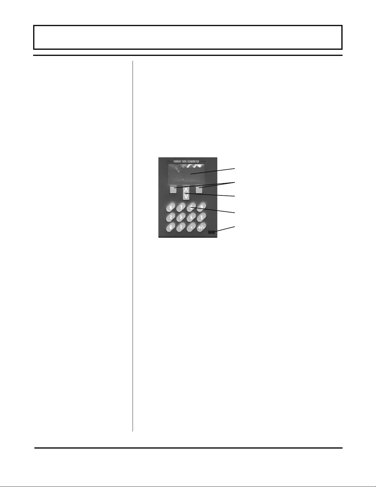
The following “Soft Key” menu items will be displayed
immediately above the two keys located in the lower corners
of the Graphics Display. See Figure 3.1.
Graphics Display
Soft Keys
Arrow Keys
Numeric Keys
Infrared Communications Port
Display Contrast
Figure 3.1
1. The MENU key is pressed from RUN mode to enter
PROGRAM mode. The EXIT key is pressed in
PROGRAM mode to exit configuration parameters and
menus. If changes to any configuration parameters have
been made, the user will be prompted with a SAVE? YES
or NO when returning to RUN mode. If no changes have
been made, the user will not be prompted to SAVE.
2. The UP/DOWN ARROW keys are used to scroll through
menus and configuration parameters. The ARROW keys
can also be used to adjust parameter numerical values or
to adjust the display contrast level in RUN mode.
3. The Numerical Keypad is used for entering numerical
values.
4. The ACCEPT key is used to
• accept configuration parameter changes.
- 3.2 - FDT-81
Page 40

PART 3 - KEYPAD CONFIGURATION
Graphics Display
Configuration
5. The SELECT key is used to
• Configure the engineering units on the graphics
display—Press the SELECT key from RUN mode
to highlight the engineering unit presently being
displayed on the graphics display (pressing the
SELECT key multiple times will toggle the
highlighted unit from line to line). Use the UP/
DOWN ARROW keys to select display units of
• N - Total (Net Totalizer)
• + - Total (Positive Totalizer)
• - - Total (Negative Totalizer)
• Rate
• Sound Speed FPS
• Sound Speed MPS
• SIGNAL STR.
• Temp 1
• Temp 2
• Temp DIFF
From Menu 8, Display Menu, the number of graphics
display lines can be toggled between two and four lines.
• access the configuration parameters in the various
menus.
• initiate changes in configuration parameters.
- 3.3 - FDT-81
Page 41

PART 3 - KEYPAD CONFIGURATION
Menu Structure
The eight menus used in the structure of the FDT-81 are as
follows:
1. BSC MENU -- BASIC operations menu. Contains all of
the configuration parameters necessary to program the
meter to measure flow.
2. OUT2 MEN -- Configures the type and operating
parameters of the 4-20mA or other ISO-MOD located
internally in the FDT-81 flow meter.
3. SEN MENU -- Selects the transducer type (i.e. FDT-81-
STD, FDT-81-HTl, etc.).
4. SEC MENU -- Resets totalizers, resets the operating
system and revises security passwords.
5. SER MENU -- SERVICE MENU contains system
measurements that are used by service personnel for
troubleshooting.
6. DSP MENU -- Configures meter display functions.
The following sections define the configuration parameters
located in each of the menus.
UNITS Selection
The BASIC menu contains all of the configuration parameters
necessary to make the FDT-81 operational.
1. BSC MENU -- BASIC MENU
UNITS
ENGLSH
METRIC
Installs a global measurement standard into the operation of
the instrument. The choices are either English or Metric
measurements.
• Select ENGLSH if all configurations (pipe sizes, etc.)are
to be made in inches. Select METRIC if the meter is to be
configured in millimeters.
- 3.4 - FDT-81
Page 42

PART 3 - KEYPAD CONFIGURATION
Transducer Mount
Pipe Diameter
• The ENGLSH/METRIC selection will also configure the
FDT-81 to display sound speeds in pipe materials and
liquids as either feet per second or meters per second,
respectively.
NOTE: If the UNITS entry has been changed from ENGLSH
to METRIC or from METRIC to ENGLSH, the entry must be
saved and the instrument reset (power cycled or System
Reset entered) in order for the FDT-81 to initiate the change in
operating units. Failure to save and reset the instrument will
lead to improper transducer spacing calculations and an
instrument that may not measure properly.
XDCR MNT -- Transducer Mounting Method
V
W
Z
Selects the mounting orientation for the transducers. The
selection of an appropriate mounting orientation is based on
pipe and liquid characteristics. See PART 2 - Transducer
Installation in this manual.
PIPE OD -- Pipe Outside Diameter Entry
ENGLSH (Inches)
METRIC (Millimeters)
Enter the pipe outside diameter in inches if ENGLSH was
selected as UNITS; in millimeters if METRIC was selected.
NOTE: Charts listing popular pipe sizes have been included in
the Appendix of this manual. Correct entries for pipe P.D. and
pipe wall thickness are critical to obtaining accurate flow
measurement readings.
- 3.5 - FDT-81
Page 43

PART 3 - KEYPAD CONFIGURATION
Pipe Wall
Thickness
Pipe Material
Pipe Sound Speed
PIPE WT -- Pipe Wall Thickness Entry
ENGLSH (Inches)
METRIC (Millimeters)
Enter the pipe wall thickness in inches if ENGLSH was
selected as UNITS; in millimeters if METRIC was selected.
PIPE MAT -- Pipe Material Selection
CARBON S - Carbon Steel
STAINLES - Stainless Steel
CAST IRO - Cast Iron
DUCTILE - Ductile Iron
COPPER - Copper
PVC - Polyvinylchloride
PVDF LOW - Low Density Polyvinylidene Flouride
PVDF HI - High Density Polyvinylidene Flouride
ALUMINUM - Aluminum
FIBERGLA - Fiberglass
OTHER
This list is provided as an example. Additional pipe materials
are being added continuously. Select the appropriate pipe
material from the list or select OTHER if the material is not
listed.
PIPE SS -- Speed of Sound in the Pipe Material
ENGLSH (Feet per Second)
METRIC (Meters per Second)
Allows adjustments to be made to the speed of sound in the
pipe wall. If the UNITS value was set to ENGLSH, the entry is
in FPS (feet per second). METRIC entries are made in MPS
(meters per second).
If a pipe material was chosen from the PIPE MAT list, a
nominal value for speed of sound in that material will be
automatically loaded. If the actual sound speed rate is
known for the application piping system and that value varies
from the automatically loaded value, the value can be
revised.
If OTHER was chosen as PIPE MAT, a PIPE SS will need to
be entered.
- 3.6 - FDT-81
Page 44

PART 3 - KEYPAD CONFIGURATION
Pipe Roughness
Liner Thickness
Liner Material
PIPE R -- Pipe Material Relative Roughness
UNITLESS VALUE
The FDT-81 provides Reynolds Number compensation in its
flow measurement calculation. The ratio of average surface
imperfection as it relates to the pipe internal diameter is used
in this compensation.
Linear RMS measurement of the pipe
PIPE R = internal wall surface
Internal Diameter of the pipe
If a pipe material was chosen from the PIPE MAT list, a
nominal value relative roughness in that material will be
automatically loaded. If the actual roughness is known for
the application piping system and that value varies from the
automatically loaded value, the value can be revised.
If OTHER was chosen as PIPE MAT, a PIPE R may to be
entered.
LINER T -- Pipe Liner Thickness Entry
ENGLSH (Inches)
METRIC (Millimeters)
Enter the pipe liner thickness. Enter this value in inches if
ENGLSH was selected as UNITS; in millimeters if METRIC
was selected.
[If a LINER Thickness was selected]
LINER MAT - Liner Material
TAR EPOXY
RUBBER
MORTAR
POLYPROPYLENE
POLYSTYROL
POLYSTYRENE
POLYESTER
POLYETHYLENE
EBONITE
PTFE or PFA
OTHER
This list is provided as an example. Additional materials are
- 3.7 - FDT-81
Page 45

PART 3 - KEYPAD CONFIGURATION
Liner Sound Speed
Fluid Type
Fluid Sound Speed
being added continuously. Select the appropriate material
from the list or select OTHER if the liner material is not listed.
LINER SS -- Speed of Sound in the Liner
ENGLSH (Feet per Second)
METRIC (Meters per Second)
Allows adjustments to be made to the speed of sound in the
liner. If the UNITS value was set to ENGLSH, the entry is in
FPS (feet per second). METRIC entries are made in MPS
(meters per second).
If a liner was chosen from the LINER MAT list, a nominal
value for speed of sound in that media will be automatically
loaded. If the actual sound speed rate is known for the pipe
liner and that value varies from the automatically loaded
value, the value can be revised.
FL TYPE - Fluid/Media Type
TAP WATER
SEA WATER
KEROSENE
GASOLINE
FUEL OIL
CRUDE OIL
PROPANE
BUTANE
OTHER
This list is provided as an example. Additional liquids are
being added continuously. Select the appropriate liquid from
the list or select OTHER if the liquid is not listed.
FLUID SS -- Speed of Sound in the Fluid
ENGLSH (Feet per Second)
METRIC (Meters per Second)
Allows adjustments to be made to the speed of sound in the
liquid. If the UNITS value was set to ENGLSH, the entry is in
FPS (feet per second). METRIC entries are made in MPS
(meters per second).
If a fluid was chosen from the FL TYPE list, a nominal value
for speed of sound in that media will be automatically loaded.
- 3.8 - FDT-81
Page 46

PART 3 - KEYPAD CONFIGURATION
Fluid Viscosity
If the actual sound speed rate is known for the application
fluid and that value varies from the automatically loaded
value, the value can be revised.
If OTHER was chosen as FL TYPE, a FLUID SS will need to
be entered. A list of alternate fluids and their associated
sound speeds are located the Appendix located at the back
of this manual.
FLUID VI -- Absolute Viscosity the Fluid
cps
Allows adjustments to be made to the absolute viscosity of
the liquid. If a fluid was chosen from the FL TYPE list, a
nominal value for viscosity in that media will be automatically
loaded. If the actual viscosity is known for the application fluid
and it varies from the automatically loaded value, the value
can be revised.
Fluid Specific
Gravity
If OTHER was chosen as FL TYPE, a FLUID VI will need to
be entered. A list of alternate fluids and their associated
viscosities are located in the Appendix located at the back of
this manual.
SP GRVTY -- Fluid Specific Gravity Entry
unitless
Allows adjustments to be made to the specific gravity
(density) of the liquid. If a fluid was chosen from the FL
TYPE list, a nominal value for specific gravity in that media
will be automatically loaded. If the actual specific gravity is
known for the application fluid and that value varies from the
automatically loaded value, the value can be revised.
If OTHER was chosen as FL TYPE, a SP GRVTY may need
to be entered if mass flows are to be calculated. A list of
alternate fluids and their associated specific gravities are
located the Appendix located at the back of this manual.
- 3.9 - FDT-81
Page 47

PART 3 - KEYPAD CONFIGURATION
Transducer Spacing
Engineering Units
RATE
Engineering Units
RATE INTERVAL
XDCR SPAC -- Transducer Spacing Calculation
ENGLSH (Inches)
METRIC (Millimeters)
This value represents the one-dimensional linear
measurement between the transducers (the upstream/
downstream measurement that runs parallel to the pipe).
This value is in inches if ENGLSH was selected as UNITS; in
millimeters if METRIC was selected. This measurement is
taken from the line which is scribed into the side of the
transducer block.
If the transducers are being mounted using the transducer
track assembly, a measuring scale is etched into the track.
Place on transducer at 0 inches and the other at the
appropriate measurement.
RATE UNT - Engineering Units for Flow Rate
GALLONS - U.S. Gallons
LITERS - Metric Liter
MGAL - Millions of U.S. Gallons
CUBIC FT - Cubic Feet
CUBIC ME - Cubic Meters
ACRE FT - Acre Feet
OIL BARR - Oil Barrels (42 U.S. Gallons)
LIQ BARR - Liquor Barrels (31.5 U.S. Gallons)
FEET - Linear Feet
METERS - Linear Meters
Select a desired engineering unit for flow rate measurements.
RATE INT - Time Interval for Flow Rate
MIN - Minutes
HOUR - Hours
DAY - Days
SEC - Seconds
Select a desired engineering unit for flow rate measurements.
- 3.10 - FDT-81
Page 48
PART 3 - KEYPAD CONFIGURATION
Engineering Units
TOTALIZER
Engineering Units
TOTAL Exponent
TOTL UNT - Engineering Units for Flow Totalizer
GALLONS - U.S. Gallons
LITERS - Metric Liter
MGAL - Millions of U.S. Gallons
CUBIC FT - Cubic Feet
CUBIC ME - Cubic Meters
ACRE FT - Acre Feet
OIL BARR - Oil Barrels (42 U.S. Gallons)
LIQ BARR - Liquor Barrels (31.5 U.S. Gallons)
FEET - Linear Feet
METERS - Linear Meters
Select a desired engineering unit for flow accumulator
(totalizer) measurements.
TOTL E - Flow Totalizer Exponent Value
E-1 to E6
Utilized for setting the flow totalizer exponent. This feature is
useful for accommodating a very large accumulated flow.
The exponent is a ×10n multiplier, where "n" can be from -1
(×0.1) to +6 (×1,000,000). Table 3.1 should be referenced for
valid entries and their influence on the FDT-81 display.
TABLE 3.1—Totalizer Exponent Values
Exponent Display Multiplier
E-1
E0
E1
E2
E3
E4
E5
E6
× 0.1
× 1 (no multiplier)
× 10
× 100
× 1,000
× 10,000
× 100,000
× 1,000,000
- 3.11 - FDT-81
Page 49

PART 3 - KEYPAD CONFIGURATION
Minimum
Flow Rate
Maximum
Flow Rate
Low Flow Cut-off
System Damping
MIN RATE - Minimum Flow Rate Settings
Rate Unit/Rate Interval
A minimum volumetric flow rate setting is entered to establish
filter software settings. Volumetric entries will be in the
Engineering Rate Units and Interval selected on pages 3.10-
3.11 of this manual. For unidirectional measurements, set
MIN RATE to zero. For bi-directional measurements, set to
the highest negative (reverse) flow rate expected in the
piping system.
MAX RATE - Maximum Flow Rate Settings
Rate Unit/Rate Interval
A maximum volumetric flow rate setting is entered to
establish filter software settings. Volumetric entries will be in
the Engineering Rate Units and Interval selected on pages
3.10-3.11 of this manual. For unidirectional or bi-directional
measurements, set MAX RATE to the highest (positive) flow
rate expected in the piping system.
FL C-OFF - Low Flow Cut-off
Percent of the range between MIN RATE and MAX
RATE
A Low Flow Cut-off entry is provided to allow very low flow
rates (that can be present when pumps are off and valves are
closed) to be displayed as Zero flow. Typical values that
should be entered are between 1.0% and 5.0% of the flow
range between MIN RATE and MAX RATE.
DAMP PER - System Damping
Relative Percent Entry: 0-100%
Flow Filter Damping establishes a maximum adaptive filter
value. Under the stable flow conditions (flow varies less than
10% of reading) this adaptive filter will increase the number
of successive flow readings that are averaged together up to
this maximum value. If flow changes outside of the 10%
window, the Flow Filter adapts by decreasing and allows the
meter to react faster. Increasing this value tends to provide
smoother steady-state flow readings and outputs.
- 3.12 - FDT-81
Page 50

PART 3 - KEYPAD CONFIGURATION
2. OUTPUT 2 MENU
Standard
4-20mA
4-20mA Span
ISO-MOD 4-20mA
FL 4MA
FL 20MA
CAL 4MA
CAL 20MA
4-20 TST
Configured via jumper selections for either a passive or
active transmission mode, the 4-20mA Output Module
interfaces with virtually all recording and logging systems by
transmitting an analog current signal that is proportional to
system flow rate. Independent 4mA and 20mA span settings
are established in software using the Flow Measuring Range
entries. These entries can be set anywhere in the –40 to +40
FPS [-12 to +12 MPS] measuring range of the instrument.
Output resolution of the module is 12-bits (4096 discrete
points) and the module can drive up to 800 ohms of load with
its internal 24V isolated power source.
The FL 4MA and FL 20MA entries are used to set the span
of the 4-20mA analog output. These entries are volumetric
rate units that are equal to the volumetric units configured as
Engineering Rate Units and Engineering Units Time Interval
entered on page 3.10.
For example, to span the 4-20mA output from –100 GPM to
+100 GPM, with 12mA being 0 GPM, set the FL 4MA and FL
20MA inputs as follows:
FL 4MA = -100.0
FL 20MA = 100.0
For example, to span the 4-20mA output from 0 GPM to +100
GPM, with 12mA being 50 GPM, set the FL 4MA and FL
20MA inputs as follows:
FL 4MA = 0.0
FL 20MA = 100.0
- 3.13 - FDT-81
Page 51

PART 3 - KEYPAD CONFIGURATION
4-20mA Calibration
The 4-20mA ISO-MOD is factory calibrated and should not
require adjustment unless it is replaced.
The CAL4MA entry allows fine adjustments to be made to the
“zero” of the 4-20mA output. To adjust the 4mA output, an
ammeter or reliable reference connection to the 4-20mA
output must be present.
NOTE: The CAL 4MA and CAL 20MA entries should not be
used in a attempt to set the 4-20mA range. Utilize FL 4MA
and FL 20MA, detailed above, for this purpose.
Procedure:
1. Disconnect one side of the current loop and connect the
ammeter in series (disconnect either wire at the terminals
labeled +/- on the ISO-MOD 4-20mA module).
2. Using the arrow keys, increase the numerical value to
increase the current in the loop to 4mA. Decrease the
value to decrease the current in the loop to 4mA. Typical
values range between 40-80 counts.
Re connect the 4-20mA output circuitry as required.
Calibration of the 20mA setting is conducted much the same
way as the 4mA adjustments.
Procedure:
1. Disconnect one side of the current loop and connect the
ammeter in series (disconnect either wire at the terminals
labeled +/- on the ISO-MOD 4-20mA module).
2. Using the arrow keys, increase the numerical value to
increase the current in the loop to 20mA. Decrease the
value to decrease the current in the loop to 20mA.
Typical values range between 3700-3900 counts.
Re connect the 4-20mA output circuitry as required.
- 3.14 - FDT-81
Page 52

PART 3 - KEYPAD CONFIGURATION
4-20mA Test
Optional Modules
Optional
Rate Pulse
Rate Pulse Span
4-20 TST - 4-20mA Output Test
4-20
Allows a simulated value to be output on from the 4-20mA
output. By incrementing this value, the 4-20mA output will
transmit the indicated current value.
The Series FDT-81 allows other input/output modules to be
used in place of the 4-20mA output. Please contact the
Omega regarding these options:
ISO-MOD RATE PULSE
FL 0H
FL 25KH
The Rate Pulse Output Module is utilized to transmit
information to external counters and PID systems via a
frequency output that is proportional to system flow rate.
Independent Zero and Span settings are established in
software using the Flow Measuring Range entries. Output
resolution of the module is 12-bits (4096 discrete points) and
the maximum output frequency setting is 2,500Hz. The
module has two output modes, turbine meter simulation and
“open collector”. The turbine meter simulation sources a non
-ground referenced saw-tooth waveform with a maximum
peak amplitude of approximately 500mVpp. The opencollector output utilizes a 0.21-Ohm FET output that is rated
to operate at 100 V and 1 A maximum. If the open-collector
output type is utilized, an external voltage source and limit
resistor must be present.
The FL 0H and FL 25KH entries are used to set the span of
the 0-2.5KHz frequency output. These entries are volumetric
rate units that are equal to the volumetric units configured as
Engineering Rate Units and Engineering Units Time Interval
entered on page 3.11.
- 3.15 - FDT-81
Page 53

PART 3 - KEYPAD CONFIGURATION
In a bi-directional system, to span the 0-2.5kHz output from –
100 GPM to +100 GPM, with 1.25kHz being 0 GPM, set the
FL 100H and FL 10KH inputs as follows:
FL 0H = 100.0
FL 25KH = 100.0
To span the 0-2.5 kHz output from 0 GPM to +100 GPM, with
1.25 kHz being 50 GPM, set the FL 0H and FL 25KH inputs
as follows:
FL 0H = 0
FL 25KH = 100.0
Optional
Dual Relay
Batch/Totalizer
Relay
ISO-MOD Dual Relay
RELAY 1 AND RELAY 2
NONE
TOTALIZE
TOT MULT
FLOW
ON
OFF
SIG STR
ERRORS
Two independent SPDT (single-pole, double-throw, Form C)
relays are contained in this module. The relay operations are
user configured via software to act in either a flow rate alarm,
signal strength alarm, error alarm or totalizer/batching mode.
The relays are rated for 200 VAC max. and a have current
rating of 0.5A resistive load [175 VDC @ 0.25A resistive]. It
is highly recommended that a secondary relay be utilized
whenever the Control Relay ISO-MOD is used to control
inductive loads such as solenoids and motors.
TOTALIZE mode configures the relay to output a 50 mSec
pulse (contact changeover) each time the display totalizer
increments—divided by the TOT MULT. The TOT MULT
value must be a whole, positive, numerical value.
• If the Totalizer Exponent is set to E0 (x1) and the Relay
Multiplier is set to 1, then the relay will pulse each time
the totalizer increments one count, or each single, whole
measurement unit totalized.
- 3.16 - FDT-81
Page 54
PART 3 - KEYPAD CONFIGURATION
Flow Rate Relay
• If the Totalizer Exponent is set to E2 (x100) and the Relay
Multiplier is set to 1, then the relay will pulse each time
the display totalizer increments or once per 100
measurement units totalized.
• If the Totalizer Exponent is set to E0 (x1) and the Relay
Multiplier is set to 2, the relay will pulse once for every two
counts that the totalizer increments.
Flow rate relay configuration permits relay changeover at two
separate flow rates, allowing operation with an adjustable
switch deadband. Figure 3.2 illustrates how the setting of the
two set points influences Rate Alarm operation.
A single-point flow rate alarm would place the ON> setting
slightly higher than the OFF< setting -allowing a switch
deadband to be established. If a deadband is not established,
switch chatter (rapid switching) may result when flow rate is
too close to the switch point.
Minimum flow Maximum flow
Signal Strength
Alarm
Relay ON
Set OFF <
Relay OFF
Deadband
Set ON >
Figure 3.2
Single Point Alarm Operation
The SIG STR alarm will provide an indication that the flow
meter signals between the transducers have fallen to a point
where flow measurements may not be possible. It can also
be used to indicate the pipe has emptied. Like the Flow Rate
alarm described previously, the Signal Strength alarm
requires that two points be entered, establishing an alarm
deadband. A valid switch point exists when the ON> is a
value lower than OFF<. If a deadband is not established and
the signal strength decreases to approximately the value of
the switch point, the relay may chatter.
- 3.17 - FDT-81
Page 55

PART 3 - KEYPAD CONFIGURATION
Error Alarm Relay
Optional
RS232C Module
Optional
RS-485 Module
If a relay is set to ERROR mode, the relay will activate when
errors occur in the flow meter that has caused the meter to
stop measuring reliably. See Appendix for a list of potential
error codes.
ISO-MOD RS-232C
RS232 MO — MODE
HOST
UIF
RS232 BA — BAUD RATE
1200
2400
9600
19200
The RS232 Module can be interfaced with serial communication
ports of PCs, PLCs and SCADA systems. The module runs a
proprietary digital protocol, detailed in the Appendix, that is
used to monitor flow rate information in piping systems.
ISO-MOD RS-485
RS485 MO — MODE
SLAVE
MASTER
RS485 BA — BAUD RATE
1200
2400
9600
19200
ADDRESS — Device Address
1-127
The RS485 Module allows up to 126 FDT-81 systems to be
daisy-chained on a single three-wire cable network.
Communications are via a proprietary digital protocol,
detailed in the Appendix. All meters are assigned a unique
one byte serial number that allows all of the meters on the
cable network to be accessed independently. Baud rates up
to 19.2K and cable lengths to 5,000 feet [1,500 meters] are
supported without the need for repeaters.
- 3.18 - FDT-81
Page 56

PART 3 - KEYPAD CONFIGURATION
PART 3 - KEYPAD CONFIGURATION
RS485 MO
Select SLAVE for all of the FDT-81 meters.
RS485 BA
Select a Baud rate that is compatible with the operating
system.
ADDRESS
Each FDT-81 connected on the communications bus must
have a unique address number assigned. Address 127 is a
universal address that will result in all FDT-81 instruments on
the network responding simultaneously—regardless of
address—resulting in CRC errors. Only select address
location 127 if one meter is on the network.
3. SEN MENU -- SENSOR MENU
Totalizer RESET
System RESET
The SEN MENU is utilized to select the type of transducer
that will be interfaced with the FDT-81 meter. Select the
appropriate transducer from the list and save the
configuration. If the transducer selection is modified, a
system reset is required.
4. SEC MENU -- SECURITY MENU
SEC MENU allows users to make password revisions, reset
flow totalizer and reset transmitter microprocessor.
TOT RES
NO
YES
Select YES to reset flow totalizer/accumulator to Zero.
SYS RSET
NO
YES
Select YES to initiate a microprocessor reset. All
configurations and totalizer values will be maintained.
- 3.19 - FDT-81
Page 57

PART 3 - KEYPAD CONFIGURATION
Change Password
Liquid Sound
Speed
CH PSWD? -- Change the Security Password
0-9999
By changing the Security Password from 0 to another value
(between 1-9999), configuration parameters will not be
accessible without first entering that value when prompted. If
the value is left at 0, no security is invoked and unauthorized
changes could be made.
5. SER MENU -- SERVICE MENU
The SERVICE Menu makes available two different system
measurements that are used for trouble-shooting and fine
tuning of the instrument. Actual liquid sound speed and
system signal strength readings can be accessed through
this menu.
The SERVICE Menu also has features that allow adjustment
of Signal Strength Cutoff, Error-Mode outputs, Zero Flow
Rate Set and entry of a universal correction factor.
SSPD MPS - Sound Speed in the Liquid Metric
SSPD FPS - Sound Speed in the Liquid U.S.
The FDT-81 performs an actual speed of sound calculation
for the liquid it measures. This calculation will vary with
temperature, pressure and fluid composition. The value
indicated should be within 2% of the value entered/indicated
in the BASIC menu item FLUID SS. The value cannot be
modified. If the actual measured value is significantly different
than the BASIC MENU’s FLUID SS value, it typically
indicates a problem with the instrument setup. Any entry such
as PIPE OD or wall thickness may be in error, the pipe may
not be round, or the transducer spacing is not correct. Table
3.3 on page 3.21 lists sound speed values for water at
varying temperatures. If the FDT-81 is measuring sound
speed within 2% of the table values, then the installation and
setup of the instrument is correct and accurate readings may
be assured.
- 3.20 - FDT-81
Page 58
PART 3 - KEYPAD CONFIGURATION
Table 3.3
Sound Speed in
Liquid water vs.
Temperature
Deg. C Deg. F Vs (m/s) Vs (f/s)
0 32 1402 4600
10 50 1447 4747
20 68 1482 4862
30 86 1509 4951
40 104 1529 5016
50 122 1543 5062
60 140 1551 5089
70 158 1555 5102
80 176 1554 5098
90 194 1550 5085
100 212 1543 5062
110 230 1532 5026
120 248 1519 4984
130 266 1503 4931
140 284 1485 4872
150 302 1466 4810
160 320 1440 4724
170 338 1412 4633
180 356 1390 4560
190 374 1360 4462
200 392 1333 4373
220 428 1268 4160
240 464 1192 3911
260 500 1110 3642
Signal Strength
Signal Strength
Cutoff
SIG STR - Signal Strength
The measurement of Signal Strength assists service
personnel in troubleshooting the FDT-81 system. In general,
expect the signal strength readings to be greater than 4% on
a full pipe with the transducers properly mounted. Signal
strength readings that are less than 4% may indicate a need
to chose an alternative mounting method for the transducers,
or that an improper pipe size has been entered.
Signal Strength readings in excess of 95% may indicate that
a mounting method with a longer path length may be
required. For example, if transducers mounted on a 3 inch
PVC pipe in V-mode causes the measured Signal Strength
value to exceed 95%, change the mounting method to Wmode for greater stability in readings.
Signal Strength Cutoff SIG C-OF is used to drive the flow
meter and its outputs to the SUB FLOW (Substitute Flow–
described below) state if conditions occur that cause low
signal strength. A signal strength indication of between 0.5
and 0.8 is inadequate for measuring flow reliably, so
- 3.21 - FDT-81
Page 59
PART 3 - KEYPAD CONFIGURATION
Substitute Flow
Entry
minimum settings for SIG C-OF are in the range of 1.0 to 2.0.
A good practice is to set the SIG C-OF at approximately 6070% of actual measured signal strength (described above).
If the measured signal strength is lower than the SIG C-OF
setting, an ERROR 0010 will be displayed on the FDT-81
display until the measured signal strength becomes greater
than the cutoff value.
Substitute Flow or SUB FLOW is a value that the analog
outputs and the flow rate display will indicate when an error
condition in the flow meter occurs. The typical setting for this
entry is a value that will make the instrument display zero
flow during an error condition.
Table 3.4 below lists some typical settings to achieve “Zero”
with respect to MIN and MAX FLOW settings.
MIN RATE
SETTING
MAX RATE
SETTING
SUB FLOW
SETTING
DISPLAY
READING DURING
ERRORS
0.0 1,000.0 0.0 0.000
-500.0 500.00 50.0 0.000
-100.0 200.0 33.3 0.000
0.0 1,000.0 -5.0 -50.00
TABLE 3.4—Substitute Flow Entry
- 3.22 - FDT-81
Page 60

PART 3 - KEYPAD CONFIGURATION
Setting/Calibrating
Zero Flow
Factory Default
Zero Calibration
Correction Factor
Because every flow meter installation is slightly different and
sound waves can travel in slightly different ways through
these various installations, a provision is made in this entry to
establish “Zero” flow—SET ZERO.
To zero the meter:
1. The pipe must be full of liquid.
2. Flow must be absolute zero—securely close any valves
and allow time for any settling to occur.
3. Press ENTER, use the arrow keys to make the display
read YES.
4. Press ENTER.
5. The procedure is complete.
If the flow in a piping system cannot be shut off, allowing the
SET ZERO procedure described above to be performed, then
the factory default zero should be utilized. To utilize the DFLT 0 function, simply press ENTER, then press an ARROW
key to display YES on the display and then press ENTER.
This function can also be utilized to correct an inadvertently
entered or erroneous SET ZERO entry.
This function can be used to make the FDT-81 system agree
with a different or reference flow meter, by applying a
correction factor/multiplier to the readings and outputs. A
factory calibrated system should be set to 1.000. The range
of settings for this entry is 0.500 to 1.500. The following
examples describe two uses for the COR FTR entry.
• The FDT-81 meter is indicating a flow rate that is 4%
higher than another flow meter located in the same pipe
line. To make the FDT-81 indicate the same flow rate as
the other meter, enter a COR FTR of 0.960, to lower the
readings by 4%.
• An out-of-round pipe, carrying water, causes the FDT-81
to indicate a measured sound speed that is 7.4% lower
than the TABLE 3.3 value. This pipe condition will cause
the flow meter to indicate flow rates that are 7.4% lower
than actual flow. To correct the flow readings, enter 1.074.
- 3.23 - FDT-81
Page 61

PART 3 - KEYPAD CONFIGURATION
6. DSP MENU -- DISPLAY MENU
Graphics Display
Mode
Display Units
Allows the selection of a two line or four line display format
on the graphics display module.
In 2 Line mode, the display will display flow measurements
with larger characters on the top half of the window and
smaller standard sized characters on the lower half of the
window. In 4 Line mode, the display will display flow
measurements with standard sized characters on four lines in
the window.
DISPLAY UNITS SELECTION
The (soft)SELECT key is used to conifgure the engineering
units on the graphics display—Press the (soft)SELECT key
from RUN mode to highlight the engineering unit presently
being displayed on the graphics display (pressing the
SELECT key multiple times will toggle the highlighted unit
from line to line). Use the UP/DOWN ARROW keys to select
display units of
• RATE
• TOTALizer
• VELocity
• SIGNAL STRength
Back Light Timeout
- 3.24 - FDT-81
The LED backlighting on the FDT-81 is used to assist the
operator in viewing the display in poorly lit areas—the
backlighting, when activated, doubles the power consumption
of the flow meter. If left on continuously, the charge in the
battery will be depleted much more rapidly than if the
backlighting is only activated for short periods of time. If the
instrument is being operated while powered from an external
power source, the back light may be left on permanently.
Adjust the Back Light Timeout to approximate the amount of
seconds that the backlighting should remain active. The time
out can be set anywhere between 10 and 30,000 seconds. If
continuous backlighting is desired, set the Back Light
Timeout to 0 seconds.
Page 62

Page 63

A P P E N D I X
Page 64

FDT Error Codes
Code Number Description Correction
Warnings
0001
0010
0011
0020
Class C Errors
1001
1002
Class B Errors
Serial number not present Hardware serial number has become inoperative – system
performance will not be influenced.
Signal Strength is below Signal
Strength Cutoff entry
Measured Speed of Sound the in the
liquid is greater than 10% different than
the value entered during meter setup
Heat Flow Units of measure have been
selected and an RTD module has not
been installed
System tables have changed Initiate a meter RESET by cycling power or by selecting SYSTEM
System configuration has changed Initiate a meter RESET by cycling power or by selecting SYSTEM
Low signal strength is typically caused by one of the following:
• Empty pipe
• Improper programming/incorrect values
• Improper transducer spacing
• Non-homogeneous pipe wall
Verify that the correct liquid was selected in the BASIC menu.
Verify that pipe size parameters are correct.
Verify that the RTD Module has been installed in one of the I/O
meter slots. Verify that OUTPUT1 or OUTPUT 2 has been
configured for RTD measurements.
RESET in the SEC MENU.
RESET in the SEC MENU.
3001
3002
3003
3004
3005
3006
3007
3010
3011
Class A Errors
4001
Invalid hardware configuration Upload corrected file
Invalid system configuration Upload corrected file
Invalid strategy file Upload corrected file
Invalid calibration data Recalibrate the system
Invalid speed of sound calibration data Upload new data
Bad system tables Upload new table data
Data Logger is off or not present If logger is not present, configure I/O port for no logger.
One or more channels are not
responding (Multi-channel meters only)
All channels are not responding (Multichannel meters only)
Flash memory full Return unit to factory for evaluation
Display indicates which secondary units are not communicating
with Master meter. Verify wiring, configuration and address of
secondary instrument.
Verify wiring, configuration and address of secondary instruments.
Page 65

Fluid Properties
Fluid Specific Gravity Sound Speed delta-v/degree C Kinematic Viscosity Absolute Viscosity
20 degrees C m/s ft/s m/s/degree C Centistokes Centipoise
Acetate, Butyl 1270 4163.9
Acetate, Ethyl 0.901 1085 3559.7 4.4 0.489 0.441
Acetate, Methyl 0.934 1211 3973.1 0.407 0.380
Acetate, Propyl 1280 4196.7
Acetone 0.79 1174 3851.7 4.5 0.399 0.316
Alcohol 0.79 1207 3960.0 4.0 1.396 1.101
Alcohol, Butyl 0.83 1270 4163.9 3.3 3.239 2.688
Alcohol, Ethyl 0.83 1180 3868.9 4 1.396 1.159
Alcohol, Methyl 0.791 1120 3672.1 2.92 0.695 0.550
Alcohol, Propyl 1170 3836.1
Alcohol, Propyl 0.78 1222 4009.2 2.549 1.988
Ammonia 0.77 1729 5672.6 6.7 0.292 0.225
Anlline 1.02 1639 5377.3 4.0 3.630 3.710
Benzene 0.88 1306 4284.8 4.7 0.711 0.625
Benzol, Ethyl 0.867 1338 4389.8 0.797 0.691
Bromine 2.93 889 2916.7 3.0 0.323 0.946
n-Butane 0.60 1085 3559.7 5.8
Butyrate, Ethyl 1170 3836.1
Carbon dioxide 1.10 839 2752.6 7.7 0.137 0.151
Carbon tetrachloride 1.60 926 3038.1 2.5 0.607 0.968
Chloro-benezene 1.11 1273 4176.5 3.6 0.722 0.799
Chloroform 1.49 979 3211.9 3.4 0.550 0.819
Diethyl ether 0.71 985 3231.6 4.9 0.311 0.222
Diethyl Ketone 1310 4295.1
Diethylene glycol 1.12 1586 5203.4 2.4
Ethanol 0.79 1207 3960.0 4.0 1.390 1.097
Ethyl alcohol 0.79 1207 3960.0 4.0 1.396 1.101
Ether 0.71 985 3231.6 4.9 0.311 0.222
Ethyl ether 0.71 985 3231.6 4.9 0.311 0.222
Ethylene glycol 1.11 1658 5439.6 2.1 17.208 19.153
Freon R12 774.2 2540
Gasoline 0.7 1250 4098.4
Glycerin 1.26 1904 6246.7 2.2 757.100 953.946
Glycol 1.11 1658 5439.6 2.1
Isobutanol 0.81 1212 3976.4
Iso-Butane 1219.8 4002
Isopentane 0.62 980 3215.2 4.8 0.340 0.211
Isopropanol 0.79 1170 3838.6 2.718 2.134
Isopropyl alcohol 0.79 1170 3838.6 2.718 2.134
Kerosene 0.81 1324 4343.8 3.6
Linalool 1400 4590.2
Linseed Oil .925-.939 1770 5803.3
Methanol 0.79 1076 3530.2 2.92 0.695 0.550
Methyl alcohol 0.79 1076 3530.2 2.92 0.695 0.550
Methylene chloride 1.33 1070 3510.5 3.94 0.310 0.411
Methylethyl Ketone 1210 3967.2
Motor Oil (SAE 20/30) .88-.935 1487 4875.4
Octane 0.70 1172 3845.1 4.14 0.730 0.513
Oil, Castor 0.97 1477 4845.8 3.6 0.670 0.649
Oil, Diesel 0.80 1250 4101
Oil (Lubricating X200) 1530 5019.9
Oil (Olive) 0.91 1431 4694.9 2.75 100.000 91.200
Page 66

Oil (Peanut) 0.94 1458 4783.5
Paraffin Oil 1420 4655.7
Pentane 0.626 1020 3346.5 0.363 0.227
Petroleum 0.876 1290 4229.5
1-Propanol 0.78 1222 4009.2
Refrigerant 11 1.49 828.3 2717.5 3.56
Refrigerant 12 1.52 774.1 2539.7 4.24
Refrigerant 14 1.75 875.24 2871.5 6.61
Refrigerant 21 1.43 891 2923.2 3.97
Refrigerant 22 1.49 893.9 2932.7 4.79
Refrigerant 113 1.56 783.7 2571.2 3.44
Refrigerant 114 1.46 665.3 2182.7 3.73
Refrigerant 115 656.4 2153.5 4.42
Refrigerant C318 1.62 574 1883.2 3.88
Silicone (30 cp) 0.99 990 3248 30.000 29.790
Toluene 0.87 1328 4357 4.27 0.644 0.558
Transformer Oil 1390 4557.4
Trichlorethylene 1050 3442.6
1,1,1-Trichloro-ethane 1.33 985 3231.6 0.902 1.200
Turpentine 0.88 1255 4117.5 1.400 1.232
Water, distilled 0.996 1498 4914.7 -2.4 1.000 0.996
Water, heavy 1 1400 4593
Water, sea 1.025 1531 5023 -2.4 1.000 1.025
Wood Alcohol 0.791 1076 3530.2 2.92 0.695 0.550
m-Xylene 0.868 1343 4406.2 0.749 0.650
o-Xylene 0.897 1331.5 4368.4 4.1 0.903 0.810
p-Xylene 1334 4376.8 0.662
Page 67
Digital Communications Protocol for FDT Flow Meters
Host protocol
A digital communications protocol is utilized. Each message is guarded with the standard CRC-16
error detection (C source code is included)
The host protocol is a master-slave type protocol with the flow meter being the slave. The
messages have the following format:
<addr><command><data>…<data><crc-16>
A unit may be assigned an address that responds to (valid addresses are 1-7E). All devices
respond to address 7F (ie. this address may not be used for multidrop) and all devices listen to
address 0 but do not respond (this is the “broadcast” address).
The following special commands are defined:
Command Description
65 Special “short” commands
66 Special “long” commands
Command 65 allows up to 255 data items to be transferred while command 66 allows up to
65535 items (The actual maximum size is limited by the memory allocated for the communication
buffers and for TOF it is 2048 bytes). There is special encoding for the data for commands 65 and
66 as follows:
Command 65:
<size><code><data
Command 66:
<size_h><size_l><code><data
The target device will respond the same for both 65 and 66 commands. The host program needs
to make sure that the proper opcode will be used based on the data size requested.
In case of an error, the target will reject the message by replying with an error code. The target
will not reply to an ill-formed command (ie. incomplete or CRC-16 error). The error reply is:
<addr><opcode><errorcode><crc-16>
where:
<opcode> is the requested opcode with the Most Significant bit turned on.
The following error codes are defined:
Error Code Description
1 Bad Command (Invalid command)
2 Bad Command Data
71h Command not allowed.
72h Buffer overflow (data exceeded internal allocated memory)
73h Command not implemented in this version
>…<data
1
> N = <size>
N-1
>…<data
1
> N = <size_h>*256 + <size_l>
N-1
Page 68
Special codes
The following special 65 and 66 codes are supported.
Code Description
00 Echo (for comm debugging)
0A Read run time data (signal strength, flow rate and totalizers)
0B Reset Totalizers
Code 00 – Echo
Command: <addr>65<size>00<data1>…<datan><crc-16>
Reply: <addr>65<size>00<data
>…<datan><crc-16>
1
Code 0A – Read Flow data
Command: <addr>65010A<crc-16>
Reply: <addr>65210A<data
The data section of the reply contains the byte stream representation of the flow data as follows (all
numbers use the Intel format – ie. Least significant byte first):
Byte Type Description
0-1 2 byte integer Signal Strength (0-1000)
2-9 8 byte floating point Current flow rate in the units programmed
10-17 8 byte floating point Net Totalizer in the units programmed
18-25 8 byte floating point Positive Totalizer
26-33 8 byte floating point Negative Totalizer
>…<datan><crc-16>
1
Code 0A Extension 1 - Read Extra Flow data
Command: <addr>65020A01<crc-16>
Reply: <addr>65220A01<data
>…<datan><crc-16>
1
The data section of the reply contains the byte stream representation of the flow data as follows (all
numbers use the Intel format – ie. Least significant byte first):
Byte Type Description
0-1 2 byte integer Signal Strength (0-1000)
2-9 8 byte floating point Current flow rate in the units programmed
10-17 8 byte floating point Net Totalizer in the units programmed
18-25 8 byte floating point Positive Totalizer
26-33 8 byte floating point Negative Totalizer
34-41 8 byte floating point Temp 1 in deg C
42-49 8 byte floating point Temp 2 in deg C
Code 0B – Reset Totalizers
Command: <addr>65010B<crc-16>
Reply: <addr>65010B<crc-16>
Page 69

C Source Code
Flow Data Definition
struct FLOWDATA
{
short sSignalStrength;
double dCurFlowRate;
double dNetTotalizer;
double dPositiveTotalizer;
double dNegativeTotalizer;
};
struct FLOWDATA_EX
{
short sSignalStrength;
double dCurFlowRate;
double dNetTotalizer;
double dPositiveTotalizer;
double dNegativeTotalizer;
double dTemp1;
double dTemp2;
};
CRC-16 Calculations
unsigned short crc_table[256] = {
0x0000, 0xC0C1, 0xC181, 0x0140, 0xC301, 0x03C0, 0x0280, 0xC241,
0xC601, 0x06C0, 0x0780, 0xC741, 0x0500, 0xC5C1, 0xC481, 0x0440,
0xCC01, 0x0CC0, 0x0D80, 0xCD41, 0x0F00, 0xCFC1, 0xCE81, 0x0E40,
0x0A00, 0xCAC1, 0xCB81, 0x0B40, 0xC901, 0x09C0, 0x0880, 0xC841,
0xD801, 0x18C0, 0x1980, 0xD941, 0x1B00, 0xDBC1, 0xDA81, 0x1A40,
0x1E00, 0xDEC1, 0xDF81, 0x1F40, 0xDD01, 0x1DC0, 0x1C80, 0xDC41,
0x1400, 0xD4C1, 0xD581, 0x1540, 0xD701, 0x17C0, 0x1680, 0xD641,
0xD201, 0x12C0, 0x1380, 0xD341, 0x1100, 0xD1C1, 0xD081, 0x1040,
0xF001, 0x30C0, 0x3180, 0xF141, 0x3300, 0xF3C1, 0xF281, 0x3240,
0x3600, 0xF6C1, 0xF781, 0x3740, 0xF501, 0x35C0, 0x3480, 0xF441,
0x3C00, 0xFCC1, 0xFD81, 0x3D40, 0xFF01, 0x3FC0, 0x3E80, 0xFE41,
0xFA01, 0x3AC0, 0x3B80, 0xFB41, 0x3900, 0xF9C1, 0xF881, 0x3840,
0x2800, 0xE8C1, 0xE981, 0x2940, 0xEB01, 0x2BC0, 0x2A80, 0xEA41,
0xEE01, 0x2EC0, 0x2F80, 0xEF41, 0x2D00, 0xEDC1, 0xEC81, 0x2C40,
0xE401, 0x24C0, 0x2580, 0xE541, 0x2700, 0xE7C1, 0xE681, 0x2640,
0x2200, 0xE2C1, 0xE381, 0x2340, 0xE101, 0x21C0, 0x2080, 0xE041,
0xA001, 0x60C0, 0x6180, 0xA141, 0x6300, 0xA3C1, 0xA281, 0x6240,
0x6600, 0xA6C1, 0xA781, 0x6740, 0xA501, 0x65C0, 0x6480, 0xA441,
0x6C00, 0xACC1, 0xAD81, 0x6D40, 0xAF01, 0x6FC0, 0x6E80, 0xAE41,
0xAA01, 0x6AC0, 0x6B80, 0xAB41, 0x6900, 0xA9C1, 0xA881, 0x6840,
0x7800, 0xB8C1, 0xB981, 0x7940, 0xBB01, 0x7BC0, 0x7A80, 0xBA41,
0xBE01, 0x7EC0, 0x7F80, 0xBF41, 0x7D00, 0xBDC1, 0xBC81, 0x7C40,
0xB401, 0x74C0, 0x7580, 0xB541, 0x7700, 0xB7C1, 0xB681, 0x7640,
0x7200, 0xB2C1, 0xB381, 0x7340, 0xB101, 0x71C0, 0x7080, 0xB041,
0x5000, 0x90C1, 0x9181, 0x5140, 0x9301, 0x53C0, 0x5280, 0x9241,
0x9601, 0x56C0, 0x5780, 0x9741, 0x5500, 0x95C1, 0x9481, 0x5440,
0x9C01, 0x5CC0, 0x5D80, 0x9D41, 0x5F00, 0x9FC1, 0x9E81, 0x5E40,
0x5A00, 0x9AC1, 0x9B81, 0x5B40, 0x9901, 0x59C0, 0x5880, 0x9841,
0x8801, 0x48C0, 0x4980, 0x8941, 0x4B00, 0x8BC1, 0x8A81, 0x4A40,
0x4E00, 0x8EC1, 0x8F81, 0x4F40, 0x8D01, 0x4DC0, 0x4C80, 0x8C41,
Page 70

0x4400, 0x84C1, 0x8581, 0x4540, 0x8701, 0x47C0, 0x4680, 0x8641,
0x8201, 0x42C0, 0x4380, 0x8341, 0x4100, 0x81C1, 0x8081, 0x4040,
};
unsigned short calculate_crc(const unsigned char *pv, int size)
{
unsigned short crc = 0xFFFF;
for ( ;size-- ; pv++)
{
crc = (crc >> 8) ^ crc_table[(crc ^ *pv) & 0xFF];
}
return crc;
}
Page 71

Cast Iron Pipe
Standard Classes
CLASS B CLASS C CLASS D CLASS E CLASS F
Size
(Inches)
10 11.10 10.10 0.50 11.10 9.96 0.57 11.40 10.16 0.62 11.40 10.04 0.68 11.60 10.12 0.74 11.60 10.00 0.80 11.84 10.12 0.86 11.84 10.00 0.92
12 13.20 12.12 0.54 13.20 11.96 0.62 13.50 12.14 0.68 13.50 12.00 0.75 13.78 12.14 0.82 13.78 12.00 0.89 14.08 12.14 0.97 14.08 12.00 1.04
14 15.30 14.16 0.57 15.30 13.98 0.66 15.65 14.17 0.74 15.65 14.01 0.82 15.98 14.18 0.90 15.98 14.00 0.99 16.32 14.18 1.07 16.32 14.00 1.16
16 17.40 16.20 0.60 17.40 16.00 0.70 17.80 16.20 0.80 17.80 16.02 0.89 18.16 16.20 0.98 18.16 16.00 1.08 18.54 16.18 1.18 18.54 16.00 1.27
18 19.50 18.22 0.64 19.50 18.00 0.75 19.92 18.18 0.87 19.92 18.00 0.96 20.34 18.20 1.07 20.34 18.00 1.17 20.78 18.22 1.28 20.78 18.00 1.39
20 21.60 20.26 0.67 21.60 20.00 0.80 22.06 20.22 0.92 22.06 20.00 1.03 22.54 20.24 1.15 22.54 20.00 1.27 23.02 20.24 1.39 23.02 20.00 1.51
24 25.80 24.28 0.76 25.80 24.02 0.89 26.32 24.22 1.05 26.32 24.00 1.16 26.90 24.28 1.31 26.90 24.00 1.45 27.76 24.26 1.75 27.76 24.00 1.88
30 31.74 29.98 0.88 32.00 29.94 1.03 32.40 30.00 1.20 32.74 30.00 1.37 33.10 30.00 1.55 33.46 30.00 1.73
36 37.96 35.98 0.99 38.30 36.00 1.15 38.70 35.98 1.36 39.16 36.00 1.58 39.60 36.00 1.80 40.04 36.00 2.02
42 44.20 42.00 1.10 44.50 41.94 1.28 45.10 42.02 1.54 45.58 42.02 1.78
48 50.50 47.98 1.26 50.80 47.96 1.42 51.40 47.98 1.71 51.98 48.00 1.99
O.D.
Inch
3 3.80 3.02 0.39 3.96 3.12 0.42 3.96 3.06 0.45 3.96 3.00 0.48
4 4.80 3.96 0.42 5.00 4.10 0.45 5.00 4.04 0.48 5.00 3.96 0.52
6 6.90 6.02 0.44 7.10 6.14 0.48 7.10 6.08 0.51 7.10 6.00 0.55 7.22 6.06 0.58 7.22 6.00 0.61 7.38 6.08 0.65 7.38 6.00 0.69
8 9.05 8.13 0.46 9.05 8.03 0.51 9.30 8.18 0.56 9.30 8.10 0.60 9.42 8.10 0.66 9.42 8.10 0.66 9.60 8.10 0.75 9.60 8.00 0.8
I.D.
Inch
Wall
O.D.
Inch
I.D.
Inch
Wall
O.D.
Inch
I.D.
Inch
Wall
O.D.
Inch
I.D.
Inch
Wall
O.D.
Inch
I.D.
Inch
Wall
O.D.
Inch
I.D.
Inch
Wall
CLASS G CLASS HCLASS A
O.D.
Inch
I.D.
Inch
Wall
O.D.
Inch
I.D.
Inch
Wall
54 56.66 53.96 1.35 57.10 54.00 1.55 57.80 54.00 1.90 58.40 53.94 2.23
60 62.80 60.02 1.39 63.40 60.06 1.67 64.20 60.20 2.00 64.82 60.06 2.38
72 75.34 72.10 1.62 76.00 72.10 1.95 76.88 72.10 2.39
84 87.54 84.10 1.72 88.54 84.10 2.22
Page 72

Ductile Iron Pipe
Standard Classes
Cement Lining
Pipe
Size
(inches)
3 3.96 3.46 0.25 3.40 0.28 3.34 0.31 3.28 0.34 3.22 0.37 3.14 0.41
4 4.80 4.28 0.26 4.22 0.29 4.16 0.32 4.10 0.35 4.04 0.38 3.93 0.44
6 6.90 6.40 0.25 6.34 0.28 6.28 0.31 6.22 0.34 6.16 0.37 6.10 0.40 6.04 0.43 .123/.250
8 9.05 8.51 0.27 8.45 0.30 8.39 0.33 8.33 0.36 8.27 0.39 8.21 0.42 8.15 0.45
10 11.10 10.32 0.39 10.46 0.32 10.40 0.35 10.34 0.38 10.28 0.41 10.22 0.44 10.16 0.47
12 13.20 12.58 0.31 12.52 0.34 12.46 0.37 12.40 0.40 12.34 0.43 12.28 0.46 12.22 0.49
14 15.30 14.64 0.33 14.58 0.36 14.52 0.39 14.46 0.42 14.40 0.45 14.34 0.48 14.28 0.51
16 17.40 16.72 0.34 16.66 0.37 16.60 0.40 16.54 0.43 16.48 0.46 16.42 0.49 16.36 0.52
18 19.50 18.80 0.35 18.74 0.38 18.68 0.41 18.62 0.44 18.56 0.47 18.50 0.50 18.44 0.53 .1875/.375
Outside
Diameter
(inches)
Class 54 Class 55 Class 56Class 50 Class 51 Class 52 Class 53
ID Wall ID Wall ID Wall ID Wall ID Wall ID Wall ID Wall
Std./Double
Thickness
20 21.60 20.88 0.36 20.82 0.39 20.76 0.42 20.70 0.45 20.64 0.48 20.58 0.51 20.52 0.54
24 25.80 25.04 0.38 24.98 0.41 24.92 0.44 24.86 0.47 24.80 0.50 24.74 0.53 24.68 0.56
30 32.00 31.22 0.39 31.14 0.43 31.06 0.47 30.98 0.51 30.90 0.55 30.82 0.59 30.74 0.63
36 38.30 37.44 0.43 37.34 0.48 37.06 0.62 37.14 0.58 37.40 0.45 36.94 0.68 36.84 0.73
42 44.50 43.56 0.47 43.44 0.53 43.32 0.59 43.20 0.65 43.08 0.71 42.96 0.77 42.84 0.83 .250/.500
48 50.80 49.78 0.51 49.64 0.58 49.50 0.65 49.36 0.72 49.22 0.79 49.08 0.86 48.94 0.93
54 57.10 55.96 0.57 55.80 0.65 55.64 0.73 55.48 0.81 55.32 0.89 55.16 0.97 55.00 1.05
Page 73

Steel, Stainless Steel, P.V.C.
Standard Schedules
Nominal
Pipe Size
Inches
OUTSIDE
DIAMETER
1 1.315 1.185 0.065 1.097 0.109 1.049 1.049 0.133 0.957 0.179 0.957 0.179 0.815 0.250
1.25 1.660 1.530 0.065 1.442 0.109 1.380 1.380 0.140 1.278 0.191 1.278 0.191 1.160 0.250
1.5 1.900 1.770 0.065 1.682 0.109 1.610 1.610 0.145 1.500 0.200 1.500 0.200 1.338 0.281
2 2.375 2.245 0.065 2.157 0.109 2.067 2.067 0.154 1.939 0.218 1.939 0.218 1.687 0.344
2.5 2.875 2.709 0.083 2.635 0.120 2.469 2.469 0.203 2.323 0.276 2.323 0.276 2.125 0.375
3 3.500 3.334 0.083 3.260 0.120 3.068 3.068 0.216 2.900 0.300 2.900 0.300 2.624 0.438
3.5 4.000 3.834 0.083 3.760 0.120 3.548 3.548 0.226 3.364 0.318 3.364 0.318
4 4.500 4.334 0.083 4.260 0.120 4.026 0.237 4.026 0.237 3.826 0.337 3.826 0.337 3.624 0.438 3.624 0.438 3.438 0.531
5 5.563 5.345 0.109 5.295 0.134 5.047 0.258 5.047 0.258 4.813 0.375 4.813 0.375 4.563 0.500 4.563 0.500 4.313 0.625
6 6.625 6.407 0.109 6.357 0.134 6.065 0.280 6.065 0.280 5.761 0.432 5.761 0.432 5.501 0.562 5.501 0.562 5.187 0.719
8 8.625 8.407 0.109 8.329 0.148 8.125 0.250 8.071 0.277 7.981 0.322 7.981 0.322 7.813 0.406 7.625 0.500 7.625 0.500 7.437 0.594 7.187 0.719 7.187 0.719 6.183 1.221
10 10.750 10.482 0.134 10.42 0.165 10.25 0.250 10.13 0.310 10.02 0.365 10.020 0.365 9.750 0.500 9.750 0.500 9.562 0.594 9.312 0.719 9.062 0.844 9.062 0.844 8.500 1.125
12 12.750 12.420 0.165 12.39 0.180 12.25 0.250 12.09 0.330 12.00 0.375 11.938 0.406 11.626 0.562 11.750 0.500 11.370 0.690 11.060 0.845 10.750 1.000 10.750 1.000 10.120 1.315
14 14.000 13.50 0.250 13.37 0.315 13.25 0.375 13.25 0.375 13.124 0.438 12.814 0.593 13.000 0.500 12.500 0.750 12.310 0.845 11.810 1.095 11.810 1.095 11.180 1.410
16 16.000 15.50 0.250 15.37 0.315 15.25 0.375 15.25 0.375 15.000 0.500 14.688 0.656 15.000 0.500 14.310 0.845 13.930 1.035 13.560 1.220 13.560 1.220 12.810 1.595
18 18.000 17.50 0.250 17.37 0.315 17.12 0.440 17.25 0.375 16.876 0.562 16.564 0.718 17.000 0.500 16.120 0.940 15.680 1.160 15.250 1.375 15.250 1.375 14.430 1.785
20 20.000 19.50 0.250 19.25 0.375 19.25 0.375 19.25 0.375 18.814 0.593 18.376 0.812 19.000 0.500 17.930 1.035 17.430 1.285 17.000 1.500 17.000 1.500 16.060 1.970
24 24.000 23.50 0.250 23.25 0.375 23.25 0.375 23.25 0.375 22.626 0.687 22.126 0.937 23.000 0.500 21.560 1.220 20.930 1.535 20.930 1.535 20.930 1.535 19.310 2.345
30 30.000 29.37 0.315 29.00 0.500 29.00 0.500 29.25 0.375 29.250 0.375 29.000 0.500
36 36.000 35.37 0.315 35.00 0.500 35.00 0.500 35.25 0.375 35.250 0.375 35.000 0.500
42 42.000 41.25 0.375 41.250 0.375 41.000 0.500
48 48.000 47.25 0.375 47.250 0.375 47.000 0.500
SCH.
5
ID Wall ID Wall ID Wall ID Wall ID Wall ID Wall ID Wall ID Wall ID Wall ID Wall ID Wall ID Wall ID Wall
SCH. 10
(LTWALL)
SCH. 20 SCH. 30 STD. SCH. 40 SCH. 60
X STG. SCH. 80 SCH. 100 SCH. 120
SCH. 140 SCH. 180
Page 74
FPS TO GPM CROSS - REFERENCE (Schedule 40)
Nominal
Pipe
(Inches)
1 1.05 2.6989 4.0484 5.3978 6.7473 8.097 9.4462 10.796 12.145 13.490 14.844 16.190 17.540 18.890 20.240 21.590 22.941 24.290
1.25 1.38 4.6620 6.9929 9.3239 11.655 13.99 16.317 18.648 20.979 23.310 25.641 27.970 30.300 32.630 34.960 37.300 39.627 41.958
1.5 1.61 6.3454 9.5182 12.691 15.864 19.04 22.209 25.382 28.555 31.730 34.900 38.070 41.250 44.420 47.590 50.760 53.936 57.109
2 2.07 10.489 15.734 20.979 26.224 31.47 36.713 41.958 47.202 52.450 57.692 62.940 68.180 73.430 78.670 83.920 89.160 94.405
2.5 2.47 14.935 22.402 29.870 37.337 44.80 52.272 59.740 67.207 74.670 82.142 89.610 97.080 104.50 112.00 119.50 126.95 134.41
3 3.07 23.072 34.608 46.144 57.680 69.22 80.752 92.288 103.82 115.40 126.90 138.40 150.00 161.50 173.00 184.60 196.11 207.65
3.5 3.55 30.851 46.276 61.702 77.127 92.55 107.98 123.40 138.83 154.30 169.68 185.10 200.50 216.00 231.40 246.80 262.23 277.66
4 4.03 39.758 59.636 79.515 99.394 119.3 139.15 159.03 178.91 198.80 218.67 238.50 258.40 278.30 298.20 318.10 337.94 357.82
5 5.05 62.430 93.645 124.86 156.07 187.3 218.50 249.72 280.93 312.10 343.36 374.60 405.80 437.00 468.20 499.40 530.65 561.87
6 6.06 89.899 134.85 179.80 224.75 269.7 314.65 359.60 404.55 449.50 494.45 539.40 584.30 629.30 674.20 719.20 764.14 809.09
8 7.98 155.89 233.83 311.78 389.72 467.7 545.61 623.56 701.50 779.40 857.39 935.30 1013.0 1091.0 1169.0 1247.0 1325.1 1403.0
10 10.02 245.78 368.67 491.56 614.45 737.3 860.23 983.12 1106.0 1229.0 1351.8 1475.0 1598.0 1720.0 1843.0 1966.0 2089.1 2212.0
I.D.
INCH
1 1.5 2 2.5 3 3.5 4 4.5 5 5.5 6 6.5 7 7.5 8 8.5 9
12 11.94 348.99 523.49 697.99 872.49 1047.0 1221.5 1396.0 1570.5 1745.0 1919.5 2094.0 2268.0 2443.0 2617.0 2792.0 2966.5 3141.0
14 13.13 422.03 633.04 844.05 1055.1 1266.0 1477.1 1688.1 1899.1 2110.0 2321.1 2532.0 2743.0 2954.0 3165.0 3376.0 3587.2 3798.2
16 15.00 550.80 826.20 1101.6 1377.0 1652.0 1927.8 2203.2 2478.6 2754.0 3029.4 3305.0 3580.0 3856.0 4131.0 4406.0 4681.8 4957.2
FPS TO GPM: GPM = (PIPE ID)² X VELOCITY IN FPS X 2.45 FPS X .3048 = MPS
GPM TO FPS: FPS =
GPM
(ID)² X 2.45
GPM X .0007 = GPD
GPM X 3.7878 = LPM
Page 75
FPS TO GPM CROSS - REFERENCE (Schedule 40)
Nominal
Pipe
(Inches)
18 16.88 697.52 1046.3 1395.0 1743.8 2093.0 2441.3 2790.1 3138.8 3488.0 3836.3 4185.0 4534.0 4883.0 5231.0 5580.0 5928.9 6277.7
20 18.81 866.14 1299.0 1732.0 2165.3 2598.4 3031.5 3464.6 3897.6 4330.7 4763.8 5196.8 5629.9 6063.0 6496.0 6929.1 7362.2 7795.3
24 22.63 1253.7 1880.0 2507.0 3134.1 3761.0 4387.8 5014.6 5641.5 6268.3 6895.1 7522.0 8148.8 8775.6 9402.4 10029 10656 11283
26 25.25 1560.7 2341.0 3121.0 3901.9 4682.2 5462.6 6243.0 7023.4 7803.7 8584.1 9364.5 10145 10925 11706 12486 13266 14047
28 27.25 1817.8 2727.0 3636.0 4544.5 5453.4 6362.3 7271.2 8180.0 9088.9 9997.8 10907 11816 12725 13633 14542 15451 16360
30 29.25 2094.4 3142.0 4189.0 5236.0 6283.2 7330.4 8377.6 9424.9 10472 11519 12566 13614 14661 15708 16755 17803 18850
32 31.25 2390.6 3586.0 4781.0 5976.5 7171.9 8367.2 9562.5 10758 11953 13148 14344 15539 16734 17930 19125 20320 21516
34 33.25 2706.4 4060.0 5413.0 6766.0 8119.2 9472.4 10826 12179 13532 14885 16238 17592 18945 20298 21651 23004 24358
36 35.25 3041.8 4563.0 6084.0 7604.5 9125.4 10646 12167 13688 15209 16730 18251 19772 21292 22813 24334 25855 27376
42 41.25 4165.4 6248.0 8331.0 10414 12496 14579 16662 18744 20827 22910 24992 27075 29158 31241 33323 35406 37489
48 47.99 5637.8 8457.0 11276 14095 16913 19732 22551 25370 28189 31008 33827 36646 39465 42284 45103 47922 50740
54 53.98 7133.1 10700 14266 17833 21399 24966 28532 32099 35665 39232 42798 46365 49931 53498 57065 60631 64198
I.D.
INCH
1 1.5 2 2.5 3 3.5 4 4.5 5 5.5 6 6.5 7 7.5 8 8.5 9
60 60.09 8839.2 13259 17678 22098 26518 30937 35357 39777 44196 48616 53035 57455 61875 66294 70714 75134 79553
72 72.10 12726 19089 25451 31814 38177 44540 50903 57266 63628 69991 76354 82717 89080 95443 101805 108168 114531
84 84.10 17314 25971 34628 43285 51943 60600 69257 77914 86571 95228 103885 112542 121199 129856 138514 147171 155828
FPS TO GPM: GPM = (PIPE ID)² X VELOCITY IN FPS X 2.45 FPS X .3048 = MPS
GPM TO FPS: FPS =
GPM
(ID)² X 2.45
GPM X .0007 = GPD
GPM X 3.7878 = LPM
Page 76

Addendum — Heat Flow
FDT Heat Flow
General
The FDT flow meter with the optional heat flow module installed is designed to measure the rate and quantity of heat delivered to a given building, area or heat exchanger.
The instrument measures the volumetric flow rate of the heat exchanger liquid (water,
water/glycol mixture, brine, etc.), the temperature at the inlet pipe and the temperature
at the outlet pipe. Heat delivery is calculated by the following equation:
Rate of heat delivery = Q*(Tin – Tout)*c
Where
Q = volumetric flow rate
Tin = temperature at the inlet
Tout = temperature at the outlet
c = specific heat of the liquid
The RTD module installed in the FDT measures the differential temperature of two
1000-ohm three-wire platinum RTDs. The three-wire configuration allows the temperature sensors to be located several hundred feet away from the FDT meter without
influencing system accuracy or stability. The FDT transit time flow meter can also tolerate large distances between the flow measurement transducers and the electronic
instrument.
The RTDs included with the FDT heat delivered flow meter have been factory calibrated and are marked with an identification as to which terminal, #1 or #2, the RTD
has been calibrated. The RTDs are 1000-ohm platinum and are designed to be
mounted on the exterior surface of the pipe. The RTDs are rated for a temperature
range of –50 to +130 C.
Installation
1. Follow the instructions outlined in the standard FDT manual for proper installation
of the flow measurement transducers. After installation, verify that the Signal
Strength is greater than 4-5% and, if possible, perform a Zero flow calibration on
the pipe. Please note that all readings require a full pipe of liquid.
2. Select areas on the inlet and outlet pipes where the RTDs will be mounted. Remove or peel back the insulation all the way around the pipe in the installation
area. Clean an area slightly larger than the RTD down to bare metal on the pipe.
Description: Installation and Operation Manual Addendum
FDT Heat Flow Meter
Origin Date: 02/10/00 Revision: none Revision date: none Page 1 of 3
Page 77
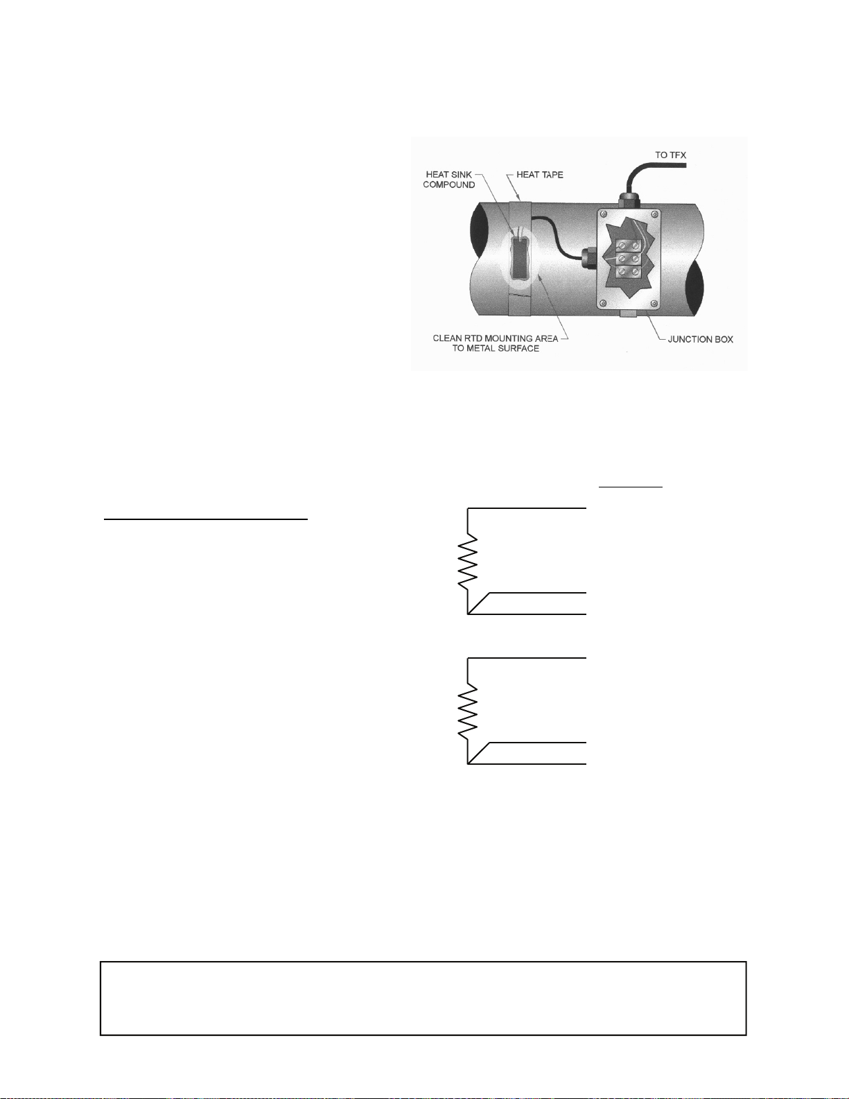
3. Place a small amount of heat sink
compound on the pipe in the RTD
installation location. See Figure 1.
Press the RTD firmly into the compound. Fasten the RTD to the pipe
with the included heater tape.
4. Route the RTD wires to an electrical
junction box in close proximity to the
installation location. Secure the RTD
wires such that they will not be pulled
on or abraded inadvertently. Replace the insulation on the pipe.
5. Route a cable from the electrical
junction box back to the FDT flow
meter. Connect the RTDs as illustrated in Figure 2. Note that the
SNS1 and DRV1 wires originate from
the same location on the RTD.
Figure 1
Transmitter Programming
FDT Module
REF1+2 & RTN
1. The RTDs included with the FDT heat
delivered flow meter have been fac-
RTD#1
tory calibrated and are marked with
an identification as to which terminal,
#1 or #2, the RTD has been cali-
SNS 1
DRV 1
brated. If recalibration of the RTDs is
required or RTDs other than those
REF1+2 & RTN
supplied with the FDT are being utilized, the UltraLink software utility will
be required. UltraLink can also be
used to configure all operating parameters of the heat flow instrument.
RTD#2
SNS 2
DRV 2
2. To properly measure heat delivery,
the specific heat capacity of the liquid
must be entered. When a liquid is
Figure 2
chosen from the FL TYPE list, a default specific heat will be loaded. This default value is displayed as SP HEAT in the
BASIC MENU. If the actual specific heat of the liquid is known or if it differs from
the default value, press the ENTER key and modify the value. Press the enter key
to save the value. See the values listed in Tables 1 and 2 for specific values. Enter
a value that is the mean of both pipes.
Description: Installation and Operation Manual Addendum
FDT Heat Flow Meter
Origin Date: 02/10/00 Revision: none Revision date: none Page 2 of 3
Page 78
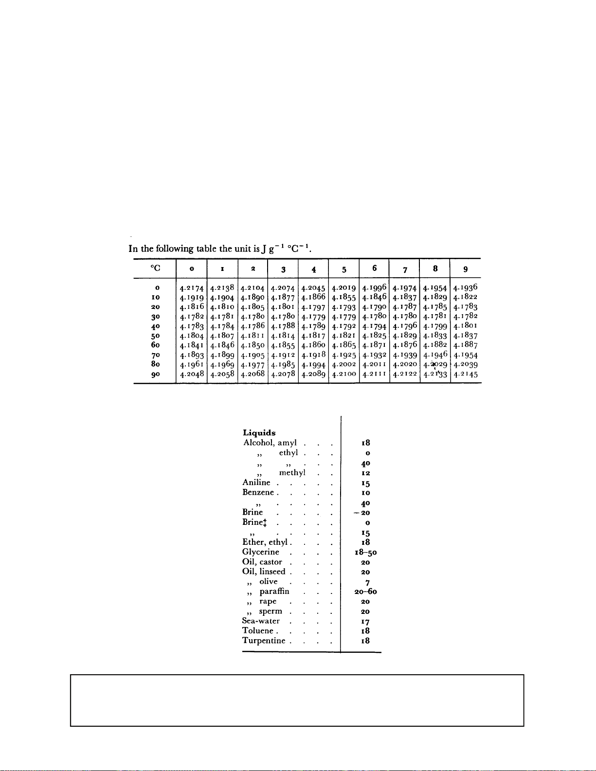
3. The RATE UNIT can be displayed as three different values; BTUs, CALs or Watts.
Select the proper unit from the RATE UNIT list. Select the appropriate RATE INTERVAL from the list (seconds, minutes, hours, days). Be aware that the instrument can only display values as large as 99,999,999.
4. Select an appropriate TOTALIZER UNIT from the list; BTU, CAL, Watt.
5. In the SER MENU three values can be displayed that may aid in troubleshooting
the heatflow instrument. In this menu, the temperature being read by RTD1 is indicated as TEMP1 (all values are degrees Celsius) , RTD2 as TEMP2 and the absolute difference as TEMPDIFF.
Table 1—Heat Capacity of Water
Table 2—Heat Capacity of Liquids
Description: Installation and Operation Manual Addendum
FDT Heat Flow Meter
Origin Date: 02/10/00 Revision: none Revision date: none Page 3 of 3
Page 79
Page 80
 Loading...