

Page 1
User’s Guide
Shop online at
omega.com
e-mail: [email protected]
For latest product manuals:
www.omegamanual.info
®
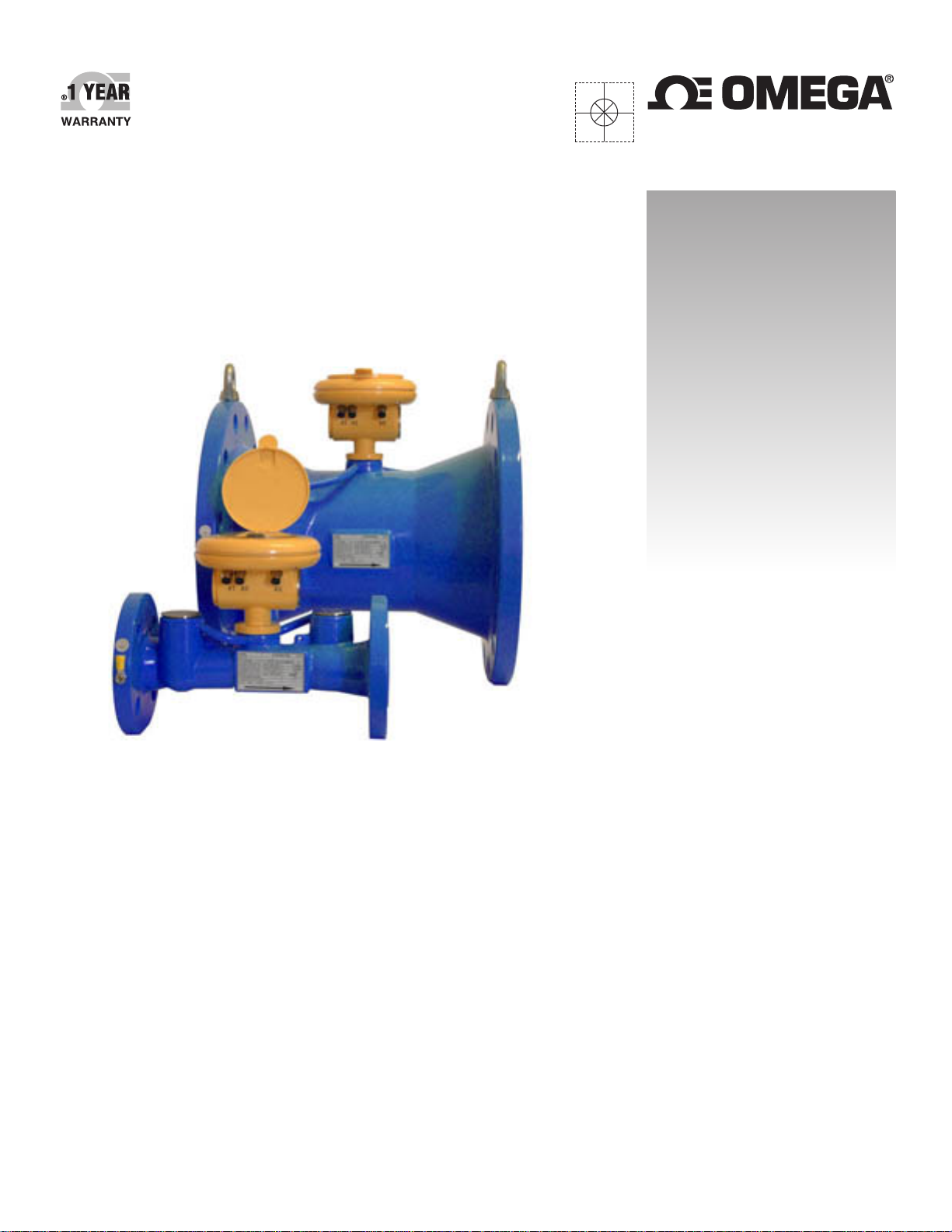
FDT500 Series
Ultrasonic Flow Meters
Page 2

omega.com [email protected]
Servicing North America:
U.S.A.: Omega Engineering, Inc., One Omega Drive, P.O. Box 4047
Stamford, CT 06907-0047 USA
Toll-Free: 1-800-826-6342 (USA & Canada only)
Customer Service: 1-800-622-2378 (USA & Canada only)
Engineering Service: 1-800-872-9436 (USA & Canada only)
Tel: (203) 359-1660 Fax: (203) 359-7700
e-mail: [email protected]
For Other Locations Visit omega.com/worldwide
The information contained in this document is believed to be correct, but OMEGA accepts no liability for any errors it contains, and reserves
the right to alter specifications without notice.
WARNING: These products are not designed for use in, and should not be used for, human applications.
Page 3

Project design, meter installation and service manual
Battery-powered ultrasonic water meters
of the FDT500 series
Page 3 of 28
Contents
1. APPLICATION ........................................................................................................................................................ 4
2. MEASUREMENT PRINCIPLE ................................................................................................................................ 4
3. TECHNICAL DESCRIPTION .................................................................................................................................. 4
3.1. Meter version .................................................................................................................................................................... 4
3.1.1. Meter sensors .......................................................................................................................................................... 4
3.2. Meter design ..................................................................................................................................................................... 5
3.2.1. Dimensional drawing ................................................................................................................................................ 5
3.2.2. Electronic unit .......................................................................................................................................................... 6
3.2.3. Ultrasonic sensor ..................................................................................................................................................... 7
3.2.4. Sensor terminal board (the remote meter design version) ....................................................................................... 7
4. TECHNICAL PARAMETERS .................................................................................................................................. 8
4.1 Sensor dimensions and flow-rate ranges ...................................................................................................................... 10
5. PROJECT DESIGN AND METER INSTALLATION ............................................................................................. 10
5.1. Project design of systems including ultrasonic water meters .......................................................................................... 10
5.1.1. Straight piping sections before and after the sensor .............................................................................................. 11
5.1.2. Elimination of the effect of pumps in the piping ...................................................................................................... 11
5.1.3. Piping stacks .......................................................................................................................................................... 11
5.1.4. Flooding of the piping cross-section ....................................................................................................................... 12
5.1.5. Mechanical connections ......................................................................................................................................... 13
5.1.6. Electrical connections ............................................................................................................................................ 14
5.1.7. Sealed meters ........................................................................................................................................................ 15
5.2. Operational start ............................................................................................................................................................. 15
6. OPERATION ......................................................................................................................................................... 15
6.1. Reading of the measured data from the display ............................................................................................................. 15
6.2. Electric outputs ............................................................................................................................................................... 17
6.2.1. Pulse outputs ......................................................................................................................................................... 17
6.2.2. Current output (-A, optional) associated with flow rate or fluid pressure quantities (-PS, optional) ........................ 19
6.2.3. Binary flow-direction indication ............................................................................................................................... 21
6.3. Power source ................................................................................................................................................................. 22
6.3.1. Battery lifetime and replacement ............................................................................................................................ 22
6.3.2. Electronic unit powered from current loop .............................................................................................................. 23
6.4. Communication interface ................................................................................................................................................ 23
6.4.1. Communication via optical probe (-OPT, optional) ................................................................................................. 24
6.4.2. Communication via RS232 cable ........................................................................................................................... 25
6.5. Identification of errors listed in the archive ..................................................................................................................... 26
7. CALIBRATION ...................................................................................................................................................... 26
Page 4

Project design, meter installation and service manual
Battery-powered ultrasonic water meters
of the FDT500 series
Page 4 of 28
1. APPLICATION
The battery powered ultrasonic FDT500 series water meter is designed for industrial and commercial applications that
require measurements of instantaneous flow rate, pressure (optional) and accumulated flow total. The meter design
and parameters meet the requirements of standard EN 14154. The technical capabilities and parameters of the
FDT500 water meters make them an ideal solution for not only water consumption measurement but also for water
leakage and water-supply network condition monitoring with optional wireless data transfer features.
The standard compact meter version is intended for operation in environments where the
meter will not be immersed.
2. MEASUREMENT PRINCIPLE
The meter utilises the "transit-time" impulse measurement method where the flow rate information is derived from the
difference between the measured transit times of ultrasonic signals travelling between ultrasonic probes in and
against the flow direction of the measured fluid.
3. TECHNICAL DESCRIPTION
3.1. Meter version
Battery-powered ultrasonic water meters of the FDT500 series are manufactured in standard design:
- Single beam, Compact version, display, button, power supply Li-battery 3.6V, T
ANSI 150 psi, pulse output with 5 m of cable, current output 4-20mA (-A, optional), material of measured part casting from cast iron, covering by powder colour KOMAXIT, protection IP67, calibration in 3 points, CE mark
= 50°C, flanges according to
max
3.1.1. Meter sensors
The water meter measuring sensor is designed for operation under conditions typical for conventional mechanical
water meters regarding the scope of measured values including the fluid pressure (-PS, optional) (not exceeding 16
bar).
3.1.2. Electronic unit
All water meters work in combination with an electronic unit of a unified design.
The standard electronics unit version includes the following functions:
• Measurement and display of instantaneous flow rate values in one flow direction [m3/h, gal/min];
• Display of the total volume passed through the meter sensor in one flow direction [m3 , 103 gal];
• Flow rate information communicated via a passive insulated pulse output.
Electronic unit with additional functions makes possible/includes:
• Measurement and display of instantaneous flow rate and flow volume data in both flow directions with graphic
indication of the actual flow direction on the meter display;
• Measurement and display of instantaneous fluid pressure values (-PS, optional);
• Passive current output 4-20mA (-A, optional) corresponding to the instantaneous flow rate and fluid pressure
values (-PS, optional) (only one parameter at a time);
• Fluid flow direction indication via:
o binary output for a current loop 4-20mA (in cases of bi-directional flow rate measurement )
• Two-wire power supply to the electronic unit using a current loop 4-20mA;
• Mutually independent measured data storage in periods one minute to one year;
• Measured and stored data reading using optically insulated interface USB or RS232 line;
Available for the electronic unit with additional functions are the associated accessories such as interconnection
cables, optical probe or software programs.
Comment: Application of additional electronic unit functions shortens the effective
battery life.
Page 5
Type
DN
Type of sensor
ø D [inch
] /
[mm]
Project design, meter installation and service manual
Battery-powered ultrasonic water meters
of the FDT500 series
Page 5 of 28
3.2. Meter design
Taking into account the meter sensor design, the meter series consists of the following meter types:
Water meter
FDT500
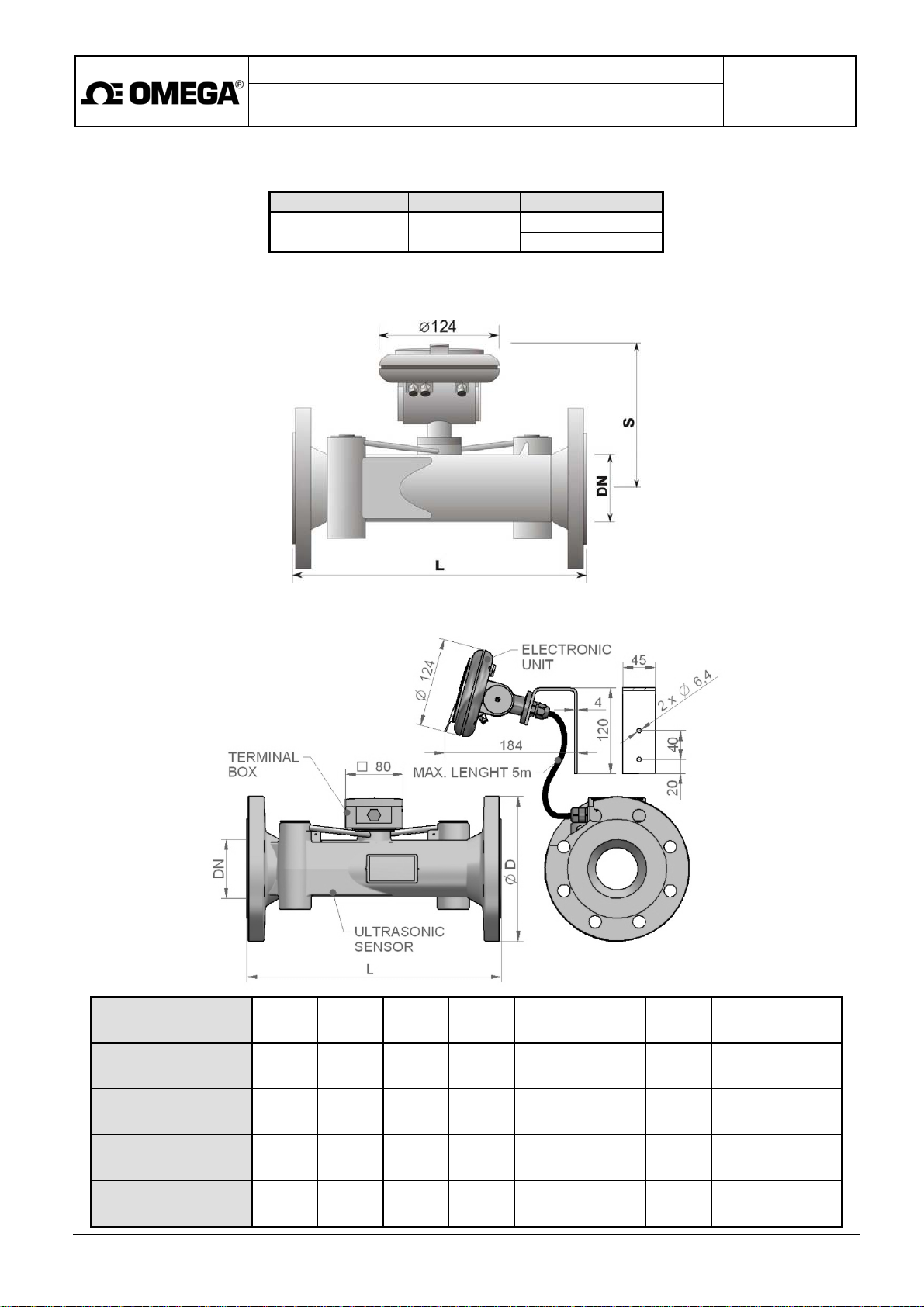
3.2.1. Dimensional drawing
FDT500
FDT500-R
1 1/4" to 8"
(32 to 200)
Standard
-PS (Optional)
DN [inch] / [mm]
L [inch] / [mm]
S [inch] / [mm]
Weight [lb] / [kg]
for ANSI 150 lb
1 1/4"
32
10.24 /
260
5.51 /
140
1 1/2"
40
11.81 /
300
5.71 /
145
2"
50
11.81 /
300
5.91 /
150
15.4 / 7 17.6 / 8 22 /
10
4.62 /
117.3
5 /
127
6 /
152.4
2 1/2"
65
11.81 /
300
6.10 /
155
24.3 /
11
7 /
177.8
3"
80
13.8 /
350
6.3 /
160
33.1 /
15
7.5 /
190.5
4"
100
13.8 /
350
6.5 /
165
38.6 /
17.5
9 /
228.6
5"
125
13.8 /
350
7.09 /
180
49.6 /
22.5
10 /
254
6"
150
13.8 /
350
7.48 /
190
57.3 /
26
11 /
279.4
8"
200
13.8 /
350
8.07 /
205
80.5 /
36.5
13.5 /
342.9
Page 6
Project design, meter installation and service manual
Battery-powered ultrasonic water meters
of the FDT500 series
Page 6 of 28
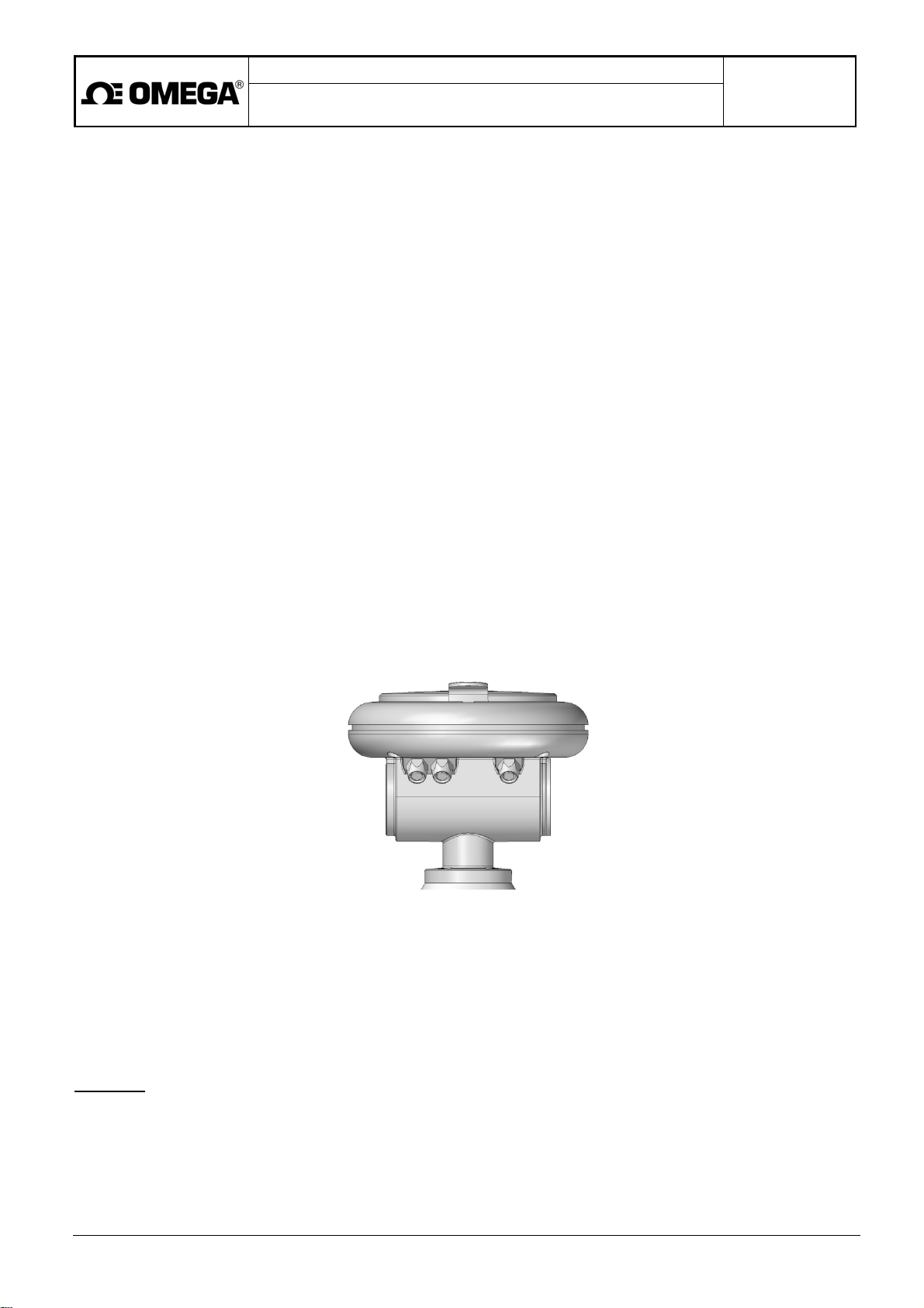
3.2.2. Electronic unit
The electronic circuits and the meter battery are accommodated in an aluminium box with a plastic cap and a lift-off
protective cover. The box is further provided with a pressure equaliser preventing air humidity condensation inside the
electronic unit box.
The external box surface is painted with a powder paint of hue RAL1017 (saffron yellow).
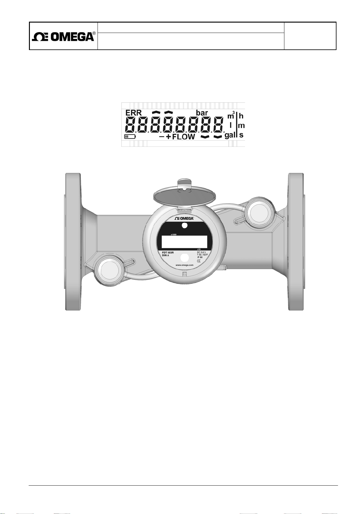
Located under the protective cover are the meter rating plate, control push-button and a recession to accommodate
the optical probe. A window in the plastic cap facilitates view of the meter display showing the measured values and
the respective physical units:
• Instantaneous flow rate;
• Total volume passed through the meter in the + direction;
• Instantaneous fluid pressure (-PS, optional);
• Total volume passed through the meter in the - direction;
• Check sum.
The displayed quantity can be selected by repeated pressing of the control pushbutton (depress for 1s and leave the
pushbutton free for 1s before next depression).
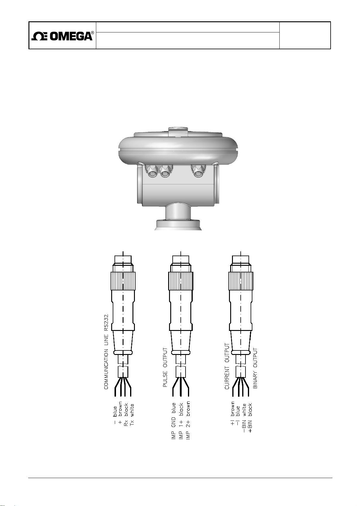
In the case of the standard electronics unit version, only connector X2 (pulse outputs) is installed; the openings for
connectors X1 and X3 are sealed. In the case of electronic unit with additional functions, all three connectors (X1, X2
and X3) can be active. When installed, each connector is provided with a water-proof cap sealed with an O-ring.
Connector specifications:
• X1 - communication line RS232 (a 4-pole connector);
• X2 - two pulse outputs (a 3-pole connector);
• X3 - one current and one binary output (a 4-pole connector).
The interconnection of individual outputs is described in Section 6.2., Electric outputs.
Upon a customer's request, supplied with the meter can be the necessary connecting cables meeting the IP68
standards.
Cable specifications:
Connector X1: a 4-pole plug, 5m cable and a 9-pin Canon connector;
Connector X2: a 3-pole plug, 5m cable and free wires for connection to the master control system;
Connector X3: a 4-pole plug, 5m cable and free wires for connection to the master control system.
CAUTION: Prior to putting the meter in operation, make sure that all connectors are tightly screwed on and the openings
of unused connected properly sealed. The electronic unit shall not be exposed to direct sunlight.
Page 7
Project design, meter installation and service manual
Battery-powered ultrasonic water meters
of the FDT500 series
Page 7 of 28
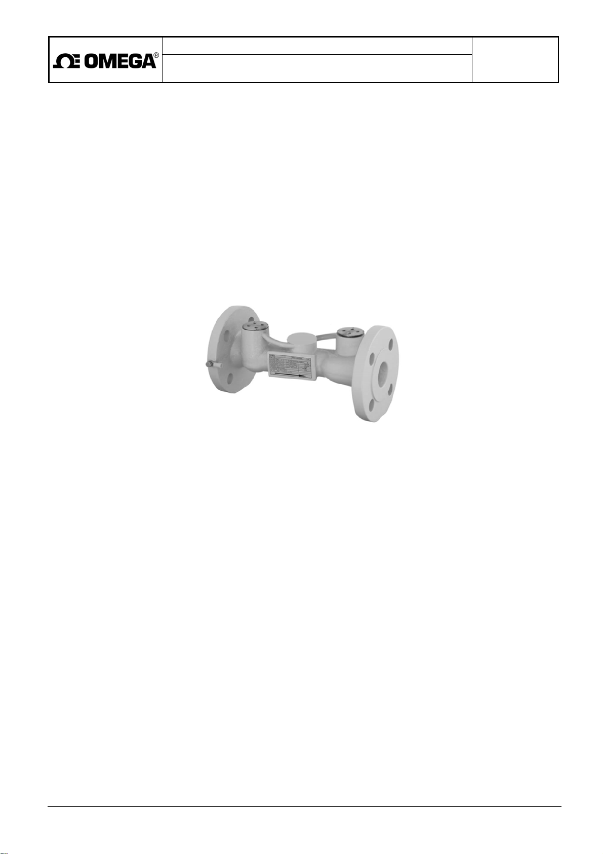
3.2.3. Ultrasonic sensor
The ultrasonic sensor used with water meters of type designation UC 6.X is embedded in a malleable iron casting.
Each sensor includes two ultrasonic probes (single beam sensor version). The probe bodies are made of stainless
steel.
Water meter sensors may also include pressure detectors.
Unless required otherwise, the sensors are provided with flanges meeting the ANSI 150 psi specifications. Other
types of flange such as according to standards EN 1092-1, JIS, AS and others may be used on agreement with the
sensor manufacturer. The rating plate attached to the sensor body includes information and data in reference to
standard EN 14154-1+A1, clause 6.
The sensors are painted with powder epoxy-polyester paint of hue RAL 5017 (blue). The sensors used with water
meters UC6.X may also be painted with polyamide RILSAN 7443MAC paint (blue).
UC 6.X
3.2.4. Sensor terminal board (the remote meter design version)
In cases of remote design of the FDT500-R water meters, attached to the sensor body is an aluminium box
containing the sensor terminal board.
The water meter is supplied complete with a cable of length 5m meeting the protection class IP68 requirements
intended to provide connection between the electronic unit and meter sensor.
The terminal box includes an M12 grommet and a lid with a sealing O-ring.
To ensure meeting the requirements of the specified protection class (IP68), the terminal box interior is sealed
with waterproof resin.
Page 8
Meter pressure class
Display unit
Operational ambient
Storage te
mperature
Protect
ion
imp
Project design, meter installation and service manual
Battery-powered ultrasonic water meters
of the FDT500 series
Page 8 of 28
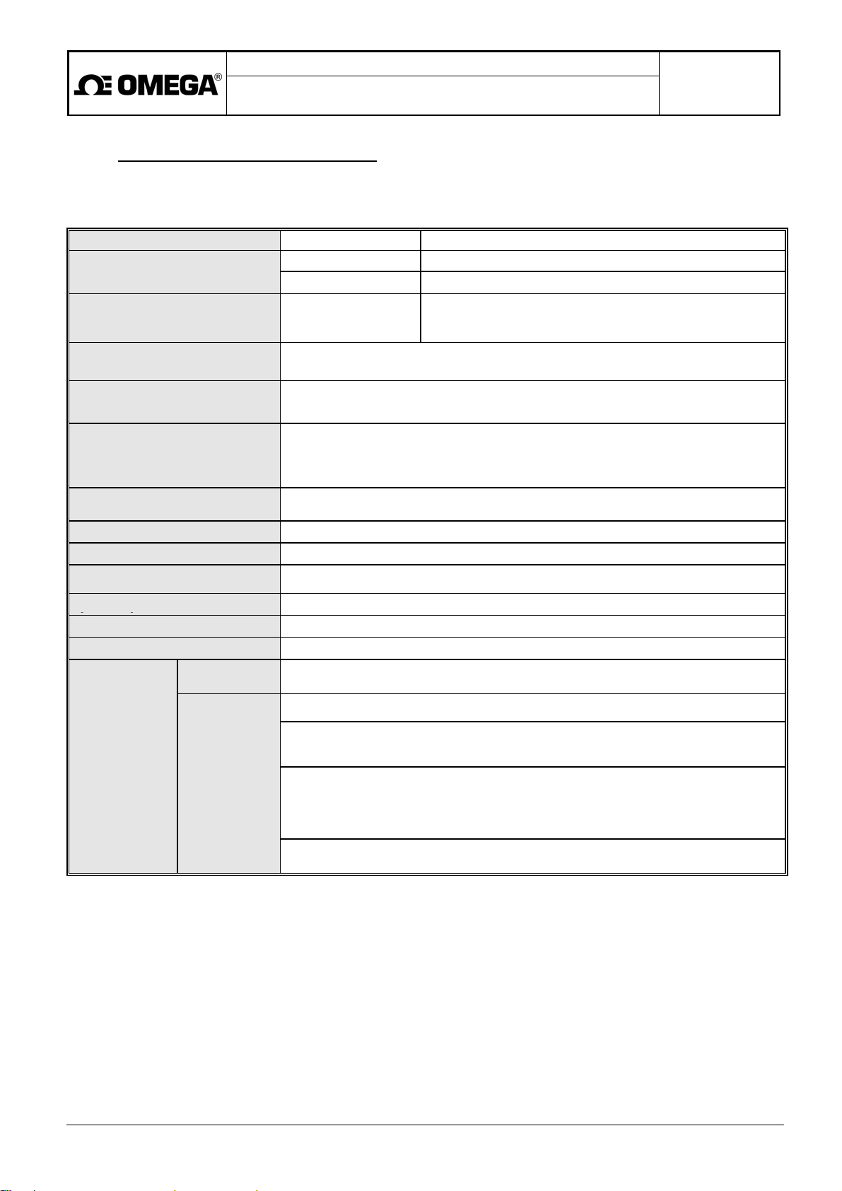
4. TECHNICAL PARAMETERS
The symbols and abbreviations used in the following technical specifications comply with the provisions of
standard EN 14154-1+A2, part 3, Terms and definitions.
Temperature class
Flow profile sensitivity class
Water meters
Compact version T50 (water meters FDT500)
Remote version T90 (water meters FDT500-R)
Single beam sensor
MAP 16 single beam FDT500 (DN 1 1/4" to 8" / 32 - 200)
Minimum Upstream and Downstream pipe requirements
DN10 and DN5
DN10 with straightener, D5 (for DN 1 1/4" / 32)
Pressure loss class
Climatic and mechanical
environment
Accuracy
∆P 25 (the highest pressure class 0,25 bar)
Class B (static meters installed in a building) – type approved meters
Class B, C (static meters installed outside) – non-certified meters
Referential condition in compliance EN 14154-3+A2
± 5% for flow Q1 ≤ Q < Q2
± 3% for flow Q2 ≤ Q ≤ Q4
± 0,5% FSO for pressure 0 – 16 bar relative
Electromagnetic environment
Measurement cycle period
E1, E2 (environment of flats, shops and light industry, industrial environment)
1 s
Single-line 8-digits LC display
Power supply
Lithium battery 3,6 V/19 Ah, live time min. 8 years in standard version
23°F to 131°F / -5°C to +55°C (protection against direct sunshine)
14°F to 158°F / -10°C to +70°C (by relative humidity max. 70%)
IP67
Outputs and
functions
Standard
Non-standard
One direction measurement of flow with 1 passive pulse output
1x open collector NPN: U = 3 to 30 V, I = 0.002 to 10 mA, t
= 30 ms
Passive current output 4 to 20mA (-A, optional), U = 10 to 24 V (flow or pressure)
Each
passive output
Bidirectional measurement of flow with 2 passive pulse outputs
2x open collector NPN: U = 3 to 30 V, I = 0.002 to 10 mA, t
= 30 ms
imp
must be
powered from
individual
galvanic
insulated
remote source
Bidirectional measurement of flow with passive current output 4 to 20mA (-A, optional),
U = 10 to 24 V
with indication of flow direction of flow by static passive output - transistor NMOS-FET:
U = 3 to 30 V, I = 0,002 to 10 mA
Optical interface USB, RS232, RS232+USB driver
Measurement of pressure (non for remote version and for temperature over 120°C)
The value of minimum flow rate at which the meter starts to indicate and measure the flow data (Q
) has been
NEC
set at the manufacturing company at 20 mm/s. Upon the customer's request, this setting can be modified within
the range Q
= 0,1 to 25% Q4.
NEC
Page 9
Project design, meter installation and service manual
Battery-powered ultrasonic water meters
of the FDT500 series
Page 9 of 28
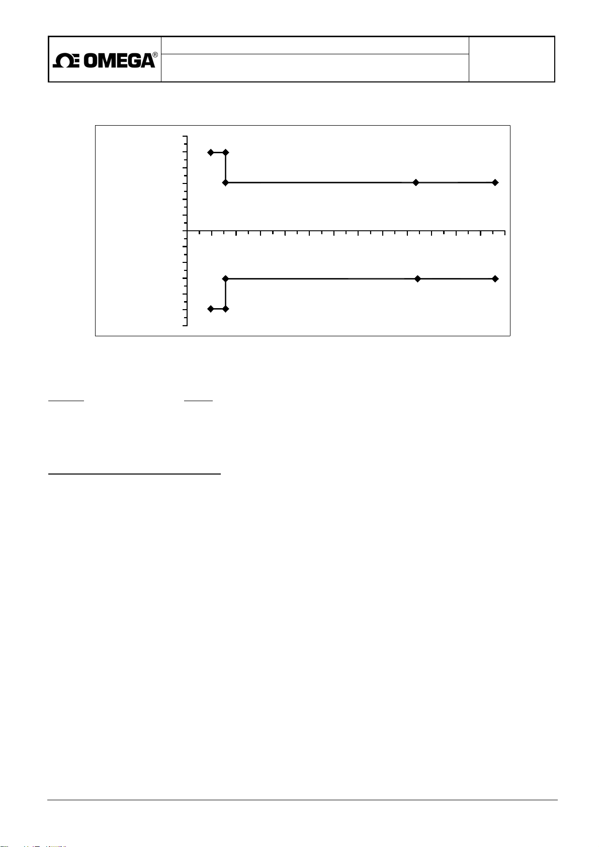
Water meter precision rating in accordance with standard EN 14154
for temperature classes T50 and T90
6
5
4
3
2
1
0
-1
-2
RELATIVE ERROR [%]
-3
-4
-5
-6
01 02
03 04
FLOW
According to ČSN EN 14154, it holds:
Q4
Q3 Q1
The flow rate values Q1,Q3 and Q4 related to individual design versions and meter dimensions are shown in
Section 4.1.
= 1.25
Q2
= 1.6
Meter capabilities and functions:
• Measurements in one or both fluid flow directions (with flow velocity not exceeding 10 m/s);
• Measurements of fluid volumes passed through the meter sensor in both flow directions;
• Measurement of relative pressure of the flowing fluid;
• Storage of data concerning:
o flow rate,
o fluid volume passed through the meter in one direction (+),
o fluid volume passed through the meter in the other direction (-),
o pressure,
o real time of commencement of failure condition,
o real time of termination of failure condition,
o diagnosed failure conditions,
o watch dog (WD) actions;
• Firmware consistency test - check sum CRC32 once every 24 hours;
• LC display test consisting of lighting-up all display segments.
Page 10
Overload flow Q
Permanent flow Q
[GPM]
Minimum flow Q
[GPM]
Constant of pulse output K
Range of measurement Q
Project design, meter installation and service manual
Battery-powered ultrasonic water meters
of the FDT500 series
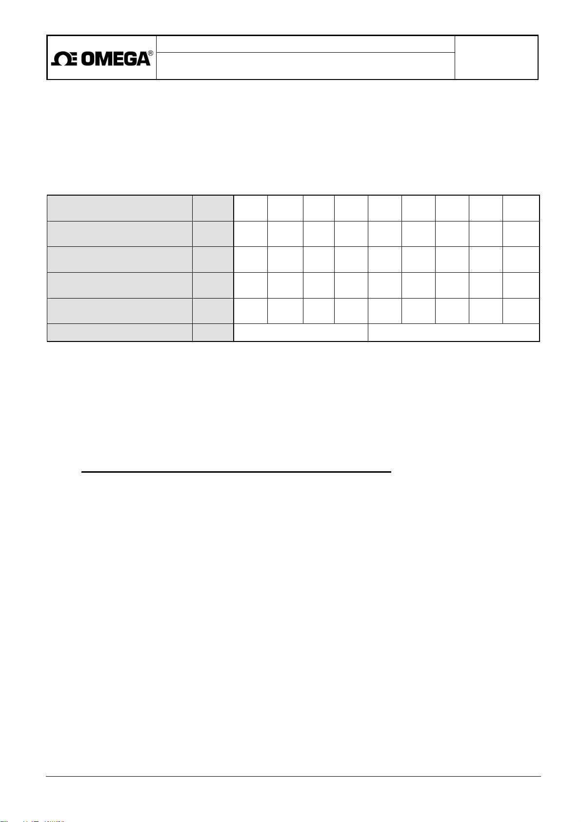
4.1 Sensor dimensions and flow-rate ranges
FDT500 (water meter, single beam, compact version)
FDT500-R (water meter, single beam, remote version)
Nominal diameter DN
4
3
1
i
3/Q1
[inch]
[mm]
[GPM]
[m3/h]
[m3/h]
[m3/h]
[G/imp]
[l/imp]
1 1/4"
32
55.04
12.5
44.03
10
0.176
0.04
2.6
10
1 1/2"
40
88.06
20
70.45
16
0.282
0.064
2.6
10
2"
50
137.6
31.25
110.1
25
0.440
0.1
6.6
25
1 1/2"
220.1
176.1
0.704
250 315
65
50
40
0.16
13.2
50
3"
80
346.7
78.75
277.4
63
0.881
0.200
13.2
50
4"
100
550.3
125
440.3
100
1.396
0.317
26.4
100
Page 10 of 28
5"
125
880.6
200
704.5
160
2.237
0.508
26.4
100
6"
150
1376
312.5
1101
250
3.496
0.794
26.4
100
8"
200*
2201
500
1761
400
5.592
1.270
66
250
*
With these dimensions, the data shown on display are one tenth of the actual values (see Section 6.1.)
5. PROJECT DESIGN AND METER INSTALLATION
5.1. Project design of systems including ultrasonic water meters
In project designing and installation of ultrasonic water meters of the FDT500 series, the general rules regarding
placement of water meters in piping as outlined in standard ČSN EN 14 154 need be observed.
The following text includes specific requirements concerning the minimum lengths of the straight piping sections at the
sensor input and output with respect to various nearby-located flow-disturbing elements and measures to ensure full
flooding of the sensor space.
Page 11
Project design, meter installation and service manual
Battery-powered ultrasonic water meters
of the FDT500 series
Page 11 of 28
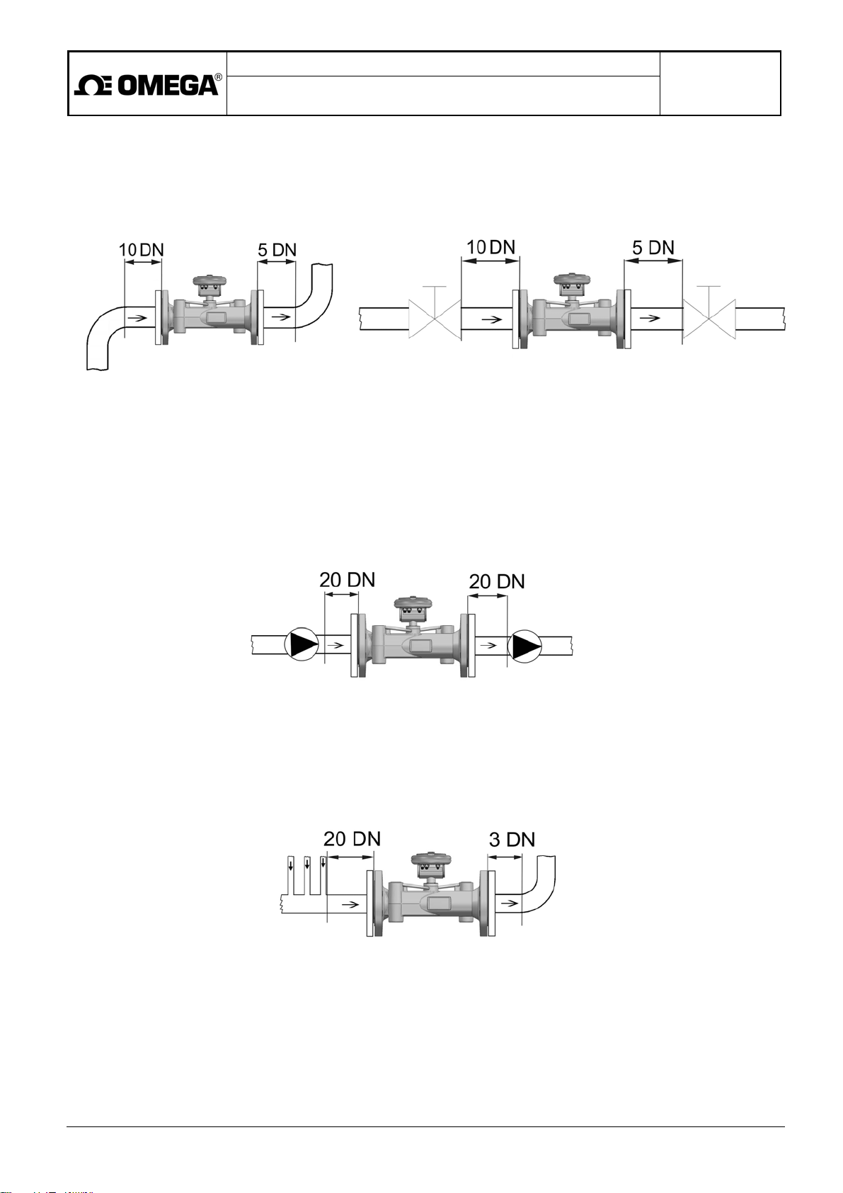
5.1.1. Straight piping sections before and after the sensor
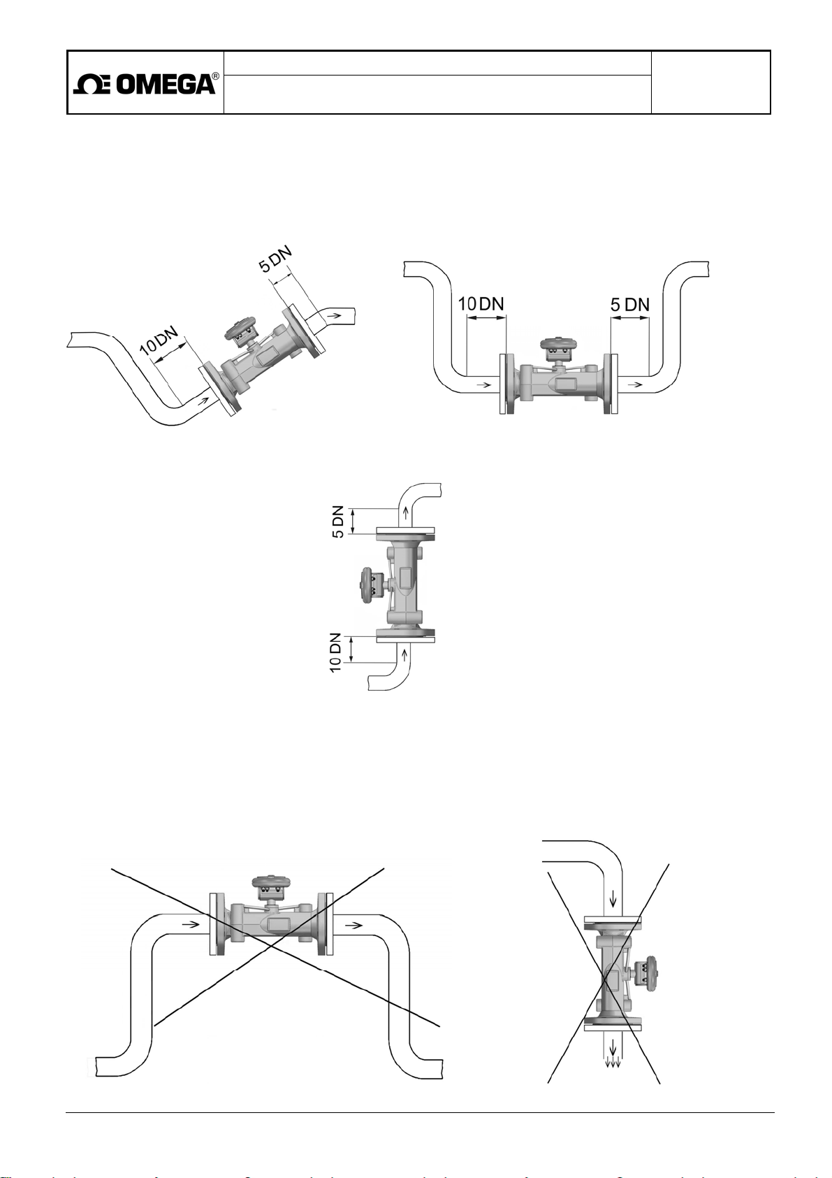
For a single-beam sensor, the minimum straight upstream and downstream pipe requirements are: DN10, DN5.
5.1.2. Elimination of the effect of pumps in the piping
The nearest pump in the piping shall be located at least 20 DN away from the meter sensor.
To eliminate the effects of cavitation and gas release from the measured fluid, it is recommended to place the
pump at the input side of the sensor. The cavitation effects can also be effectively suppressed by sufficiently high
pressure in the piping system.
5.1.3. Piping stacks
The nearest stack in the piping system at the sensor input side shall be at least 20 DN away.
Page 12
Project design, meter installation and service manual
Battery-powered ultrasonic water meters
of the FDT500 series
Page 12 of 28
5.1.4. Flooding of the piping cross-section
The meter sensor shall always be fully flooded with the measured fluid (water).
In cases where complete flooding of the whole piping system cannot be ensured at all times, the sensor placement
shall be such that this condition is always met at the piping section concerned.
Preferred placement of single-beam sensors in the fluid piping
If the meter sensor is placed in a vertical piping section, the flow direction shall be upwards.
Single-beam sensor
It is not recommended to place the meter sensor at the highest piping section or, in cases of the sensor placement in
a vertical piping section, with the fluid flow direction downwards, in particular if a discharge opening is anywhere near
at the sensor output side. Observance of this rule will prevent measurement errors due to increased air bubble
concentration inside the sensor space.
Examples of incorrect sensor placement
Page 13
Project design, meter installation and service manual
Battery-powered ultrasonic water meters
of the FDT500 series
Page 13 of 28
WARNING! In cases of external placement, the electronic unit shall be protected against direct sunlight.
However, the unit shall not be placed in an enclosed box.
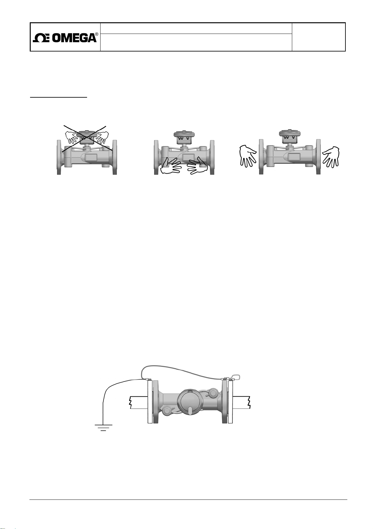
Meter handling rules
When lifting the meter, never hold it by any part of the electronic unit, but always by the sensor flanges or sensor
body.
☺ ☺
Meter storage
During storage and transport, the meter shall be protected against excessive mechanical shocks and vibrations.
The best protection is provided by the original packaging.
Permitted storage temperature range: – 10 to +70°C at relative humidity of the air not exceeding 70%.
Long-term exposure of the meter to direct sunlight shall be avoided.
5.1.5. Mechanical connections
The ultrasonic sensor shall be installed in the piping using suitable counter-flanges meeting the requirements of
standard ČSN EN 1092-1 (or, upon the customer's request, ANSI, JIS or AS).
During the sensor installation, make sure that:
• The arrow on the sensor body points at the fluid flow direction;
• The inner piping and seal diameters correspond to that of the water meter sensor;
• The sealing elements are properly placed between the flanges;
• The piping supports minimise the mechanical stress acting on the sensor (vibration, tension, bend etc.).
The sensor needs be properly grounded. To ensure that, use the green and yellow earthing conductor of
minimum cross section 4mm2 to connect the earthing bolt on the sensor flange to the piping flanges and the ground
potential at the measurement location.
Page 14
Project design, meter installation and service manual
Battery-powered ultrasonic water meters
of the FDT500 series
Page 14 of 28
5.1.6. Electrical connections
The only active connector on FDT500 water meters of standard design is connector X2 - pulse output. The openings
provided for connectors X1 and X3 are sealed with metal lids meeting the requirements of protection class IP68.
In cases of meter with additional functions all three connectors (X1, X2 and X3) may be installed. Should any of the
outputs be unused, the respective connector shall be sealed with a screw-on cover M8x1 meeting the requirements of
IP68.
To avoid electromagnetic interference, the connecting cables to the electronic unit shall be laid at least 25cm away
from the power cables of any other equipment.
X1 X2 X3
X1 X2 X3
Page 15

Project design, meter installation and service manual
Battery-powered ultrasonic water meters
of the FDT500 series
Page 15 of 28
5.1.7. Sealed meters
The FDT500 water meters are supplied with parameters set according to the customer requirements.
To prevent unauthorised interference with the meter setting, important meter parts are provided with stick-on
assembly seals located on/at:
Electronic unit
2x bolts at the bottom of the electronic unit box
1x connection between the electronic unit box and the meter sensor
1x connection between the battery lid and the electronic unit box
Sensor
1x connection between the meter rating plate and the sensor body
2x connection between the ultrasonic probe covers and the sensor body
5.2. Operational start
The meters are supplied calibrated and in a fully operational condition. The correct meter function is indicated by the
vertical slash sign flashing with the measuring frequency (1Hz) and the display of the ERR symbol on the LC display.
Upon the meter installation in the piping, its flooding and bleeding, the ERR symbol will disappear and the meter will
start its normal measuring functions. Use the control pushbutton to check switching between the measured quantities
shown on the display.
6. OPERATION
6.1. Reading of the measured data from the display
The display can show the values of up to four measured quantities and a check sum. The selection of the desired
quantity is done by means of the control pushbutton (depress for 1s and wait for another second). In cases where
the meter does not include any additional measuring functions, the display will show zero values for the missing
measured quantities.
The correct meter operation is indicated by a vertical slash sigh blinking with the measurement frequency (1Hz).
The need to replace the source battery will be indicated by a lighted battery sign.
In cases of error, the ERR sign will appear on the display (see Section 6.5. below).
With water meters of DN 8" / 200 dimension, the sign at the bottom right-hand corner of the display indicates that
the real values of instantaneous flow rate and of the total volume passed through the meter sensor are 10 times as
great as the respective values shown on the display. The same applies to the stored flow rate and fluid volume data
that are 10 times smaller than the actual/real values.
The standard meter version
Single-direction fluid flow measurements with the following data appearing on the meter display:
• Instantaneous flow rate with a + sign indicating the correct fluid flow direction (in agreement with the arrow
sign on the meter sensor) and the word FLOW displayed; selectable measurement units [m3/h, l/s, gal/min];
• The total volume passed through the meter sensor with a + sign indicating the correct fluid flow directions;
The meter version including additional functions
Fluid flow measurements in both directions with the following data appearing on the meter display:
Fluid pressure measurements (-PS, optional):
selectable measurement units [m3, 103 gal].
• Instantaneous flow rate with + or - sign and the word FLOW displayed; selectable measurement units
[m3/h, l/s, gal/min];
• The total volume passed through the meter sensor in ether flow direction with + or - sign displayed, selectable
measurement units [m3, 103 gal].
• Fluid pressure value in [bar].
Page 16
Project design, meter installation and service manual
Battery-powered ultrasonic water meters
of the FDT500 series
Page 16 of 28
Display test
To test the meter display, keep the control pushbutton depressed for 5s whereby all display segments and signs
should light up. Upon releasing the control pushbutton, the display will return to the instantaneous flow rate value
display mode.
Measured data processing algorithms
• Instantaneous flow rate – single-beam sensor
The data shown on the display as well as those contained in the meter outputs are the product of a statistical
processing of the measured data (statistic filter).
The total volume passed through the meter sensor
The fluid volume data are displayed with the precision of three valid digits after the decimal point of the selected
measurement unit [m3, 103 gal] up to the maximum value 99999.999.
Upon exceeding this limit value, the decimal point will shift to the left so that the maximum total volume indicated on
the meter is 999999.99 and, eventually, 9999999.9 [m3, 103 gal].
Taking into account practical measurement conditions and the meter lifetime, any further increase of the meter
measurement range is considered unnecessary.
Page 17
Project design, meter installation and service manual
Battery-powered ultrasonic water meters
of the FDT500 series
Page 17 of 28
6.2. Electric outputs
The electric outputs are accessible via connectors X2 and X3.
6.2.1. Pulse outputs
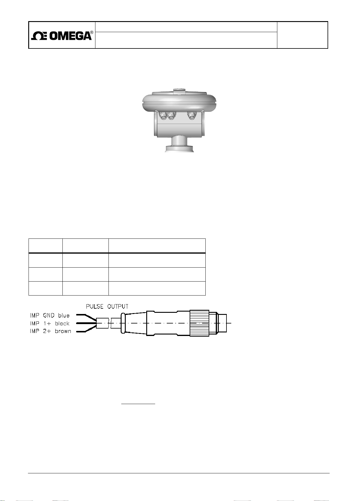
The pulse outputs for both flow directions (+/- FLOW) are connected to the socket of a 3-pole connector (X2). These
are passive and insulated outputs.
Each passive output shall be powered from an independent insulated power source.
As optional accessory, the meter manufacturer offers to meters with pulse outputs a 5m cable terminated on one end
with a matching 3-pole plug and free wires on the other cable end for interconnection to a master control system.
Interconnection cable for connector X2
Indication
IMP1 + black
IMP2 + brown
Color of wire Function
Flow in direction of arrow on
a sensor
Flow against direction of arrow on
a sensor
IMP GND blue Common wire
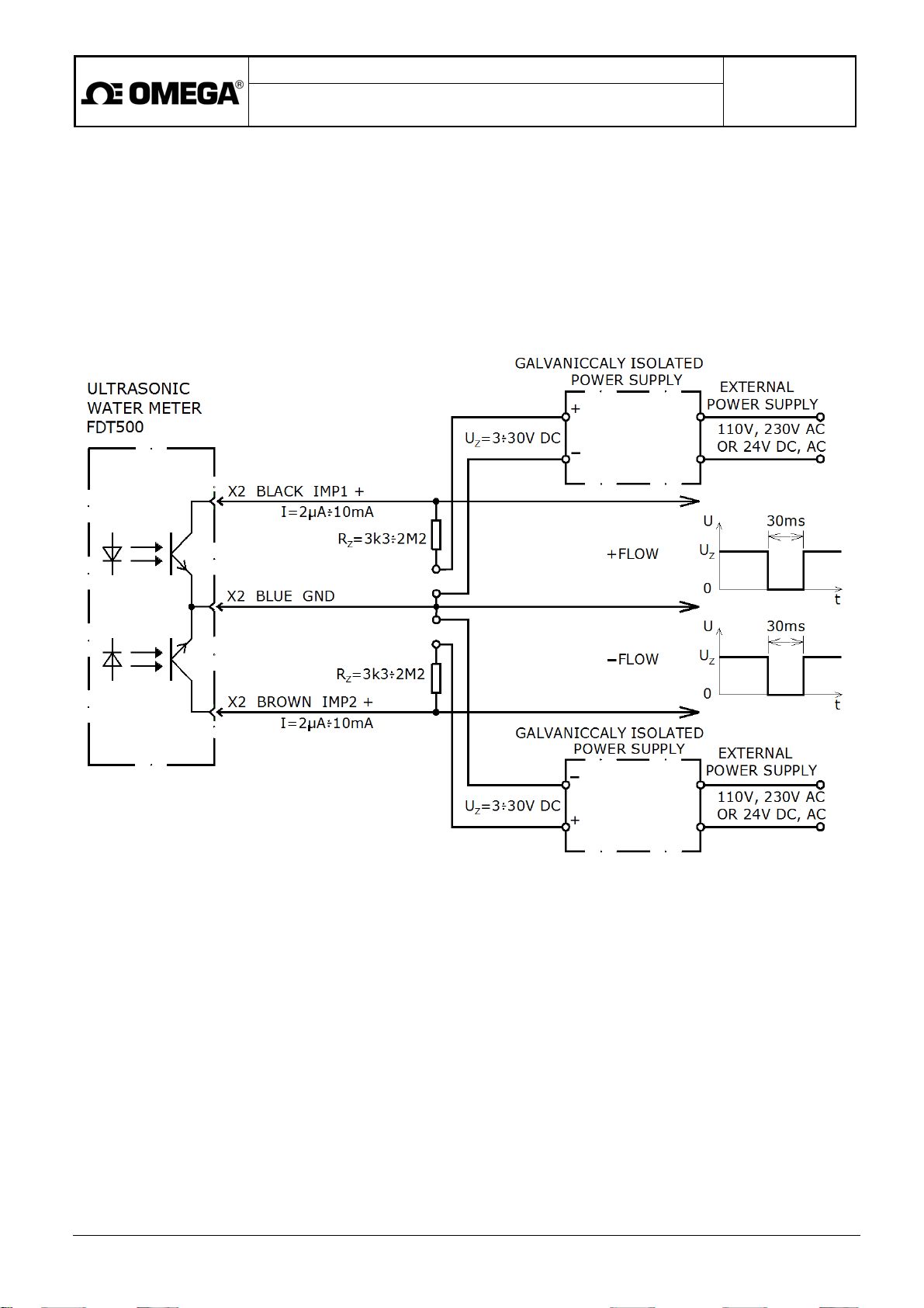
The pulse output is insulated by means of an optocoupler with an open-collector NPN transistor:
• External power source voltage Uz = 3V to 30V
• Output current loading 2µA to 10mA
Load resistance value:
Rz [
Ω]
=
Uz [V]
I [A]
Maximum impulse frequency: 1 Hz
Impulse width: 30 ms (fixed)
Page 18
Project design, meter installation and service manual
Battery-powered ultrasonic water meters
of the FDT500 series
Page 18 of 28
The maximum impulse frequency imposes a limit on the maximum flow rate. The flow rate ranges for individual
sensor dimensions are given in Section 3.3.
In cases of short-term increase of the flow-rate values above the permitted maximum (Q4), an ERR message on the
display will indicate this condition and the corresponding information will be recorded in the data archive. The impulse
frequency will not increase but the impulses that have not appeared at the outputs will be saved and sent later when
the flow rate values drop below the maximum value again. Thus these immediately unsent impulses will not be lost
and the master system will receive the correct number of impulses corresponding to the flow volume passed through
the measuring point. However, in cases of long-term excess of the maximum flow rate value, the processor memory
may overflow whereby some of the impulses will be lost.
Pulse output connection diagram
Page 19
Project design, meter installation and service manual
Battery-powered ultrasonic water meters
of the FDT500 series
Page 19 of 28
6.2.2. Current output (-A, optional) associated with flow rate or fluid pressure
quantities (-PS, optional)
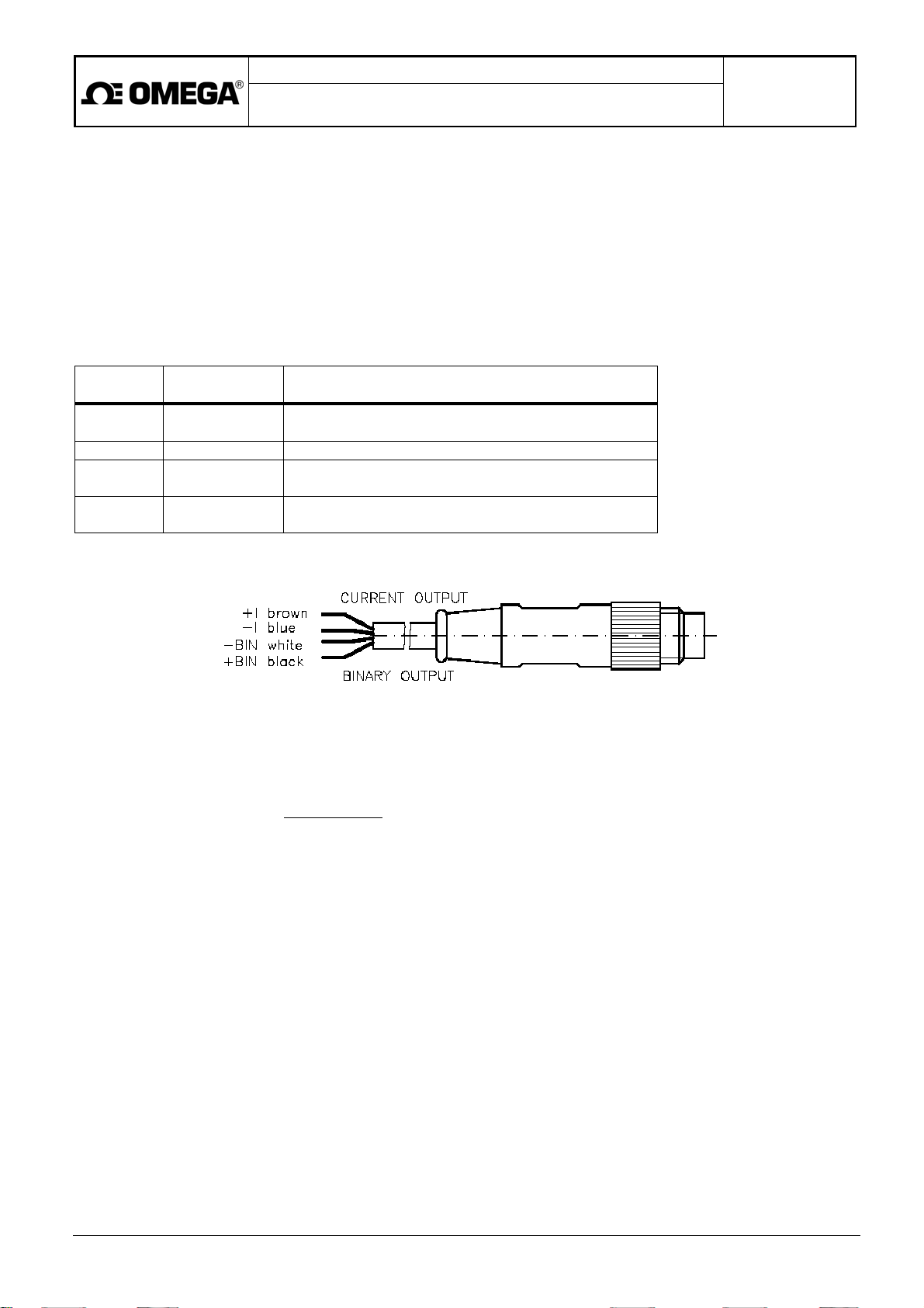
The current output 4 to 20mA (-A, optional) is connected to the socket of a 4-pole connector (X3). It is a passive
and insulated output.
Each passive output shall be powered from an independent insulated power source.
As optional accessory, the meter manufacturer offers to meters with a current output 4 to 20mA (-A, optional) a 5m
cable terminated on one end with a matching 4-pole plug and free wires on the other cable end for interconnection to
a master control system.
Interconnection cable for connector X3
Indication
Color of wire Function
+ I brown Current loop (instantaneous flow or pressure)
– I blue Current loop (instantaneous flow or pressure)
+ BIN black Binary output for indication of direction of flow
– BIN white Binary output for indication of direction of flow
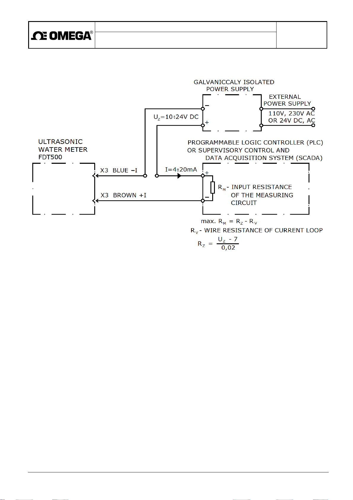
External power source voltage: Uz = 10V to 24V
The highest possible resistance of the current loop (including the input resistance of the connected signal
processing equipment):
Rz [Ω] =
Uz [V] - 7
0.02
Example: for power source voltage Uz = 12V the maximum current loop resistance is 250Ω.
Flow rate measurement
In cases where the current output 4 to 20mA (-A, optional) is associated with instantaneous flow rate of the
measured fluid, then, upon exceeding the maximum flow-rate value (Q4), the output current signal will no longer
grow and the error message (ERR) will appear on the meter display.
Pressure measurement (-PS, optional)
The FDT500 water meters of compact design may use a current loop for indication of instantaneous values of the
flowing fluid pressure (-PS, optional). This is one of the additional meter functions that need be preset during the
meter manufacture.
The pressure measurement function (-PS, optional) can either be configured independently or in combination with
the pulse output feature (see Section 6.2.1.).
The current output 4 to 20mA (-A, optional) corresponds to the relative pressure values of 0 to16 bar (the pressure
indicated at empty piping is 0 bar).
Page 20
Project design, meter installation and service manual
Battery-powered ultrasonic water meters
of the FDT500 series
Current output 4 to 20mA (-A, optional) connection diagram
Page 20 of 28
Page 21
Project design, meter installation and service manual
Battery-powered ultrasonic water meters
of the FDT500 series
Page 21 of 28
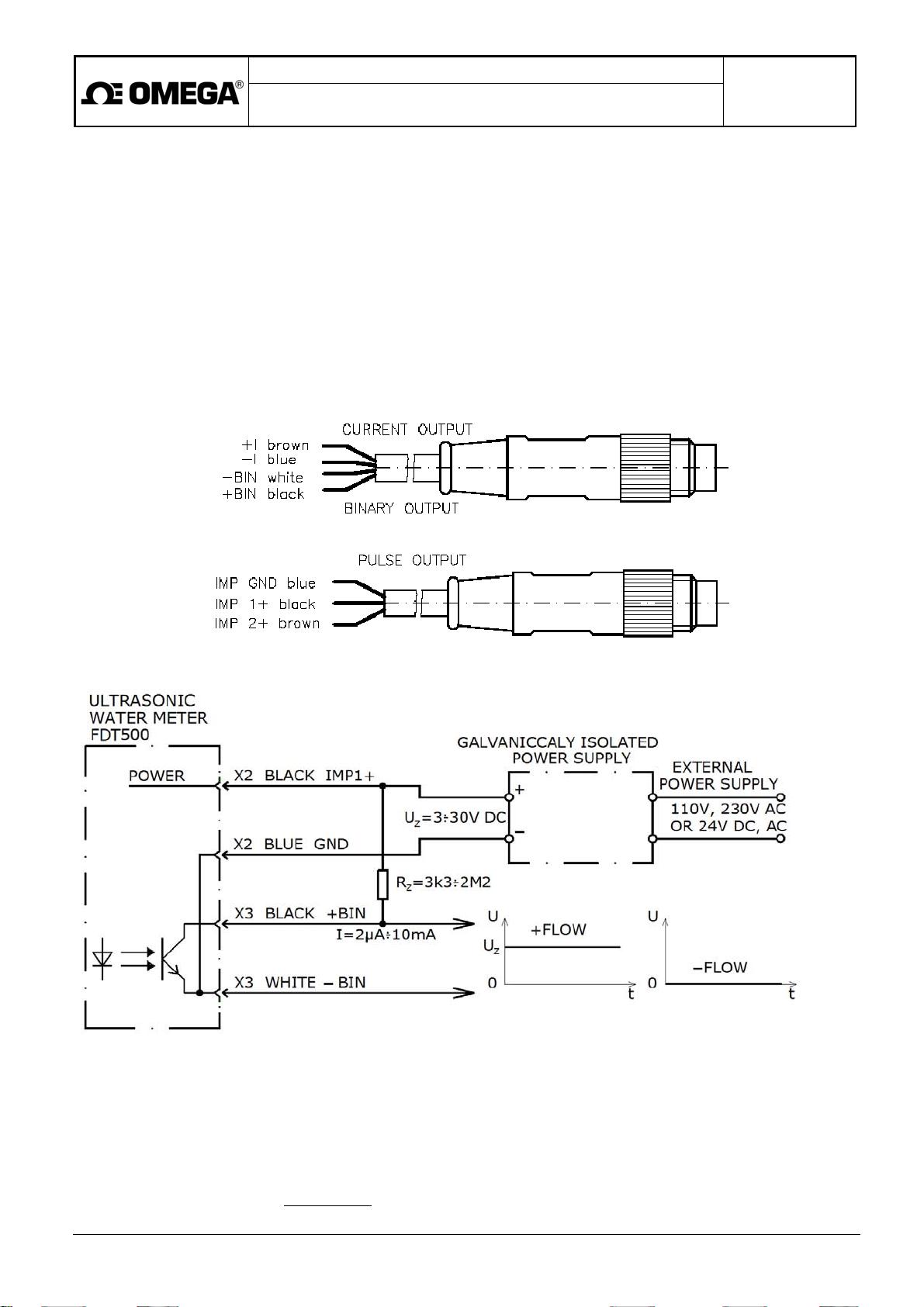
6.2.3. Binary flow-direction indication
In cases where the current output 4 to 20mA (-A, optional) is used for the purposes of instantaneous flow rate
measurement (see Section 6.2.2. below), the flow direction can be indicated using the binary output.
To process the binary output signals, the electronic unit need be preset for this function during the meter
manufacture.
Binary output signals +BIN and – BIN are connected to the socket of connector X3. It is a passive and
insulated output.
Each passive output shall be powered from an independent insulated power source.
The binary output function requires external power supply connected to the pulse output IMP1. That is why both
connectors X3 and X2 (and the associated signal cables) need be used.
The black conductor of the X2 cable shall be connected to external power source of voltage Uz across resistor
100kΩ. The brown and blue conductor of the same cable shall remain unconnected.
X3
Binary output connection diagram
X2
If the fluid flow direction is as indicated by the arrow on the sensor body (+FLOW), the binary output will be at the
source voltage level (Uz). In cases of opposite flow direction (-FLOW), the binary output voltage will be 0V.
Binary output parameters (a MOSFET transistor, channel N):
• External power source voltage Uz = 3V to 30V
• Current loading: 2µA to 10mA
Load resistance value:
Rz [
Ω]
=
Uz [V]
I [A]
Page 22
Project design, meter installation and service manual
Battery-powered ultrasonic water meters
of the FDT500 series
Page 22 of 28
6.3. Power source
6.3.1. Battery lifetime and replacement
In cases of standard water meter configuration, the battery lifetime is 8 years. The need for battery replacement will be
indicated by the corresponding symbol shown on the meter display. To access the battery compartment, it is
necessary to remove the assembly seals at the top and at the bottom of the electronic unit box.
Upon the battery removal, the following data will be saved in the meter memory:
• The total volume passed through the meter sensor in either fluid flow direction;
• The meter parameter setting;
• The archived data.
The electronic unit does not include any real-time circuit independent of power supply.
To retain the stored time data during the battery replacement operation, the following procedure should be carried out
(with water meters including the data archiving function):
• Prior to battery removal, read out the archived data using the SW ARCHTERM program (sold separately);
• After the battery replacement, use the SW ARCHTERM program (sold separately) again to read the archive
setting parameters, whereby the correct time and date will automatically be set;
• Delete the archived data.
Recommended battery type
In consideration of the long lifetime requirement, the recommended battery type is TADIRAN SL 2780/S 3,6 V/19 Ah.
In cases of air transport where the permitted lithium content in the battery is < 1 g, a smaller battery SAFT Lithium 3,6
V/3,6 Ah, type designation LSH 14 light, accommodated in a plastic container of size D can also be used.
The lifetime of that alternative battery in the water meter of standard configuration is 1 year. This battery can be at any
time replaced by recommended battery type with capacity 19Ah.
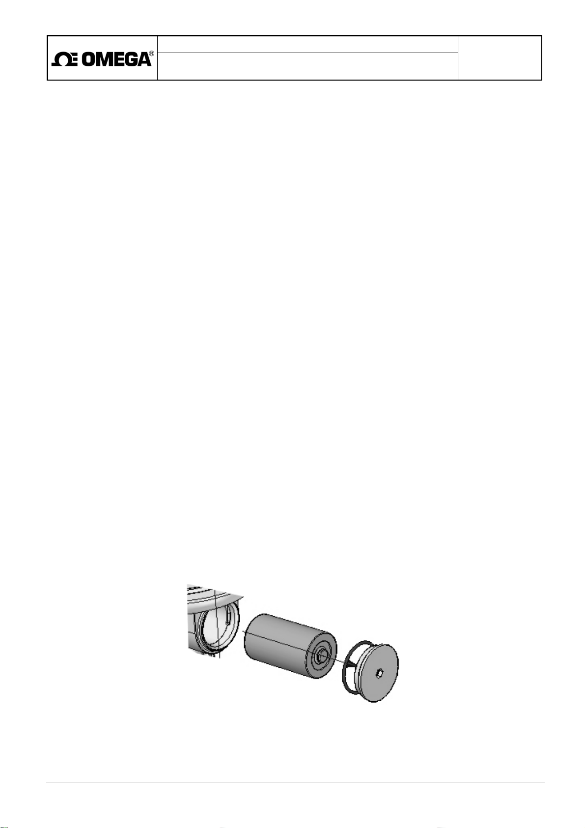
Battery replacement procedure
To remove the old battery, screw off, using Alien wrench 6, the lid on the battery compartment sealed with an O-ring
33x1.5mm. Lift the front contact (against the forcing spring) and remove the battery.
The new battery shall be inserted into its compartment in the electronic unit with the negative pole at the bottom.
Mind the battery polarity – the incorrect polarity may irreparably damage the electronic unit circuits.
Insert the new battery in its compartment; while pressing the battery down, return the front contact to operating
position. The positive battery pole must have a reliable contact with the front spring-loaded contact.
Screw on the lid with the sealing O-ring, tighten and attach a stick-on assembly seal onto the contact plane.
Page 23

Project design, meter installation and service manual
Battery-powered ultrasonic water meters
of the FDT500 series
Page 23 of 28
6.3.2. Electronic unit powered from current loop
The power to the electronic unit of the FDT water meters of the FDT500 series including additional functions can
be supplied directly from a current loop. In that case, a special electronic module shall be inserted into the battery
compartment.
This current output 4 to 20mA (-A, optional) function must be preset during the meter manufacture.
Upon selection of the current-loop feeding option, the data archiving and reading functions cannot be
used.
Meter operational start in cases of power supply from the current loop
Unlike the battery-powered meter, water meters configured for power supply from the current loop are dispatched
in deactivated condition (including the display).
Install the meter sensor into the piping. The display will light up only after the current loop has been connected
and energised. The correct meter function is then indicated by the vertical slash blinking with the measurement
frequency (1Hz) and the ERR message shown on the LC display. Following the sensor flooding and bleeding, the
ERR symbol will disappear and the meter will start its normal measuring functions. Using the control pushbutton,
check the function of selecting the desired measured quantity to be shown on the display.
The current output 4 to 20mA (-A, optional) connection (connector X3) is as described in Section 6.2.2.
6.4. Communication interface
The FDT water meters are provided with insulated communication interface RS232 facilitating:
• Reading of all measured quantities:
o Instantaneous flow rate + /-
o Total volume passed through the meter sensor + /-
o Fluid pressure (-PS, optional) in the sensor
• Flow-meter parameter setting
• Reading of the archived data, including:
o Flow rate
o Total volume passed through the meter sensor in the given direction (+ or -)
o Pressure of the flowing fluid
o Real times of any error condition start and termination
o Descriptions of diagnosed errors
o Watch dog (WD) actions
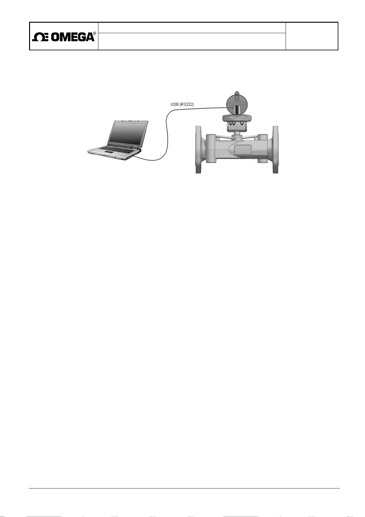
Connection to the communication interface RS232 is possible using:
• Optical probe, or
• Cable via connector X1
Page 24
Project design, meter installation and service manual
Battery-powered ultrasonic water meters
of the FDT500 series
Page 24 of 28
6.4.1. Communication via optical probe (-OPT, optional)
The optical probe shall be placed in a recession on the electronic unit cover where the exact probe position is secured
by an arrest pin and the probe is held on the cover by means of a permanent magnet.
The meter software makes it possible to archive all measured quantities with sampling frequency selectable in the
range from 1 minute to 1 year. Apart from the measured data, archived also are error messages (see Section 6.5.)
and date and time of their occurrence.
To set the archive parameters and read the archived data (-OPT, optional), the meter user shall have the necessary
tools herein referred to as "SVAO 1 set".
The SVAO 1 set includes:
• Optical probe OS 7.0 and a 2m cable terminated with an USB connector
• CD including:
o Program SW ARCHTERM (sold separately) for setting the archive parameters and reading the
archived data (-OPT, optional)
o Program SW ARCHTERM manual
o Controllers for optical probe OS7.0 USB
Page 25
Project design, meter installation and service manual
Battery-powered ultrasonic water meters
of the FDT500 series
Page 25 of 28
6.4.2. Communication via RS232 cable
The meter software makes it possible to archive all measured quantities with sampling frequency independently
selectable in the range from 1 minute to 1 year. Apart from the measured data, archived also are error messages (see
Section 6.5.) and date and time of their occurrence.
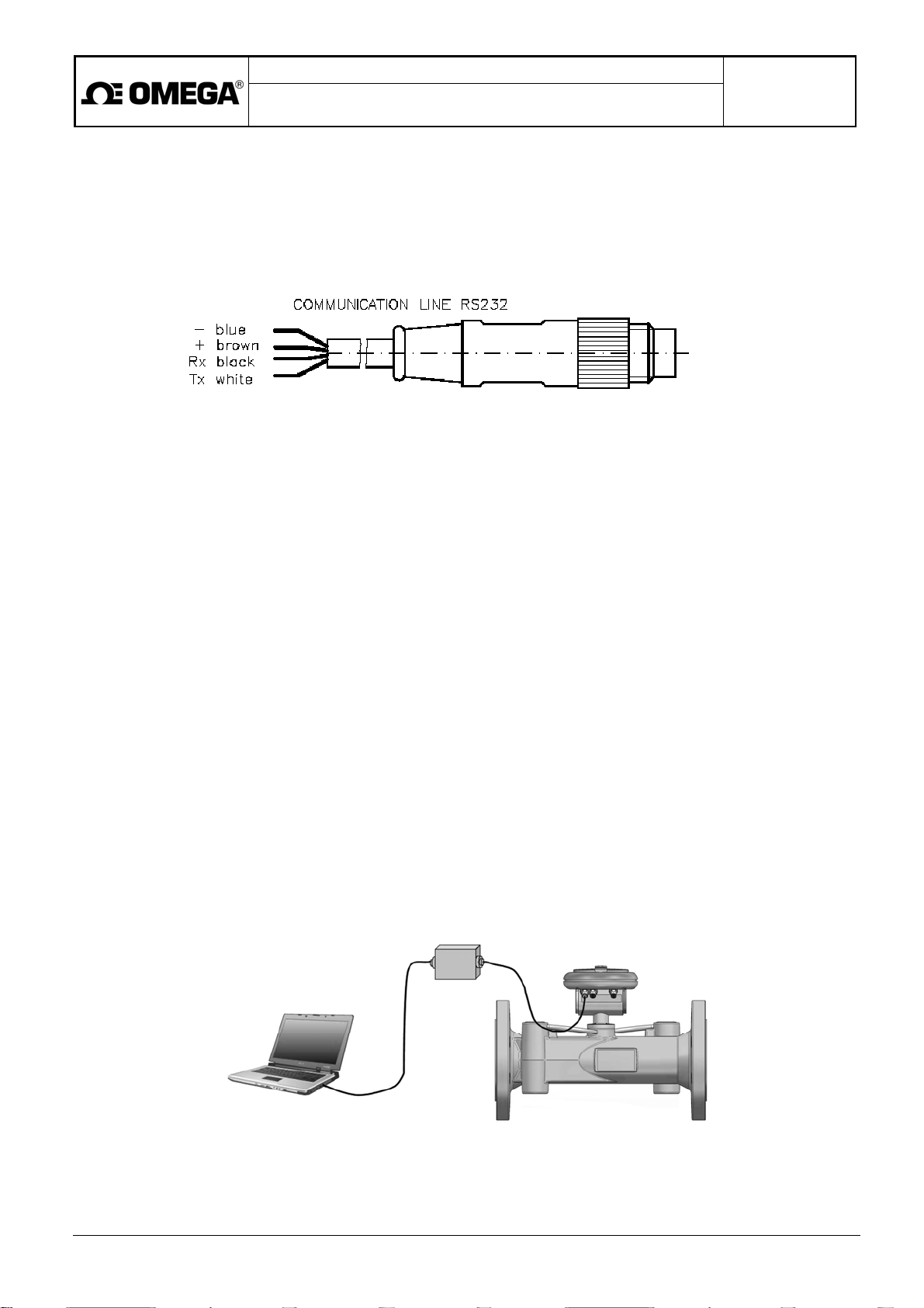
The insulated RS232 communication interface is accessible via connector X1.
X1
To set the archive parameters and read the archived data, the meter user shall have the necessary tools herein
referred to as "SVAK 1 set".
The SVAK 1 set includes:
• The RS232 communication cable 5 metres long, provided with a plug matching connector X1 on one end
and a 9-pin Canon connector on the other end (to be connected to a computer).
• CD including:
o Program SW ARCHTERM (sold separately) for setting the archive parameters and reading the
archived data
o Program SW ARCHTERM manual
Should the meter location be difficult to access, additional tools described below are available to ensure higher
operator comfort.
Connection to RS232 interface:
• Connecting box meeting the IP68 requirements with a 5m cable terminated with a 9-pin Canon connector
Connection to USB interface:
• Connecting box meeting the IP68 requirements with a 5m cable terminated with a 9-pin Canon connector
• RS232-USB convertor
• CD including:
o RS232-USB convertor user manual
o Controllers for the Windows operation system
At all times when the communication interface is not used, connector X1 shall be tightly closed using a
screw-on cover M8x1 in combination with a matching O-ring.
RS232 (USB Driver)
Page 26

Project design, meter installation and service manual
Battery-powered ultrasonic water meters
of the FDT500 series
Page 26 of 28
6.5. Identification of errors listed in the archive
Any meter failure will be reported at the meter display by means of the ERR symbol.
The detailed information on failures is stored in the archive in the format Date, Time, EBx or EEx where x is the error
number (1 to 4), EB indicates the error condition start and EE the error condition termination.
ERR1 - the sensor is impenetrable for ultrasonic signal
The frequent cause of this error condition is aerated sensor, air bubbles or mechanical particles scattered in
the measured fluid, or disregarding the system design rules referred to in Section 5 hereof. In the latter case,
check the meter placement for possible nonconformities. Defects originating from incorrect meter
placement in piping cannot be claimed and subject to manufacturer's warranty.
ERR2 - too great difference between the signal flight times in and against the fluid flow direction
The cause of this error can be aeration of one ultrasonic probe which may be a temporary condition at the
time when the piping system is being filled with the fluid. Heavy contamination of the head part of one probe
may have a similar effect. The method of correction should be consulted with the meter manufacturer.
ERR3 - error of internal A/D converter
The cause of this error can be strong electromagnetic interference or a meter defect.
Check the meter placement and electrical connections in reference to the correct system design rules as
referred to in Section 5 hereof.
ERR4 - instantaneous flow rate is higher than overloading flow rate value Q4
The archived data include, apart from the error messages, information on any WD actions. The Watch Dog action
consists of the meter restart in cases of discontinuation of the normal meter operation due to extreme external
interference or internal hardware malfunction.
Low battery voltage and the need to replace the battery will be indicated by the battery sign lighted on the meter
display. Information on the battery voltage can also be obtained via the system communication channel.
If the display goes completely out, check the battery voltage. It should higher than 3V. To replace the flat battery,
follow the instructions in Section 6.3.1. Should the meter fail to restore its functions with the new battery, send it to the
manufacturer for repair.
7. CALIBRATION
Ultrasonic water meters are supplied calibrated in three points according to standard EN 14154-3.
To check the meter functions, precision or calibration, use always the test methods specified in or conforming to
the requirements of standard EN 14154-3.
Page 27

WARRANTY/DISCLAIMER
OMEGA ENGINEERING, INC. warrants this unit to be free of defects in materials and workmanship for a
period of 13 months from date of purchase. OMEGA’s WARRANTY adds an additional one (1) month
grace period to the normal one (1) year product warranty to cover handling and shipping time. This
ensures that OMEGA’s customers receive maximum coverage on each product.
If the unit malfunctions, it must be returned to the factory for evaluation. OMEGA’s Customer Service
Department will issue an Authorized Return (AR) number immediately upon phone or written request.
Upon examination by OMEGA, if the unit is found to be defective, it will be repaired or replaced at no
charge. OMEGA’s WARRANTY does not apply to defects resulting from any action of the purchaser,
including but not limited to mishandling, improper interfacing, operation outside of design limits,
improper repair, or unauthorized modification. This WARRANTY is VOID if the unit shows evidence of
having been tampered with or shows evidence of having been damaged as a result of excessive corrosion;
or current, heat, moisture or vibration; improper specification; misapplication; misuse or other operating
conditions outside of OMEGA’s control. Components in which wear is not warranted, include but are not
limited to contact points, fuses, and triacs.
OMEGA is pleased to offer suggestions on the use of its various products. However,
OMEGA neither assumes responsibility for any omissions or errors nor assumes liability for
any damages that result from the use of its products in accordance with information provided
by OMEGA, either verbal or written. OMEGA warrants only that the parts manufactured by the
company will be as specified and free of defects. OMEGA MAKES NO OTHER WARRANTIES OR
REPRESENTATIONS OF ANY KIND WHATSOEVER, EXPRESSED OR IMPLIED, EXCEPT THAT OF
TITLE, AND ALL IMPLIED WARRANTIES INCLUDING ANY WARRANTY OF MERCHANTABILITY
AND FITNESS FOR A PARTICULAR PURPOSE ARE HEREBY DISCLAIMED. LIMITATION OF
LIABILITY: The remedies of purchaser set forth herein are exclusive, and the total liability of
OMEGA with respect to this order, whether based on contract, warranty, negligence,
indemnification, strict liability or otherwise, shall not exceed the purchase price of the
component upon which liability is based. In no event shall OMEGA be liable for
consequential, incidental or special damages.
CONDITIONS: Equipment sold by OMEGA is not intended to be used, nor shall it be used: (1) as a “Basic
Component” under 10 CFR 21 (NRC), used in or with any nuclear installation or activity; or (2) in medical
applications or used on humans. Should any Product(s) be used in or with any nuclear installation or
activity, medical application, used on humans, or misused in any way, OMEGA assumes no responsibility
as set forth in our basic WARRANTY/DISCLAIMER language, and, additionally, purchaser will indemnify
OMEGA and hold OMEGA harmless from any liability or damage whatsoever arising out of the use of the
Product(s) in such a manner.
RETURN REQUESTS/INQUIRIES
Direct all warranty and repair requests/inquiries to the OMEGA Customer Service Department.
BEFORE RETURNING ANY PRODUCT(S) TO OMEGA, PURCHASER MUST OBTAIN AN AUTHORIZED
RETURN (AR) NUMBER FROM OMEGA’S CUSTOMER SERVICE DEPARTMENT (IN ORDER TO AVOID
PROCESSING DELAYS). The assigned AR number should then be marked on the outside of the return
package and on any correspondence.
The purchaser is responsible for shipping charges, freight, insurance and proper packaging to prevent
breakage in transit.
FOR WARRANTY RETURNS, please have the
following information available BEFORE
contacting OMEGA:
1. Purchase Order number under which the product
was PURCHASED,
2. Model and serial number of the product under
warranty, and
3. Repair instructions and/or specific problems
relative to the product.
OMEGA’s policy is to make running changes, not model changes, whenever an improvement is possible. This affords
our customers the latest in technology and engineering.
OMEGA is a registered trademark of OMEGA ENGINEERING, INC.
© Copyright 2013 OMEGA ENGINEERING, INC. All rights reserved. This document may not be copied, photocopied,
reproduced, translated, or reduced to any electronic medium or machine-readable form, in whole or in part, without the
prior written consent of OMEGA ENGINEERING, INC.
FOR NON-WARRANTY REPAIRS,
for current repair charges. Have the following
information available BEFORE contacting OMEGA:
1. Purchase Order number to cover the COST
of the repair,
2. Model and serial number of the product, and
3. Repair instructions and/or specific problems
relative to the product.
consult OMEGA
Page 28

Where Do I Find Everything I Need for
Process Measurement and Control?
OMEGA…Of Course!
Shop online at omega.com
TEMPERATURE
MU
Thermocouple, RTD & Thermistor Probes, Connectors, Panels & Assemblies
MU
Wire: Thermocouple, RTD & Thermistor
MU
Calibrators & Ice Point References
MU
Recorders, Controllers & Process Monitors
MU
Infrared Pyrometers
PRESSURE, STRAIN AND FORCE
MU
Transducers & Strain Gages
MU
Load Cells & Pressure Gages
MU
Displacement Transducers
MU
Instrumentation & Accessories
FLOW/LEVEL
MU
Rotameters, Gas Mass Flowmeters & Flow Computers
MU
Air Velocity Indicators
MU
Turbine/Paddlewheel Systems
MU
Totalizers & Batch Controllers
SM
pH/CONDUCTIVITY
MU
pH Electrodes, Testers & Accessories
MU
Benchtop/Laboratory Meters
MU
Controllers, Calibrators, Simulators & Pumps
MU
Industrial pH & Conductivity Equipment
DATA ACQUISITION
MU
Data Acquisition & Engineering Software
MU
Communications-Based Acquisition Systems
MU
Plug-in Cards for Apple, IBM & Compatibles
MU
Data Logging Systems
MU
Recorders, Printers & Plotters
HEATERS
MU
Heating Cable
MU
Cartridge & Strip Heaters
MU
Immersion & Band Heaters
MU
Flexible Heaters
MU
Laboratory Heaters
ENVIRONMENTAL
MONITORING AND CONTROL
MU
Metering & Control Instrumentation
MU
Refractometers
MU
Pumps & Tubing
MU
Air, Soil & Water Monitors
MU
Industrial Water & Wastewater Treatment
MU
pH, Conductivity & Dissolved Oxygen Instruments
M-5462/0415
 Loading...