

Page 1
User’s Guide
Shop online at
omega.com
e-mail: [email protected]
®
For latest product manuals:
omegamanual.info
MADE IN CHINA
FDT-21W
Wall Mounted
Ultrasonic Flowmeter
Page 2

OMEGAnet®Online Service Internet e-mail
omega.com [email protected]
Servicing North America:
U.S.A.: Omega Engineering, Inc., One Omega Drive, P.O. Box 4047
ISO 9001 Certified Stamford, CT 06907-0047 USA
Canada: 976 Bergar
Laval (Quebec), H7L 5A1 Canada
Toll-Free: 1-800-826-6342 TEL: (514) 856-6928
FAX: (514) 856-6886 e-mail: [email protected]
For immediate technical or application assistance:
U.S.A. and Canada: Sales Service: 1-800-826-6342/1-800-TC-OMEGA
Customer Service: 1-800-622-2378/1-800-622-BEST
Engineering Service: 1-800-872-9436/1-800-USA-WHEN
®
®
®
Servicing Asia:
China: 1698 Yi Shan Road, Unit 102,
Min Hang District, Shanghai, China
Hotline: 800 819 0559/400 619 0559 e-mail: [email protected]
Servicing Europe:
Benelux: Toll-Free: 0800 099 3344 TEL: +31 20 347 21 21
FAX: +31 20 643 46 43 e-mail: [email protected]
Czech Republic: Frystatska 184
733 01 Karviná, Czech Republic
Toll-Free: 0800-1-66342 TEL: +420-59-6311899
FAX: +420-59-6311114 e-mail: [email protected]
France: Toll-Free: 0805 541038 TEL: 01 57 32 48 17
FAX: 01 57 32 48 18 e-mail: [email protected]
Germany/ Austria: Daimlerstrasse 26
D-75392 Deckenpfronn, Germany
Toll-Free: 0800 8266342 TEL: +49 (0) 7056 9398-0
FAX: +49 (0) 7056 9398-29 e-mail: [email protected]
United Kingdom: OMEGA Engineering Ltd.
ISO 9001 Certified One Omega Drive, River Bend Technology Centre, Northbank
Irlam, Manchester M44 5BD United Kingdom
Toll-Free: 0800-488-488 TEL: +44 (0) 161 777-6611
FAX: +44 (0) 161 777-6622 e-mail: [email protected]
It is the policy of OMEGA Engineering, Inc. to comply with all worldwide safety and EMC/EMI
regulations that apply. OMEGA is constantly pursuing certification of its products to the European New
Approach Directives. OMEGA will add the CE mark to every appropriate device upon certification.
The information contained in this document is believed to be correct, but OMEGA accepts no liability for any
errors it contains, and reserves the right to alter specifications without notice.
WARNING: These products are not designed for use in, and should not be used for, human applications.
Page 3

1 of 21
TABLE of CONTENTS
Page #
1. OUTLINE……………………………………………………………………………………………….. 2
1.1 Principle of Measurement……………………………………………………………………. 3
2. Starting Measurement……………………………………………………………………………… 4
2.1 Wall-Mounted, Fixed Style Ultrasonic Flow Meter…………………………………………. 5
3. Display and Operation……………………………………………………………………………… 6
3.1 Key Functions…………………………………………………………………………………… 6
3.1.1 Overview………………………………………………………………………………… 6
3.1.2 Menu Information………………………………………………………………………. 7
3.1.3 Parameter Solidification – Options……………………………………………..……. 9
3.1.4 Zero Point Setup & Zero Point Solidification……………………………………….. 9
3.1.5 Factory Use: Scaling Factor Solidification………………………………………….. 9
3.1.6 Applying Analogue Functions………………………………………………………… 9-10
3.1.7 Analogue Interface: Introduction & Methods……………………………………….. 10
3.1.8 Serial Peripheral: Introduction……………………………………………………….. 10
3.2 Factory Default: Restoring…………………………………………………………………….. 10
4. Installing Transducers………………………………………………………………………… 10
4.1 Unpacking…………………………………………………………………………………..…… 10
4.2 Power Supply & Cables……………………………………………………………………...… 11
4.3 Installation Requirements…………………………………………………………………..…. 11
4.3.1 Choosing Measurement Points………………………………………………………… 12-14
4.3.2 Well Installation Requirements………………………………………………………..… 15
4.4 Pipe Parameters Settings………………………………………………………………………. 15
4.5 Installing a Clamp Type Transducer…………………………………………………………… 16
4.5.1 Installation Space Information…………………………………………………………… 16
4.5.2 Installation Methods: V & Z Types..……………………………………………………. 17-18
4.7 Transducer Installation – Checking…………………………………………………………… 18
4.7.1 Signal Strength…………………………………………………………………………… 18
4.7.2 Signal Quality (Q value) ………………………………..………………………………. 19
4.7.3 Total Transit Time (Delta Time)…………………..……………………….……………. 19
4.7.4 Transit Time Ratio………………………………………………………….……………. 19
4.7.5 Installation Guideline: Summary…………………………..……………………….….. 20
5. Troubleshooting…………………………………………………………………………………… 20
Page 4
2 of 21
1. Outline
§1.1 Principle of Measurement
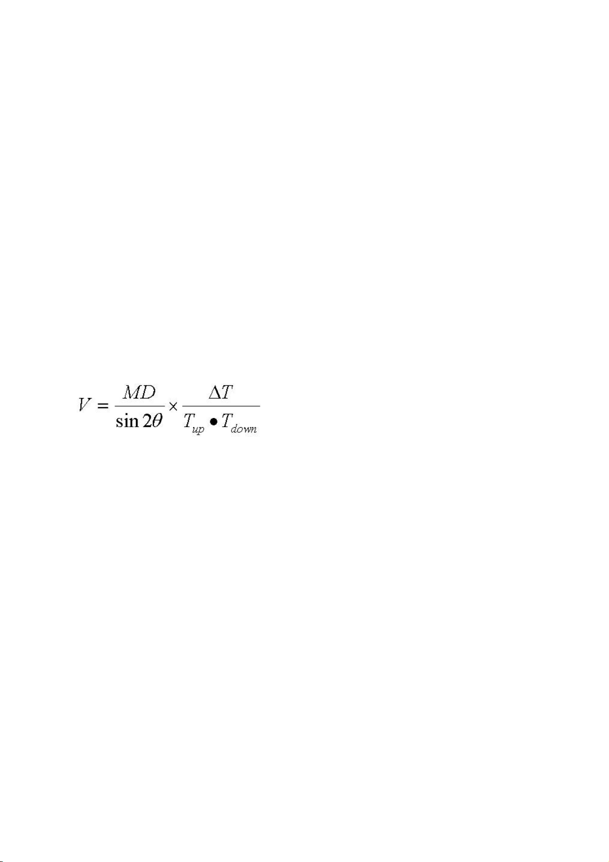
When an ultrasonic beam is transmitted through flowing liquid, there will be a difference
between the upstream and downstream transit time (travel time or time of flight), which is
proportional to flow velocity. When the fluid is flowing, counter flow transit time is more than direct
flow transit time. Please see formula below:
.
Remarks:
Θ
= The angle between the ultrasonic and
the flow
M
= Transit times of the ultrasonic beam
D
= The internal diameter of the pipe
Tup
= Transit time in forward direction
Tdown
= Transit time in reverse direction
ΔT
= Tup – down
F=900
×π×D2×
V
F =
Instant flow rate (unit: m³/hour)
D
= Inside pipe diameter (unit: m)
V
= Flow velocity (unit: m/s)
Page 5

3 of 21
2. Starting Measurement
The instruments are comprised of a measuring main board, function extending module and a display
operation terminal. Users can choose the right configuration according to their requirements.
The easiest configuration only needs a measuring main board and a pair of transducers to complete the
function of flow measurement.
§2.1 Wall Mounted, Fixed-style, Ultrasonic Flow Meter
Available transducers include the following types: clamp-on, insertion and in-line.
Technology features:
1. Operating Power: AC 85—264V.
2. Repeatability: Better than 0.2%.accuracy: better than 1%.
3. Signal Output:
▲ One channel standard isolation RS485 output
▲ One channel isolation 4-20mA or 0-20mA active output
▲ Dual channel OCT output (programmed between the OCT pulse width (6-1000ms),
default (200ms)
▲ One channel isolation relay output, with positive, negative, net accumulation pulses and
different alarm signals.
4. Signal Input:
▲ Two channel three wire system (for pressure, level, or temperature)
▲ PT100 platinum resistor input loop, accuracy: 0.1%.
5. Display: 2*10 backlit LCD (Chinese and English optional).
6. Operating: 4*4 tactile keypad.
7. Other functions:
▲ Automatic memory of the positive, negative and net totalized flow rate of the last 512 days,
128 months, 10years;
▲ Automatic memory of the on/off power time and the flow rate of the last 30 times;
▲ Reset automatically or by hand;
▲ Read data through Modbus communication protocol.
8. Protection level: mainframe: IP65, transducer: IP68
9. Transducer: M2: clamp-on.
Page 6
4 of 21
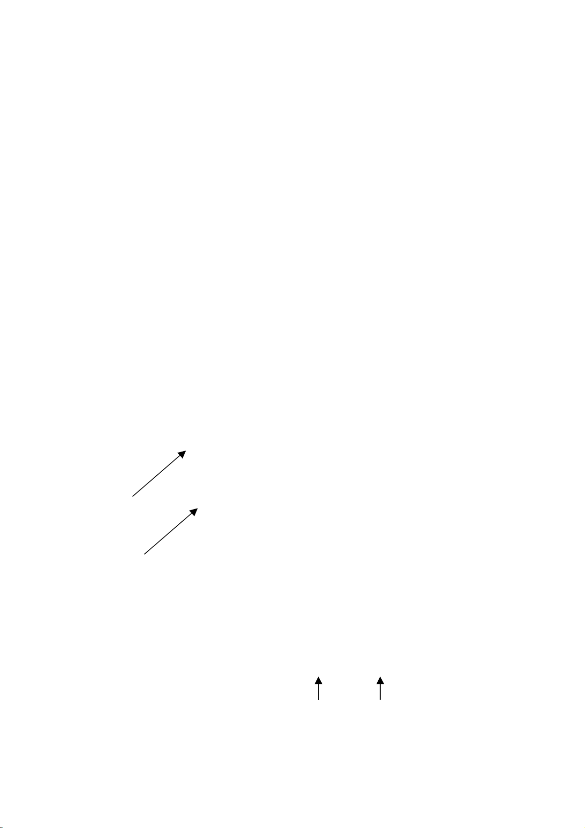
■ Main board wiring map and outline size:
Grounded Wires: In cludes both upstream and downstream ground wires.
18 Version Main Board
Page 7

5 of 21
Page 8
6 of 21
3. Display and Operation
3.1 Key Functions
3.1 .1 Overview
The FDT-21W Ultrasonic Flow Meter can use the 16 keys keyboard monitor, the 16 keys parallel and
serial port keyboard which includes: 10 digit keys, 2 up/down arrow keys, 1 menu key (M), 1 enter key, 1
decimal point key and 1 backspace key. The keyboard allows users to program quickly and easily.
Delete the usage of 4 keys keyboard
Here are some usages of 16 keys keyboard:
▲ “ 0 – 9” and “·”are used to input numerical value and menu number.
▲ “◄ “ key is used to left backspace or delete left character.
▲ “<▲/+>” and “<▼/- >” are used to shift to upper and lower menu. When inputting digits,
these are equal to the “plus” or “minus” keys.
▲ The “Menu” key brings up the main menu.
First, press the “Menu” key and then your topic.
A related menu is pulled up listing all subtopics available.
Select the related number for your specific subtopic.
(ex: to get the outside pipe diameter, press “Menu” and “11”. “M11” is the address
code of outside pipe diameter parameter setting)
▲ The “<ENT>” key is mainly used to ensure the input digit and chosen content. The other
function is to press it to enter “modify” status before setting parameters.
▲ The keypad buzzer can be shut down at the 25th Item of M77.
▲ See section 4.4 for Quick Pipe Parameter Settings..
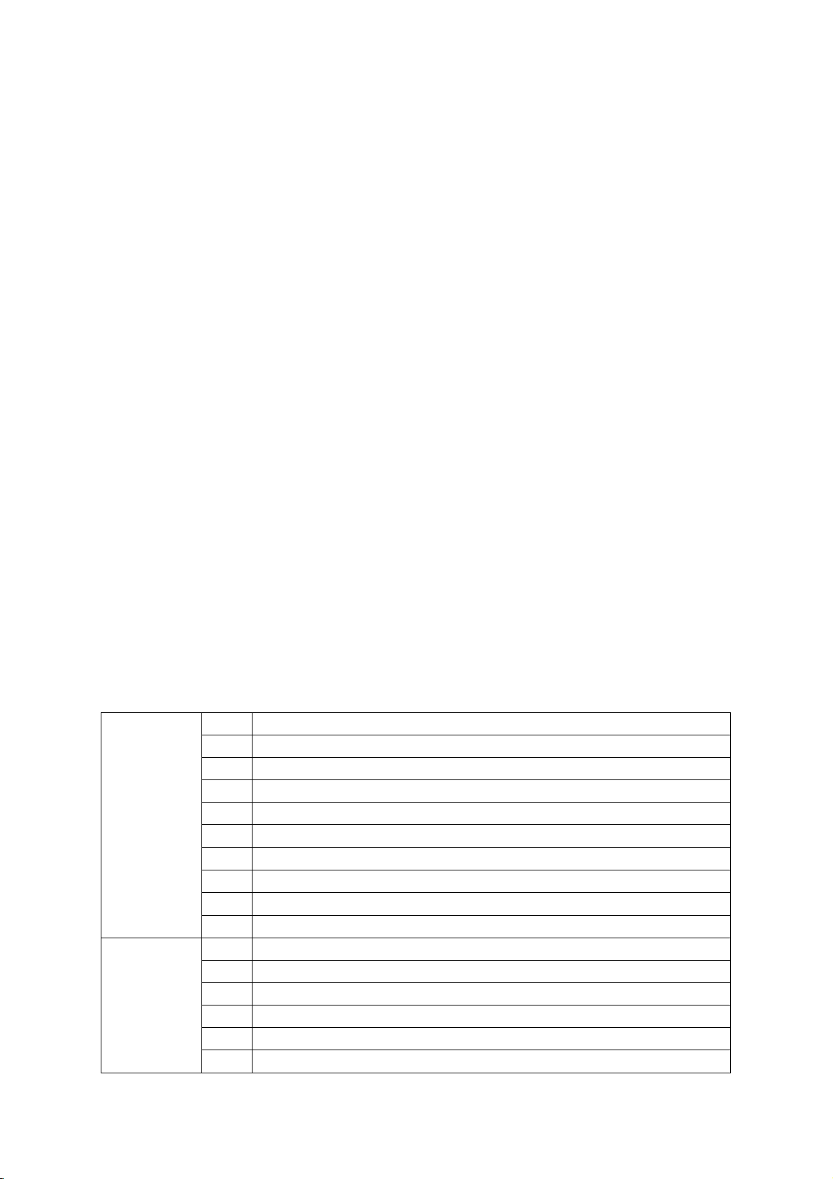
3.1.2 Detailed information of Menu
Flow Rate
&
Flow
Totalizer
Display
M00
Display instant flow rate/net totalizer (adjust the units in M30-M32)
M01
Display instant flow rate/instant flow velocity (adjust the units in M30-M32)
M02
Display instant flow rate/positive totalizer (adjust the units in M30-M32)
M03
Display instant flow rate/negative totalizer (adjust the units in M30-M32)
M04
Display instant flow rate/date & time
M05
Not Used
M06
Display temperature input T1,T2
M07
Display analog input A13, A14
M08
Display system error code
M09
Display the net accumulative total flow
Initial
Set-Up
M10
Input outside perimeter of pipe
M11
Input pipe outer diameter, data range: 0-18000mm
M12
Input pipe wall thickness
M13
Input pipe inner diameter
M14
Choose pipe materials
M15
Input sound velocity of pipe material
Page 9
7 of 21
Initial
Set-Up
(cont…)
M16
Choose liner
M17
Input the sound velocity of liner
M18
Input the thickness of liner
M19
Input inner pipe wall & absolute degree of roughness
M20
Choose fluids
M21
Input fluid velocity
M22
Input fluid viscosity
M23
Choose the types of transducers, selection includes more than 20 types
M24
Choose transducer installation method
M25
Display transducer installation space
M26
Enter set-up parameters
M27
Fast access to history installation parameters setting at points measured
before.
M28
When setting with a poor signal, keep the last data entered by choosing
“yes”; this will keep the last measurement entered.
M29
Setting a signal strength when the pipe flow is about to be emptied.
Ex: If a signal strength level of “65” is entered when it is actually lower than
65, the flow meter will not recognize the signal. The flow meter interprets
this as the pipe does not have any liquid in it and therefore is empty. The
flow value end result displayed will be a zero value.
Flow Unit
Setup
M30
Choose metric or imperial unit
M31
Choose instant flow rate unit
M32
Choose totalizer
M33
Choosing the totalizer multiplying factor which function is to multiply
totalizer data range, normally set it as X1
M34
Net totalizer switch
M35
Positive totalize switch
M36
Negative totalize switch
M37
Restore parameters setup before leaving factory and reset totalize
M38
Manual totalize (the key to control on/off)
M39
Choose operating language, 8 different languages
M3
Not Used
Choosing
Setup
M40
Damper Coefficient
M41
Input low flow velocity cutoff value
M42
Setup static zero point
M43
Clear zero point setup and manually setup zero point. Restore default
before leaving factory.
M44
Set up zero point deviant by hand
M45
Meter coefficient, rectification coefficient
M46
Input network address identification number (IDN)
M47
Password protecting operation. After the meter is setup with a password,
only browse menus available without any modification.
M48
Input degree of linearity, broken line rectification data. At most, there are
Page 10
8 of 21
12 broken line segments that are used to rectify meter but with no linearity.
M49
Network communication tester. Check data transferred from the
computer to judge the problems during communication.
Scheduled
Time
Output
M50
Optional setup of data. Output at scheduled time. Choose output
content at scheduled time to print, more than 20 to select.
M51
Setup output time at scheduled time.
M52
Printing data flow direction control by default. Printing data will flow directly
to the printer hung. Setup printing data output to outside serial port
(RS485).
AI5 Setup
M53
Display analogue input AI5 (reserved for the battery powered main board).
Input and
Output
Setup
M54
Setup of OCT totalizer pulse output, pulse width, range: 6 Ms-1000Ms.
M55
Choose current loop mode.
M56
Corresponding data to output of current loop 4mA or 0mA.
M57
Corresponding data to output of current loop 20mA.
M58
Verification of current loop output. Applied to check whether current loop
is normal or not.
M59
Present output of current loop.
M60
Date/Time set up. The date/time of the new flow meter is set by CPU.
When upgrading software, adjust the date and time to display correctly.
M61
Software version information and Electronic Serial Number (ESN).
M62
Setup serial port parameter.
M63
Communication protocol selection.
Two options: a) MODBUS-RTU uses the binary system MODUS-RTU
protocol and b) MODBUS-ASCII+ uses ASCII protocol.
At this time, it can support several protocols simultaneously, including
MOSBUS-ASCII, FUJI protocol, Meter-BUSx protocol etc.
M64
Analogue input AI3.
M65
Analogue input AI4.
M66
Analogue input AI5.
64–65: By entering measuring range, the flow meter will turn current signal
into data range users need, so the display related analogue input that
corresponds to physical parameter data.
M67
Setup frequency range of frequency output signal. Frequency signal
output represents instant flow rate value by signal frequency value default:
0-1000, max-range: 0-999Hz.output frequency signal by special frequency
output unit.
M68
Setup lower limit flow of frequency signal output.
M69
Setup upper limit flow of frequency signal output.
M70
LCD backlit control.
M71
LCD contrast ratio control.
M72
Work timer. Logs work time of meter by unit of second; time can be reset
M73
Setup lower limit flow of frequency signal output
M74
Setup upper limit flow of frequency signal output
Page 11
9 of 21
M75
LCD backlit control.
M76
LCD contrast ratio control
73-75: By establishing the lower and upper limit of alarm, confirm range.
When actual flow is over the set range in this window, an output alarm
signal can be created. Alarm signal can be transferred to the outside by
setting up OCT or relay.
M77
Beeper setup options
M78
Setup Open Collector Transistor output (OCT) options
M79
Setup relay (OCT2) output options
M80
Choose input signal of batch controller
M81
Batch controller
M82
M-89
Not Used
Design
Diagnosis
*M90
Displays signal strength and quality
*M91
Displays transit time ratio
M92
Displays calculated fluid sound velocity
M93
Displays total transit and delta times
M94
Displays Reynolds number and pipe coefficient
M95
Displays positive and negative heat quantity totalizer.
Also start cycle display function.
Added
Menu
Window
+0
Displays time when powered on/off and flow rate
+1
Displays total working time of flow meter
+2
Displays last time when powered off.
+3
Displays flow rate of last power off
+4
Displays total times meter was powered on
+5
Scientific calculator
Hardware
Adjustment
Menu
Window
.2
Stores static zero point
.5
Threshold value of Q value setup
.8
Max instant flow rate of this day and this month
.9
Serial port testing window with CMM direct output
-0
Circuitry hardware parameter adjusting entrance (enter password to enter
following windows)
-1
4-20mA current loop calibration.
-2
AI3 entering calibration of analogue input 4 mA.
-3
AI3 entering calibration of analogue input 20mA.
-4
AI4 entering calibration of analogue input 4mA.
-5
AI4 entering calibration of analogue input 20mA.
-6
AI5 entering calibration of analogue input 4mA.
-7
AI5 entering calibration of analogue input 20mA.
Page 12

10 of 21
3.1.3 Work parameter solidification of the flow meter and option introduction
The FDT-21W has 3 working parameter areas respectively called: present parameter data block,
solidification parameter data block and user pipe parameter data block.
Present Parameter Data Block is built in the internal RAM. If the outside power supply
and the spare battery are off together, the parameter will be lost.
Solidification Parameter Data Block is built in the internal FLASH; this data usually
would not be lost. Either check one point frequently or measure the solidification parameter
data block for a long period. Use the solidification parameter function in M26 to store the parameter
data block in RAM to FLASH. Setup by recalling the stored work parameters in FLASH to the
present parameter data block. Each time unit is powered on, any stored parameters are immediately
available.
When frequently modifying parameters, like the portable flow meter, select “0” and use the parameter in
RAM M26. When powered on, this would use the parameters in RAM. If the data block in RAM fails to
verify, the meter will recall the work parameter in FLASH. Parameter data block is able to store nine sets
of commonly Used Pipe Parameters allowing quick operation access in M27.
3.1.4 Zero Point Setup and Zero Point Solidification
The new transducers have a “zero point”, meaning when the fluid flow velocity is zero, the flow meter will
display a non-zero flow value. This value will be added to every indicating flow velocity value. For example,
if the zero point is 1 m³/h, present flow velocity is 10m³/h, then the indicating value of the flow meter is 11
m³/h. So if newly installing or changing transducers, we should better setup the zero point and log zero
point value, deduct this zero point value from indicating value when calculating later.
This setup can be done in M42, but the zero point value is only stored in RAM parameter block temporarily,
not solidified in FLASH. If the spare battery inside is out of power or if recalling the solidification
parameters in FLASH as working parameters directly when powered on, the zero point value will be lost.
In order to keep the zero point value forever, users must use M.2 to store the zero point after adjusting
zero point for each time.
3.1.5 Factory: Solidifying Scaling Factor
Prior to shipping, the factory solidifies the scaling factor after the calibration. This solidification is stored
in M.1. and are dual factory password protected.
3.1.6 Applying the Analogue Function
When setting pipe diameter is zero, it will display the instant flow velocity: 1.2345678m/s (4.0504ft/s),
instant flow =0 and display “R” status. Entering a value in M44 can get a totalized output. Using this
function, we can test of the flow meter and the software (connecting the meter to the computer) without
connecting transducers.
Page 13

11 of 21
3.1.7 Introduction: Analogue Interface
The new FDT-21W series’ analogue input interface can be used as digit input interface but please notice
the loop input current should not be beyond 20 mA. When the outer digital voltage is 5V, a 1k resistor
should be put in series. If the digital quantity voltage is 12V, then a 2k resistor should be put in series.
3.1.8 Introduction: Serial Peripheral Extension I nterface
Serial peripheral extension interface has 4 wires for input, output, power supply +, power supply. It can
output instant flow, positive total, 4-20mA value, frequency value and printing data (etc). Different
function models can use the data according to requirements. The serial bus uses 4800 baud rate.
3.2 Restoring Factory Defaults
To restore the factory setting, use either the serial or parallel port keyboard and enter M37. Then press
<•><◄>.
Attention! Do not use this function except when installing for the first time.
3. Installing Transducers
4.1 Unpacking
Cross check spare parts against the enclosed packing list and ensure they comply. Please contact
OMEGA Engineering if the box is broken during transportation, any screws are lost, the connecting line is
loose or if you have any other questions or concerns.
4.2 Power Supply and Cables
The meter can be power by two types of suppliers:
1) AC85~264V
2) DC24V or DC8~36V
WARNING! Do NOT connect the mainframe power supply to direct
current or connect low voltage AC (DC8-36V) with AC220V; the flow meter
will be destroyed.
The FDT-21W Flow Meter transducers signal cables accept high frequency, shielded and twisted cable
pairs, which are designed to be anti-interference and low signal loss.
If a coaxial shielded radio frequency cable or a substandard twisted pair of cables is used, the data will not
be accurate and the meter will not function correctly. Strong interference signal from outside would also
negatively affect the operation.
4.3 Required Installation Condition
The new FDT-21W series is very easy to use. Select a suitable measurement point, input the pipe
parameters, select the installation point, put grease on the transducers and then fix the transducers on the
pipe with strap.
Page 14

12 of 21
4.3.1 Choosing a Measurement Point
To ensure accuracy and stability of the measurement, the installation point of the transducers should be
on a straight, uniform pipe and is full of liquid. To select the installation point, follow these principles:
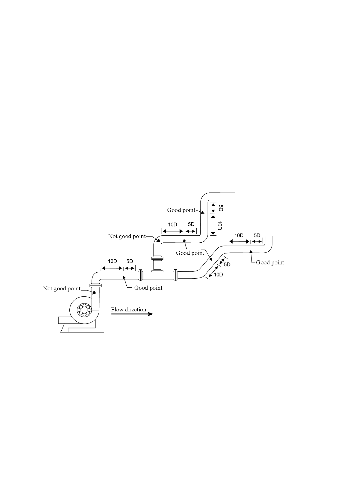
1. Pipe is uniform, full with a liquid and able to transmit the ultrasonic beam without interference (e.g.
a vertical (up-flow) or horizontal pipe – illustration below).
2. The upstream transducer should be installed at the place where the upstream length of the
straight pipe is at least 10D and the downstream length is at least 5D. To install the
downstream transducer, the pipe should be straight without any valve, pump, angle head or
pipe size changing within 15D length (D = pipe outside diameter) . The installation point
should be far from valves, pump or interference source, such as high-voltage electricity,
frequency transformers .
3. Avoid installing on the highest point of pipe or vertical pipe with free exit (flow down).
Page 15

13 of 21
4. For the opened pipe or half full pipe, the transducers should be installed on bottom of U pipe.
5. The temperature and pressure at the installation point should be in the work range of the
transducers.
6. Pay attention to the pipes inner wall and check for pollution build-up. Select a pipe without any or
very little buildup of sediment because it may interfere with the signal.
7. The two transducers must be installed in horizontal direction, within ±45°of horizontal plane to
prevent bubbles in pipe. The pipe should not be full or contain any sediment, which would affect
the precision of the measurement. If space is limited when installing, do not install the sensors
horizontally and symmetrically. Instead, install the transducers vertically or with dip angle. Then
the user must check and ensure no bubbles are found in the inner top of pipe.
Page 16
14 of 21
4.3.2 Installation R equirements for a Well
To install transducers in a well, there must be enough installation space so the engineer can install it
conveniently. The distance between pipe wall and well wall should be more than 550mm, the width is
more than (D+550*2) mm, the cement pipe width is more than (D+700*2) mm and the instrument well
axial width L is more than D+1200mm. When installing transducers, avoid the following places: flange,
welding line and changing diameters. It is best to install transducers in the range of +/-45° of horizontal
position of pipe axis.
Page 17

15 of 21
Attention!
1. Install transducers in the range of +/-45° of horizontal position of pipe axis.
2. Connect the mainframe shell with ground.
3. Avoid the installation places of flange, welding line, changing diameter.
4. Have enough installation room, convenient for people to stand up to work
4.4 Quick Pipe Parameter Setting
The user must set the parameters when measuring the following:
1. Pipe outer diameter
2. Pipe wall thickness
3. Pipe material
4. Liner parameter (if having liner, then the liner thickness and sound velocity)
5. Fluid types
6. Transducers type
7. Transducers installation method
8. Solidification parameter
4.5 Installing a Clamp Type Transducer
Before installing, start by cleaning the installation area; removing any rust, paint and anti-rust layers.
Then polish the area using a clean cloth with either alcohol or acetone. Apply a sufficient amount of
grease at the installation area and clamp the transducers tightly on the pipe. The grease is used to
eliminate any gaps between the transducer and the pipe wall. NOTE: If not enough grease is applied or
the transducers are not clamped to the wall tightly, the precision of measurement may be effected.
Page 18
16 of 21
High temperature S1H type High temperature M2H type
Standard S1 type Standard M2 type
Standard L1 type
Transducer
S1 type
M2 type
L1 type
S1H type
M2H type
Compliant pipe
size
DN15~100
DN50~700
DN300~6000
DN15~100
DN50~700
Fluid
temperature
0℃~70℃
0℃~70℃
0℃~70℃
0℃~160℃
0℃~160℃
size
45×30×30mm
60×45×45
80×70×55
90×85×24
90×82×29
weight
75g
250g
650g
94g
150g
4.5.1 Installation Space
The installation space for the clamping transducer is the nearest distance of the two transducers (please
refer to the sketch in 4.5.2). After setting the required parameters in the menu, go to the space figure at
M25.
4.5.2 Installation Methods: “V & Z Methods”
There are two types of installation methods to choose from: the “V Method” and the “Z Method”.
1. The “V Method” is the first choice when measuring a pipe with a diameter range of
DN15-DN200mm. If no signal is received or the signal is weak with V method, then use
the “Z Method”. The “V Method” is a standard installation method because it is
convenient to install and easy to ensure the installation precision of relative position
between two transducers. The horizontal median should be parallel with pipe axis line.
The V method can be used on pipe with DN15mm-DN400mm.
(Illustration below)
Page 19

17 of 21
3. The “Z Method” is the most commonly used method. When a pipe diameter is wide, there are
suspended matters in the fluid or are too thick or may have produced incrustation (or a liner)
causing the flow meter to not function properly or give a weak signal using the “V Method”. The
“Z Method” is then applied. The pulse reaches the other transducer with single sound path and
less signal attenuation.
PLEASE NOTE/IMPORTANT!
1. Before installing, the surface of the pipe being measured MUST be cleaned using either
alcohol or acetone and a clean cloth.
2. When connecting the transducer cable, it is acceptable that the shielded cable is not
connected. But do not connect them to the red or black line; this will cause the shielded
cable to short circuit.
3. After transducers are connected with cables, the user must seal the connecting point with
grease or a sealant to prevent water getting into the sensors.
4. After covering the transducers with grease, the user must screw and tightly lock the shield
line hole to prevent water getting in.
5. Fix the transducer with the strap (stainless steel band) at the middle of the transducer to
ensure it is tightly bound to the pipe.
6. Apply an ample amount of grease between the grease and the pipe to prevent bubbles, sand
or rust getting in
Page 20

18 of 21
4.6 Turning O n the FDT-21W
A self-diagnosis function runs every time the FDT-21W is powered on. If there are any issues/problems,
the errors are displayed on the upper right corner of the LCD (Please refer to Chapter 5 detailed). After
the diagnosis, the meter will work according to last parameter setting.
It does not affect the measurement when programming the unit because the meter is designed with
Time-Division techniques. Measurement, calculation, keypad operation, display, typing, inputting and
output are treated as “affair” and all affairs are independent.
For example, if we change the date and time, this operation would not affect the “affairs” which have no
relationship with date and time. After finishing the steps S1, S2, S3, S4 deployed on the left upper corner,
the meter will start the measurement and “R” will be displayed on the left upper corner.
If it is the first usage of the meter or a new installation point, you need to set the pipe parameters. The
meter will adjust and calculate automatically if you change the parameter setting. The meter will go to
the menu page when it is shut down.
4.7 Checking Transducer Installation
After the transducers have been completely installed, check the following: signal strength S, the signal
quality Q value, total time ratio, delta time and the transit time ratio to confirm the installation is completed.
Usually, a signal is available after putting grease on the transducer and securing it to the pipe, but
absolute confirmation all the checks listed above are essential in order to get reliable and accurate
measure results.
4.7.1 Signal Strength
The signal strength “S ” (display on M90) indicates the strength of the sending and receiving signals from
the upstream transducer and the downstream transducer. “[00.0]” indicates no signal detected and
“[99.9]” indicates the maximum and best signal strength that can be detected. While installing, if a signal
is not received or is weak, the positions of the transducers can be adjusted Along with adjusting the
transducers, adequately greasing them will enable the user to get the strongest signal.
The meter works well when the signal strength ranges from 60 to 99. When the signal strength is too
weak, recheck the installation position, transducer distance, if the pipe is suitable for installation or change
installation method.
4.7.2 Signal Quality (Q Value) :
Signal quality is indicated as the “ Q ” value (display on M90) which indicates either a good or poor/weak
signal. The FDT-21W series uses the “00-99” digits to represent signal quality. “00” represents the worst
signal and “99” represents the best signal. Ideally, the signal quality should be above “60”. When the Q
value is not meeting the ideal benchmark of “60”, there are a few reasons for this: interference, shoddy
installation of the transducers, the quality of the signal cables are inferior, not enough grease was applied
between the transducers and pipe or the position of the transducers needs adjusting.
4.7.3 Total Transit Time (Delta Time)
Page 21

19 of 21
The total transit time (delta time) is displayed on the menu window M93, which indicates if the installation
is correct. The flow meter’s internal measurement and calculation are based on these two parameters.
When the indicating delta time data fluctuates too much, the showed flow rate and velocity will change
quickly, too. In this case, it means the signal quality is not good; perhaps the pipe is not good enough for
measurement, is not suitable for the installation of the transducers or the wrong parameters were set.
Usually the fluctuation of delta time should be less than ±20, but when the pipe diameter is too small or
flow velocity is slow, the fluctuation of delta time may be higher.
4.7.4 Transit Time Ratio
The transit time ratio (displayed on M91) is usually used to check whether the transducer installation
space is sufficient. If the pipe parameters are correctly set and the transducers are installed properly, the
transit time ratio should be in the range of 100±3 %. When the ratio is beyond this range, check the
following:
1. The pipe’s parameter was set correctly. This includes the pipes outer diameter, the thickness
of the pipe, the material of pipe and the liner.
2. The actual installation space of the transducers is the same as or close to what shown in M25.
3. If the transducers were installed properly on the same axis plane of pipe.
4. The mounting location is in the best possible place. Also check: if the pipe I. D. is changing
the age of the pipe (too old?), if there is excessive incrustation, if the liner inside the pipe is
exceedingly thick, if the flow rate is very slow or if any bubbles, paint or rust got inside the pipe.
5. Interference from other sources around the flow meter.
4.7.5 Note the following points when installing
1. The pipe parameters must be correctly entered; otherwise the flow meter will not work
accurately.
2. When fixing the clamp to the transducers, enough grease must be applied between the
transducers and the pipe, the signal strength and quality are verified on the display screen while
moving one transducer around the installation point to get the best signal and signal quality; the
bigger the pipe size, the larger moving range. Then check the installation distance, ensure it is
the same with what displayed on M25. If the signal strength is “0.00”, it means no ultrasonic
beam. Then check whether the input parameters and the installation method are correct. Also
check the age of the pipe, the liner thickness, inside the pipe for bubbles, rust or paint. Confirm
there is fluid inside the pipe (must have full fluid). Other quality control checks: is the space is
too near to the valves, angle head? If any of these check points are not the reasons for a poor or
absence of a signal, try another measuring point.
3. After installation has finished, go to M26 to solidify the parameters, shut it down and power it on
again to check if the results are correct.
5. Troubleshooting
The FDT-21W was designed with and accurate self-diagnosis function. The errors are displayed on the
upper right corner of the LCD display via identification code in a timely order. All the existing errors can
be checked at M08. Hardware self-diagnosis is executed every time the meter is powered on and some
errors can even be detected when operating. For those errors undetectable due to incorrect settings or
improper testing conditions, the flow meter will display information to help the user to quickly debug the
Page 22
20 of 21
error and solve the problems according to following listed methods.
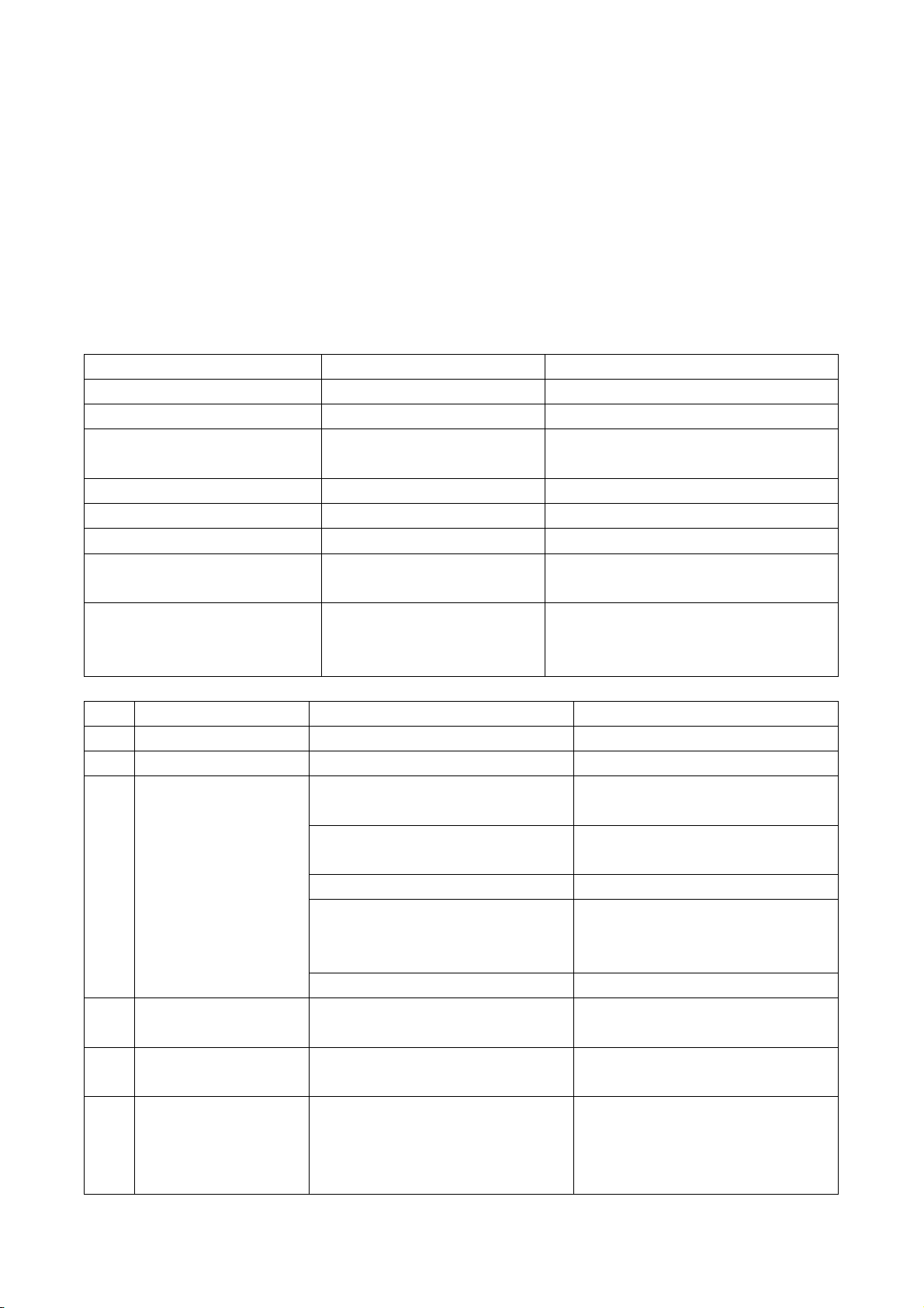
Displayed errors of FDT-21W are distinguished to two types:
1. Circuit hardware errors. Please refer to Table 1 of potential problems and solution methods.
Example: If “F” is displayed upon power on, restart the unit, check the solution table and follow
the instructions listed in the box. If the problem still exists, please contact OMEGA
Engineering.
2. Measurement errors: please refer to Table 2.
Table 1. Hardware Diagnosis: Errors and Solutions
LCD Display Information
Causes
Solution
ROM verification Error
ROM operation illegal / error
Contact OMEGA.
Save data logger reading error
Stored parameters are wrong
Power on again/contact OMEGA.
System data logger error
System stored data area has
error
Power on again/contact OMEGA.
Measuring circuit hardware error
Sub-CPU circuit vital error
Power on again/contact the OMEGA.
Cpu clock speed error
System timer has errors
Power on again/contact the OMEGA.
Date and time error
System date and time are wrong
Reset date and time
No Display (Erratic or Abnormal)
Operation
Wires not well connect with the
display
Check wiring connections. No influence on
measuring
No response to key pressing
Keypad is locked
Bad plug connection
Input pw to unlock keyboard or check
wiring connections. No influence on
measuring.
Table 2 Working Status Errors Code Causes and Solutions
Code
M08 displaying
causes
solutions
R
system work normally
System is normal
J Circuit Hardware Error
Hardware problem
Contact the OMEGA
I
No Signal
Unable to receive signal
Ensure the transducers and pipes are tightly
fixed and with enough grease between them
Not well contact or not enough couplant
between transducer and pipe surface
Polish the pipe surface and clean the pipe
surface (to remove the paint and rust).
Transducers installed improperly
Check original installation parameter settings
Incrustation in pipe wall is too thick
Clear the incrustation or replace it with new
pipe, or move to another proper measure
point to find a point with less incrustation.
New changed liner
Wait until the liner is solidified enough
H
low signal strength
1. Low signal
2. Causes are the same as with code “I”
Solutions are the same as code “I”
H
poor signal quality
1. Poor signal quality
2. Include above all causes
Include above all solutions
E
The current of current loop is
over 20mA (does not affect
the measurement if don’t
using current output, we can
1. 4-20mA current loop output is over 100%
2. Improper settings for current loop output
Check current loop settings on M56. or
check if the actual flow rate is too high.
Page 23

21 of 21
don’t handle it)
Q
Frequency Output is higher
than the set value (does not
affect the measurement if
don’t using current output,
we can don’t handle it)
1. Frequency output is over 120%
2. Improper settings of frequency output or
flow rate in pipe is too high.
Check frequency output settings (refer to
M66-M69) or check if the actual flow rate is
too high.
F
Listed in table 1
Find problems when powered on and
self-diagnosis
Power on again, check the information
shown on the screen and handle according
to table 1. If not resolved, contact the seller
Permanent hardware problems
Contact the OMEGA.
G
Adjusting Gain >S1
Adjusting Gain >S2
Adjusting Gain >S3
Adjusting Gain>S4
(displayed on M00, M01,
M02, M03)
These four steps mean that the meter is
preparing to make the gain adjusting. If it
stops at S1 or S2 or switching between S1
and S2, it means the signal is low or bad
wave
K
Empty Pipe, setup on M29.
No liquid in pipe or wrong setup.
If actually there is liquid in pipe, please
set 0 on M29
Attention: The codes of Q, & E displayed do not affect measurement. This only means the
current loop and frequency output have problems.
Page 24

WARRANTY/DISCLAIMER
OMEGA ENGINEERING, INC. warrants this unit to be free of defects in materials and workmanship for a
period of 13 months from date of purchase. OMEGA’s WARRANTY adds an additional one (1) month
grace period to the normal one (1) year product warranty to cover handling and shipping time. This
ensures that OMEGA’s customers receive maximum coverage on each product.
If the unit malfunctions, it must be returned to the factory for evaluation. OMEGA’s Customer Service
Department will issue an Authorized Return (AR) number immediately upon phone or written request.
Upon examination by OMEGA, if the unit is found to be defective, it will be repaired or replaced at no
charge. OMEGA’s WARRANTY does not apply to defects resulting from any action of the purchaser,
including but not limited to mishandling, improper interfacing, operation outside of design limits,
improper repair, or unauthorized modification. This WARRANTY is VOID if the unit shows evidence of
having been tampered with or shows evidence of having been damaged as a result of excessive corrosion;
or current, heat, moisture or vibration; improper specification; misapplication; misuse or other operating
conditions outside of OMEGA’s control. Components in which wear is not warranted, include but are not
limited to contact points, fuses, and triacs.
OMEGA is pleased to offer suggestions on the use of its various products. However,
OMEGA neither assumes responsibility for any omissions or errors nor assumes liability for any
damages that result from the use of its products in accordance with information provided by
OMEGA, either verbal or written. OMEGA warrants only that the parts manufactured by it will be
as spec ified and free of de f ects. OMEGA M AKES N O OTH ER WARRANTIES OR
REPRESENTATIONS OF ANY KIND WHATSOEVER, EXPRESS OR IMPLIED, EXCEPT THAT OF TITLE,
AND ALL IMPLIED WARRANTIES INCLUDING ANY WARRANTY OF MERCHANTABILITY AND
FI TNESS FOR A PARTICULAR PURPOSE ARE HEREBY DISCLAI MED. LIMITATION OF
LIABILITY: The remedies of purchaser set forth herein are exclusive, and the total liability of
OMEGA with respect to this order, whether based on contract, warranty, negligence,
indemnification, strict liability or otherwise, shall not exceed the purchase price of the
co mponent upon which liability i s base d. In n o even t shal l OMEG A be liable f or
consequential, incidental or special damages.
CONDITIONS: Equipment sold by OMEGA is not intended to be used, nor shall it be used: (1) as a “Basic
Component” under 10 CFR 21 (NRC), used in or with any nuclear installation or activity; or (2) in medical
applications or used on humans. Should any Product(s) be used in or with any nuclear installation or
activity, medical application, used on humans, or misused in any way, OMEGA assumes no responsibility
as set forth in our basic WARRANTY/ DISCLAIMER language, and, additionally, purchaser will indemnify
OMEGA and hold OMEGA harmless from any liability or damage whatsoever arising out of the use of the
Product(s) in such a manner.
RETURN REQUESTS/INQUIRIES
Direct all warranty and repair requests/inquiries to the OMEGA Customer Service Department. BEFORE
RETURNING ANY PRODUCT(S) TO OMEGA, PURCHASER MUST OBTAIN AN AUTHORIZED RETURN
(AR) NU M BE R FR O M OME G A’S CUS T OM E R SERVI C E DEPA RT M EN T ( I N ORDE R T O AV O ID
PROCESSING DELAYS). The assigned AR number should then be marked on the outside of the return
package and on any correspondence.
The purchaser is responsible for shipping charges, freight, insurance and proper packaging to prevent
breakage in transit.
FOR WARRANTY
following information available BEFORE
contacting OMEGA:
1. Purchase Order number under which the product
was PURCHASED,
2. Model and serial number of the product under
warranty, and
3. Repair instructions and/or specific problems
relative to the product.
OMEGA’s policy is to make running changes, not model changes, whenever an improvement is possible. This affords
our customers the latest in technology and engineering.
OMEGA is a registered trademark of OMEGA ENGINEERING, INC.
© Copyright 2013 OMEGA ENGINEERING, INC. All rights reserved. This document may not be copied, photocopied,
reproduced, translated, or reduced to any electronic medium or machine-readable form, in whole or in part, without the
prior written consent of OMEGA ENGINEERING, INC.
RETURNS, please have the
FOR NON-WARRANTY REPAIRS,
for current repair charges. Have the following
information available BEFORE contacting OMEGA:
1. Purchase Order number to cover the COST
of the repair,
2. Model and serial number of the product, and
3. Repair instructions and/or specific problems
relative to the product.
consult OMEGA
Page 25

Where Do I Find Everything I Need for
Process Measurement and Control?
OMEGA…Of Course!
Shop online at omega.com
sm
TEMPERATURE
䡺⻬
Thermocouple, RTD & Thermistor Probes, Connectors, Panels & Assemblies
䡺⻬
Wire: Thermocouple, RTD & Thermistor
䡺⻬
Calibrators & Ice Point References
䡺⻬
Recorders, Controllers & Process Monitors
䡺⻬
Infrared Pyrometers
PRESSURE, STRAIN AND FORCE
䡺⻬
Transducers & Strain Gages
䡺⻬
Load Cells & Pressure Gages
䡺⻬
Displacement Transducers
䡺⻬
Instrumentation & Accessories
FLOW/LEVEL
䡺⻬
Rotameters, Gas Mass Flowmeters & Flow Computers
䡺⻬
Air Velocity Indicators
䡺⻬
Turbine/Paddlewheel Systems
䡺⻬
Totalizers & Batch Controllers
pH/CONDUCTIVITY
䡺⻬
pH Electrodes, Testers & Accessories
䡺⻬
Benchtop/Laboratory Meters
䡺⻬
Controllers, Calibrators, Simulators & Pumps
䡺⻬
Industrial pH & Conductivity Equipment
DATA ACQUISITION
䡺⻬
Data Acquisition & Engineering Software
䡺⻬
Communications-Based Acquisition Systems
䡺⻬
Plug-in Cards for Apple, IBM & Compatibles
䡺⻬
Data Logging Systems
䡺⻬
Recorders, Printers & Plotters
HEATERS
䡺⻬
Heating Cable
䡺⻬
Cartridge & Strip Heaters
䡺⻬
Immersion & Band Heaters
䡺⻬
Flexible Heaters
䡺⻬
Laboratory Heaters
ENVIRONMENTAL
MONITORING AND CONTROL
䡺⻬
Metering & Control Instrumentation
䡺⻬
Refractometers
䡺⻬
Pumps & Tubing
䡺⻬
Air, Soil & Water Monitors
䡺⻬
Industrial Water & Wastewater Treatment
䡺⻬
pH, Conductivity & Dissolved Oxygen Instruments
M5233/0213
 Loading...