

Page 1

Company Headquarters: 1755 La Costa Meadows Drive, San Marcos, CA 92078-5115
DOCUMENT NUMBER
08EN000525
SUBJECT
FC88 Kit Instructions
CAGE CODE
64818
DATE
07-28-22
SECTION
PAGE
1 of 7
REVISION
C
Notice of proprietary rights: This document contains confidential and technical data, including trade secrets and proprietary information which
is the property of Fluid Components International LLC (FCI) pursuant to the proprietary rights on the first page of this document.
INTRODUCTION
General
1. This kit contains the parts necessary to connect the FC88 Control Display to the GF90/GF92,
AF88/AF89, ST95/ST96, ST98, ST50/ST51/ST75/ST75V, and ST51A/ST75A/ST75AV
instruments.
2. Connection instructions are given that show how to connect the FC88 to FCI’s instruments.
Ordering of Parts
Ordering of parts are to be directed as follows:
Fluid Components International LLC
1755 La Costa Meadows Drive
San Marcos, California 92078
Attention: Customer Sales
Phone: (800) 854-1993 or (760) 744-6950 or Fax: (760) 736-6250
www.fluidcomponents.com
Publication Requests
Requests for copies of publications should be directed to the address shown in the above
paragraph.
AF88/AF89 OPERATION
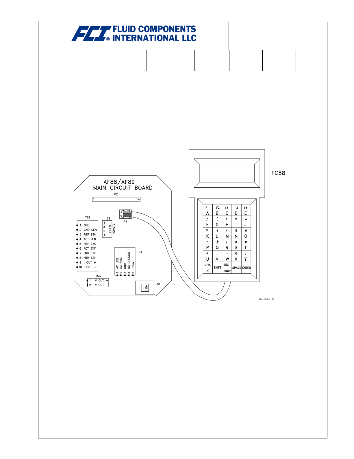
Plug the cable into the FC88 as shown in Figure 1. Plug the other end of the cable into P1 of the main
circuit board of the AF88 or AF89 as shown in Figure 1. If the FC88 will not be used in conjunction
with the FlexMASSter the adapter circuit board may be discarded. The FC88 is ready for use.
Using FC88 With Multiple Instrument Models
If an FC88 Control Display Unit has been used on a FlexMASSter instrument and it needs to be
used on an AF88 or AF89 instrument the FC88 will need to be reprogrammed. The following
instructions reprogram the FC88:
1. With the FC88 cable disconnected from the AF88/89, simultaneously press the CTRL, SHIFT,
and F1 keys.
2. While holding down all three keys pressed in Step 1, plug the FC88 cable into the energized
AF88/89.
3. A message should immediately come up on the screen of the FC88 as shown below.
LOAD DEFAULT DATA!
ARE YOU SURE?
YES NO
Page 2
Company Headquarters: 1755 La Costa Meadows Drive, San Marcos, CA 92078-5115
DOCUMENT NUMBER
08EN000525
SUBJECT
FC88 Kit Instructions
CAGE CODE
64818
DATE
07-28-22
SECTION
PAGE
2 of 7
REVISION
C
Notice of proprietary rights: This document contains confidential and technical data, including trade secrets and proprietary information which
is the property of Fluid Components International LLC (FCI) pursuant to the proprietary rights on the first page of this document.
4. Press the “A” (YES) key on the FC88. Wait for the FC88 to beep.
5. Press the following keys in sequence (not simultaneously): SHIFT, CTRL, SPACE.
6. Press the “A” key until “9600 BAUD” appears on the screen. Press the “E” key to save.
7. Press the “A” key until “PARITY=SPACE” appears on the screen. Press the “E” key to save.
8. The screen should now read “32 CHARACTER DISPLAY”. Press “E” to save.
9. The set-up is complete. If the FC88 is plugged into a working AF88/89 the FC88 should now
be operating in its normal mode with the instrument.
Figure 1
Page 3
Company Headquarters: 1755 La Costa Meadows Drive, San Marcos, CA 92078-5115
DOCUMENT NUMBER
08EN000525
SUBJECT
FC88 Kit Instructions
CAGE CODE
64818
DATE
07-28-22
SECTION
PAGE
3 of 7
REVISION
C
Notice of proprietary rights: This document contains confidential and technical data, including trade secrets and proprietary information which
is the property of Fluid Components International LLC (FCI) pursuant to the proprietary rights on the first page of this document.
GF90/GF92 OPERATION
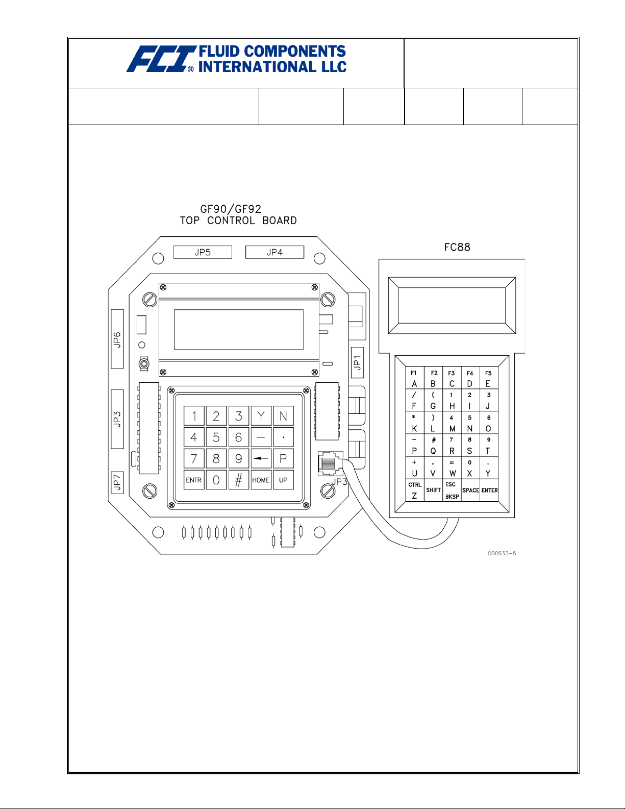
Plug the cable into the FC88 as shown in Figure 2. Plug the other end of the cable into JP3 of the top
control board of the GF90 or GF92 as shown in Figure 2. If the FC88 will not be used in conjunction
with the FlexMASSter the adapter circuit board may be discarded. The FC88 is ready for use.
Figure 2
Page 4
Company Headquarters: 1755 La Costa Meadows Drive, San Marcos, CA 92078-5115
DOCUMENT NUMBER
08EN000525
SUBJECT
FC88 Kit Instructions
CAGE CODE
64818
DATE
07-28-22
SECTION
PAGE
4 of 7
REVISION
C
Notice of proprietary rights: This document contains confidential and technical data, including trade secrets and proprietary information which
is the property of Fluid Components International LLC (FCI) pursuant to the proprietary rights on the first page of this document.
FLEXMASSTER OPERATION
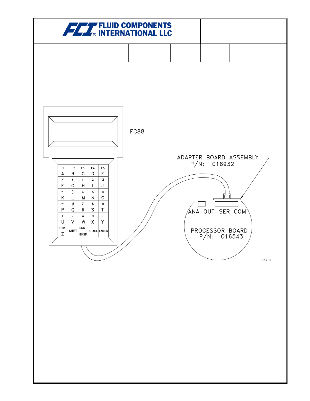
Plug the cable into the FC88 as shown in Figure 3. Plug the other end of the cable into the P1 of
the adapter circuit board Part Number 016932. Plug P2 of the adapter circuit board into the serial
communication connector of the processor board of the FlexMASSter instrument as shown in
Figure 3. The FC88 is ready for use.
Figure 3
Page 5
Company Headquarters: 1755 La Costa Meadows Drive, San Marcos, CA 92078-5115
DOCUMENT NUMBER
08EN000525
SUBJECT
FC88 Kit Instructions
CAGE CODE
64818
DATE
07-28-22
SECTION
PAGE
5 of 7
REVISION
C
Notice of proprietary rights: This document contains confidential and technical data, including trade secrets and proprietary information which
is the property of Fluid Components International LLC (FCI) pursuant to the proprietary rights on the first page of this document.
ST98 OPERATION
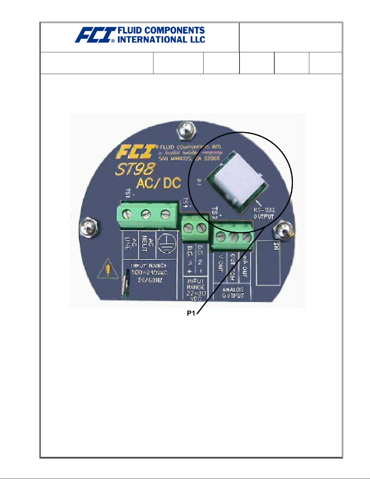
Plug the cable into the FC88. Plug the other end of the cable into P1 of the Customer Connection
Board inside of the ST98 instrument (pictured in Figure 4). The FC88 is ready for use.
Figure 4
Page 6
Company Headquarters: 1755 La Costa Meadows Drive, San Marcos, CA 92078-5115
DOCUMENT NUMBER
08EN000525
SUBJECT
FC88 Kit Instructions
CAGE CODE
64818
DATE
07-28-22
SECTION
PAGE
6 of 7
REVISION
C
Notice of proprietary rights: This document contains confidential and technical data, including trade secrets and proprietary information which
is the property of Fluid Components International LLC (FCI) pursuant to the proprietary rights on the first page of this document.
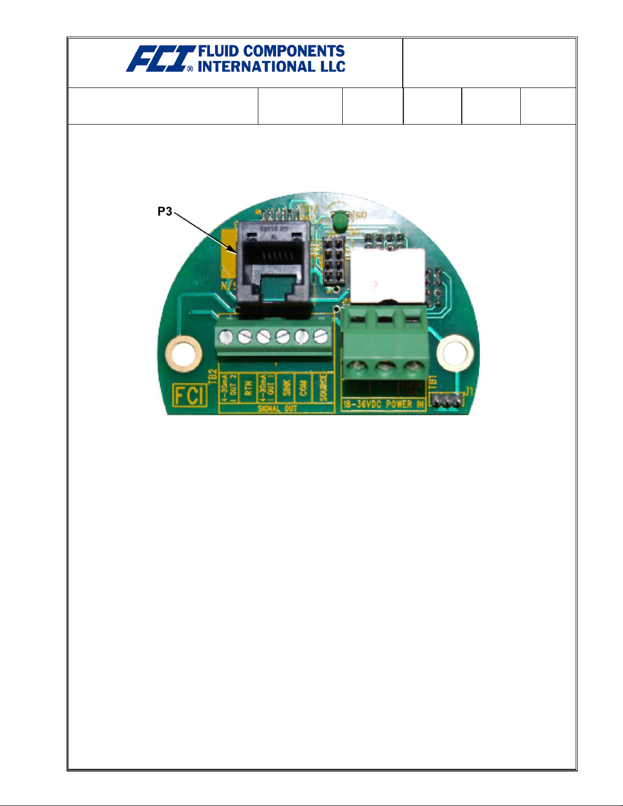
ST50, ST51, ST75 (GEN1) OPERATION
Plug the cable into the FC88. Plug the other end of the cable into P3 of Customer Connection Board
inside of the ST50, ST51 or ST75 instrument (pictured in Figure 5). The FC88 is ready for use.
Figure 5
Page 7
Company Headquarters: 1755 La Costa Meadows Drive, San Marcos, CA 92078-5115
DOCUMENT NUMBER
08EN000525
SUBJECT
FC88 Kit Instructions
CAGE CODE
64818
DATE
07-28-22
SECTION
PAGE
7 of 7
REVISION
C
Notice of proprietary rights: This document contains confidential and technical data, including trade secrets and proprietary information which
is the property of Fluid Components International LLC (FCI) pursuant to the proprietary rights on the first page of this document.
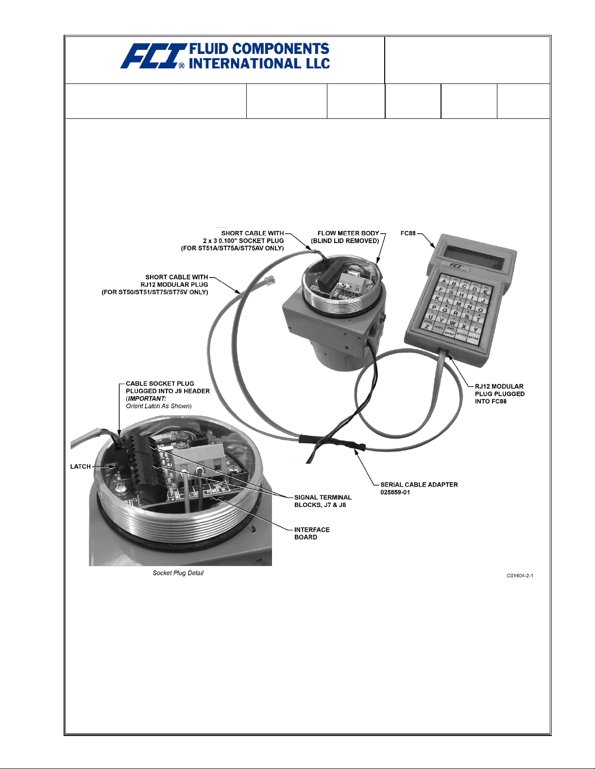
ST51A, ST75A, ST75AV (GEN3) OPERATION
An RS-232 serial port is provided via a .100″ 2 x 3 header connector (J9) on the interface board
(remove blind lid for access). Plug the serial cable adapter assembly 025859-01 onto the J9 header
as shown in Figure 6 below (make sure the connector latch is oriented as shown). Then plug the
other end of the cable (the longer of the two modular connector cable ends) into the FC88 handheld
calibrator. Note that the 025859-01 cable has a dual purpose—the other (unused) short cable end
with the modular plug is for connecting a Gen1 (ST50, ST51, ST75, ST75V) instrument to the FC88.
Figure 6
 Loading...