

Page 1
ST75/ST75V MASS FLOW METER
C00568-3-1
Installation and Operation Guide
Pre-Installation
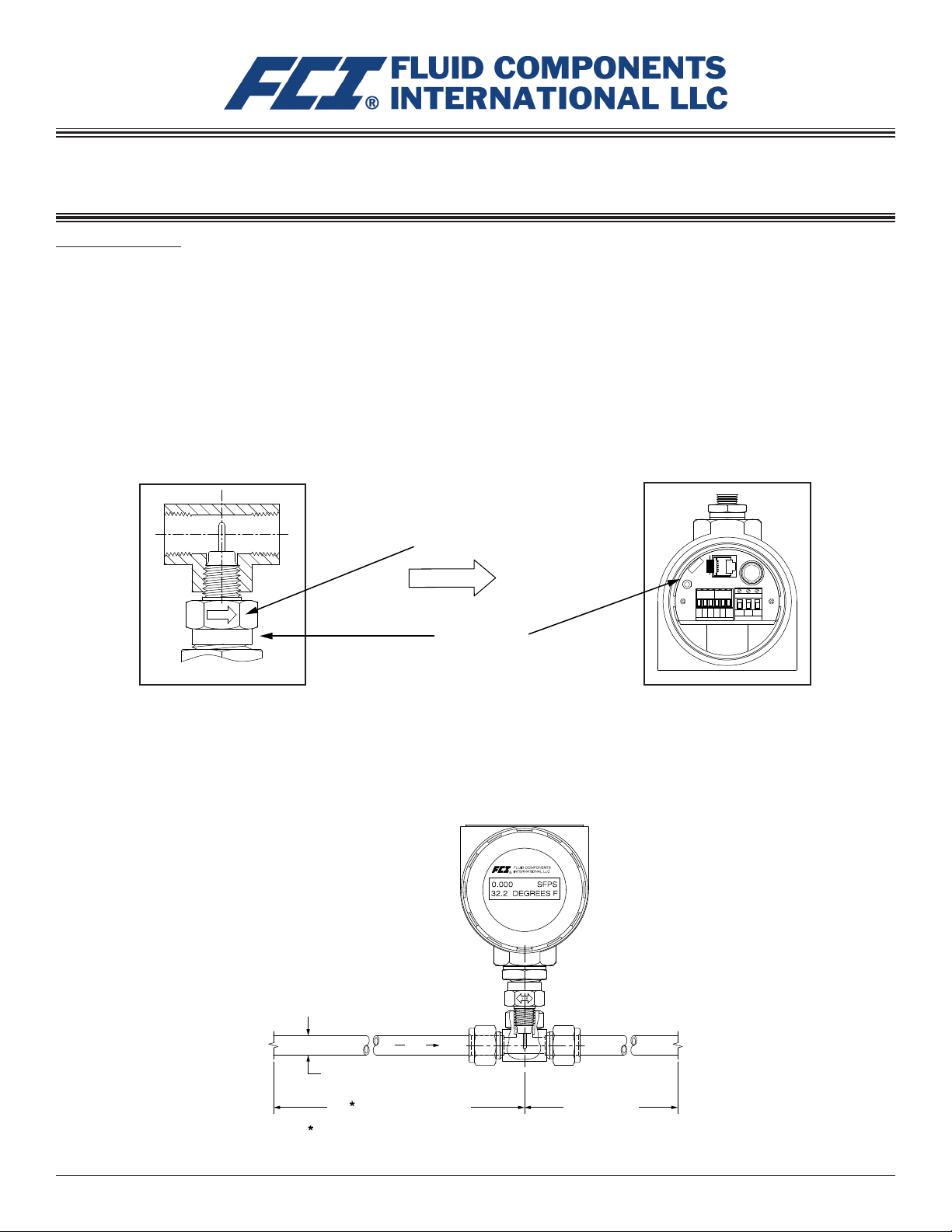
Serial Number Alignment
The ST75 and ST75V (Vortab) can be specied with integral or remote electronics. The ow element has a serial number etched into the side
of the HEX as shown on Figure A. In addition, the enclosure tag also shows serial and model numbers. The associated transmitter circuit card
has a serial number noted on the board as shown in Figure B. The ow sensor and transmitter circuit have been calibrated as a matched set
and should be paired together in service unless otherwise approved by a factory technician.
Flow Direction Alignment
All sensor elements have a ow arrow indicator marked on the element assembly at the reference HEX at. These ow elements have been
calibrated in a particular direction and are designed to be used in service with the ow arrow going in the same direction as ow in the pipe
stream. The ow element has been calibrated directly in the pipe tee or tube tee with careful consideration for orientation and insertion depth.
Removal from the tee section while physically possible is not recommended unless authorized by a factory technician.
FLOW
247331
Figure A
Flow Direction
FLOW
Serial Number
C00570-1
247331
S/N
FCI
ON
TB2
4-20mA
Figure B
RTN
P3
SIGNAL OUT
FC88/CLI
F1
(TR5,
1.6A,
SB, UL)
TB1
EARTH
+
-
GND
SINK
COM
4-20mA
SOURCE
18-36VDC POWER IN
C00938-1
Recommended Straight Run
To optimize ow meter system performance, FCI recommends installation with a minimum of 20 diameters upstream straight run and 10 pipe
diameters of downstream straight run. Where straight run limitations signicantly reduce the available pipe diameters, FCI uses ow conditioners to produce a transferable ow prole from the calibration installation to actual eld installations. FCI’s proprietary AVAL software is
available to make ow meter installation evaluations where straight run limitations are considered. See Figure C for recommended installation.
This page is subject to proprietary rights statement on last page
FLOW
DIAMETER
AT LEAST 20 DIAMETERS
AFTER LAST FLOW DISTURBANCE
OPTIMUM CONDITION
10 DIAMETERS
BEFORE NEXT
FLOW DISTURBANCE
Figure C - Recommended Straight Run Condition
1
06EN003368 Rev. H
Page 2
Fluid Components International LLC ST75/ST75V Mass Flow Meter
Specications
Media Compatibility: Air, compressed air, nitrogen, oxygen, argon,
CO2, ozone, other inert gases, natural gas, and other hydrocarbon
gases, hydrogen.
Pipe/Line Size Compatibility: 1/4″ to 2″ [6 mm to 51 mm]
Instrument
ST75/ST75V Range:*
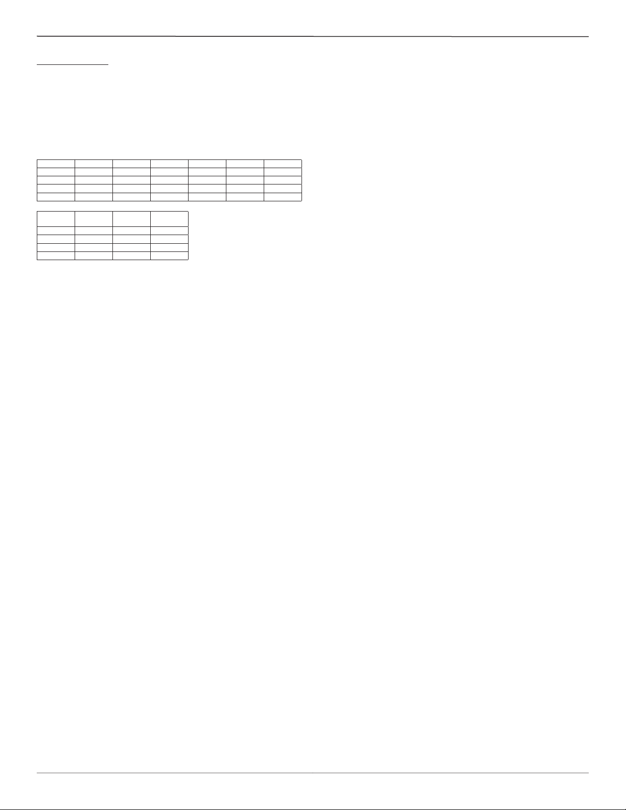
NPT Line Size ¼″ ½″ ¾″ 1″ 1½″ 2″
Min SCFM 0.04 0.13 0.22 0.35 0.85 1.40
Min [NCMH] [0,07] [0,22] [0,38] [0,59] [1,44] [2,38]
Max SCFM 17.34 50.64 88.88 139.95 539.31 559.27
Max [NCMH] [29,47] [86,04] [151,00] [237,78] [576,48] [950,20]
Tubing
Line Size
Min SCFM 0.01 0.05 0.25
Min [NCMH] [0,01] [0,09] [0,42]
Max SCFM 3.02 21.15 99.08
Max [NCMH] [5,14] [35,94] [168,33]
¼″ ½″ 1″
* Actual range subject to gas type and specic conditions.
Accuracy:
ST75: ±2% of reading, ±0.5% of full scale
Optional: ±1% of reading, ±0.5% of full scale
ST75V: ±1% of reading, ±0.5% of full scale
Repeatability:
± 0.5% of reading
Temperature Compensation:
Standard: 40 to 100 °F [4 to 38 °C]
Optional: 0 to 250 °F [-18 to 121 °C]
Turndown Ratio: 10:1 to 100:1
Agency Approvals:
ATEX/IECEx: II 2 G Ex db IIC T6...T1 Gb
II 2 D Ex tb IIIC T85°C...T300°C Db; IP66/IP67
Ta = -40°C to +65°C
FM, FMc: Class I, Div 1, Groups B, C, D
Class I, Div 2, Groups A, B, C, D
Class II/III Div 1, Groups E, F, G
Type 4X, IP66
CRN No.: 0F0303
Warranty:
One Year
Flow Element
Installation:
Material of Construction:
with Hastelloy-C thermowells; 316L stainless steel NPT, tube ttings,
and anges.
Maximum Operating Pressure:
ST75: Pipe Tee [NPT female]: 240 psi [16.5 bar(g)]
Tube Tee: 600 psi [41 bar(g)]
ST75V: 600 psi [41 bar(g)]
Temperature:
Process Connection:
ST75: Pipe Tee [NPT female]: 1/4″, 1/2″, 3/4″, 1″, 1 1/2″ or 2″
Tube Tee: 1/4″, 1/2″ or 1″
ST75V: Female NPT, Male NPT, Flange
1/4″, 1/2″, 3/4″, 1″, 1 1/2″ or 2″
In-line Tee or Spool.
All-welded 316L stainless steel ow element
Operating: 0 to 250 °F [-18 to 121 °C]
Transmitter
Enclosure:
either 1/2″ Female NPT or M20x1.5 entries. Polyester powder coated.
Output Signals:
(2) 4-20 mA user assignable to ow rate and/or temperature
(1) 0-500 Hz pulse for total ow
Communication Port:
Input Power:
DC: 18 VDC to 36 VDC (9.6 watts)
AC: 85 VAC to 265 VAC (10 watts)
Operating Temperature Range:
Digital Display
measured value and engineering units. Top line assigned to ow rate.
Second line is user assignable to temperature reading, ow totalizer
or alternating. Display can be rotated in 90° increments for optimum
viewing orientation.
NEMA 4X [IP67], aluminum, dual conduit ports with
RS232C standard.
0 to 140 °F [-18 to 60 °C]
(Optional): Two-line x 16 characters LCD. Displays
This page is subject to proprietary rights statement on last page
2
06EN003368 Rev. H
Page 3

ST75/ST75V Mass Flow Meter Fluid Components International LLC
FCI ow meters may be installed with less than the recommended straight run, but at the risk of limiting performance. FCI offers VORTAB
ow conditioners for use in applications that have signicant straight run limitations. FCI uses the AVAL application modeling software to
predict meter performance in each installation. AVAL outputs are available to review prior to order placement and will indicate performance
expectations both with and without ow conditioning.
Flow Element Installation
Caution: The element is shipped installed in the tee, with the element specically oriented for inline installation. Do not remove
the sensing element from the tee section during installation as calibration can be adversely affected.
Process Connections
The ST75 is available in pipe tee congurations with NPT threads and tubing tees with a compression tting suitable to clamp down on concentric smooth surface tubing. The pipe tee versions are standard 150# class rated tees suitable for service up to 150 PSIG at the process temperature maximum of 250 °F (121 °C). The compression tting material offered in the tube type conguration is rated for 250 PSIG service.
Pipe Tee Installation: With pipe extensions properly cut to length and the appropriate sealing materials used on the threads, install ow
element section by slowly rotating the conguration until rmly secure on the pipe section. Complete by installing opposing end pipe section
using care to rmly secure the element assembly either in a top mount or side mount position.
Tube Tee Installation: Clean all mating surfaces of the tee tting, ferrules and the ow tube. Insert the ow tubing into the tee tting. Make
sure the tubing rests rmly in the tting counter bore seat. Tighten the nut on both ends of the tee by hand. Hold the tting body steady with a
backup wrench, tighten the tting nuts 1-1/4 turns, from hand tight baseline.
The ST75V is available in with ow tube congurations offering male and female NPT threads, ANSI anges and DIN anges. The ow tube
assemblies are rated for service up to 240 PSIG at the process temperature maximum of 250 °F (121 °C).
NPT Flow Tube Installation: With pipe extensions properly cut to length and the appropriate sealing materials used on the threads, install ow
element section by slowly rotating the conguration until rmly secure on the pipe section. Complete by installing opposing end pipe section
using care to rmly secure the element assembly either in a top mount or side mount position.
Flanged Installation: Clean all mating surfaces. Install appropriate sealing gasket between mating anges. Tighten ange mating hardware to
meet system sealing requiments.
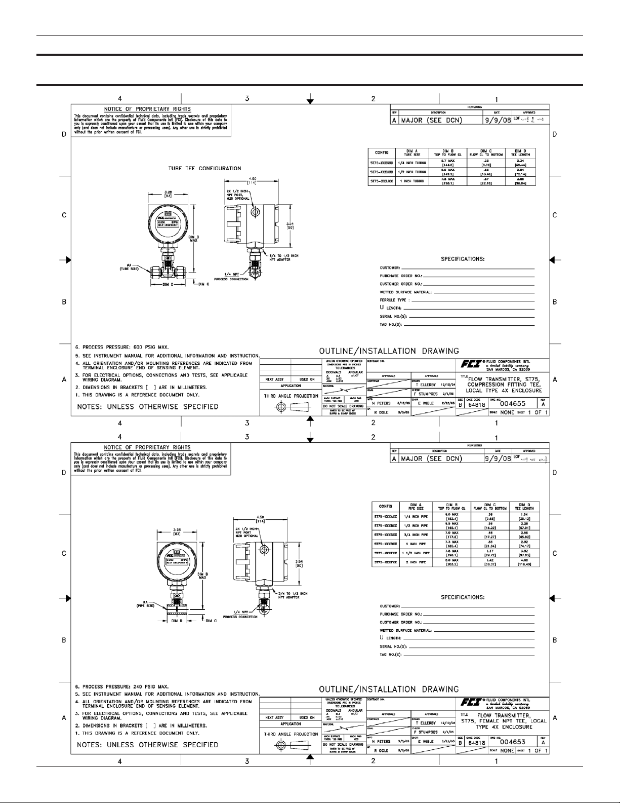
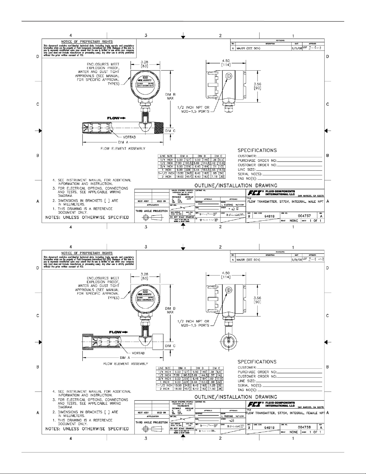
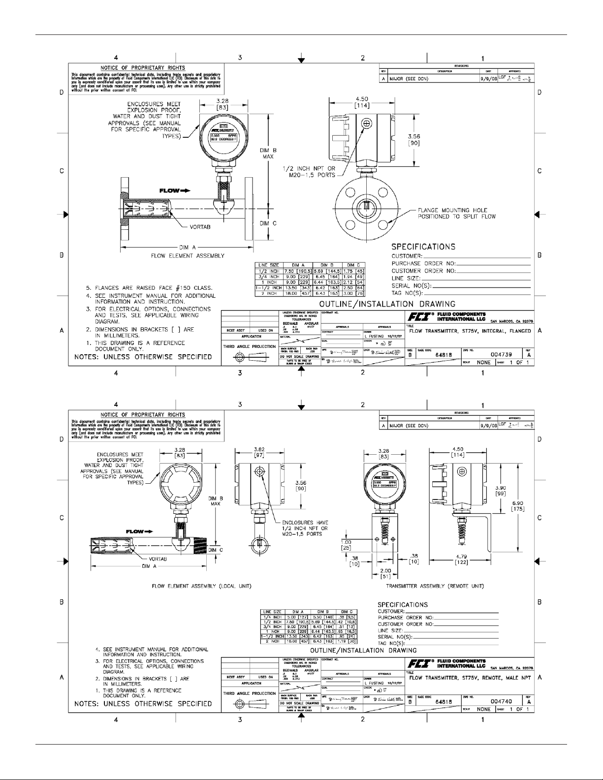
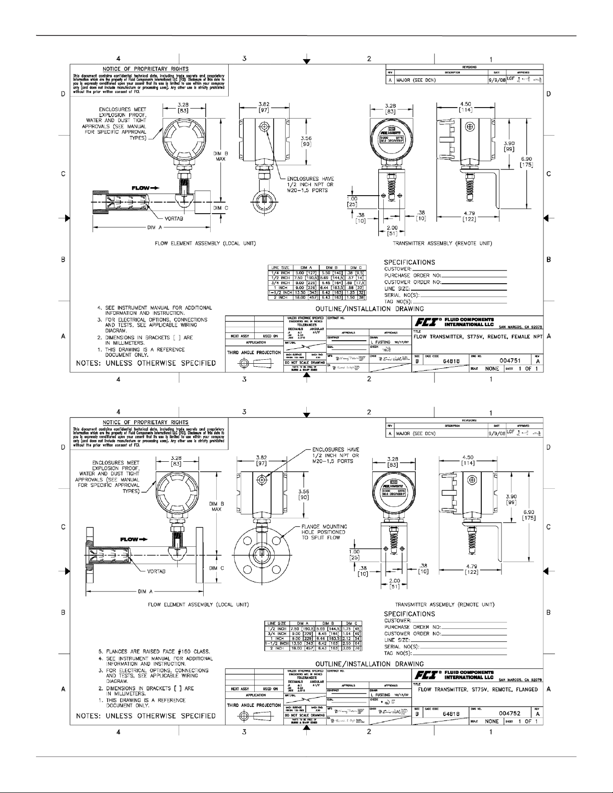
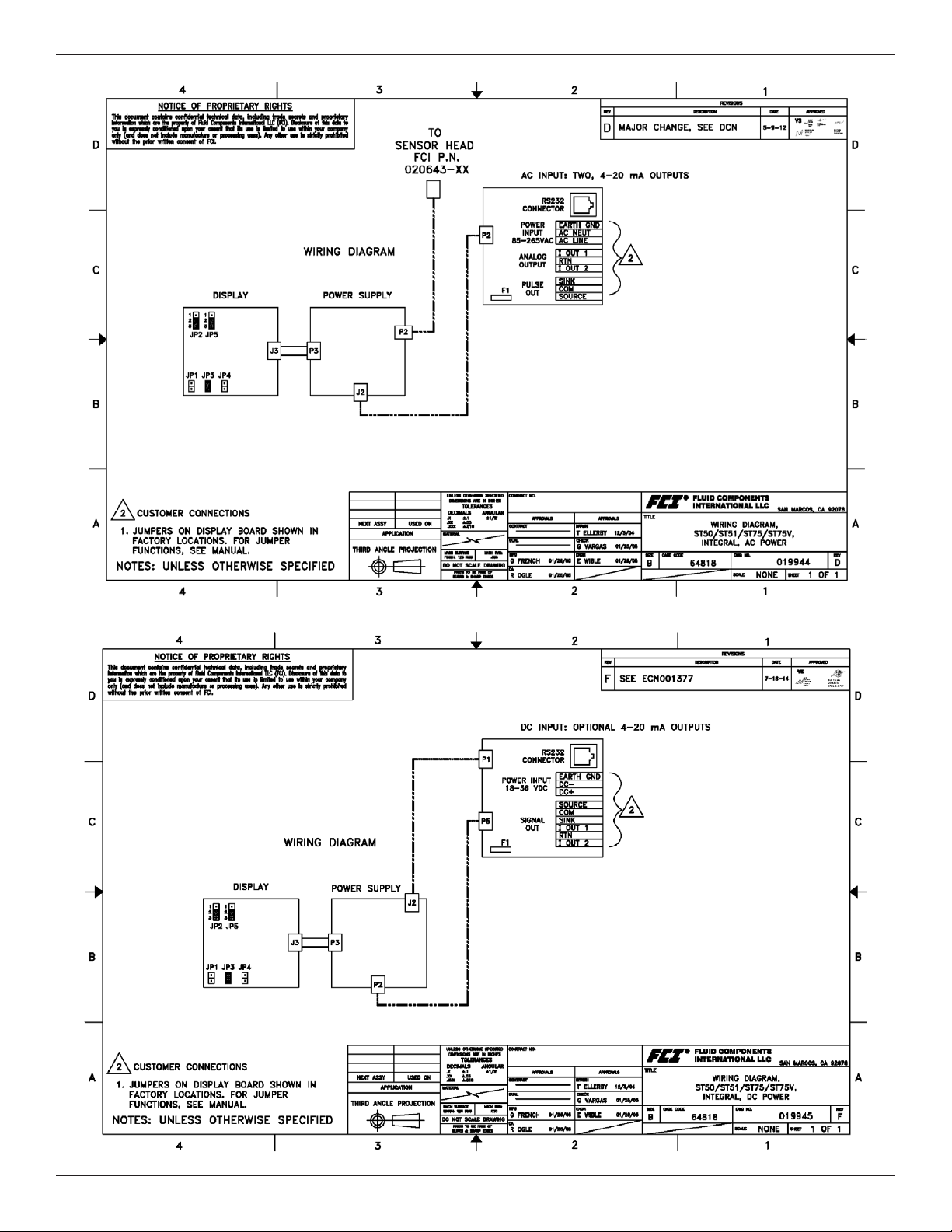
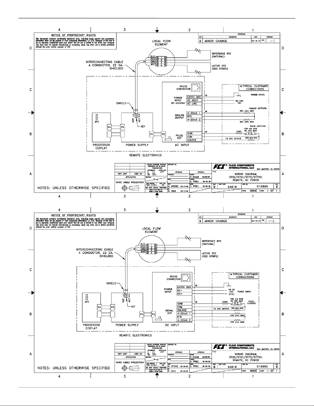
See Appendix C for instrument outline dimensional details.
This page is subject to proprietary rights statement on last page
3
06EN003368 Rev. H
Page 4

Fluid Components International LLC ST75/ST75V Mass Flow Meter
Instrument Wiring
Before opening the instrument to connect power and signal observe the following ESD precautions:
Use a wrist band or heel strap with a 1 megohm resistor connected to ground. If the instrument is in the shop setting, use a static conductive
mat on the work table or oor with a 1 megohm resistor connected to ground. Connect the instrument to ground. Apply antistatic agents such
as Static Free made by Chemtronics (or equivalent) to hand tools to be used on the instrument. Keep high static producing items away from
the instrument.
The above precautions are minimum requirements. The complete use of ESD precautions can be found in the U.S. Dept. of Defense Handbook 263.
Warning: Only qualied personnel are to wire or test this instrument. The operator assumes all responsibility for safe practices
while wiring and troubleshooting.
Install an input power disconnect
switch and fuse near the instrument to interrupt power during installation and maintenance.
Operator must have power disconnected before wiring.
See the “Specic Conditions of Use” and “Safety Instructions” sections in Appendix A for use of the ST75/ST75V (AC and DC
versions) in Hazardous Areas Category II (Zone 1).
Input Power
The ST75/ST75V is available with both VDC and VAC input power congurations. Customers selecting VDC input power will have a VDC
input board only. Similarly, the VAC power board is supplied only with VAC powered units. In addition, both boards are marked for either
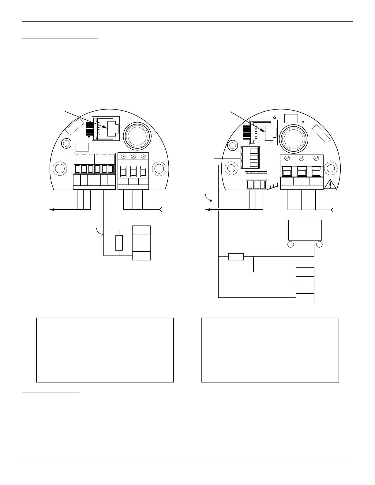
AC or DC power. Only connect the power specied on the wiring module as shown on Figures D and E respectively. Both VAC and VDC
inputs require a Gnd wire to be connected. Input power terminal blocks accept 14-26 AWG wire.
Make sure that power is OFF before wiring the instrument. Pull the power and signal output wires through the port, using care not to damage
wires. FCI recommends using crimp lugs on the output wires to ensure proper connection with the terminal strip. Connect the output wires as
shown on Figures D and E. Note that when the 4-20 mA outputs are used simultaneously, a single return lead is used.
Analog Output
4-20 mA: The instrument is provided with two 4-20 mA outputs. By default Output 1 is congured for ow and Output 2 is congured for
temperature. Terminal blocks accept 14-28 AWG wire, 500 ohms max load per output.
This page is subject to proprietary rights statement on last page
4
06EN003368 Rev. H
Page 5
ST75/ST75V Mass Flow Meter Fluid Components International LLC
Pulse Output Activation
The ST75/ST75V provides a pulse output feature. Instruments ordered with volumetric or mass ow units are factory set with totalizer and
pulse output activated. The mode can be changed in the eld. Source and sink output wiring is shown in Figures D and E below. Though only
one conguration is shown with the VAC and VDC power supplies, the source or sink can be used with either power input.
Sink Mode: 40 VDC max., 150 mA max. Customer-supplied power source.
Source Mode: 15 VDC output, 50 mA max.
RS-232
Connection
ON
C01440-1-1
VDC Power Connection
FC88/CLI
P3
S/N
FCI
TB2
I OUT 2
4-20mA
RTN
I OUT 1
4-20mA
SIGNAL OUT
Source
Output
SINK
COM
+
SOURCE
18-36VDC POWER IN
Counter Input
10 KΩ
VAC Power Connection
RS-232
F1
(TR5,
1.6A,
SB, UL)
TB1
EARTH
-
GND
DC POWER IN4-20 mA OUTS
Connection
Sink
Output
ON
PULSE
OUT
ANALOG
TB2
OUT
IN
COM
10 KΩ
TB3
FC88/CLI
P3
SOURCE
COM
SINK
4-20mA
RTN
4-20mA
FCI
AC
LINE
85-265VAC
AC
NEUT
AC POWER IN4-20 mA OUTS
S/N
F1
(TR5, 250V
1.6A, SB, UL)
EARTH
GND
POWER IN
TB1
Ext. 24-40 VDC
Power Supply
150 mA Max.
–
Counter Input
+
IN
Figure D
VDC Power
As Shown:
18-36 VDC power connected with Gnd
4-20 mA connected for ow and temperature
Pulse Out in source mode
Note: In source mode, 15 VDC output max., 50 mA max.
Power Dissipation
DC Version
Power dissipation values under nominal conditions:
Instrument (Electronics + Sensor): 4.5 watts
Sensor only: 0.25 watts
Power dissipation values under maximum load conditions:
Instrument (Electronics + Sensor): 6 watts
Sensor only: 0.30 watts
This page is subject to proprietary rights statement on last page
COM
Figure E
VAC Power
As Shown:
85-265 VAC power connected with Gnd
4-20 mA connected for ow and temperature
Pulse Out in sink mode
Note: In sink mode, 40 VDC max., 150 mA max. customersupplied power source.
AC Version
Power dissipation values under nominal conditions:
Instrument (Electronics + Sensor): 11.6 watts
Sensor only: 0.25 watts
Power dissipation values under maximum load conditions:
Instrument (Electronics + Sensor): 12 watts
Sensor only: 0.30 watts
5
C01441-1-1
06EN003368 Rev. H
Page 6
Fluid Components International LLC ST75/ST75V Mass Flow Meter
Setup Interface
All parameters on this meter are set through the RS232 interface connection (P3 plug). The RS232 interface allows the instrument to be set
up with either an FC88 hand held communicator or a computer. The FC88 is powered through the meter and comes with the serial interface
cable. If a computer interface is used, an adapter (RJ to 9-pin PC serial port) is required. The adapter can be obtained from FCI: Part No.
014108-02.
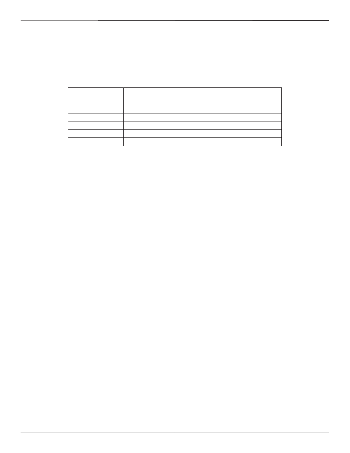
Using a serial comm/terminal program (e.g., HyperTerminal, TeraTerm, Putty, etc.) congure the PC’s serial port (the one intended to be
connected to the instrument) as listed in the table below.
COM Port Number:
Baud Rate:
Number of Bits:
Stop Bits:
Parity:
Flow Control:
Terminal Emulation:
Number of COM port connected to instrument (COM1, COM2, etc.)
9600
8
1
None
None
VT100
After conguring the serial port (and making the PC-to-instrument connections) start a communications session with the applicable serial
port. Enter any of the meter’s single letter commands in the program’s terminal window to execute a function. See “Table 5. ST75/ST75V
List of Single Letter Commands” on page 23 (Appendix B) for the complete command list.
An additional command line interface (CLI) is available through the RS232 port. This interface is accessed with the “Y” command using a
computer or FC88. The command line password is “357”. See “Table 6. ST75/ST75V List of CLI Commands” on page 23 (Appendix B)
for command line details.
This page is subject to proprietary rights statement on last page
6
06EN003368 Rev. H
Page 7
ST75/ST75V Mass Flow Meter Fluid Components International LLC
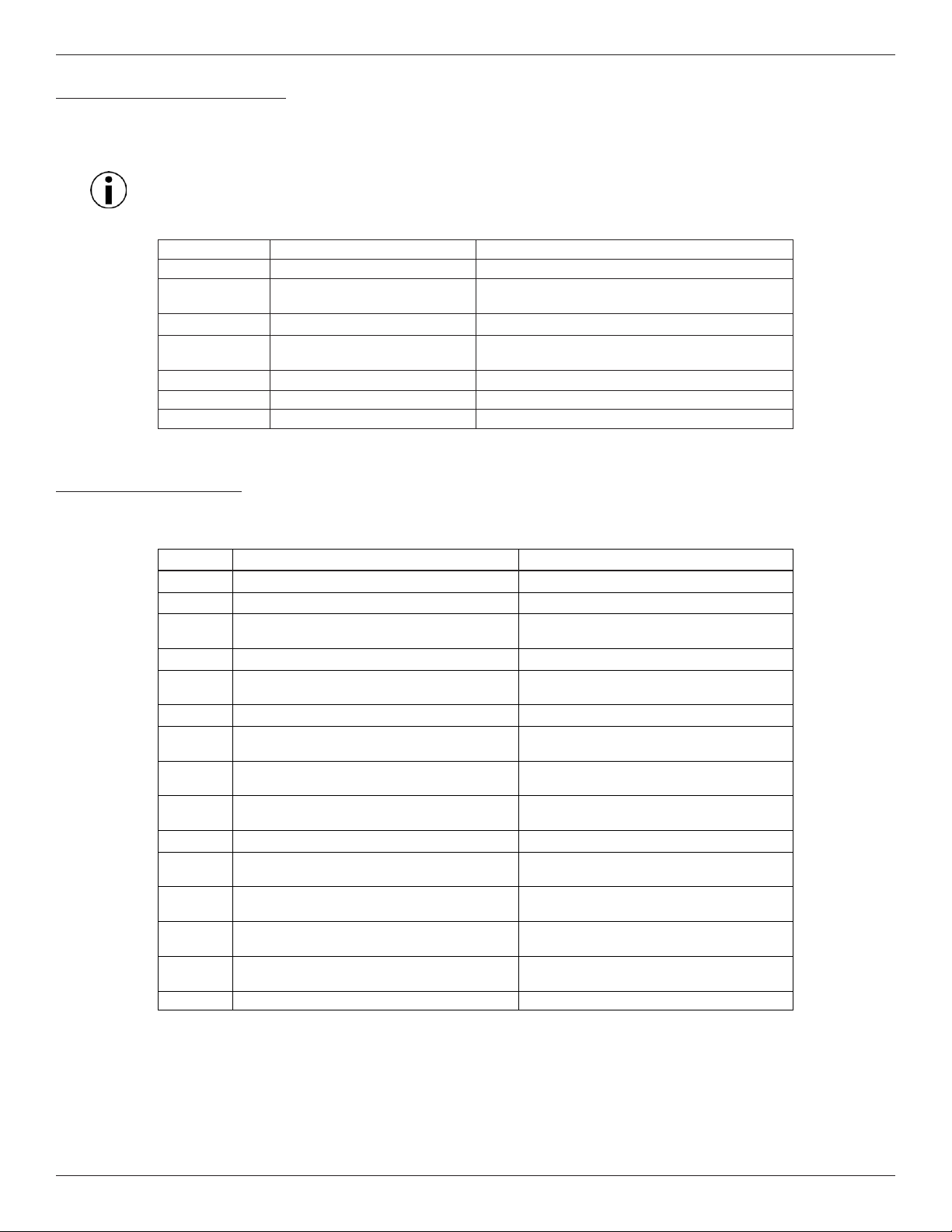
Start-up and Commissioning
1. Verify all input power and output signal wiring is correct and ready for initial power start-up.
Apply power to the instrument. The instrument initializes in the Normal Operation Mode with all outputs active. An instrument with the
2.
display option indicates ow with the factory-set ow units. Allow 10 minutes for the instrument to warm up and reach thermal equilibrium.
Note: Thirty (30) second warm-up required before calibration check.
The following FC88 commands are typical commands that are used during start-up and commissioning:
Command Name Description
T Normal Operation Mode All outputs are active
Z Flow Unit Set-up Select Flow Units (4 English, 4 Metric) Pipe Di-
mensions
W Totalizer Enable/Disable
V Output Conguration Select one of 4 Congurations: Pulse and/or Alarm-
Pulse factor and/or setpoint
F K-Factor (default = 1) Flow factor
N Warm Reset Re-initialize C/B
S Totalizer Menu Enables W menu (Option)
When placed in service, the instrument indicates 0.000 for no process ow.
Flow Unit Modication
Example: SCFM Flow Units and 3 inch Sch 40 round pipe size set up:
Enter
Dis
pla
y Descriptio
n
Enter menu: > From Normal Operation Mode
Z
E 0=SFPS, 1=SCFM, 2=SCFH, 3=LB/H,
E for English M for Metric > Flow Unit Set-Up menu
English units
4=GPM #
1
R
R round duct or S rectangular> Select standard cubic ft./minute (SCFM)
Dia.: 4.0260000
Select Round Duct
Change? (Y/N)>
Y Enter value: #
3.068 area: 7.3926572 CMinow: 0.0000000
Change? (Y/N
)>
3 inch Sch. 40 pipe I.D.
N Maximum ow: 462.04
Enter to
continue
Y Cmaxow: 462.04
Change? (Y/N
Y
#
)>
462.04 CMintemp (F): -40.00000
Change? (Y/N)>
N CMaxtemp (F): 250.00000
Change? (Y/N
)>
N Percent of Range is: OFF
Change to
ON?>
N LCD Mult Factor x1
Change? (Y/N
)>
N 100.0 SCFM Instrument ends up in Normal Operation Mode
This page is subject to proprietary rights statement on last page
7
06EN003368 Rev. H
Page 8
Fluid Components International LLC ST75/ST75V Mass Flow Meter
RS232 / FC88
Menu Control and Organization
Most entries require at least two keystrokes; a capital letter and the [ENTER] key, or one or more numbers and the [ENTER] key. All user
entries begin at the input mode prompt “>”, except when the instrument is in the Main Function Mode (just press the desired function letter
and [ENTER] to make an entry).
Backspaces are made using the backspace [BKSP] key. Some entries are case sensitive between numbers and letters. Be sure the SHIFT key
is pressed to indicate the correct case. A square after the prompt caret indicates the FC88 is in lower case. A slightly raised rectangle in the
same spot indicates the FC88 is in the upper case.
It is recommended that the FC88 be plugged into the instrument before power is applied. If the FC88 is plugged in while the instrument power is on and the FC88 does not respond, press [ENTER]. If there is still no response press [N] or cycle the power.
Note: The Zero and Span may be changed from the original calibration, provided the new values are within the original calibrat
ed range; i.e., if the original calibration was 1 to 100 SCFM (4-20 mA), the new zero (4 mA) must be equal to or greater than 1
SCFM, and the new span (20 mA) must be equal to or less than 100 SCFM.
Some entries require a Factory pass code. If this occurs contact FCI Field Service to continue programming the instrument. The instrument
will prompt the user when this is necessary. Do not change any parameters that require this code unless there is an absolute understanding of
the instrument’s operation. The user cannot exit some routines unless all entries are completed or the power is cycled.
The top level of the menu is shown in “Table 5. ST75/ST75V List of Single Letter Commands” on page 23. Enter the command letter
mnemonic as listed in the tables below and in
Appendix B to run a command. Exit a command at any time by entering “Q” [ENTER] in the
menus D, K, V, W, or Z.
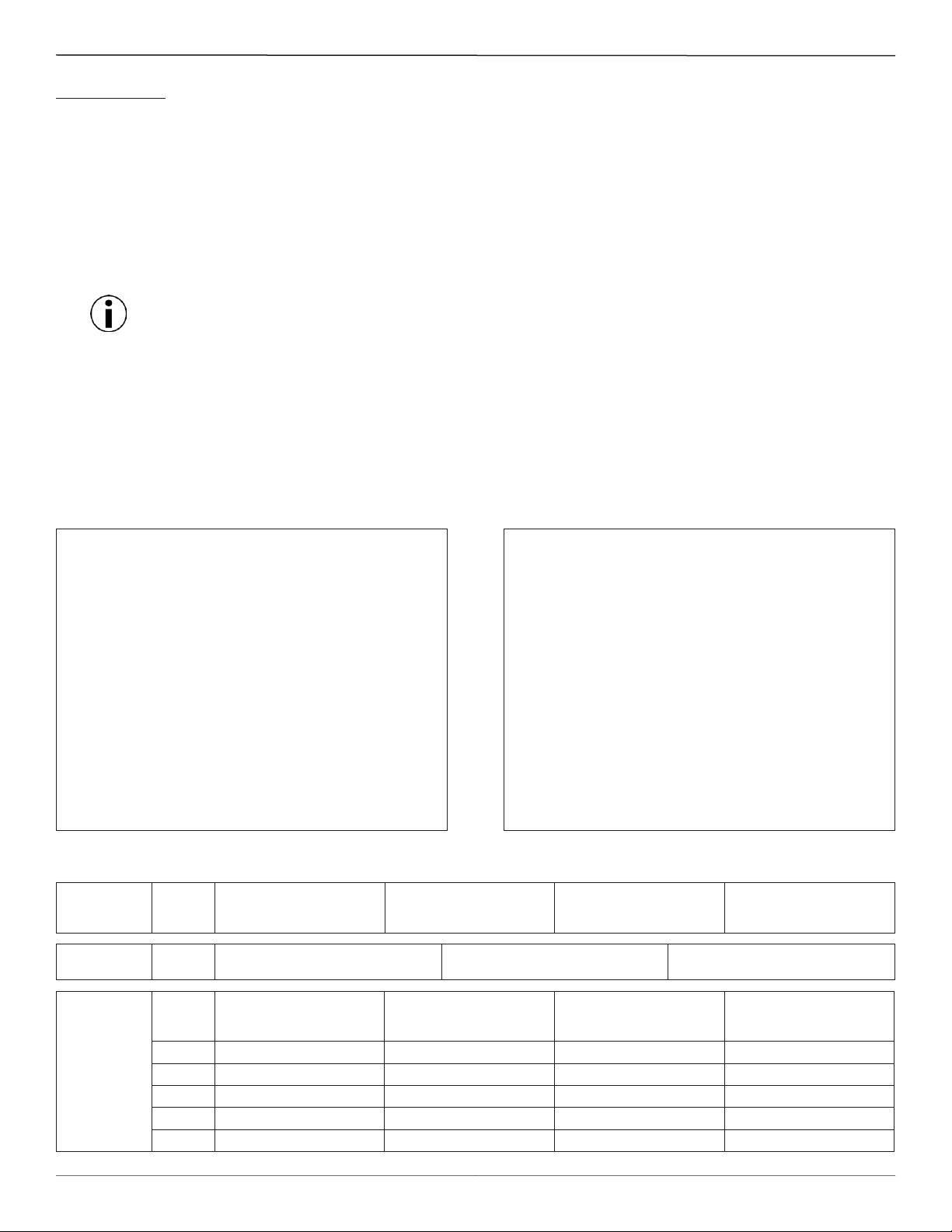
Table 1. Diagnostics and Factory Settings
C Calibration Information
Display only: A/D, Delta-R, Ref-R data values
D Diagnostics
Display only: List of unit parameters.
K Factory Calibration Settings
Display only: Cal. parameters; i.e., linearization and
temperature compensation coefcients.
R Factory Reset
Replaces user data with factory calibration data.
Table 2. Z Menu – Units and Scaling Setup
Select E=English M=Metric
Select 0= SFPS 5 = SMPS
or 1 = SCFM 6 = NCMH
or 2 = SCFH 7 = NCMM
or 3 = LBS/H 8 = KG/H
or 4 = GPM 9 = LPM
or 10 = SCMH
or 11 = NMPS
or 12 = SCMM
For Volumetric or Mass Flow
Select R = Round pipe or duct
or S = Square duct
Set Diameter or Wide X High (in inches or mm)
Set CMaxow = Maximum ow rate (span)
Set CMinow = Minimum ow rate (zero)
Note: Changing units requires rescaling the unit (set new zero and span).
Units
-
Table 3. V Menu – Output Conguration Setup
Select
4-20 mA Output
Conguration
NAMUR Mode
(Pulse) Output
Conguration
This page is subject to proprietary rights statement on last page
Select
Select
Source/Sink
Select
Select
Select
Set
Set
Set
Set
Set
4-20 mA Output #1 = Flow
4-20 mA Output #2 = Temp
1
NAMUR: OFF
1
Source = Pulse
Sink = Pulse
PFactor PFactor PFactor Switchpoint0
Sample Period Sample Period Sample Period Source state
Source state Source state Switchpoint0 Switchpoint1
Sink state Switchpoint1 Source state Sink state
n/a Sink state Sink state n/a
4-20 mA Output #1 = Flow
4-20 mA Output #2 = Flow
1
2
2
Source = Pulse
Sink = Alarm1
8
NAMUR: Low
4-20 mA Output #1 = Temp
4-20 mA Output #2 = Flow
2
3
3
Source = Alarm0
Sink = Pulse
4-20 mA Output #1 = Temp
4-20 mA Output #2 = Temp
NAMUR: High
4
3
4
Source = Alarm0
Sink = Alarm1
06EN003368 Rev. H
Page 9

ST75/ST75V Mass Flow Meter Fluid Components International LLC
“V” Menu Output Conguration Setup
Use the V menu to set up the 4-20 mA analog outputs (including NAMUR conguration) and source/sink (pulse) outputs.
Note: The display comes up to the last setting saved and stays for 2 seconds. If N or [ENTER] is entered, the menu proceeds to
the next item in the sequence (refer to “Table 3. V Menu – Output Conguration Setup” on page 8). If Y is entered, the display moves to the selection options and/or asks for conrmation. If you miss the option, select [Enter] repeatedly to loop around.
Analog Out
Output Mode Selected
4-20 mA #1: Flow
4-20 mA #2: Temp
Change? (Y/N)>
4-20 mA #1: Flow
4-20 mA #2: Temp
Enter 1 to make
the selection__
4-20 mA #1: Flow
4-20 mA #2: Flow
Enter 2 to make
the selection__
4-20 mA #1: Temp
4-20 mA #2: Flow
Enter 3 to make
the selection__
4-20 mA #1: Temp
4-20 mA #2: Temp
Enter 4 to make
the selection__
NAMUR Mode Selected
NAMUR: Off
Change? (Y/N)>
NAMUR: Off
Enter 1 to make
the selection #__
NAMUR: Low
Enter 2 to make
the selection #__
NAMUR: High
Enter 3 to make
the selection #__
Pulse Out
Pulse Out Selected
Source: Pulse
Sink: Pulse
Change? (Y/N)>
Source: Pulse
Sink: Pulse
Enter 1 to make
the selection #__
Source: Pulse
Sink: Alarm1
Enter 2 to make
the selection #__
Source: Alarm0
Sink: Pulse
Enter 3 to make
the selection #__
Source: Alarm0
Sink: Alarm1
Enter 4 to make
the selection #__
PFactor: 1.000
Change? (Y/N)>
if yes
Enter new factor: ____
Sample Period: 1 second
Change? (Y/N)>
if yes
Enter new Sample Period: ____
If alarm is a selected output
Set point1: 000 Set points are in the
same units as the fl ow
or temp.
Change? (Y/N)>
if yes
Enter new set point: ____
Resume normal operation
Source state:
High to Low
Change to Low to High?>
Example: COMMAND V (Reference Table 3)
Case: 4-20 mA #1 = Flow, 4-20 mA #2 = Temperature, NAMUR = Low, Source Out = Pulse, Sink = Alarm1
Pressing [V] [ENTER]
will display
“Output Mode Selected”
The last saved mode of the next menu item displays:
“4-20 mA #1 = Flow” “ 4-20 mA #2 = Temp” ...followed by the prompt:
“Change? (Y/N)”
Press [ENTER] (no change).
The last saved mode of the next menu item displays:
“NAMUR: Off” ...followed by the prompt:
“Change? (Y/N)” Select Y [Enter]. The display reads,
“NAMUR: Off” ...followed by the prompt:
“Enter 1 to make the selection #.” Select [ENTER]. Bypassing “1” the next display reads,
“NAMUR: Low” ...followed by the prompt:
“Enter 2 to make the selection #.” Select 2 and [ENTER]. “2” sets the new NAMUR conguration.
The last saved mode of the next menu item displays:
“Source: Pulse” “Sink: Pulse” ...followed by the prompt:
“Change? (Y/N)” Select Y [Enter]. The display reads,
“Source: Pulse” “Sink: Pulse” ...followed by the prompt:
“Enter 1 to make the selection #.” Select [ENTER]. Bypassing “1” the next display reads,
“Source: Pulse” “Sink: Alarm1” ...followed by the prompt:
“Enter 2 to make the selection #.” Select 2 and [ENTER]. “2” sets the new source/sink conguration.
The last saved mode of the next menu item displays:
“PFactor: 1.000” ...followed by the prompt:
“Change? (Y/N)>” Respond with “Y” to enter a factor anywhere from 0.001
to 1000. A pulse factor of 1.000 outputs 1 pulse per unit of
ow. If no change, select N and/or [ENTER] to continue.
This page is subject to proprietary rights statement on last page
9
06EN003368 Rev. H
Page 10

Fluid Components International LLC ST75/ST75V Mass Flow Meter
The last saved mode of the next menu item displays:
“Sample Period” ...followed by the prompt:
“Change? (Y/N)>” Respond with “Y” to enter a sample period value from
0.5 to 5 seconds.
If no change, select N and/or [ENTER] to continue.
The last saved mode of the next menu item displays:
“Source state:” “High to Low” ...followed by the prompt:
Change to “Low to High?>” Respond with “Y” to toggle to the alternate setting.
If no change, select N and/or [ENTER] to continue.
The last saved mode of the next menu item displays:
“Switchpt1” “0.0000000” ...followed by the prompt:
“Change? (Y/N)>” Respond with “Y” to enter a setpoint value (value is in
same units as the ow and must be within the calibrated
range).
If no change, select N and/or [ENTER] to continue.
The last saved mode of the next menu item displays:
“Sink state: ” “High to Low” ...followed by the prompt:
Change to “Low to High?>”. Respond with “Y” to toggle to the alternate setting.
If no change, select N and/or [ENTER] to continue to normal operation (programming nished).
Maintenance
The FCI instrument requires little maintenance. There are no moving parts or mechanical parts subject to wear in the instrument. The sensor
assembly, which is exposed to the process media, is composed of 316 SS and Hastelloy C.
Without detailed knowledge of the environmental parameters of the application surroundings and process media, FCI cannot make specic
recommendations for periodic inspection, cleaning, or testing procedures. However, some suggested general guidelines for maintenance steps
are offered below. Use operating experience to establish the frequency of each type of maintenance.
Calibration
Periodically verify the calibration of the output and recalibrate if necessary. FCI recommends every 18 months at a minimum.
Note: Thirty (30) second warm-up required before calibration check.
Electrical Connections
Periodically inspect cable connections on terminal strips and terminal blocks. Verify that terminal connections are tight and physically sound
with no sign of corrosion.
Remote Enclosure
Verify that the moisture barriers and seals protecting the electronics in the local enclosure is adequate and that no moisture is entering the
enclosure.
Electrical Wiring
FCI recommends occasional inspection of the system’s interconnecting cable, power wiring and ow element wiring on a “common sense”
basis related to the application environment. Periodically inspect the conductors for corrosion and check the cable insulation for signs of
deterioration.
Flow Element Connections
Verify that all seals are performing properly and that there is no leakage of the process media. Check for deterioration of the gaskets and
environmental seals used.
This page is subject to proprietary rights statement on last page
10
06EN003368 Rev. H
Page 11

ST75/ST75V Mass Flow Meter Fluid Components International LLC
Troubleshooting
Application Verication
After verifying that the ow meter is functioning, review the application parameters as shown below to verify the calibration matches the
process media.
Equipment Needed
Flow Instrument Calibration Data
Process Parameters and Limits
Check Serial Numbers
Verify that the serial number of the ow element and the ow transmitter electronics are the same. The ow element and the ow transmitter
are a matched set and cannot be operated independently of each other.
Check the Instrument Installation
Verify correct mechanical and electrical installation. Verify the ow element is mounted at least 20 diameters downstream and 10 diameters
upstream from any bends or interference in the process pipe or duct.
Check for Moisture
Check for moisture on the ow transmitter. Moisture may cause intermittent operation. Check for moisture on the ow element. If a compo
nent of the process media is near its saturation temperature it may condense on the ow element. Place the ow element where the process
media is well above the saturation temperature of any of the process gases.
Check Application Design Requirements
Application design problems may occur with rst time application instruments, although the design should also be checked on instruments
that have been in operation for some time. If the application design does not match eld conditions, errors occur.
1. Review the application design with plant operation personnel and plant engineers.
2. Ensure that plant equipment such as pressure and temperature instruments conform to the actual conditions.
3. Verify operating temperature, operating pressure, line size, and gas medium.
-
Verify Standard Versus Actual Process Conditions
The ow meter measures the mass ow rate. The mass ow rate is the mass of the gas owing through a pipe per time. Other ow meters,
such as an orice plate or a pitot tube, measure the volumetric ow rate. The volumetric ow rate is the volume of gas per time. If the readings displayed do not agree with another instrument, some calculations may be necessary before comparing them. To calculate the mass ow
rate, the volumetric ow rate, and the pressure and temperature, the point of measurement must be known. Use the following equation to
calculate the mass ow rate (Standard Volumetric Flow rate) for the other instrument:
Equation:
P
Q Q
= × ×
S A
Where:
QA= Volumetric Flow QS= Standard Volumetric Flow
PA= Actual Pressure TA= Actual Temperature
PS= Standard Pressure TS= Standard Temperature
PSIA and °R are used for pressure and temperature units.
Example:
QA= 1212.7 ACFM QS= 1485 SCFM
PA= 19.7 PSIA TA= 120 °F (580 °R)
PS= 14.7 PSIA TS= 70 °F (530 °R)
T
T
A
A
S
P
S
(Metric: Where bar(a) and °K are
used for pressure and temperature.)
(Metric: P
T
S =
= 1.01325 bar(a)
S
21.1°C (294.1K))
1212.7 ACFM
(
This page is subject to proprietary rights statement on last page
19.7 PSIA
1
)
580 °R
(
11
)
(
530 °R
14.7 PSIA
= 1485 SCFM
)
06EN003368 Rev. H
Page 12
Fluid Components International LLC ST75/ST75V Mass Flow Meter
Calibration Parameters Verication
The instrument uses a set of predetermined calibration parameters to process ow signals. Most of these parameters should not change. A data
package shipped with the instrument (typically on a CD-ROM) contains the ST75/ST75V Delta R Data Sheet. This contains the calibration
parameters stored in the ow transmitter at the factory. To verify that these parameters have not changed, complete the following:
1. Identify the appropriate Delta R data sheets by serial number of the instrument.
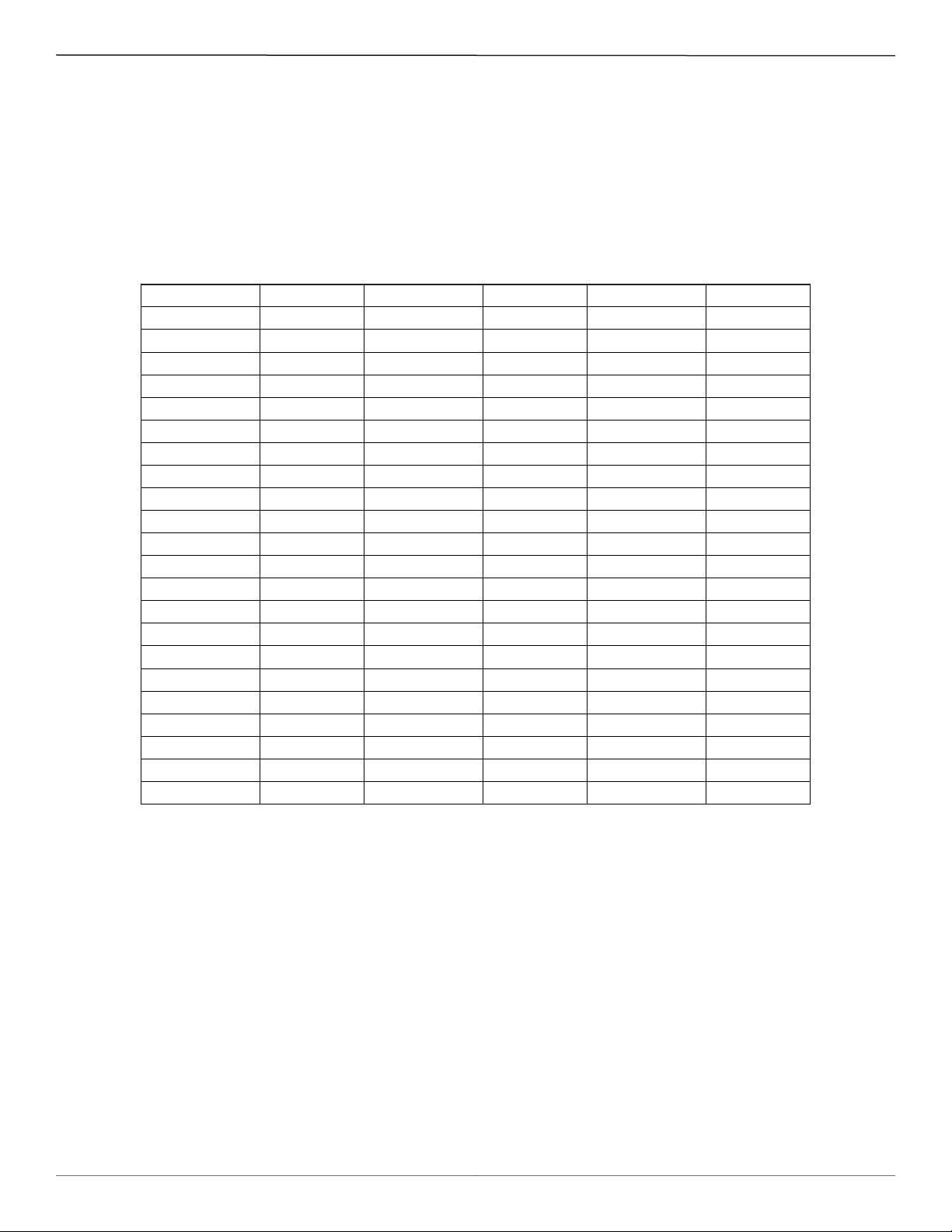
2. Press [D] [ENTER] to examine each of the parameters. The [ENTER] key allows scrolling one message at a time. Use Table 4
below to record actual instrument parameters. Compare with the Delta R data sheet’s ST75/ST75V parameters.
Table 4. Diagnostic Test Sequence on Display
S/W Version: dR Min: T SpanIDA C 0:
Flow Factor: dR Max: T ZeroIDA C 0:
Cmin Flow: Cal Ref: T SpanIDA C 1:
Cmax Flow: Tcslp: T ZeroIDA C 1:
Eng Units : Tcslp 0: State 0:
Line Size 0: Tcslp 2: Switch Pt 0:
Line Size 1: Tot Menu: State 1:
Cmin Temp : Tot Flag: Switch Pt 1:
Cmax Temp : Totalizer: K factor 1:
Min Flow: Rollover Cnt: K factor 2:
Max Flow: Fix Pt Flag: K factor 3:
Density: Pulse Factor: K factor 4:
*C1 [1]: Pulse Out: I factor:
*C1 [2]: Hours: Temp Flag:
*C1 [3]: Sample Period: Out Mode:
*C1 [4]: dR Slope : Namurmode:
*C1 [5]: dR Off Set : Boxcar Max:
Break Pt: Refr Slope: RTD-SLP-385:
*C2 [1]: Refr Off Set: % of Range:
*C2 [2]: SpanIDAC 0: User Name:
*C2 [3]: ZeroIDAC 0: Shop Order #:
*C2 [4]: SpanIDAC 1: Serial No.:
*C2 [5]: ZeroIDAC 1: Mode l#:
An issue may exist if parameters with an asterisk (*) have changed. Contact Customer Service if this is the case. If the parameters have not
changed, continue with the next section.
This page is subject to proprietary rights statement on last page
12
06EN003368 Rev. H
Page 13
ST75/ST75V Mass Flow Meter Fluid Components International LLC
Hardware Verication
Equipment Required:
• Digital Multimeter
• Screwdriver
The ST75/ST75V ow meter is made up of these basic components:
• Sensor element.
• Customer interface circuit board
• Control circuit assembly circuit board module.
• Electronics enclosure.
Step 1
Verify fuse (F1) located on the customer interface circuit board is in normal working condition.
Remove power from the instrument. Open the electronics enclosure exposing the customer interface circuit board. This circuit board is
located under the shorter enclosure lid along with all of the power and input/output connections. Unscrew the clear cover on the fuse and pull
the fuse out of the fuse holder. Check the fuse for continuity. If fuse reads open, replace with equivalent component (FCI part no. 019933-01),
ickmann Inc. Series 374, 1.6 A (amp code 1160), package 0410 (short radial leads).
W
AC power customer interface circuit boar
d
shown. Fuse (F1) on DC power customer inter
face circuit board located in similar position.
FC88/CLI
P3
ON
-
PULSE
OUT
ANALOG
TB3
SOURCE
COM
SINK
TB2
OUT
4-20mA
RTN
4-20mA
FCI
AC
LINE
85-265VAC
AC
NEUT
S/N
F1
(TR5, 250V
1.6A, SB, UL)
EARTH
GND
POWER IN
Fuse (F1)
TB1
C00935-1
Step 2
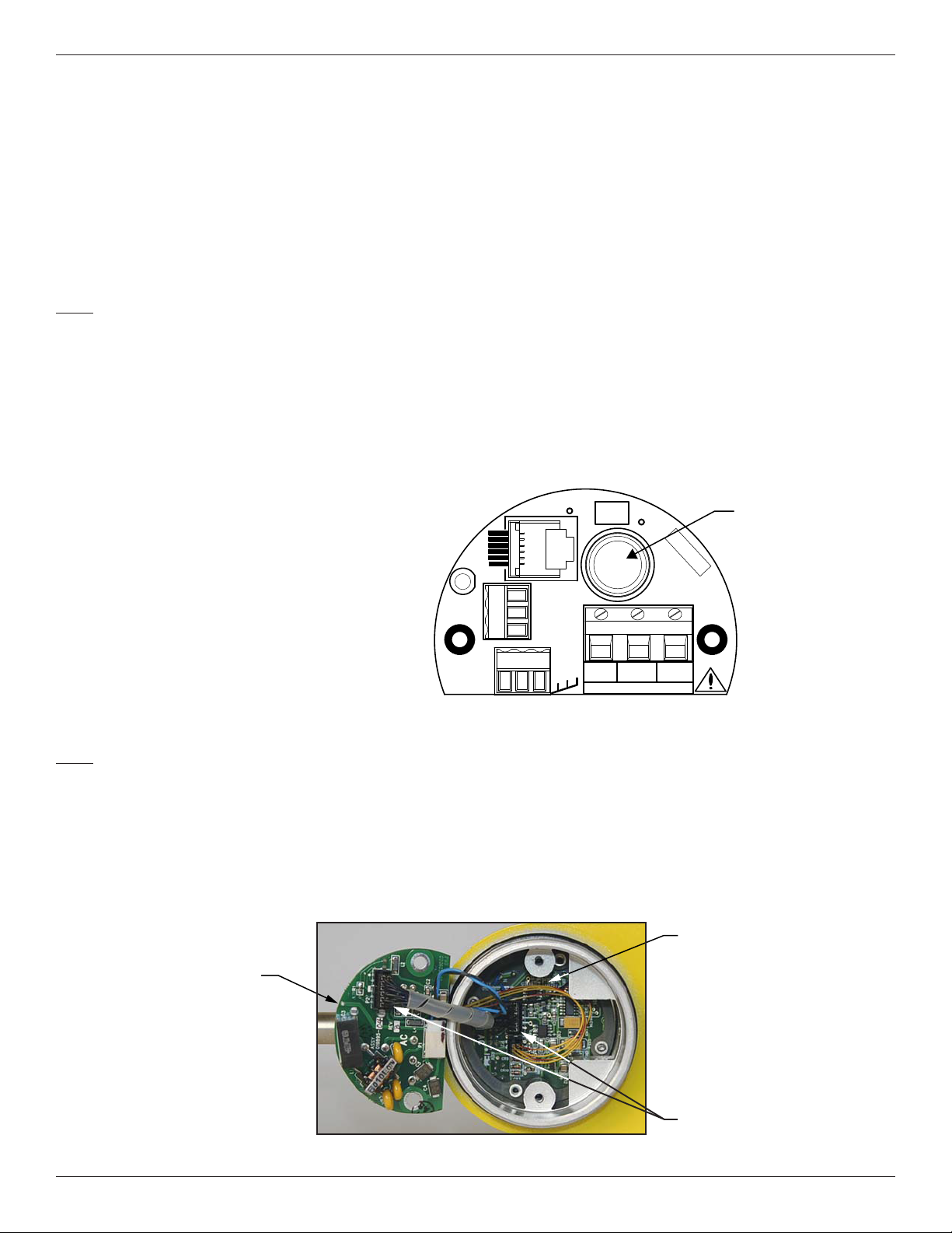
Verify interconnecting cable from the customer interface board and the control circuit board assembly module are correctly seated into the
appropriate header.
Remove power from the instrument. Open the electronics enclosure exposing the customer interface circuit board. This circuit board is
located under the shorter enclosure lid along with all of the power and input/output connections. Remove the 2 screws securing the interface
circuit board to the electronics enclosure. Carefully lift the interface board out of the housing exposing the interconnecting cable between the
interface board and the control circuit assembly. Verify cable is seated rmly at both ends of the cable header.
Control Circuit
Assembly
Interface Board
This page is subject to proprietary rights statement on last page
Cable Header
13
06EN003368 Rev. H
Page 14
Fluid Components International LLC ST75/ST75V Mass Flow Meter
Step 3
Verify sensor element continuity and resistance.
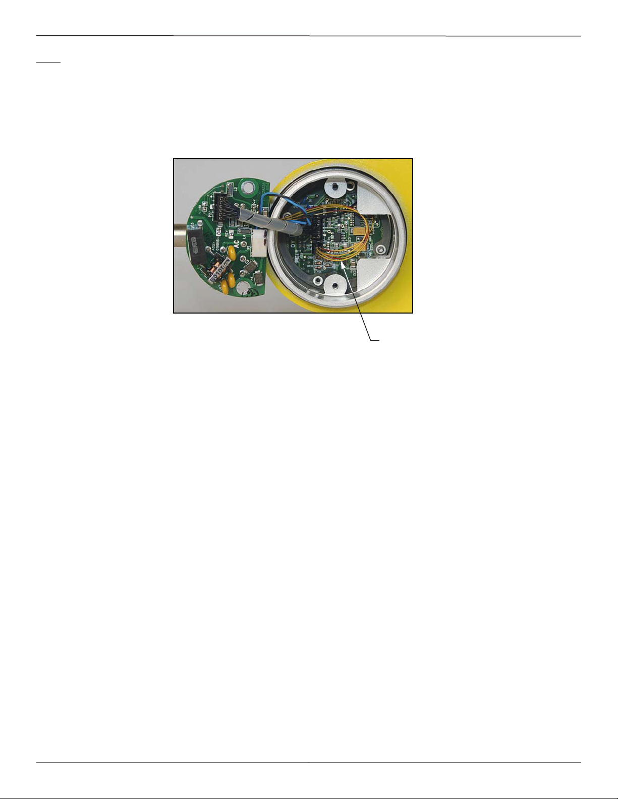
Remove sensor element cable from the bottom of the control circuit assembly. Note that two of the wires have a red stripe and are located
closest to the interconnecting cable header. Using an ohmmeter verify that resistance between the 2 red striped wires is approximately 1100
ohms ±20 ohms. This resistance is temperature dependent. The resistance at 70 degrees F is about 1082 ohms. V
erify the resistance between
the 2 natural colored wires are approximately the same.
Sensor Element
Cable
FCI provides full in-house technical support. Additional technical representation is also provided by FCI eld representatives. Before contacting a eld or in-house representative, please perform the troubleshooting techniques outlined in this document. If problems persist, contact
the FCI Customer Service department at 1-800-854-1993 or 1-760-744-6950.
Contact FCI to obtain a Return Authorization before returning the instrument. The form contains a declaration of decontamination cleaning
information that the instrument must comply with before it is shipped to FCI.
This page is subject to proprietary rights statement on last page
14
06EN003368 Rev. H
Page 15
ST75/ST75V Mass Flow Meter Fluid Components International LLC
Transmitter Circuit Calibration Check (Delta R Verication)
References
• Delta ‘R’ Data Sheet
Equipment
• FC88 Communicator or equivalent.
• DVM
• Delta R data sheet - Match by serial numbers
• 2 ea. precision decade resistance boxes, 0.1% (Largest steps: 1k ohm, smallest steps 0.01 ohms)
• Small at blade screwdriver, 3/32 inches wide blade
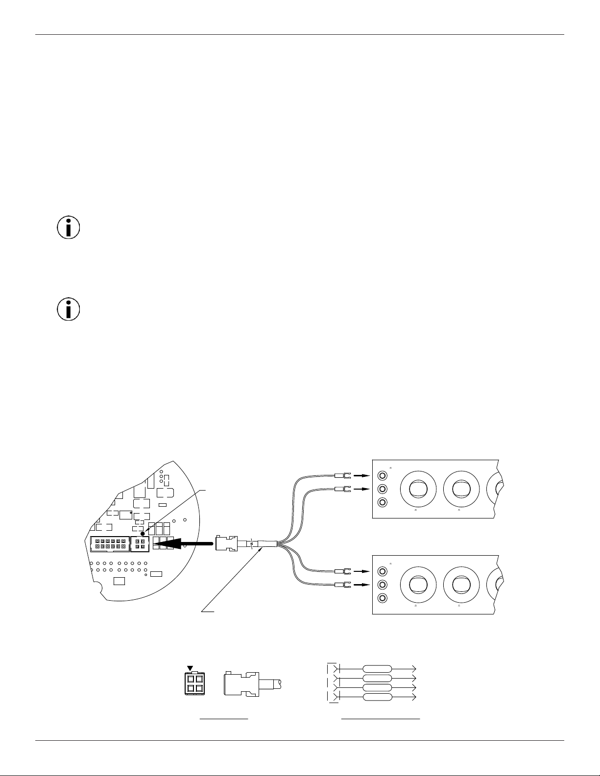
• FCI normalization cable, FCI part number 006407
Procedure
Note: Thirty (30) second warm-up required before calibration check.
1. Verify all “D” mode calibration parameters are correct according to the meter’s Delta R data sheet before starting verication.
2. Turn power OFF.
3. Mark all sensor element wires connected to the circuit board for easier reconnection to the proper terminals. Disconnect the wires.
4. Connect the resistance decade box to the electronics as per the appropriate wiring diagram for the ST75/ST75V.
Note: Interconnecting wiring (resistance decade box to electronics) must be same gauge and length to avoid any inaccuracies in
the Delta R verication caused by unequal wire lengths and/or wire gauges.
5. Set both decade boxes for the nominal resistance value (1000 ohms) ±0.01%
6. Connect DVM to the meter’s output termination and monitor the meter output.
7. Turn the power ON and allow the instrument 5 minutes to stabilize.
8. With the FC88 connected, Press [T] [Enter] to view the Normal Operating Mode.
9. Adjust the Active decade box (Reference decade box remains xed @ 1000 ohms) to achieve the appropriate Delta R for the dis
played ow value and output, noted on the meter’s Delta R data sheet.
10. Note the [C] mode and verify the meter’s displayed TCDR and REFR values corresponding to the displayed ow rate as per the
meter’s Delta R data sheet.
11. Return to normal mode operation ([T] mode).
ACTIVE
1433-W DECADE RESISTOR GENERAL RADIO USA
K
C11
GND
IN USA
MADE
V+
PIN ONE
INDICATOR
C10
C1
C5
U3
C2
C4
C7
ACT
FCI
P2
AC
REV-
P1
J1
U5
CR8
CR7
CR6
R5
REF
CR9
CR10
REV
-
PWB 019695-01
C12
CR3
ORANGE
ORANGE
BLACK
BLACK
NORMALIZATION CABLE
10
H
0
1
2
3
L
4
5
X
6
9
7
3
4
2
5
6
1K STEPS
23mA MAX
0
1
7
1K STEPS
23mA MAX
8
X
9
8
G
REFERENCE
1433-W DECADE RESISTOR GENERAL RADIO USA
K
10
H
L
G
2
3
4
5
3
4
5
1
6
100 STEPS
1
2
6
100 STEPS
7
80mA MAX
7
80mA MAX
0
9
8
0
9
8
1
2
3
4
5
X
6
1
2
3
4
5
X
6
FCI P/N 006407
-
PIN ONE
1
2
END VIEW SIDE VIEW
This page is subject to proprietary rights statement on last page
4
3
CABLE PIN OUTS
15
1
2
3
4
BLACK
BLACK
ORANGE ACT 4
CABLE WIRING SCHEMATIC
REF 1
REF 2
ACT 3ORANGE
C00933-1-2
06EN003368 Rev. H
Page 16

Fluid Components International LLC ST75/ST75V Mass Flow Meter
INTENTIONALLY LEFT BLANK
This page is subject to proprietary rights statement on last page
16
06EN003368 Rev. H
Page 17
ST75/ST75V Mass Flow Meter Fluid Components International LLC
Appendix A - Approval Information
EU Information
This page is subject to proprietary rights statement on last page
17
06EN003368 Rev. H
Page 18

Fluid Components International LLC ST75/ST75V Mass Flow Meter
Specic Conditions of Use per FM16ATEX0008X
1. The ambient temperature range and applicable temperature class of the sensor probe is based on the maximum process temperature for the particular application as follows; T6…T1 for T
of -40 °C to +65 and T
ambient
of -40 °C to +260 °C. Probe
process
assembly design temperatures are part number dependent. Low temperature models have design temperatures from -40°C to
+121°C. Medium temperature models have design temperatures from -40 °C to +260 °C.
2. Process Temperature: Maximum process temperature range is -40 °C to +260 °C. Process temperature varies for ow element
installed. The relationship between the temperature class, the maximum surface temperature and the process temperature is as
follows:
Sensing Element:
T6 / T85°C for a process temperature range of -40 °C to +39 °C.
T5 / T100°C for a process temperature range of -40 °C to +54 °C.
T4 / T135°C for a process temperature range of -40 °C to +89 °C.
T3 / T200°C for a process temperature range of -40 °C to +154 °C.
T2 / T300°C for a process temperature range of -40 °C to +177 °C.
T1 for a process temperature range of -40 °C to +260 °C.
3. Consult the manufacturer if dimensional information on the ameproof joints is necessary.
4. The painted surfaces of the mass ow meter may store electrostatic charge and become a source of ignition in applications
with a low relative humidity <~30% relative humidity where the painted surface is relatively free of surface contamination
such as dirt, dust, or oil. Guidance on protection against the risk of ignition due to electrostatic discharge can be found in IEC
TR60079-32 (in preparation). Cleaning of the painted/unpainted surface should only be done with a damp cloth.
5. The probe when remotely located from the enclosure has ying lead conductors that requires the remote probe to be connected to a suitably certied Ex d or Ex e terminal box for connecting to the external supply circuit.
6. Customer to supply wire rated 10 °C minimum above maximum ambient temperature of installation location to a suitably
certied Ex d or Ex e terminal box.
This page is subject to proprietary rights statement on last page
18
06EN003368 Rev. H
Page 19
ST75/ST75V Mass Flow Meter Fluid Components International LLC
Safety Instructions for the use of the ST51/75 ow meter in Hazardous Areas
Approval FM16ATEX0008X/IECEX FMG 16.0009X for:
II 2 G Ex db IIC T6...T1 Gb
II 2 D Ex tb IIIC T85°C...T300°C Db; IP66/IP67
The ST51/75 series consist of a sensing element and associated integral or remote mounted electronics mounted in a type “d” ameproof enclosure.
Relation between ambient temperature, process temperature, and temperature class is as follows:
Ambient temperature range (Ta): T6/T85°C for : -40ºC <Ta< + 65ºC
Process temperature range (Tp): T6 / T85°C: -40°C < Tp < +39°C
T5 / T100°C: -40°C <Tp < +54°C
T4 / T135°C: -40°C < Tp < +89°C
T3 / T200°C: -40°C < Tp < +154°C
T2 / T300°C: -40°C < Tp < +177°C
T1: -40°C < Tp < +260°C
Electrical data: Power supply: 85 to 265 VAC, 50/60 Hz, 10 W; 18–36 VDC, 9.6 W.
Dansk Sikkerhedsforskrifter Italiano Normative di sicurezza
Deutsch Sicherheitshinweise Nederlands Veiligheidsinstructies
English Safety instructions Português Normas de segurança
Ελληνική Υποδείξεις ασφαλείας Español Instrucciones de seguridad
Suomi Turvallisuusohjeet Svenska Säkerhetsanvisningar
Français Consignes de sécurité
DK Dansk – Sikkerhedsforskrifter
Disse sikkerhedsforskrifter gælder for Fluid Components, ST51/75 EF-typeafprøvningsattest-nr. FM16ATEX0008X/IECEX FMG 16.0009X attestens nummer på typeskiltet) er egnet til at
blive benyttet i eksplosiv atmosfære kategori II 2 GD.
1) Ex-anlæg skal principielt opstilles af specialiseret personale.
2) ST51/75 skal jordforbindes.
3) Klemmerne og elektronikken er monteret i et hus, som er beskyttet af en eksplosionssikker kapsling med følgende noter:
• Gevindspalten mellem huset og låget er på en sådan måde, at ild ikke kan brede sig inden i det.
• Ex-„d“ tilslutningshuset er forsynet med et ½“ NPT og/eller M20x1.5 gevind for montering af en Ex-„d“ kabelindføring, der er attesteret iht IEC/EN 60079-1.
• Det er vigtigt at sørge for, at forsyningsledningen er uden spænding eller eksplosiv atmosfære ikke er til stede, før låget åbnes og når låget er åbent på „d” huset (f.eks. ved tilslutning
eller servicearbejde).
• Låget på „d” huset skal være skruet helt ind, når apparatet er i brug. Det skal sikres ved at dreje en af låseskruerne på låget ud.
D A Deutsch – Sicherheitshinweise
Diese Sicherheitshinweise gelten für die Fluid Components, ST51/75 ow meter gemäß der EG-Baumusterprüfbescheinigung Nr. FM16ATEX0008X/IECEX FMG 16.0009X
(Bescheinigungsnummer auf dem Typschild) der Kategorie II 2 GD.
1) Die Errichtung von Ex-Anlagen muss grundsätzlich durch Fachpersonal vorgenommen werden.
2) Der ST51/75 muß geerdet werden.
3) Die Klemmen und Elektroniken sind in einem Gehäuse in der Zündschutzart druckfeste Kapselung („d“ ) eingebaut.
• Der Gewindespalt zwischen dem Gehäuse und dem Deckel ist ein zünddurchschlagsicherer Spalt.
• Das Ex-“d“ Anschlussgehäuse besitzt ein 1/2“ NPT und/oder M20x1.5 Gewinde für den Einbau einer nach IEC/EN 60079-1 bescheinigten Ex-“d“ Kabeleinführung.
• Es ist sicherzustellen, dass vor dem Öffnen und bei geöffnetem Deckel des „d“ Gehäuses (z.B. bei Anschluss oder Service- Arbeiten) entweder die Versorgungsleitung spannungsfrei
oder keine explosionsfähige Atmosphäre vorhanden ist.
• Der Deckel des „d“ Gehäuses muss im Betrieb bis zum Anschlag hineingedreht sein. Er ist durch eine der Deckelarretierungsschrauben zu sichern.
This page is subject to proprietary rights statement on last page
19
06EN003368 Rev. H
Page 20

Fluid Components International LLC ST75/ST75V Mass Flow Meter
GB IRL English – Safety instructions
These safety instructions are valid for the Fluid Components, ST51/75 ow meter to the EC type approval certicate no FM16ATEX0008X/IECEX FMG 16.0009X (certicate number on
the type label) for use in potentially explosive atmospheres in Category II 2 GD.
1) The installation of Ex-instruments must be made by trained personnel.
2) The ST51/75 must be grounded.
3) The terminals and electronics are installed in a ame proof and pressure-tight housing with following notes:
• The gap between the housing and cover is an ignition-proof gap.
• The Ex-“d“ housing connection has a ½“ NPT and/or M20x1.5 cable entry for mounting an Ex-d cable entry certied according to IEC/EN 60079-1.
• Make sure that before opening the cover of the Ex”d“ housing, the power supply is disconnected or there is no explosive atmosphere present (e.g. during connection or service work).
• During normal operation: The cover of the “d“ housing must be screwed in completely and locked by tightening one of the cover locking screws.
GR Ελληνική – Υποδείξεις ασφαλείας
Αυτές οι οδηγίες ασφαλείας ισχύουν για τα Ροόµετρα της Fluid Components τύπου ST51/75 που φέρουν Πιστοποιητικό Εγκρίσεως Ευρωπαϊκής Ένωσης, µε αριθµό πιστοποίησης
FM16ATEX0008X/IECEX FMG 16.0009X (οαριθµός πιστοποίησης βρίσκεται πάνω στην ετικέτα τύπου του οργάνου) για χρήση σε εκρηκτικές ατµόσφαιρες της κατηγορίας II 2 GD.
1) Η εγκατάσταση των οργάνων µε αντιεκρηκτική προστασία πρέπει να γίνει από εξειδικευµένο προσωπικό.
2) Το όργανο τύπου ST51/75 πρέπει να είναι γειωµένο.
3) Τα τερµατικά ηλεκτρικών συνδέσεων (κλέµες) και τα ηλεκτρονικά κυκλώµατα είναι εγκατεστηµένα σε περίβληµα αντιεκρηκτικό και αεροστεγές σύµφωνα µε τις ακόλουθες παρατηρήσεις:
• Το κενό ανάµεσα στο περίβληµα και στο κάλυµµα είναι τέτοιο που αποτρέπει την διάδοση σπινθήρα.
• Το “Ex-d” αντιεκρηκτικό περίβληµα, έχειανοίγµατα εισόδου καλωδίου µε διάµετρο ½” NPT ή/και M20x1.5, κατάλληλα για τοποθέτηση υποδοχής αντιεκρηκτικού καλωδίου πιστοποιηµένης κατά IEC/EN 60079-1.
• Βεβαιωθείτε ότι πριν το άνοιγµα καλύµµατος του του “Ex-d” αντιεκρηκτικού περιβλήµατος, η τάση τροφοδοσίας είναι αποσυνδεδεµένη ή ότι δεν υφίσταται στη περιοχή εκρηκτική
ατµόσφαιρα (π χ κατά τη διάρκεια της σύνδεσης ή εργασιών συντήρησης).
• Κατά τη διάρκεια οµαλής λειτουργίας: Το κάλυµα του “d” καλύµµατος αντιεκρηκτικού περιβλήµατος πρέπει να είναι εντελώς βιδωµένο και ασφαλισµένο, σφίγγοντας µία από τις
βίδες ασφαλείας του περιβλήµατος.
FIN Suomi – Turvallisuusohjeet
Nämä turvallisuusohjeet koskevat Fluid Components, ST51/75 EY-tyyppitarkastustodistuksen nro. FM16ATEX0008X/IECEX FMG 16.0009X (todistuksen numero näkyy tyyppikilvestä)
käytettäessä räjähdysvaarallisissa tiloissa luokassa II 2GD.
1) Ex-laitteet on aina asennettava ammattihenkilökunnan toimesta.
2) ST51/75 on maadoitettava.
3) Syöttöjännitteen kytkemisessä tarvittavat liittimet ja elektroniikka on asennettu koteloon jonka rakenne kestää räjähdyspaineen seuraavin lisäyksin :
• Kotelon ja kannen välissä on räjähdyksen purkausväli.
• Ex-d liitäntäkotelossa on ½“ NPT ja/tai M20x1.5 kierre IEC/EN 60079-1 mukaisen Ex-d kaapeliläpiviennin asennusta varten.
• Kun “d“-kotelon kansi avataan (esim. liitännän tai huollon yhteydessä), on varmistettava, että joko syöttöjohto on jännitteetön tai ympäristössä ei ole räjähtäviä aineita.
• “d“ -kotelon kansi on kierrettävä aivan kiinni käytön yhteydessä ja on varmistettava kiertämällä yksi kannen lukitusruuveista kiinni.
F B L Français – Consignes de sécurité
Ces consignes de sécurité sont valables pour le modèle ST51/75 de la société Fluid Components (FCI) conforme au certicat d’épreuves de type FM16ATEX0008X/IECEX FMG
16.0009X (numéro du certicat sur l’étiquette signalétique) conçu pour les applications dans lesquelles un matériel de la catégorie II2GD est nécessaire.
1) Seul un personnel spécialisé et qualié est autorisé à installer le matériel Ex.
2) Les ST51/75 doivent être reliés à la terre.
3) Les bornes pour le branchement de la tension d’alimentation et l’électronique sont logées dans un boîtier à enveloppe antidéagrante avec les notes suivantes :
• Le volume entre le boîtier et le couvercle est protégé en cas d’amorçage.
• Le boîtier de raccordement Ex-d dispose d’un letage ½“ NPT et/ou M20x1.5 pour le montage d’un presse-étoupe Ex-d certié selon la IEC/EN 60079-1.
• Avant d’ouvrir le couvercle du boîtier « d » et pendant toute la durée où il le restera (pour des travaux de raccordement, d’entretien ou de dépannage par exemple), il faut veiller à ce
que la ligne d’alimentation soit hors tension ou à ce qu’il n’y ait pas d’atmosphère explosive.
• Pendant le fonctionnement de l’appareil, le couvercle du boîtier « d » doit être vissé et serré jusqu’en butée. La bonne xation du couvercle doit être assurée en serrant une des vis
d’arrêt du couvercle.
This page is subject to proprietary rights statement on last page
20
06EN003368 Rev. H
Page 21

ST75/ST75V Mass Flow Meter Fluid Components International LLC
I Italiano – Normative di sicurezza
Queste normative di sicurezza si riferiscono ai Fluid Components, ST51/75 secondo il certicato CE di prova di omologazione n° FM16ATEX0008X/IECEX FMG 16.0009X (numero del
certicato sulla targhetta d’identicazione) sono idonei all’impiego in atmosfere esplosive applicazioni che richiedono apparecchiature elettriche della Categoria II 2 GD.
1) L’installazione di sistemi Ex deve essere eseguita esclusivamente da personale specializzato.
2) I ST51/75 devono essere collegati a terra.
3) I morsetti per il collegamento e l’elettronica sono incorporati in una custodia a prova di esplosione („d“) con le seguenti note:
• La sicurezza si ottiene grazie ai cosidetti „interstizi sperimentali massimi“, attraverso i quali una eventuale accensione all’interno della custodia non può propagarsi all’esterno
oraggiungere altre parti dell’impianto.
• La scatola di collegamento Ex-d ha una lettatura ½“ NPT e/o M20x1.5 per il montaggio di un passacavo omologato Ex-d secondo IEC/EN 60079-1.
• Prima di aprire il coperchio della custodia „d“ (per es. durante operazioni di collegamento o di manutenzione) accertarsi che l’apparecchio sia disinserito o che non si trovi in presenza di
atmosfere esplosive.
• Avvitare il coperchio della custodia „d“ no all’arresto. Per impedire lo svitamento del coperchio é possibile allentare una delle 2 viti esagonali poste sul corpo della custodia,
incastrandola nella sagoma del coperchio.
NL B Nederlands – Veiligheidsinstructies
Deze veiligheidsinstructies gelden voor de Fluid Components, ST51/75 overeenkomstig de EG-typeverklaring nr. FM16ATEX0008X/IECEX FMG 16.0009X (nummer van de verklaring op
het typeplaatje) voor gebruik in een explosieve atmosfeer volgens Categorie II 2GD.
1) Installatie van Ex-instrumenten dient altijd te geschieden door geschoold personeel.
2) De ST51/75 moet geaard worden.
3) De aansluitklemmen en de electronika zijn ingebouwd in een drukvaste behuizing met de volgende opmerkingen:
• De schroefdraadspleet tussen de behuizing en de deksel is een ontstekingsdoorslagveilige spleet.
• De Ex-d aansluitbehuizing heeft een ½” NPT of een M20x1.5 schroefdraad voor aansluiting van een volgens IEC/EN 60079-1 goedgekeurde Ex- ‘d’ kabelinvoer.
• Er moet worden veilig gesteld dat vóór het openen bij een geopende deksel van de ‘d’ behuizing (bijv. bij aansluit- of servicewerkzaamheden) hetzij de voedingsleiding spanningsvrij is,
hetzij geen explosieve atmosfeer aanwezig is.
• De deksel van de ‘d’ behuizing moet tijdens bedrijf tot aan de aanslag erin geschroefd zijn. Hij moet door het eruit draaien van een van de dekselborgschroeven worden geborgd.
P Português – Normas de segurança
Estas normas de segurança são válidas para os Fluid Components, ST51/75 conforme o certicado de teste de modelo N.º FM16ATEX0008X/IECEX FMG 16.0009X (número do
certicado na plaqueta com os dados do equipamento) são apropriados para utilização em atmosferas explosivas categoria II 2 GD.
1) A instalação de equipamentos em zonas sujeitas a explosão deve, por princípio, ser executada por técnicos qualicados.
2) Os ST51/75 Flexmasster precisam ser ligados à terra.
3) Os terminais e a electrónica para a conexão da tensão de alimentação estão instalados num envólucro com protecção contra ignição á prova de sobrepressão com as seguintes notas:
• A fenda entre o envólucro e a tampa deve ser á prova de passagem de centelha.
• O envólucro de conexão Ex-“d“ possui uma rosca ½“ NPT e/ou M20x1.5 para a entrada de cabos Ex-“d“ certicado conforme a norma IEC/EN 60079-1.
• Deve-se assegurar que, antes de abrir a tampa do armário „d“ ( por exemplo, ao efectuar a conexão ou durante trabalhos de manutenção), o cabo de alimentação esteja sem tensão
ou que a atmosfera não seja explosíva.
• Durante a operação, a tampa do envólucro „d“ deve estar aparafusada até o encosto. A tampa deve ser bloqueada, por um dos parafusos de xação.
E Español – Instrucciones de seguridad
Estas indicaciones de seguridad son de aplicación para el modelo ST51/75 de Fluid Components, según la certicación CE de modelo Nº FM16ATEX0008X/IECEX FMG 16.0009X para
aplicaciones en atmósferas potencialmente explosivas según la categoría II 2 GD (el número decerticación se indica sobre la placa informativa del equipo).
1) La instalación de equipos Ex tiene que ser realizada por personal especializado.
2) Los ST51/75 tienen que ser conectados a tierra.
3) Los bornes de conexión y la unidad electrónica están montados dentro de una caja con protección antideagrante y resistente a presión, considerándose los siguientes puntos:
• La holgura entre la rosca de la tapa y la propia de la caja está diseñada a prueba contra ignición.
• La caja tiene conexiones eléctricas para entrada de cables con rosca ½” NPT y/o M20x1.5, donde deberán conectarse prensaestopas certicados Exd según IEC/EN60079-1.
• Antes de la apertura de la tapa de la caja «Exd“ (p. ej. durante los trabajos de conexionado o de puesta en marcha) hay que asegurar que el equipo se halle sin tensión o que no exista
presencia de atmósfera explosiva.
• Durante el funcionamiento normal: la tapa de la caja antideagrante tiene que estar cerrada, roscada hasta el tope, debiendose asegurar apretando los tornillos de bloqueo.
This page is subject to proprietary rights statement on last page
21
06EN003368 Rev. H
Page 22

Fluid Components International LLC ST75/ST75V Mass Flow Meter
S Svenska – Säkerhetsanvisningar
Säkerhetsanvisningarna gäller för Fluid Components, Flödesmätare typ ST51/75 enligt EG-typkontrollintyg nr FM16ATEX0008X/IECEX FMG 16.0009X (intygsnumret åternns på
typskylten) är lämpad för användning i explosiv gasblandning i kategori II 2 GD.
1) Installation av Ex- klassade instrument måste alltid utföras av fackpersonal.
2) ST51/75 måste jordas.
3) Anslutningsklämmorna och elektroniken är inbyggda i en explosions och trycktät kapsling med följande kommentar:
• Spalten mellan kapslingen och lockets gänga är amsäker.
• Ex-d kapslingen har en ½“ NPT och / eller M20x1.5 gänga för montering av en IEC/EN 60079-1 typkontrollerad Ex- „d“ kabel förskruvning.
• När Ex- „d“-kapslingens lock är öppet (t.ex. vid inkoppling - eller servicearbeten) ska man se till att enheten är spänningslös eller att ingen explosiv gasblandning förekommer.
• Under drift måste Ex - d“-kapslingens lock vara iskruvad till anslaget. För att säkra locket skruvar man i en av lockets insex låsskruvar.
This page is subject to proprietary rights statement on last page
22
06EN003368 Rev. H
Page 23
ST75/ST75V Mass Flow Meter Fluid Components International LLC
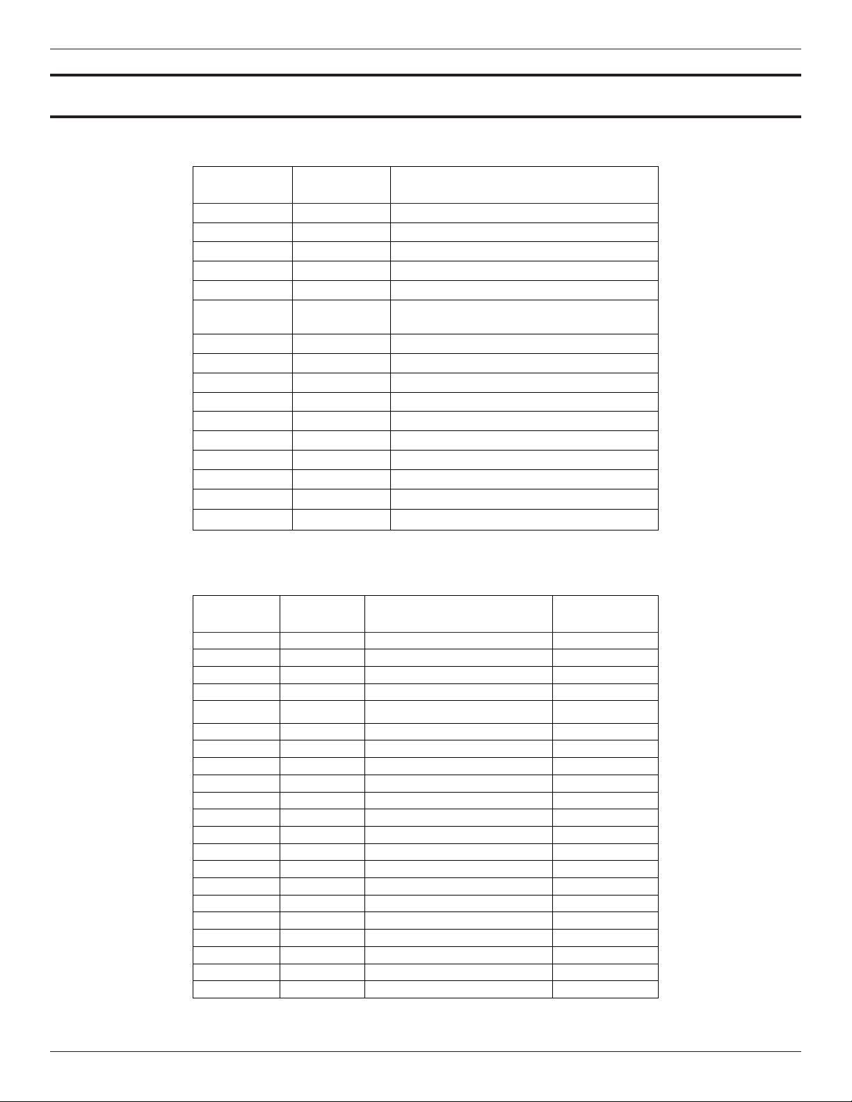
Appendix B - List Commands
Table 5. ST75/ST75V List of Single Letter Commands
COMMAND
MNEMONIC
A R AvgDelta_r, AvgRef
B R Delta_r, Ref_r
C R Tcdelta_r, Ref_r
D R Diagnostics
F R/W Kfactors
G R/W Clear FlashEE, Boxcar Count, ADC to Ohms
K R/W Cal Parameters
L R/W Output Cal
N W Warm Restart
R W Factory Restore
S R/W Totalizer Menu On/Off
T R Normal Mode
V R/W Output Cong
W R/W Totalizer
Y W Command Line Interface
Z W Flow units, Pipe Size, and LCD Scaling
COMMAND
FUNCTION
COMMAND DESCRIPTION
Cal
Table 6. ST75/ST75V List of CLI Commands
COMMAND
MNEMONIC
BK R/W Break Point Float
BM R/W Boxcar Filter Max Integer
CM R/W Cminow Float
CR R/W Calibration Ref Float
CX R/W Cmaxow Float
C1[1-5] R/W Coefcients set1 Float
C2[1-5] R/W Coefcients set2 Float
DI R Diagnostics Null
DM R/W DeltaR Minimum Float
DN R/W Density Float
DR R Delta R Float
DX R/W DeltaR Maximum Float
DS R/W DeltaR Slope Float
DF R/W DeltaR Offset Float
EU R/W Engineering Units Integer
FF R/W Flow Factor Float
FP R/W Fix Point Flag Integer
F0 R/W Pulse Out State0 Integer
F1 R/W Pulse Out State1 Integer
HR R/W Tot Dump Hours Cntr Integer
IF R/W I Factor Float
COMMAND
FUNCTION
COMMAND DESCRIPTION DATA TYPE
This page is subject to proprietary rights statement on last page
23
06EN003368 Rev. H
Page 24

Fluid Components International LLC ST75/ST75V Mass Flow Meter
Table 6. ST75/ST75V List of CLI Commands, Cont.
COMMAND
MNEMONIC
COMMAND
FUNCTION
COMMAND DESCRIPTION DATA TYPE
K[1-4] R/W K Factors Float
L0 R/W Line Size 0 Float
L1 R/W Line Size 1 Float
MN R/W Minow Float
MX R/W Maxow Float
NN R/W Namur Mode Integer
OM R/W Outmode Integer
PF R/W Pulse Factor Float
PL R/W Pulse Out Integer
PS R/W Pulse Sample Period Float
PW R/W Pulse Width Float
P0 R/W Switch Point0 Integer
P1 R/W Switch Point1 Integer
RO R/W RollOver Cntr Long
RR R Reference R Float
RS R/W RefR Slope Float
RF R/W RefR Offset Float
SF R SFPS Flow Float
SN R/W Serial Number
SO R/W Shop Order Number
String (1 6 chars max.)
S0 R/W SpanDAC0 for 4-20mA #1 Integer
S3 R/W SpanDAC1 for 4-20mA #2 Integer
S2 W Save FACTORY N/A
TC R TCDeltaR Float
TD R/W Tcslp Float
TF R/W Totalizer OFF/ON Flag Integer
TM R/W Cmintemp Float
TP R/W Totalizer Temperature Flag Integer
TT R/W Totalizer Value Float
TX R/W Cmaxtemp Float
TZ R Temperature Float
T0 R/W Tcslp0 Float
T2 R/W Tcslp2 Float
T3 R/W TSpanDAC0 for 4-20mA #1 Integer
T7 R/W TSpanDAC1 for 4-20mA
#2 Integer
T5 R/W TZeroDAC0 for 4-20mA #1 Integer
T8 R/W TZeroDAC1 for 4-20mA #2 Integer
UF R User Flow Float
UK R User FlowK Float
UN R/W User Name
VN R Version Number
XX R/W Test Flow Rate (SFPS) Float
XY W Delete Test Flow Rat e Float
Z0 R/W ZeroDAC0 for 4-20mA #1 Integer
Z2 R/W ZeroDAC1 for 4-20mA #2 Integer
Command Line Password: 357
String (16 chars max.)
String (16 chars max.)
String (16 chars max.)
This page is subject to proprietary rights statement on last page
24
06EN003368 Rev. H
Page 25

ST75/ST75V Mass Flow Meter Fluid Components International LLC
Note: When invoking a Write Function, there must be a space separating the Command characters and the data value. All Read
and Write Functions are completed with a <CR>. To exit CLI, press <CR> following the last Command <CR>.
Examples: RBK<CR> (Read Breakpoint)
WBK 2222<CR> (Write Breakpoint 2222)
RC11<CR> (Read Coefcient C1,1)
WC11 –234.567<CR> (Write Coefcient C1,1, -234.567)
<CR> (Leave Command Line Mode)
This page is subject to proprietary rights statement on last page
25
06EN003368 Rev. H
Page 26

Fluid Components International LLC ST75/ST75V Mass Flow Meter
INTENTIONALLY LEFT BLANK
This page is subject to proprietary rights statement on last page
26
06EN003368 Rev. H
Page 27
ST75/ST75V Mass Flow Meter Fluid Components International LLC
Appendix C - Drawings
This page is subject to proprietary rights statement on last page
27
06EN003368 Rev. H
Page 28
Fluid Components International LLC ST75/ST75V Mass Flow Meter
This page is subject to proprietary rights statement on last page
28
06EN003368 Rev. H
Page 29
ST75/ST75V Mass Flow Meter Fluid Components International LLC
This page is subject to proprietary rights statement on last page
29
06EN003368 Rev. H
Page 30
Fluid Components International LLC ST75/ST75V Mass Flow Meter
This page is subject to proprietary rights statement on last page
30
06EN003368 Rev. H
Page 31
ST75/ST75V Mass Flow Meter Fluid Components International LLC
This page is subject to proprietary rights statement on last page
31
06EN003368 Rev. H
Page 32
Fluid Components International LLC ST75/ST75V Mass Flow Meter
This page is subject to proprietary rights statement on last page
32
06EN003368 Rev. H
Page 33

ST75/ST75V Mass Flow Meter Fluid Components International LLC
Appendix D - Customer Service
Customer Service/ Technical Support
FCI provides full in-house technical support. Additional technical representation is also provided by FCI eld representatives. Before
contacting a eld or in-house representative, perform the troubleshooting techniques outlined in this document.
By Mail
Fluid Components International LLC
1755 La Costa Meadows Dr.
San Marcos, CA
Attn: Customer Service Department
By Phone
Contact the area FCI regional representative. If a eld representative is unable to be contacted or if a situation is unable to be resolved,
contact the FCI Customer Service Department toll free at 1 (800) 854-1993.
By Fax
To describe problems in a graphical or pictorial manner, send a fax including a phone or fax number to the regional representative.
Again, FCI is available by facsimile if all possibilities have been exhausted with the authorized facory representative. Our fax number is
1 (760) 736-6250; it is available 7 days a week, 24 hours a day.
By Email
FCI Customer Service can be contacted by email at:
Describe the problem in detail making sure a telephone number and best time to be contacted is stated in the email.
International Support
For product information or product support outside the contiguous United States, Alaska, or Hawaii, contact your country’s FCI International Representative or the one nearest to you.
After Hours Support
For product information visit the FCI website at
1 (800) 854-1993 and follow the prerecorded instructions.
Point of Contact
The point of contact for service, or return of equipment to FCI is your authorized FCI sales/service ofce. To locate the ofce nearest
you, visit the FCI website at
Warranty Repairs or Returns
FCI prepays ground transportation charges for return of freight to the customer’s door. FCI reserves the right to return equipment by the
carrier of our choice.
International freight, handling charges, duty/entry fees for return of equipment are paid by the customer.
Non-Warranty Repairs or Returns
FCI returns repaired equipment to the customer either collect or prepaid and adds freight charges to the customer invoice.
Return to Stock Equipment
The customer is responsible for all shipping and freight char
These items will not be credited to customer’
freight costs incurred by FCI deducted, along with applicable return to stock charges, from the credit invoice. (Exceptions are made for
duplicate shipments made by FCI.)
If any repair or return equipment is received at FCI, freight collect, without prior factory consent, FCI bills the sender for these charges.
92078-5115 USA
techsupport@uidcomponents.com.
www.uidcomponents.com. For product support call
www.uidcomponents.com.
ges for equipment that is returned to FCI stock from the customer site.
s account until either all freight charges are cleared or until the customer agrees to have any
This page is subject to proprietary rights statement on last page
33
06EN003368 Rev. H
Page 34

Fluid Components International LLC ST75/ST75V Mass Flow Meter
Field Service Procedures
Contact an FCI eld representative to request eld service.
A eld service technician is dispatched to the site from either the FCI factory or one of the FCI representative ofces. After the work is
complete, the technician completes a preliminary eld service report at the customer site and leaves a copy with the customer.
Following the service call, the technician completes a formal, detailed service report. The formal report is mailed to the customer within
ve days of the technician’s return to the factory or ofce.
Field Service Rates
All eld service calls are billed at the prevailing rates as listed in the FCI Price Book unless specically excepted by the FCI Customer
Service Manager. FCI reserves the right to bill for travel times at FCI’s discretion.
Customers are charged for shipping costs related to the transfer of equipment to and from the job site. They are also invoiced for eld
service work and travel expenses by FCI’s Accounting Department.
This page is subject to proprietary rights statement on last page
34
06EN003368 Rev. H
Page 35
ST75/ST75V Mass Flow Meter Fluid Components International LLC
FCI Document No. 05CS000004D [U]
RA #______________
1755 La Costa Meadows Dr ive, San Marcos, CA 920 78-5115 USA
760-744-6950 / 800-854-1993 / Fax: 760-736-6250
Web Site: ww w.fluidcomponents.com
E-mail: techsupport@fl uidcomponents.com
Return Authorization Request
1. Return Customer Information
Returning Company’s Name: _____________________________ Phone# __________________________________
Return Contact Name: __________________________________ Fax # ____________________________________
Email Address: ________________________________________________________________________________
2. Return Address
Bill To: _______________________________________ Ship To: _______________________________________
____________________________________________ ______________________________________________
____________________________________________ ______________________________________________
____________________________________________ ______________________________________________
3. Mandatory End User Information
Contact: ______________________ Company: _____________________________ Country: ________________
4. Return Product Information
Model No: ____________________________________ Serial No(s): ____________________________________
Failure Symptoms
____________________________________________________________________________________________
What Trouble Shooting Was Done Via Phone or Field Visit by FCI: _________________________________________
____________________________________________________________________________________________
FCI Factory Technical Service Contact: _____________________________________________________________
5. Reason For Return
(Detailed Description Required)
Sensor Element Electronics As Found Testing Credit
Recalibrate (New Data) Recalibrate (Most Recent Data) Other
(Note: A new Application Data Sheet (ADS) must be submitted for all recalibrations and re-certifi cations)
6. Payment Via Faxed Purchase Order
: ____________________________________________________
(Note: A priced quotation is provided for all Non-Warranty repairs after equipment has been evaluated. All Non-Warranty repairs
are subject to a minimum evaluation charge of $250.00)
Factory Return Shipping Address: Fluid Components International LLC
This page is subject to proprietary rights statement on last page
evirD swodaeM atsoC aL 5571
5115-87029 AC ,socraM naS
tnemtrapeD riapeR :nttA
____________# AR
35
06EN003368 Rev. H
Page 36

Fluid Components International LLC ST75/ST75V Mass Flow Meter
FCI Document No. 05CS000004D [U]
The following Return Authorization Request form and Decontamination Statement MUST be completed, signed and faxed back to FCI before a
Return Authorization Number will be issued. The signed Decontamination Statement and applicable MSDS Sheets must be included with the
shipment. FCI will fax, email or telephone you with the Return Authorization Number upon receipt of the signed forms.
Packing Procedures
1. Electronics should be wrapped in an anti-static or static-resistant bag, then wrapped in protective bubble wrap and surrounded with
appropriate dunnage* in a box. Instruments weighing more than 50 lbs., or extending more than four feet, should be secured in wooden
crates by bolting the assemblies in place.
2. The sensor head must be protected with pvc tubing, or retracted the full length of the probe, locked and secured into the Packing Gland
Assembly (cap screws tightened down).
3. FCI can supply crates for a nominal fee.
4. No more than four (4) small units packaged in each carton.
5. FCI will not be held liable for damage caused during shipping.
6. To ensure immediate processing mark the RA number on the outside of the box. Items without an RA number marked on the box or crate
may be delayed.
7. Freight must be “PrePaid” to FCI receiving door.
* Appropriate dunnage as defined by UPS, will protect package contents from a drop of 3 feet.
*** Decontamination Statement *** This Section Must Be Completed ***
Exposure to hazardous materials is regulated by Federal, State, County and City laws and regulations. These laws provide FCI’s employees
with the “Right to Know” the hazardous or toxic materials or substances in which they may come in contact while handling returned products.
Consequently, FCI’s employees must have access to data regarding the hazardous or toxic materials or substances the equipment has been
exposed to while in a customer’s possession. Prior to returning the instrument for evaluation/repair, FCI requires thorough compliance with
these instructions. The signer of the Certificate must be either a knowledgeable Engineer, Safety Manager, Industrial Hygenist or of similar
knowledge or training and responsible for the safe handling of the material to which the unit has been exposed. Returns without a legitimate
Certification of Decontamination, and/or MSDS when required, are unacceptable and shall be returned at the customer’s expense and
risk. Properly executed Certifications of Decontamination must be provided before a repair authorization (RA) number will be issued.
Certification Of Decontamination
I certify that the returned item(s) has(have) been thoroughly and completely cleaned. If the returned item(s) has(have) been exposed to
hazardous or toxic materials or substances, even though it (they) has (have) been thoroughly cleaned and decontaminated, the undersigned
attests that the attached Material Data Safety Sheet(s) (MSDS) covers said materials or substances completely. Furthermore, I understand that
this Certificate, and providing the MSDS, shall not waive our responsibility to provide a neutralized, decontaminated, and clean product for
evaluation/repair at FCI. Cleanliness of a returned item or acceptability of the MSDS shall be at the sole discretion of FCI. Any item returned
which does not comply with this certification shall be returned to your location Freight Collect and at your risk.
This certification must be signed by knowledgeable personnel responsible for maintaining or managing the safety program at your
facility.
Process Flow Media
Product was or may have been exposed to the following substances:
Print Name
Authorized Signature Date
Company Title
Visit FCI on the Worldwide Web: www.fluidcomponents.com
1755 La Costa Meadows Drive, San Marcos, California 92078-5115 USA ‡ Phone: 760-744-6950 ‡ 800-854-1993 ‡ Fax: 760-736-6250
This page is subject to proprietary rights statement on last page
36
06EN003368 Rev. H
Page 37

ST75/ST75V Mass Flow Meter Fluid Components International LLC
Instrument Warranty
Goods furnished by the Seller are to be within the limits and of the sizes published by the Seller and subject to the
Seller’s standard tolerances for variations. All items made by the Seller are inspected before shipment, and should any
of said items prove defective due to faults in manufacture or performance under Seller approved applications, or fail to
meet the written specications accepted by the Seller, they will be replaced or repaired by Seller at no charge to Buyer
provided return or notice of rejection of such material is made within a reasonable period but in no event longer than
one (1) year from date of shipment to Buyer, and provided further, that an examination by Seller discloses to Seller’s
reasonable satisfaction that the defect is covered by this warranty and that the Buyer has not returned the equipment in
a damaged condition due to Buyer’s or Buyer’s employees’, agents’, or representatives’ negligence and Buyer has not
tampered, modied, redesigned, misapplied, abused, or misused the goods as to cause the goods to fail. In addition,
this warranty shall not cover damage caused by Buyer’s exposure of the goods to corrosive or abrasive environments.
Moreover, Seller shall in no event be responsible for (1) the cost or repair of any work done by Buyer on material
furnished hereunder (unless specically authorized in writing in each instance by Seller), (2) the cost or repair of any
modications added by a Distributor or a third party, (3) any consequential or incidental damages, losses, or expenses
in connection with or by reason of the use of or inability to use goods purchased for any purpose, and Seller’s liability
shall be specically limited to free replacement, or refund of the purchase price, at Seller’s option, provided return or
rejection of the goods is made consistent with this paragraph, and the Seller shall in no event be liable for transportation,
installation, adjustment, loss of good will or prots, or other expenses which may arise in connection with such returned
goods, or (4) the design of products or their suitability for the purpose for which they are intended or used. Should the
Buyer receive defective goods as dened by this paragraph, the Buyer shall notify the Seller immediately, stating full
particulars in support of his claim, and should the Seller agree to a return of the goods, the Buyer shall follow Seller’s
packaging and transportation directions explicitly. In no case are the goods to be returned without rst obtaining a return
authorization from the Seller. Any repair or replacement shall be at Seller’s factory, unless otherwise directed, and shall be
returned to Seller transportation prepaid by Buyer. If the returned goods shall prove defective under this clause they will
be replaced or repaired by Seller at no charge to Buyer provided the return or rejection of such material is made within a
reasonable period, but in no event longer than (1) year from the date of shipment of the returned goods or the unexpired
terms of the original warranty period whichever is later. If the goods prove to be defective under this paragraph, the Buyer
shall remove the goods immediately from the process and prepare the goods for shipment to Seller. Continued use or
operation of defective goods is not warranted by Seller and damage occurring due to continued use or operation shall
be for Buyer’s account. Any description of the goods contained in this offer is for the sole purpose of identifying them,
and any such description is not part of the basis of the bargain, and does not constitute a warranty that the goods will
conform to that description. The use of any sample or model in connection with this offer is for illustrative purposes only,
is not part of the basis of the bargain, and is not to be construed as a warranty that the goods will conform to the sample
or model. No afrmation of that fact or promise made by the Seller, whether or not in this offer, will constitute a warranty
that the goods will conform to the afrmation or promise. THIS WARRANTY IS EXPRESSLY IN LIEU OF ANY AND ALL
OTHER EXPRESS OR IMPLIED WARRANTIES WITH RESPECT TO THE GOODS OR THEIR INSTALLATION, USE,
OPERATION, REPLACEMENT OR REPAIR, INCLUDING ANY IMPLIED WARRANTY OF MERCHANTABILITY OR
FITNESS OF PURPOSE; AND THE GOODS ARE BEING PURCHASED BY BUYER “AS IS”. SELLER WILL NOT BE
LIABLE BY VIRTUE OF THIS WARRANTY OR OTHERWISE FOR ANY SPECIAL, INCIDENTAL OR CONSEQUENTIAL
LOSS OR DAMAGE RESULTING FROM THE USE OR LOSS OF USE OF THE GOODS.
This page is subject to proprietary rights statement on last page
37
06EN003368 Rev. H
Page 38
ST75/ST75V Mass Flow Meter
Notice of Proprietary Rights
This document is the property of Fluid Components International LLC (FCI) and contains condential and proprietary information including, without limitation, trade secrets, design,
manufacturing, processing, form t and function data, technical data, and/or cost and pricing information, developed exclusively at FCI’s private expense. Disclosure of this information
to you is expressly conditioned on your assent that its use is limited to use only within your company (and does not include manufacturing or processing uses). Any other use, includ-
ing re-procurement, replication of FCI products, or other use directly or indirectly in any way detrimental to FCI’s interests is strictly prohibited without prior written consent of FCI.
This document is subject to the protections of 18USC1905 (Trade Secrets Act), 5USC552 (Freedom of Information Act), Executive Order 12600 of 6/23/87, 18USC1832 (Economic
Espionage and Trade Secrets Act of 1996), and Cal. Civ. Code 3426 et seq (Uniform California Trade Secrets Act). Recipients of this document agree to maintain this legend and afx
it to any duplication or reproduction, in whole or in part, of the document.
Visit FCI online: www.uidcomponents.com
1755 La Costa Meadows Drive, San Marcos, California 92078 USA – 760-744-6950 – 800-854-1993 – Fax 760-736-6250
© Copyright 2022 by Fluid Components International LLC. All rights reserved. FCI is a registered trademark of Fluid Components International LLC. Information subject to change without notice.
Fluid Components International LLC 06EN003368 Rev. H
 Loading...