

Page 1
2-9/16 [65]
2-17/64
SERIES ADPS/EDPS/BDPA
E
[P1]
[P2]
2-9/16 [65]
[P1]
[P2]
2-9/16 [65]
PRESSURE
HVAC DIFFERENTIAL PRESSURE SWITCHES
With Dual Scale Field Adjustable Set Point Knob
Audible
buzzer
Power
input
ADPS
E
O
D
I
V
O
N
L
I
N
EDPS
Ø11/64
[Ø4.5]
IP 54
CABLE GLAND INSERT
21/64
[8.5]
51/64 [18]
2-1/4 [57]
-
+
45/64
[18]
2-21/64
[59]
9/32 [7]
BDPA
EDPS
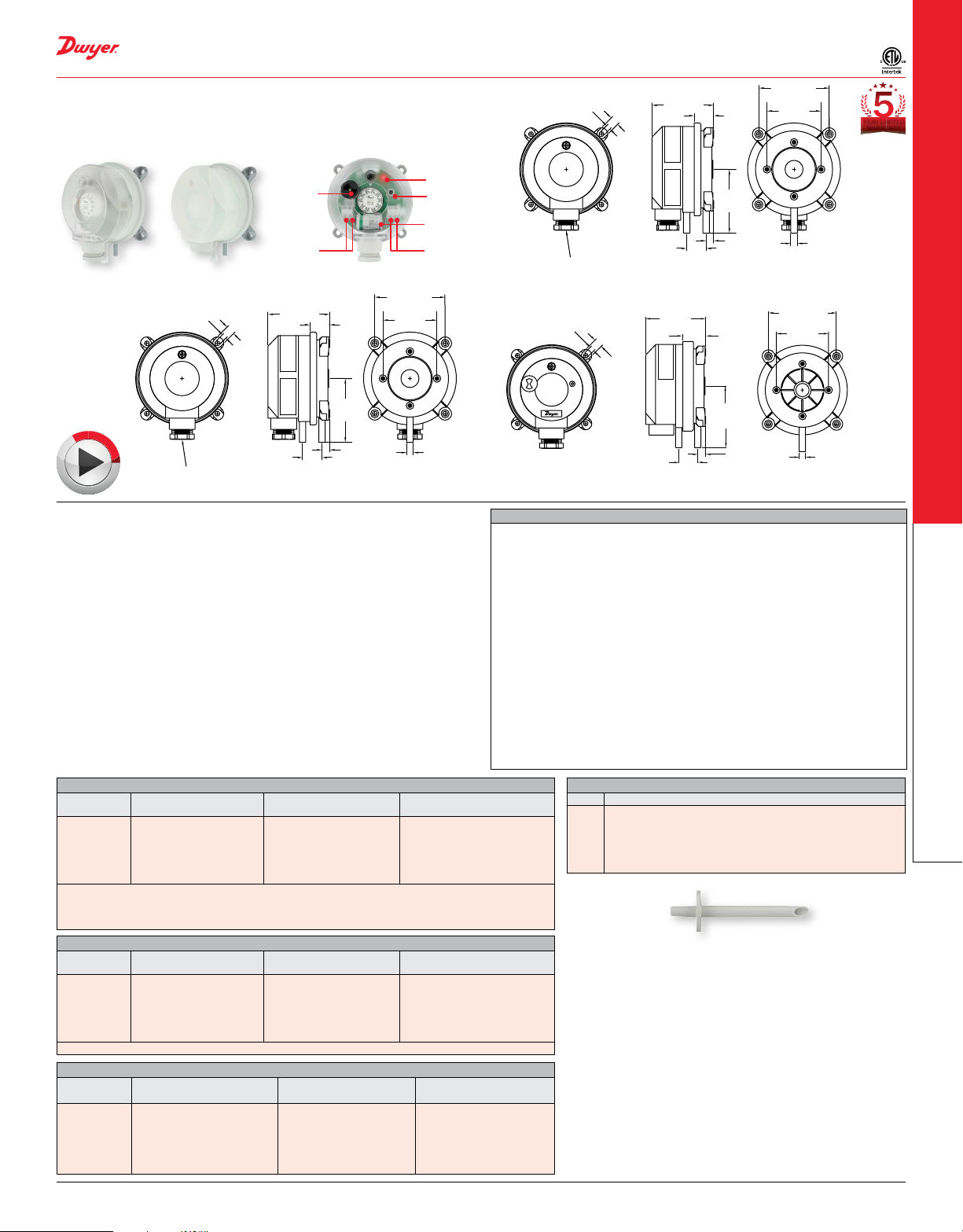
The Series ADPS/EDPS/BDPA HVAC Differential Pressure Switches are designed
for pressure, vacuum, and differential pressures. The dual scaled adjustment knob in
inches water column and pascals allows changes to the switching pressure to be made
without a pressure gage. The ADPS/EDPS/BDPA are available with settings from 0.08
in w.c. (20 Pa) up to 20 in w.c. (5000 Pa). The silicone diaphragm and PA 6.6 body
make the series ADPS ideal for use with air and other noncombustible gases. Series
EDPS models meet UL508 and are constructed of plenum rated plastics. The series
BDPA Adjustable Differential Pressure Alarms offer a versatile range of congurations
allowing utilization of their many features including buzzer and LED notication, and
battery or line powered. The compact size, adjustment knob and low cost make the
ADPS/EDPS/BDPA the perfect choice for HVAC applications.
BENEFITS/FEATURES
• Adjustment knob changes switching pressure easily with a pressure gage reducing
components for application
• Low cost device makes it an excellent solution in BAS and HVAC applications
requiring duct control and monitoring
• Relay contact allows simple integration with DDC or building systems
APPLICATIONS
• Air lter and ventilator monitoring
• Industrial cooling circuits
• Fire-protection damper control
• Ventilation duct monitoring
• Fan heater overheating protection
• Heat exchanger frost protection
MODEL CHART - ADPS
Model
ADPS-08-2-N
ADPS-04-2-N
ADPS-03-2-N
ADPS-05-2-N
ADPS-06-2-N
ADPS-07-2-N
Note: For optional 1/2˝ NPT conduit connection, change -2-N to-1-N. Models that include installer kit
add -C to the end of the model number (-2-N cable gland models only). Installer kit includes two static
tips and 7 ft of PVC tubing. Order installer kit separately with 1/2˝ NPT conduit connection models.
See A-481 in the accessories list. Consult factory for bulk packaging option.
Set Point Range
in w.c. (Pa)
0.08 to 1.20 (20-300)
0.12 to 1.60 (30-400)
0.20 to 2.00 (50-500)
0.80 to 4.00 (200-1000)
2.00 to 10.00 (500-2500)
4.00 to 20.00 (1000-5000)
Approx. Dead Band @
Min Set Point in w.c. (Pa)
0.04 (10)
0.06 (15)
0.08 (20)
0.4 (100)
0.6 (150)
1.0 (250)
MODEL CHART - EDPS
Model
EDPS-08-1-N
EDPS-04-1-N
EDPS-03-1-N
EDPS-05-1-N
EDPS-06-1-N
EDPS-07-1-N
Note: For optional M20 cable gland connection, change -1-N to-2-N.
Set Point Range
in w.c. (Pa)
0.08 to 1.20 (20-300)
0.12 to 1.60 (30-400)
0.20 to 2.00 (50-500)
0.80 to 4.00 (200-1000)
2.00 to 10.00 (500-2500)
4.00 to 20.00 (1000-5000)
Approx. Dead Band @
Min Set Point in w.c. (Pa)
0.04 (10)
0.06 (15)
0.08 (20)
0.4 (100)
0.6 (150)
1.0 (250)
MODEL CHART - BDPA
Model
BDPA-08-2-N
BDPA-04-2-N
BDPA-03-2-N
BDPA-05-2-N
BDPA-06-2-N
BDPA-07-2-N
Set Point Range
in w.c. (Pa)
0.08 to 1.20 (20 to 300)
0.12 to 1.60 (30 to 400)
0.20 to 2.00 (50 to 500)
0.80 to 4.00 (200 to 1000)
2.00 to 10.00 (500 to 2500)
4.00 to 20.00 (1000 to 5000)
Approx. Dead Band @
Min Set Point in w.c. (Pa)
0.04 (10)
0.06 (15)
0.08 (20)
0.4 (100)
0.6 (150)
1.0 (250)
LED
Test/snooze
button
Battery
Contact
output
1-31/32
[50]
Ø15/64
[Ø6]
SPECIFICATIONS
Service: Air and non-combustible, compatible gases.
Wetted Materials: ADPS: Diaphragm material: Silicone; Housing material: POM;
Switch body: PA 6.6; Cover: Polystyrene; EDPS: Diaphragm material: Silicone;
Housing material: Switch body: PA 6.6; Cover: Polystyrene; Materials UL 94 V-0
rated.
Temperature Limits: Process and ambient temperature from -4 to 185°F (-20 to
85°C).
Storage: -40 to 185°F (-40 to 85°C).
Pressure Limits: Max. operating pressure: 40 in w.c. (10 kPa) for all pressure
ranges.
Switch Type: Single-pole double-throw (SPDT).
Electrical Rating: Max. 1.5 A res./0.4 A ind./250 VAC, 50/60 Hz; Max. switching
rate: 6 cycles/min.
Electrical Connections: Push-on screw terminals. M20x1.5 with cable strain relief
or optional 1/2˝ NPT.
Process Connections: 5/16˝ (7.94 mm) outside diameter tubing, 1/4˝ (6.0 mm)
inside diameter tubing.
Enclosure Rating: NEMA 13 (IP54).
Mounting Orientation: Vertically, with pressure connections pointing downwards.
Mechanical Working Life: Over 10
Weight: 4.4 oz (125 g).
Compliance: ETL approved to UL508 and CSA C22.2#14 (EDPS only).
Approx. Deadband @
Max Set Point in w.c. (Pa)
0.05 (12)
0.09 (23)
0.09 (23)
0.5 (130)
0.8 (200)
1.4 (350)
Approx. Dead Band @
Max Set Point in w.c. (Pa)
0.05 (12)
0.09 (23)
0.09 (23)
0.5 (130)
0.8 (200)
1.4 (350)
Approx. Dead Band @
Max Set Point in w.c. (Pa)
0.05 (12)
0.09 (23)
0.09 (23)
0.5 (130)
0.8 (200)
1.4 (350)
CABLE GLAND INSERT
Ø11/64
[Ø4.5]
IP 54
Ø11/64
[Ø4.5]
ACCESSORIES
Model Description
A-288
“L” type metal mounting bracket with screws
A-289
“S” type metal mounting bracket with screws
A-480
Plastic static pressure tip
A-481
Installer kit, includes 2 plastic static pressure tips and 7´
(2.1 m) of PVC tubing
A-489
4˝ straight static pressure tip with ange
Process Tubing Options: See page 453 (Gage Tubing Accessories)
1-31/32
[50]
Ø15/64
[Ø6]
YEAR LIMITED
WARRANTY
21/64
[8.5]
51/64 [18]
2-1/4 [57]
-
+
45/64
[18]
2-21/64
[59]
9/32 [7]
ADPS
21/64
[8.5]
51/64 [18]
[57.5]
[P2] -+ [P1]
7/8
[22]
2-21/64
[59]
19/64 [7.5]
1-31/32
[50]
Ø15/64
[Ø6]
BDPA
6
switching operations.
A-480
DWYER INSTRUMENTS, LLC | dwyer-inst.com
Differential Pressure Switches
45
 Loading...