

Page 1
ECMCS CURRENT SWITCHES
Installation & Operation Instructions
PRECAUTIONS
• This product is not intended to be used for
Life or Safety applications.
• This product is not intended for use in any
hazardous or classified locations.
• The ECM Current Switches must be used on
Insulated Conductors Only!
HIGH VOLTAGE
• Disconnect and lock out all power sources
before installation as severe injury or death
may result from electrical shock due to
contact with high voltage wires.
GENERAL INFORMATION
ACI ECMCS split-core current switches are
designed for use in electronically commutated
motor (ECM) applications in which you are
looking for status for a particular piece of
equipment. ECMs have a unique operating prole
that includes a small standby current when the
motor is powered but not actively spinning
compared to no current draw of traditional PSC
motors.
The ECMCS switches do not require external
power, since the power for the current switch is
induced from the conductor being monitored.
ACI’s ECMCS switch has an adjustable trip level
to set the desired trip level for proper motor
status indication in most ECM applications. ACI
oers a calibration tool that will help assist the
installation process by implementing a visual
indication of the state of the output switch to the
installer.
The ECM current switch can be secured to
the monitored cable using a cable tie and
the integrated cable tie anchor feature of the
housing. The ECMCS switch also comes with an
attachable mounting foot that allows the unit to
be mounted in any position using one Tek screw
or snapped directly on a 35mm DIN rail.
Note: The ECM switch is not intended to monitor
status in VFD motor applications.
Phone: 1-888-967-5224
Website: workaci.com
Mounting
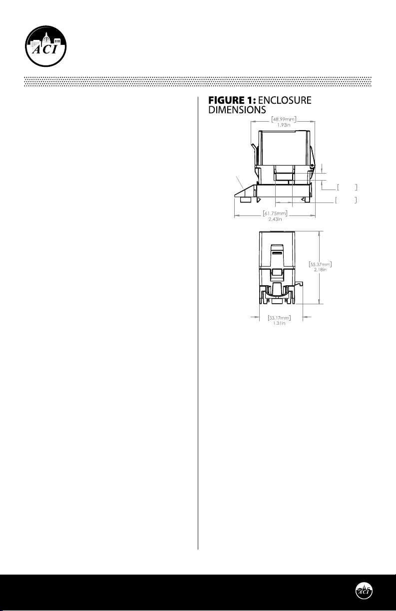
Foot
5.0mm
0.20in
12.5mm
0.49in
BEFORE INSTALLATION
• The ECM current switch is set to its maximum
trip level by the factory.
INSTALLATION INSTRUCTIONS
Make sure that all installations are in compliance
with all national and local electrical codes. Only
qualied individuals that are familiar with codes,
standards, and proper safety procedures for highvoltage installations should attempt installation.
The current switches will not require external
power, since the power for the current switch is
induced from the conductor being monitored.
The ECM switch has multiple mounting options.
The ECM current switch enclosure has a plastic
feature that allows for the monitored current
wire to be cable tied to the enclosure for free
hanging installation applications - See Figure 4
(pg. 2). This will be the preferred method for most
installations.
Alternatively, the current switch product comes
Automation Components, Inc.
2305 Pleasant View Road | Middleton, WI 53562
Phone: 1-888-967-5224 | Website: workaci.com
Page 1
Version: 2.0
I0000951
Page 2
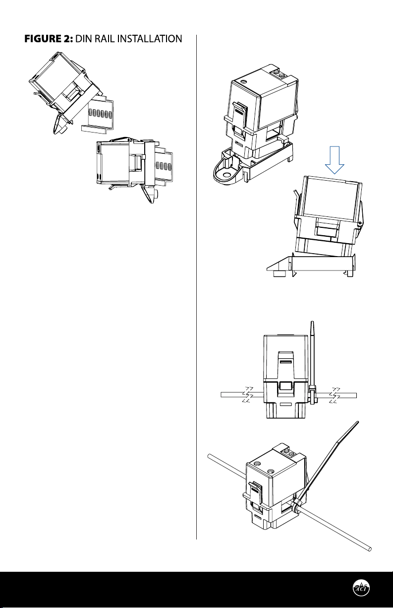
with a detached mounting foot. With the
mounting foot attached to the ECM switch main
body, the enclosure may be mounted in any
position using the one #8 x 3/4” Tek screw through
the hole in the mounting foot. The mounting clip
must be snapped into position- See Figure 3.
Align the front of the ECM Switch (latch) with the
front of the mounting clip (screw mount). Insert
the ECM Switch unit at a slight angle, with the
back of the unit leading down, and push down
to snap into place. Additionally, the enclosure
may be snapped directly on a 35mm DIN rail See Figure 2 (pg. 2). Leave a minimum distance
of 1” (3 cm) between the current switch and any
other magnetic devices such as contactors and
transformers.
FIGURE 3: MOUNTING FOOT
ATTACHMENT
FIGURE 4: WIRE MOUNTING
LATCH OPERATION FOR ECM SERIES
Press down on the side tab and swing the top of
the unit up to open the split core current switch.
Press down firmly on the cover to close the
current switch. An audible “click” will be heard as
the tab slides over the tongue on the base.
CAUTION
Mating surfaces of the magnetic core are
exposed when the sensor is open. Operation can
be impaired if anything prevents good contact
between pole pieces. Visually check the mating
parts of the core before closing the current
sensor.
Automation Components, Inc.
2305 Pleasant View Road | Middleton, WI 53562
Phone: 1-888-967-5224 | Website: workaci.com
Page 2
Version: 2.0
I0000951
Page 3
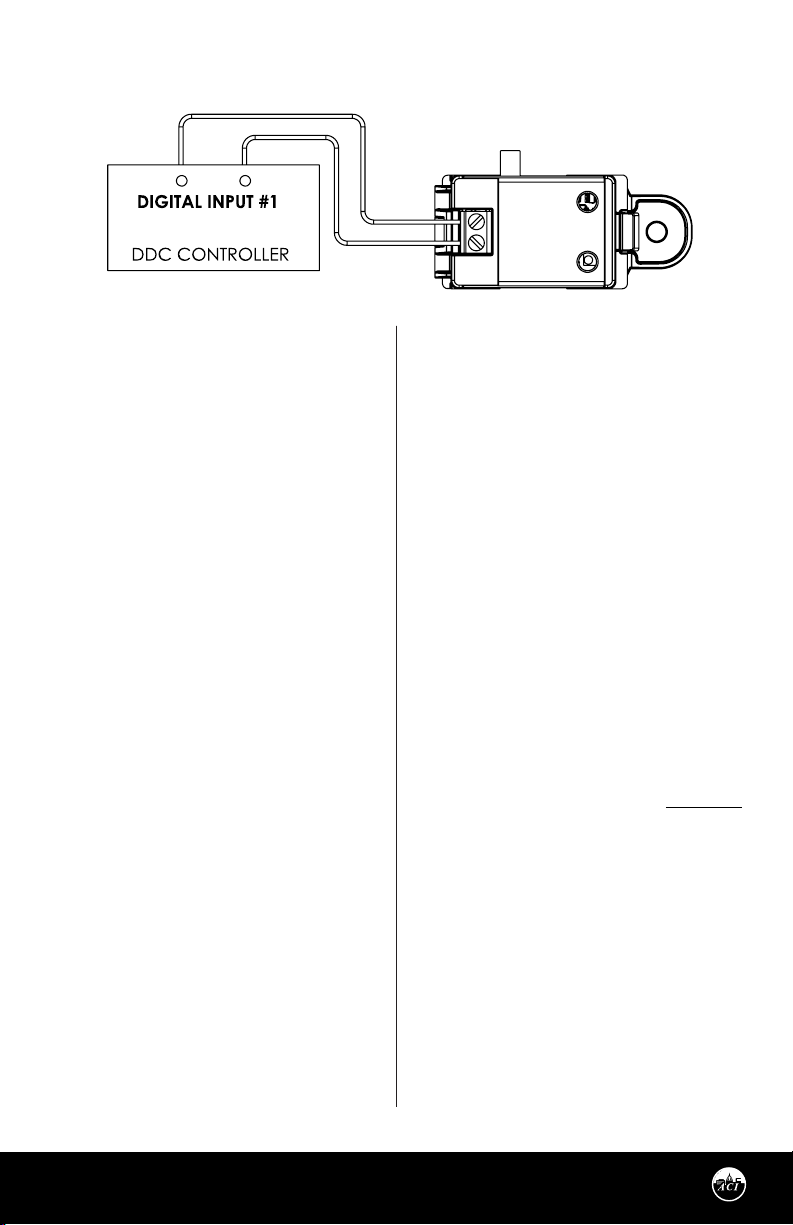
FIGURE 5: DIGITAL CIRCUIT
WIRING INSTRUCTIONS
ACI recommends the use of a two conductor 16
to 22 AWG shielded cable or twisted pair copper
wire only for all current switch applications.
Note: When using a shielded cable, be sure to
connect only (1) end of the shield to ground
at the controller. Connecting both ends of the
shield to ground may cause a ground loop.
When removing the shield from the sensor end,
make sure to properly trim the shield to prevent
any chance of shorting.
The current switch output terminals represent
a solid-state switch for controlling both AC and
DC loads and are not polarity sensitive. Tighten
the screws at the terminal block connections to
the recommended torque of 0.5 to 0.6 Nm (4.43
to 5.31 in-lbs.). The aperture (hole) of the current
switch will handle 10 AWG to 14 AWG wire sizes.
Figure 5 is showing the use of the Go/No Go
Current Switch as a Digital Input to your DDC
Controller.
CHECKOUT
Note: The ECM current switch is set to its
maximum trip level by the factory.
With the ECM current switch installed, turn on
the power source to the ECM and verify that the
ECM current switch has a closed output switch
function when the motor is spinning and an
open output switch function when the motor is
in standby operation—not spinning.
CALIBRATION
If the ECM current switch status indication does
not correctly indicate motor status, use the
following steps to perform the calibration of the
status indication. For switch status indication,
ACI recommends the ECM Trip Adjust Tool be
installed on the switch terminal block. The Trip
Adjust Tool will give LED indication of a closed
switch.
If the Trip Adjust Tool is unavailable, direct
connection to the BMS(Building Management
System) is recommended. Note that the BMS
usually has a slight delay in response time.
Response time must be taken into consideration
when calibrating.
Note: ACI recommends to calibrate the switch
with the EC motor in standby mode.
Clockwise = Decrease Trip Point
Counterclockwise = Increase Trip Point
Set the motor to operate in standby mode (EC
motor is powered, but the motor is not spinning).
If the ECM current switch indicates a standby
status (open output switch):
• Rotate the trip level adjustment screw
Clockwise slowly for the ECM current switch to
respond. Once the ECM current switch changes
to the motor spinning status (closed output
switch), stop rotating.
• Then rotate the adjustment screw very slowly
Counterclockwise until switch changes to the
standby status (open output switch). Try not to
overshoot the rotation at this point.
• Verify correct operation of the ECM current
switch by alternating between motor spinning
and motor standby operation. If you need to
repeat the trip level adjustment, set the motor
to operate in the standby mode again and
rotate the pot CW until the switch changes
to the motor spinning status (closed output
switch), and then very slowly rotate the pot
CCW until the switch changes to the standby
status (open output switch).
Calibration is now complete.
Automation Components, Inc.
2305 Pleasant View Road | Middleton, WI 53562
Phone: 1-888-967-5224 | Website: workaci.com
Page 3
Version: 2.0
I0000951
Page 4

PRODUCT SPECIFICATIONS
Monitored Current Type: AC Current
Maximum AC Voltage: 600 VAC
Operating Frequency Range: 50/60 Hz
Core Style: Split-Core
Sensor Power: Induced from the Monitored Conductor (Use Insulated Conductors only)
Amperage Range: 0 to 25 A
Insulation Class: 600 VAC
Trip Point Style | Adjustable Trip Point Range: Adjustable Trip Point | 0.075 A to 0.50 A
Hysteresis: 10% of Trip Level Current, Typical
Contact Type: Normally- Open “N/O”
Contact Rating: 100 mA Continuous @ 30 VAC/VDC
Contact “On” Resistance | “O” Resistance: < 10 Ohms (when tripped) | > 1 Meg Ohms (Open)
Response Time: < 5 Seconds Typical
Aperture Size (Diameter) | Wire Size: 0.20”(5.0mm) x 0.49”(12.5mm) | Fits 10 AWG to 14 AWG THHN Insulated Wire
DIN Rail Size: 35 mm
Operating Temperature | Humidity Range: 32°F to 140°F (0°C to 60°C) | 10 to 90%, non-condensing
Storage Temperature | RH Range: -40 to 158°F (-40 to 70°C) | 10% to 90% RH, non-condensing
Enclosure Material | Flammability Rating: PC/ABS (Polycarbonate/ABS Blend) | UL94-V0
Wiring Connections: 2 Position Screw Terminal Block (Not Polarity Sensitive)
Wire Size: 16 to 22 AWG (1.31 mm2 to 0.33 mm2) Copper Wires Only
Terminal Block Torque Rating: 4.43 to 5.31 in-lbs. (0.5 to 0.6 Nm)
Minimum Mounting Distance:
Agency Approvals:
Pollution Degree: 2
Environmental: Indoor
Product Dimensions (L x W x H): 1.93" (48.99 mm) x 1.31" (33.17 mm) x 2.18" (55.37 mm)
1” (2.6 cm) between current switch & other magnetic devices (Relays, Contactors,
Transformers)
UL/CUL US Listed (UL 916) Energy Management Equipment (File # E334792), CE,
UKCA, RoHS, WEEE, CAN ICES-3 / NMB-3
WARRANTY
The ACI ECM Current Switch Series are covered by ACI’s Five (5) Year Limited Warranty, which is located in the front of
ACI’S SENSORS & TRANSMITTERS CATALOG or can be found on ACI’s website: www.workaci.com.
W.E.E.E. DIRECTIVE
At the end of their useful life the packaging and product should be disposed of via a suitable recycling centre. Do not
dispose of with household waste. Do not burn.
FCC Compliance Statement
This device complies with part 15 of the FCC Rules. Operation is subject to the following two conditions: (1) This device
may not cause harmful interference, and (2) this device must accept any interference received, including interference
that may cause undesired operation.
10
Page 4
Automation Components, Inc.
2305 Pleasant View Road | Middleton, WI 53562
Phone: 1-888-967-5224 | Website: workaci.com
Version: 2.0
I0000951
 Loading...