

Page 1

Easidew
Advanced Online Hygrometer
User Manual
97621 Issue 1.4
January 2025
Page 2
Please ll out the form(s) below for each instrument that has been purchased.
Use this information when contacting Michell Instruments for service purposes.
Product Name
Order Code
Serial Number
Invoice Date
Installation Location
Tag Number
Product Name
Order Code
Serial Number
Invoice Date
Installation Location
Tag Number
Product Name
Order Code
Serial Number
Invoice Date
Installation Location
Tag Number
Page 3
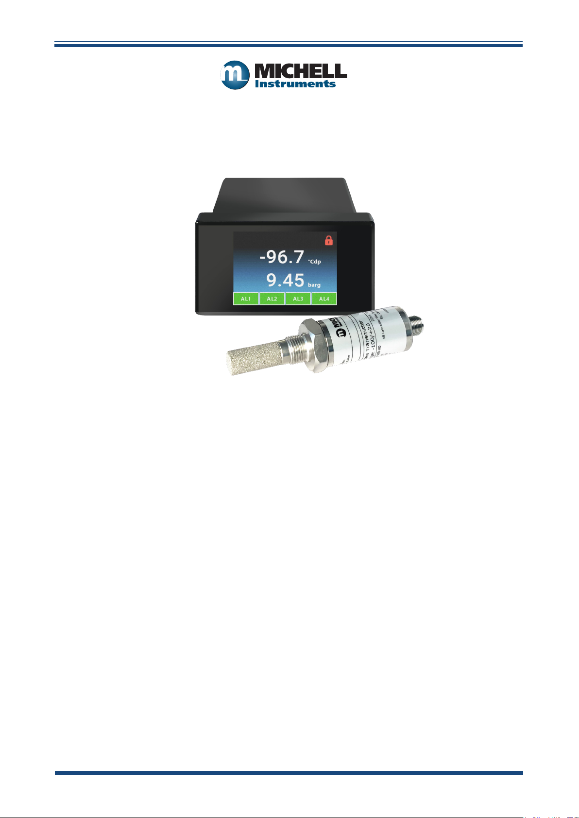
Easidew Advanced Online Hygrometer
For Michell Instruments' contact information please go to
www.ProcessSensing.com
© 2025 Michell Instruments
This document is the property of Michell Instruments Ltd and may not be copied or
otherwise reproduced, communicated in any way to third parties, nor stored in any Data
Processing System without the express written authorization of Michell Instruments Ltd.
Page 4

Easidew Advanced Online Hygrometer Manual
Contents
Safety ................................................................................................................................vi
Electrical Safety ..........................................................................................................vii
Pressure Safety ...........................................................................................................vii
Hazardous Materials (WEEE, RoHS & REACH) ................................................................vii
Repair and Maintenance ..............................................................................................vii
Calibration .................................................................................................................. vii
Safety Conformity .......................................................................................................vii
Abbreviations .................................................................................................................... viii
1 INTRODUCTION ................................................................................................1
1.1 Features ............................................................................................................ 1
2 INSTALLATION ..................................................................................................2
2.1 Unpacking the Instrument ................................................................................... 2
2.2 Easidew Advanced Online Components ................................................................ 3
2.3 Process Monitor Display ...................................................................................... 4
2.3.1 Process Monitor Display Layout ...................................................................... 4
2.3.1.1 Process Monitor Display Resolution ................................................................. 4
2.3.2 Electrical Connections .................................................................................... 5
2.3.2.1 High-Voltage Power Supply Input ................................................................... 5
2.3.2.2 Low-Voltage Power Supply Input (Alternative) ................................................. 6
2.3.2.3 Dew-Point Sensor Modbus RTU over RS485 Digital Input (Required) ................ 7
2.3.2.4 Pressure Sensor Input (Optional) ................................................................... 7
2.3.2.5 Analog Outputs ............................................................................................. 7
2.3.2.6 Modbus RTU Output ...................................................................................... 7
2.3.2.7 Relay Outputs ............................................................................................... 8
2.3.2.8 Transmitter Connections ................................................................................ 8
2.4 Mounting the Process Monitor ............................................................................. 8
2.5 Easidew Transmitter ........................................................................................... 9
2.5.1 Easidew M12 Connector Version ..................................................................... 9
2.5.1.1 Electrical Connections .................................................................................. 10
2.5.1.2 Easidew M12 Cables .................................................................................... 11
2.5.2 Cable Selection for Self-Assembled Cables ..................................................... 11
2.6 Transmitter Mounting ........................................................................................ 12
2.6.1 5/8” 18 UNF Version .................................................................................... 12
2.6.2 3/4” - 16 UNF Version ................................................................................. 12
2.6.3 G1/2” BSPP Version ..................................................................................... 12
2.6.4 Transmitter Mounting – Sample Block .......................................................... 13
2.6.5 Transmitter Mounting – Direct Pipeline Connection ........................................ 14
2.6.6 Transmitter Mounting – With Additional Process Connection Adapter .............. 15
2.7 Mounting the Sample Block and Transmitter ....................................................... 16
2.7.1 Sample Block Gas Connections ..................................................................... 16
3 OPERATION ....................................................................................................18
3.1 Process Monitor Conguration ........................................................................... 18
3.2 Front Panel Conguration Menu Access .............................................................. 18
3.3 Conguration Menu Explained ........................................................................... 20
3.4 Setting Up the Process Monitor Conguration ..................................................... 21
3.4.1 Alarms Conguration ................................................................................... 21
3.4.2 Analog Outputs Conguration ...................................................................... 24
3.4.3 Display Conguration .................................................................................. 26
3.4.4 Input Conguration ..................................................................................... 27
3.4.5 Pressure Conguration ................................................................................ 29
3.4.6 About Menu ................................................................................................ 30
iv 97621 Issue 1.4, January 2025
Page 5

Easidew Advanced Online Hygrometer Manual
4 MAINTENANCE ................................................................................................31
4.1 Maintenance and Calibration ............................................................................ 31
4.2 Fault Conditions ............................................................................................... 31
5 MEASUREMENT GUIDE ....................................................................................32
5.1 Sampling Considerations ................................................................................... 32
5.2 Sampling Hints ................................................................................................. 35
Figures
Figure 1 Easidew Advanced Online Components ........................................................3
Figure 2 Monitor Display in Normal Operation ............................................................4
Figure 3 Electrical Wiring Schematic..........................................................................5
Figure 4 Easidew Transmitter ...................................................................................9
Figure 5 Sensor Connector Installation ....................................................................10
Figure 6 Transmitter Mounting – Sensor Block .........................................................13
Figure 7 Transmitter Mounting – Pipe or Duct ..........................................................14
Figure 8 Transmitter Mounting with Adapter ...........................................................15
Figure 9 Sample Block Gas Connections ..................................................................16
Figure 10 Electrical Wiring Schematic ......................................................................21
Figure 11 Alarm Conguration Screen Explained ........................................................21
Figure 12 Analog Outputs Conguration Screen Explained ..........................................24
Figure 13 Display Conguration Screen Explained ......................................................26
Figure 14 Input Conguration Screen Explained .........................................................27
Figure 15 Installation Location .................................................................................33
Figure 16 Installation Location .................................................................................33
Figure 17 Material Permeability Comparison ..............................................................35
Figure 18 Dead volume ............................................................................................36
Appendices
Appendix A Technical Specications ..............................................................................39
Appendix B Process Monitor Register Map ..................................................................... 43
Appendix C Quality, Recycling & Warranty Information ................................................... 53
Appendix D Return Document & Decontamination Declaration ........................................ 55
Michell Instruments v
Page 6
Easidew Advanced Online Hygrometer Manual
!
!
Safety
The instrument is designed to be completely safe when installed and operated correctly in accordance
with the information provided in this manual.
This manual contains all the required information to install, operate and maintain this product. Prior
to installation and use of this product, this entire manual should be read and understood. Installation
and operation of this product should be carried out by suitably competent personnel only. The
installation and operation of this product must be in accordance with the instructions provided and
according to the terms of any associated safety certicates. Incorrect installation and use of this
product other than those described in this manual and other than its intended purpose will render
all warranties void.
This product meets the essential protection requirements of the relevant EU & UK directives. Further
details of applied directives may be found in the product specication.
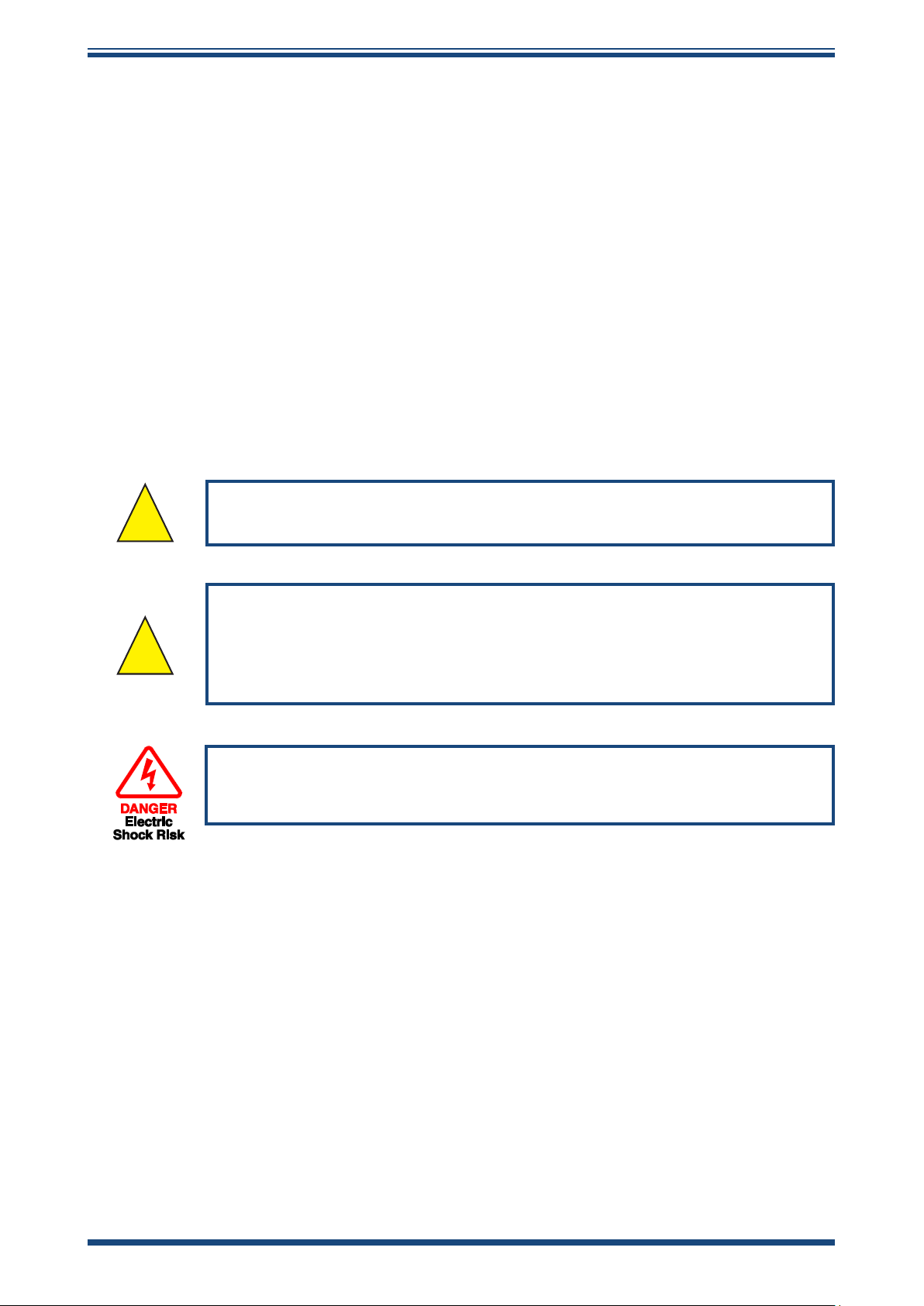
Electricity and pressurized gas can be dangerous. This product must be installed and operated only
by suitable trained personnel.
No user serviceable parts inside
Where this hazard warning symbol appears in the following
sections, it is used to indicate areas where potentially hazardous
operations need to be carried out and where particular attention to
personal and personnel safety must be observed.
Where this symbol appears in the following sections it is used to
indicate areas of potential risk of electric shock.
This product is intended for use only under the following conditions:
a. indoor use
b. altitude up to 2 000 m
c. temperature 5 °C...40 °C
d. maximum relative humidity 80 % for temperatures up to 31 °C decreasing
linearly to 50 %, relative humidity at 40 °C
e. MAINS supply voltage uctuations up to ±10 % of the nominal voltage
f. TRANSIENT OVERVOLTAGES up to the levels of OVERVOLTAGE CATEGORY ll
g. TEMPORARY OVERVOLTAGES occurring on the MAINS supply
h. applicable POLLUTION DEGREE 2 of the intended environment
vi 97621 Issue 1.4, January 2025
Page 7

Easidew Advanced Online Hygrometer Manual
Electrical Safety
Ensure electrical safety is complied with by following the directions provided here and observing all
local operation & installation requirements at the intended location of use.
This product is completely safe when using any options and accessories supplied by the manufacturer
of this product for use with it. Refer to Section 2 (Installation) of this manual for further details.
Pressure Safety
For this product to operate satisfactorily, pressurized gas must be connected to it. Observe all the
information contained within this manual and all local operation & installation requirements at the
intended location of use. Refer to Section 2 (Installation) of this manual for further details.
Hazardous Materials (WEEE, RoHS & REACH)
This product does not contain or release any prohibited chemicals listed on the SVHC (Substances
of Very High Concern) Candidate List. During the intended normal operation of this product it is not
possible for the user to come into contact with any hazardous materials. This product is designed to
be recyclable except where indicated.
Repair and Maintenance
The instrument must be maintained either by the manufacturer or an accredited service agent. For
contact information visit the website at www.ProcessSensing.com.
Calibration
Periodic re-calibration is recommended in order to maintain the highest quality of measurement in
your application. Michell Instruments recommends that you have your Easidew M12 transmitter recalibrated annually unless it is used in a mission-critical application or in a contaminated environment,
in which case the calibration interval should be reduced accordingly.
Michell Instruments can oer a variety of re-calibration and exchange transmitter schemes to suit
your specic needs. A local representative will be pleased to provide detailed custom advice.
Safety Conformity
This product meets the essential protection requirements of the relevant EU & UK directives. Further
details of applied standards may be found in Appendix C.
Michell Instruments vii
Page 8

Abbreviations
The following abbreviations are used in this manual:
AC alternating current
atm pressure unit (atmosphere)
barg pressure unit (=100 kP or 0.987 atm)
ºC degrees Celsius
ºF degrees Fahrenheit
DC direct current
dp dew point
ft foot (feet)
g gram(s)
Hz Hertz
“ inch(es)
lb pound
l/min liters per minute
m meter(s)
µm micro-meter
mA milliampere
max maximum
min minute(s)
MPa megapascal (Pascals x106)
Nl/min normal liters per minute
Nm Newton meter
ppmV parts per million (by volume)
rh relative humidity
scfh standard cubic feet per hour
V Volts
Ω Ohms
Easidew Advanced Online Hygrometer Manual
viii 97621 Issue 1.4, January 2025
Page 9

Easidew Advanced Online Hygrometer Manual
1 INTRODUCTION
The Easidew Advanced Online Hygrometer is easy to install and congure; this versatile
touch screen hygrometer can measure and display dew point and moisture content and
indicate pressure. This display provides analog, digital and 4 programmable relay alarm
outputs with front screen or software app display conguration.
It has been developed as a premium-performance hygrometer system for use in a wide
variety of applications.
It can display data in °C or °F dew point, ppmV, lb/mmscf or g/m3, from -110 up to +20 °C
(-166 up to +68 °F), at pressures up to 525 bar (7614 psi).
To calculate moisture content from dew point, it is necessary to know the system pressure.
This hygrometer can either compensate for pressure change by using a live pressure
sensor input, or accept a xed pressure input value.
INTRODUCTION
1.1 Features
The Easidew Advanced Online Hygrometer oers customers the following features:
• Measurement range -110...+20 °C (-166...+68 °F) dew point
• Dew point or moisture content output
• Accuracy ±1 °C (±1.8 °F) dew point
• Pressure indication and compensation
• Touch screen display conguration
• 3 x 4...20 mA output and 4 relay outputs
• Modbus RTU over RS485 output
• Choice of AC or DC Power Supply
• Sample block and cable included
• Traceable 13-point calibration certicate
Michell Instruments 1
Page 10

INSTALLATION
!
Easidew Advanced Online Hygrometer Manual
2 INSTALLATION
It is essential that the connection of electrical and gas supplies
to this instrument be undertaken by competent personnel.
2.1 Unpacking the Instrument
The Easidew instruments and accessories are packed into one box which should be
unpacked carefully. Save all the packing materials for the purpose of returning the
instrument for recalibration or any warranty claims.
When unpacking the Easidew M12 Dew-Point Transmitter from its individual packaging,
take care not to handle the sensor guard.
The Process Monitor is packed in a cardboard box, together with its xing clamps.
NOTE: For environmental and operating conditions, refer to Appendix A.
NOTE: Packaging specications are subject to continuous improvement, as
we reduce our use of plastics and move to cardboard packing systems.
2 97621 Issue 1.4, January 2025
Page 11
Easidew Advanced Online Hygrometer Manual
1
5
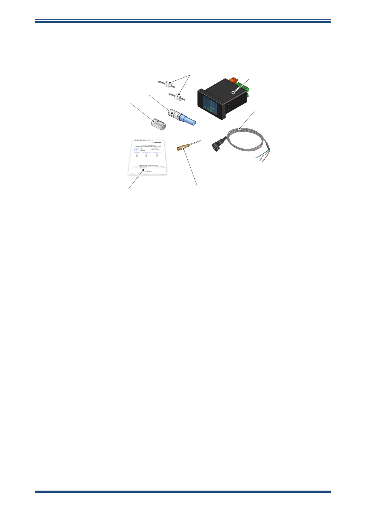
2.2 Easidew Advanced Online Components
On delivery please check that all the following standard components are present in the
packing box. Report any shortages to Michell Instruments, immediately.
7
6
INSTALLATION
2
3
97211 Issue 01, May 2010
Figure 1
Easidew Advanced Online Components
1. Monitor clamps (2 o)
2. Easidew Advanced Online Hygrometer
3. Transmitter cable assembly
4. Screwdriver
5. Calibration certicate
6. Sample block
7. Easidew M12 Transmitter
4
Michell Instruments 3
Page 12
INSTALLATION
Easidew Advanced Online Hygrometer Manual
2.3 Process Monitor Display
The display within the Process Monitor is an LCD 320 x 240 pixel software driven, touch
screen color display.
2.3.1 Process Monitor Display Layout
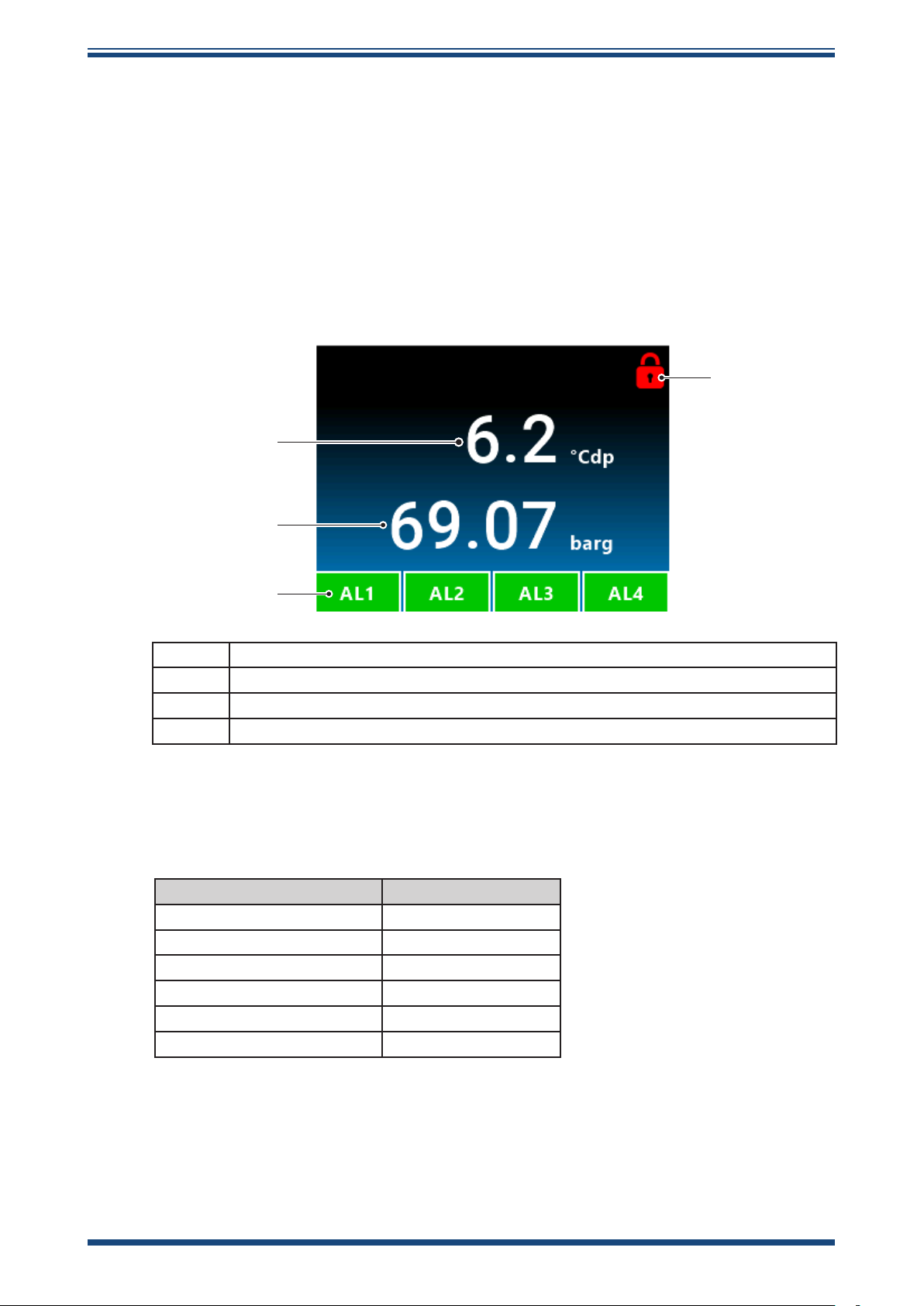
In normal operation, the display screen will appear as below.
The display shows a moisture or pressure value, the status of four alarms and a display
locked/unlocked symbol, which is all explained in detail in
1
Figure 2
below.
4
2
3
1 Dew Point or Moisture Content value referenced to its congured scale
2 Pressure Indication value or ppmV referenced to its congured pressure scale
3 Alarm Status of the 4 relay outputs
4 Security code protected Unlock button to access the conguration menu
Figure 2
Monitor Display in Normal Operation
2.3.1.1 Process Monitor Display Resolution
Display Resolution Decimal Places
-110...+20 °C dew point 1
1,000...10,000 ppm
100...1,000 ppm
Below 100 ppm
V
V
V
Llbmmscf 2
3
mgm
1
2
3
2
4 97621 Issue 1.4, January 2025
Page 13
Easidew Advanced Online Hygrometer Manual
2.3.2 Electrical Connections
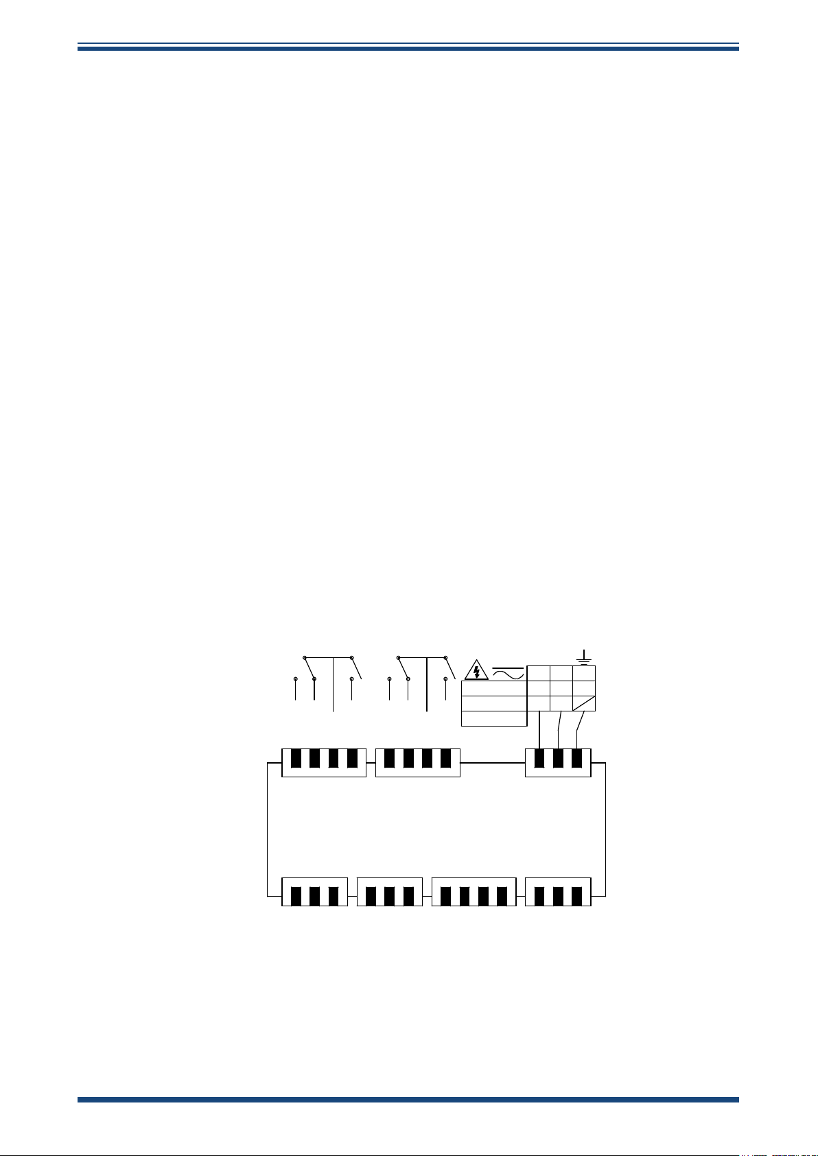
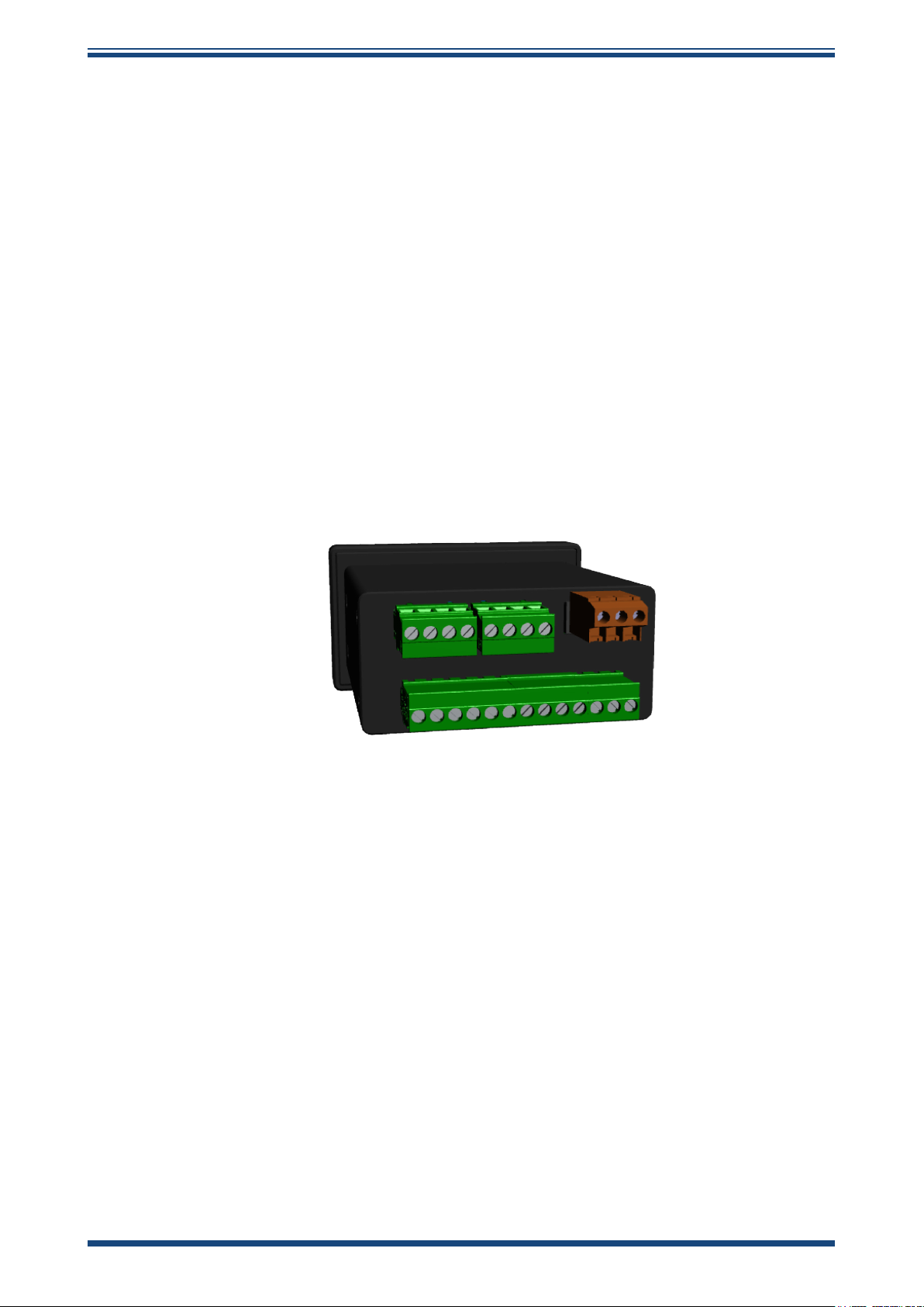
Electrical connections to the Easidew Online system are as follows:
• AC power supply input, 85...265 V AC (7.8 VA)
• Alternative low-voltage DC input is also available: 18...30 V DC (170 mA
@24 V DC)
• Dew-Point Sensor Modbus RTU over RS485 digital input (24 V DC loop
power provided by monitor)
• Pressure Sensor 2-wire 4...20 mA current loop (24 V DC loop power
provided by monitor) input (optional)
• Modbus RTU over RS485 digital communications interface
• 3 x programmable 4...20 mA analog outputs for assigning to dew point,
moisture content and pressure parameters
• 2 x Form A, 2 x Form C Namur compliant programmable relay outputs for
process and fault conditions
INSTALLATION
The power supply voltage is indicated on the connection detail label located on the
Process Monitor. As the Process Monitor is provided for continuous operation, it does
not have an ON/OFF switch.
The power supply to the Process Monitor may be one of the following, dependent on
the type ordered.
NOTE: Connect 0 V to local or remote Earth depending upon installation.
2.3.2.1 High-Voltage Power Supply Input
AL3 NO
AL3 NC
COM
AL4 NO
24 23 22 21 20 19 18 17 16 15 14
Dew-Point RS485Analog Out
1
23 456 78910 111213
Pressure /
Temperature
AL1 NO
AL1 NC
COM
85-265 VAC
18-30 VDC
7.8 VA Max
AL2 NO
16 15
LNE
+V
14
0V
PowerAlarms 3/4 Alarms 1/2
A
B
+24V
Signal / A
Figure 3
+24V
0V
Signal
0V
OUT 1
OUT 2
OUT 3
Electrical Wiring Schematic
B
0V
For high-voltage powered display
• 85...265 V AC 50/60 Hz
Michell Instruments 5
Page 14

INSTALLATION
Easidew Advanced Online Hygrometer Manual
It is essential that the connection of electrical supplies to this
instrument is undertaken by competent personnel.
Connect the power supply to the monitor as shown in
PIN 14 – Earth
PIN 15 – Neutral
PIN 16 – Live
2.3.2.2 Low-Voltage Power Supply Input (Alternative)
For low-voltage DC powered display
• 18...30 V DC
Connect the power supply to the DC version Process Monitor as shown in
above.
PIN 15 – 0V DC
PIN 16 – 18...30 V DC
Figure 3
above.
Figure 3
6 97621 Issue 1.4, January 2025
Page 15

Easidew Advanced Online Hygrometer Manual
2.3.2.3 Dew-Point Sensor Modbus RTU over RS485 Digital Input (Required)
INSTALLATION
For AC or DC voltage powered display version
Connect the Dew-Point Sensor to the Process Monitor as shown in
PIN 1 – +24 V DC Power
PIN 2 – RS485 A digital comms
PIN 3 – RS485 B digital comms
PIN 6 – 0 V DC Power
2.3.2.4 Pressure Sensor Input (Optional)
For AC or DC voltage powered display version
Connect the Pressure Sensor to the monitor as shown in
PIN 4 – +24 V DC Power
PIN 5 – 4...20 mA signal return
PIN 6 – 0 V DC Power
2.3.2.5 Analog Outputs
For AC or DC voltage powered display version
Figure 3
Figure 3
.
.
PIN 7 – 4...20 mA Current Source Output 1
PIN 8 – 4...20 mA Current Source Output 2
PIN 9 – Common
PIN 10 – 4...20 mA Current Source Output 3
2.3.2.6 Modbus RTU Output
For AC or DC voltage powered display versions
PIN 11 – RS485A digital comms
PIN 12 – RS485B digital comms
PIN 13 – 0 V DC Power
Michell Instruments 7
Page 16
INSTALLATION
2.3.2.7 Relay Outputs
For AC or DC voltage powered display versions, the relay outputs are as shown in
Figure 3
Alarms 1/2
PIN 17 – AL2 normally open
PIN 18 – Common
PIN 19 – AL1 normally closed
PIN 20 – AL1 normally open
Alarms 3/4
PIN 21 – AL4 normally open
PIN 22 – Common
PIN 23 – AL3 normally closed
PIN 24 – AL3 normally open
2.3.2.8 Transmitter Connections
.
Easidew Advanced Online Hygrometer Manual
Connect the Easidew M12 dew-point sensor as shown in the table in
2.4 Mounting the Process Monitor
The Process Monitor is designed for panel mounting and requires a panel cut-out of 44
x 92 mm (1.73 x 3.62”). The recommended panel thickness is 2...5 mm (0.08...0.2”).
To mount the unit, proceed as follows:
Figure 3
.
1. Pass the Process Monitor through the front of the panel.
2. Support the Process Monitor and attach mounting xing brackets
onto the side of the monitor.
3. Tighten the xing screw nger tight, against the back of the panel.
Recommended maximum torque is 30 cNm using a 1.5 mm Allen
key.
4. Ensure the Process Monitor is sitting ush to the front of the panel
and tighten the xing screws evenly against the back of the panel.
Caution: Do not overtighten the screws as this could cause the case to crack.
8 97621 Issue 1.4, January 2025
Page 17
Easidew Advanced Online Hygrometer Manual
2.5 Easidew Transmitter
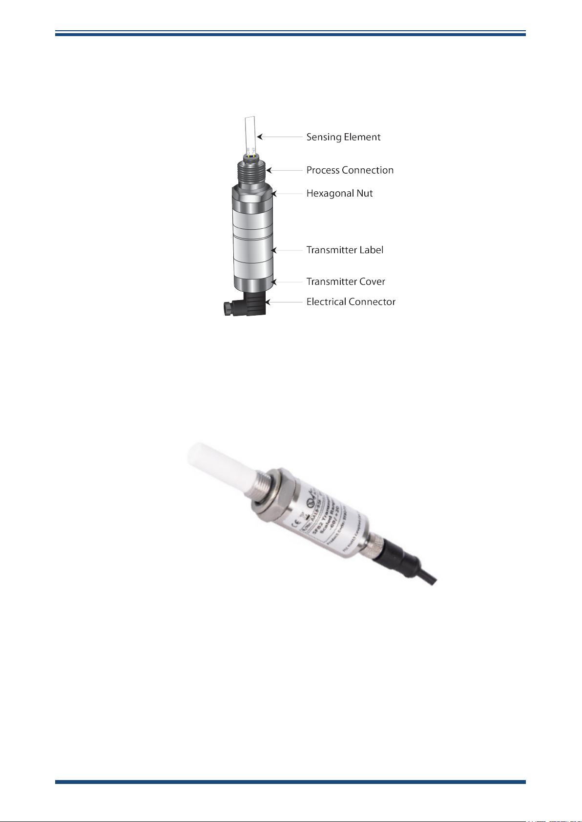
NOTE: The transmitter’s sensing element is shown for illustration purposes
only. Please keep the guard tted at all times, if possible.
INSTALLATION
Figure 4
2.5.1 Easidew M12 Connector Version
The following sections apply to the M12 connector version of the transmitter shown
below.
Easidew Transmitter
Michell Instruments 9
Page 18
INSTALLATION
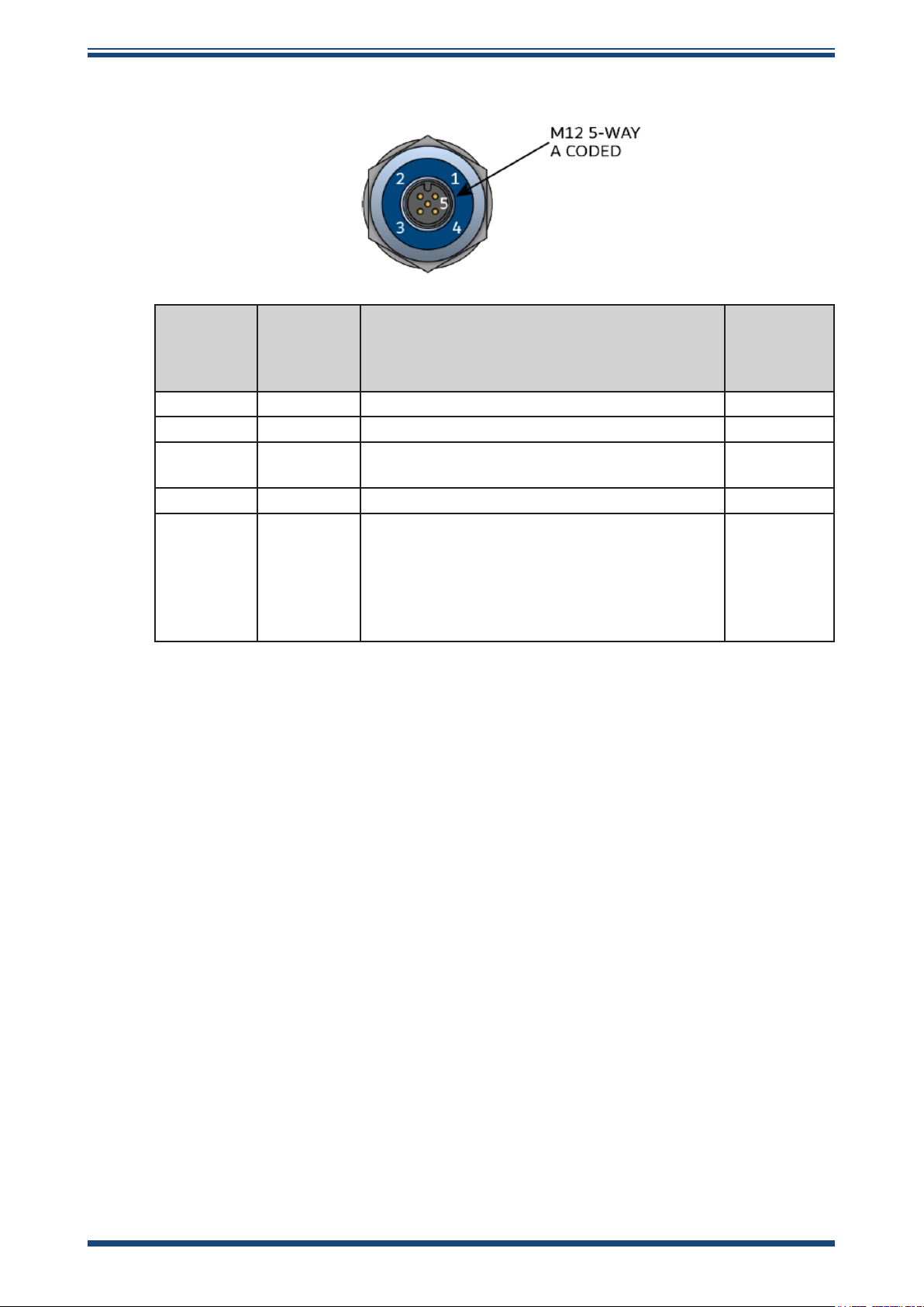
2.5.1.1 Electrical Connections
Easidew Advanced Online Hygrometer Manual
Sensor
Connector
Pin
1 Brown Modbus A 2
2 White Modbus B 3
3 Blue 4...20 mA Signal Return (Power Supply -ve)
4 Black Power Supply +ve 1
M12
connector
sensor
housing
NOTE: The sensor cable is supplied as standard. Replacement pre-wired cables
can be obtained by contacting your local Michell Instruments representative
or assembled by the user according to instructions in the following section.
Michell
Standard
Conductor
Color
Grey Ground, Cable Screen Connection
Function Process
(not used – see note)
This wire directly connects to the metal casing
of the transmitter, but not to the transmitter
electronics, and is intended for cable screening
only.
Figure 5
Sensor Connector Installation
Monitor
Connection
Pin No.
6
Selected
ground
connection
point
NOTE: The sensor transmits its output to the Process Monitor via the RS485
Modbus RTU Communications signal on Pins 1 and 2.
10 97621 Issue 1.4, January 2025
Page 19

Easidew Advanced Online Hygrometer Manual
2.5.1.2 Easidew M12 Cables
The cable connector should be installed by aligning the locating pin on the transmitter
with the slot on the cable. The connector can then be pushed into place and rotated
until nger tight.
Cables with moulded M12 connectors are available from Michell Instruments in the
following lengths:
• 2 m
• 5 m
• 10 m
The other end of the sensor cable is unterminated, for straightforward connection into
the Process Monitor.
If longer cable runs are required, o-the-shelf 5-pin M12 cables can be connected
between the Easidew M12 Transmitter and the Process Monitor.
INSTALLATION
2.5.2 Cable Selection for Self-Assembled Cables
It is recommended to use 4-core screened cable. For short runs, a cable with individual
conductor sizes of 24 AWG / 0.21mm2 would be a typical choice.
Michell Instruments 11
Page 20

INSTALLATION
2.6 Transmitter Mounting
2.6.1 5/8” 18 UNF Version
1. Remove the protective cover and desiccant capsule from the transmitter
and retain for future use
2. Prevent any contamination of the sensor before installation by handling the
transmitter by the main body only, avoiding contact with the sensor guard.
3. Pass the bonded seal over the 5/8”- 18 UNF mounting thread.
4. Screw the transmitter into the sampling location or sample block by hand
using the wrench ats only. DO NOT grip and twist the sensor cover
when installing the sensor.
5. When installed, fully tighten using a wrench to a torque setting of 30.5
Nm (22.5 ft-lbs)
2.6.2 3/4” - 16 UNF Version
Easidew Advanced Online Hygrometer Manual
1. Remove the protective cover and desiccant capsule from the transmitter
and retain for future use.
2. Prevent any contamination of the sensor before installation by handling the
transmitter by the main body only, avoiding contact with the sensor guard.
3. Ensure that the O-ring is seated in the recess at the top of the transmitter
body.
4. Screw the transmitter into the sampling location or sample block by hand
using the wrench ats only. DO NOT grip and twist the sensor cover
when installing the sensor.
5. When installed, fully tighten using a wrench to a torque setting of 40 Nm
(29.5 ft-lbs).
2.6.3 G1/2” BSPP Version
1. Remove the protective cover and desiccant capsule from the transmitter
and retain for future use
2. Prevent any contamination of the sensor before installation by handling the
transmitter by the main body only, avoiding contact with the sensor guard.
3. Pass the bonded seal over the G1/2” mounting thread.
4. Screw the transmitter into the sampling location or sample block by hand
using the wrench ats only. DO NOT grip and twist the sensor cover
when installing the sensor.
5. When installed, fully tighten using a wrench to a torque setting of 30.5
Nm (22.5 ft-lbs)
12 97621 Issue 1.4, January 2025
Page 21
Easidew Advanced Online Hygrometer Manual
2.6.4 Transmitter Mounting – Sample Block
The following procedure must be carried out by a
qualied installation engineer.
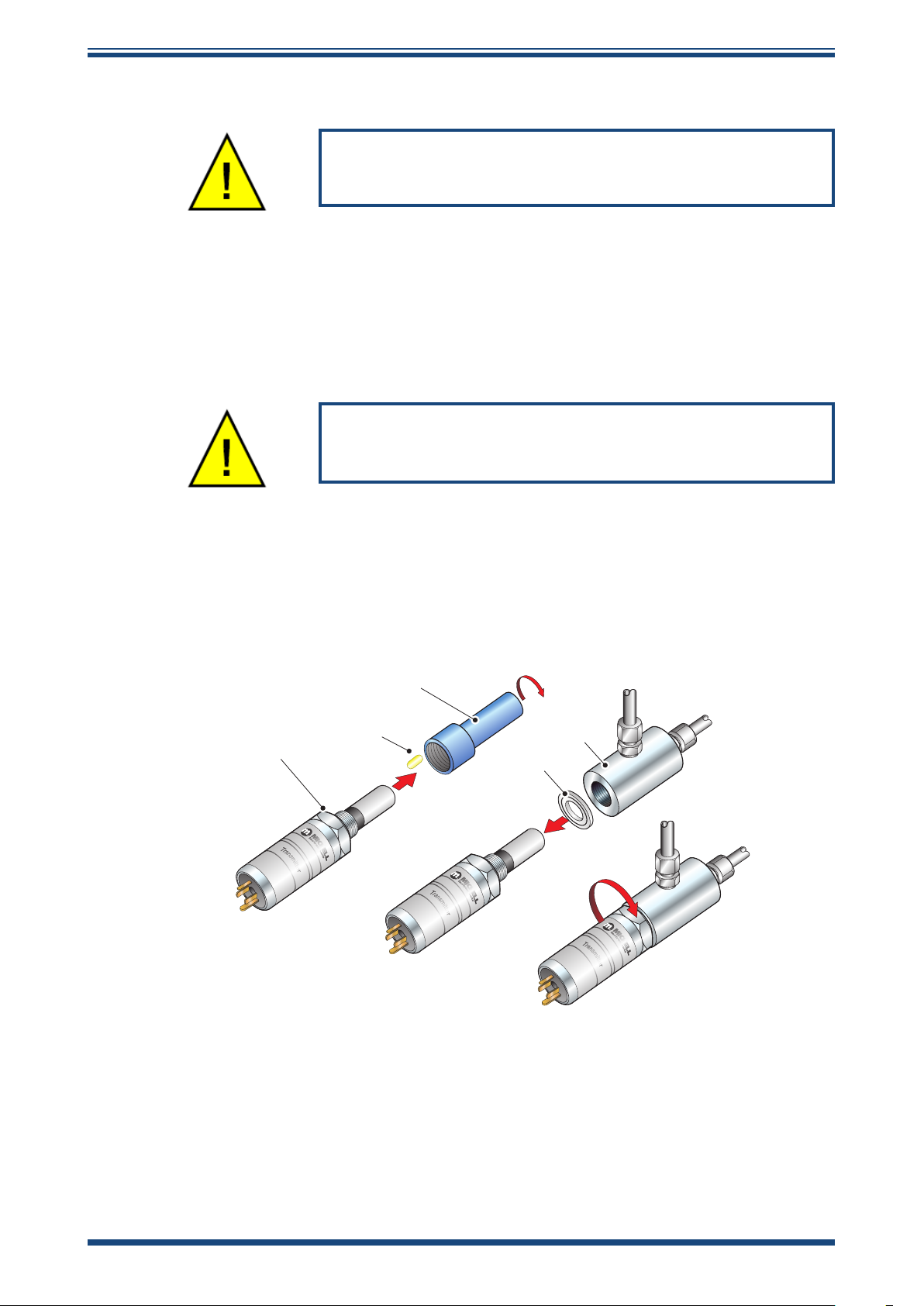
To mount the transmitter into the sensor block (preferred method), proceed as follows,
referring to
1. Ensure that the protective cover (2), and its desiccant capsule (2a), have
been removed from the tip of the transmitter.
2. Fit the bonded seal (4) over the threaded part of the transmitter body.
Figure 6.
WARNING: Under no circumstances should the sensor
guard be handled with the ngers.
INSTALLATION
3. Screw the transmitter (1) into the sample block (3) and tighten to the
recommended torque setting. NOTE: Use the ats of the hexagonal
nut and not the sensor body.
4. Fit the transmitter cable/connector assembly to the plug located on the
base of the transmitter and tighten the xing screw (see Section 2.5).
2
2a
1
3
4
Figure 6
Transmitter Mounting – Sensor Block
Michell Instruments 13
Page 22
INSTALLATION
Easidew Advanced Online Hygrometer Manual
2.6.5 Transmitter Mounting – Direct Pipeline Connection
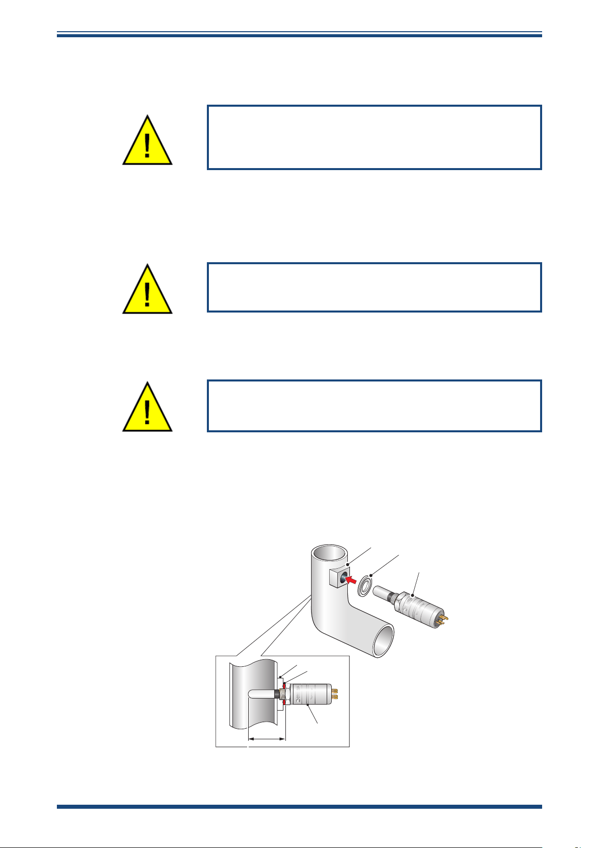
The transmitter may be directly mounted into a pipe or duct, as shown in
Figure 7.
CAUTION: Do not mount the transmitter too close to the
bottom of a bend where any condensate in the pipeline
might collect and saturate the probe.
The pipe or duct will require a thread to match the transmitter body thread. Fixing
dimensions are shown in
Figure 7
. For circular pipework, to ensure the integrity of a
gas tight seal, a mounting ange will be required on the pipework in order to provide a
at surface to seal against.
The following procedure must be carried out by
competent personnel.
1. Ensure that the blue protective cover (and its desiccant capsule) has been
removed from the tip of the transmitter.
WARNING: Under no circumstances should the
sensor guard be handled with the ngers.
2. Fit a bonded seal (2) over the threaded part of the transmitter body.
3. Screw the transmitter (3) into the pipe (1). Tighten enough to obtain a
gas tight seal. (Torque will depend upon the pipeline material.) NOTE: Do
not overtighten or the thread on the pipework may be stripped.
1
2
3
1
2
3
Figure 7
48mm
Transmitter Mounting – Pipe or Duct
14 97621 Issue 1.4, January 2025
Page 23
Easidew Advanced Online Hygrometer Manual
2.6.6 Transmitter Mounting – With Additional Process Connection Adapter
INSTALLATION
!
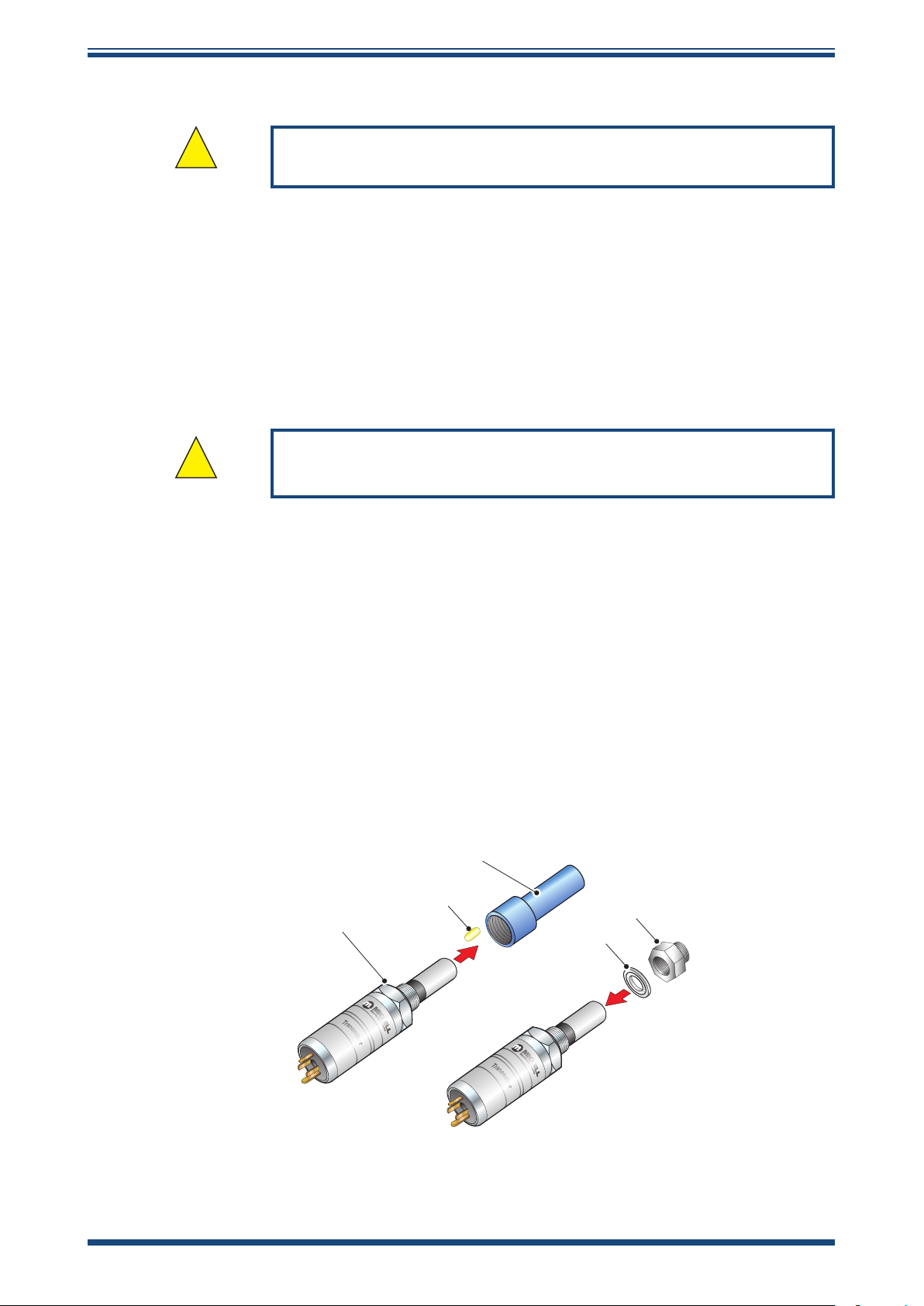
To mount the adapter into the transmitter, proceed as follows (see
1. Ensure that the protective cover (2), and its desiccant capsule (2a), have
been removed from the tip of the transmitter.
2. Fit the bonded seal (3) over the threaded part of the transmitter body.
3. Screw the adapter (4) onto the threaded part of the transmitter and tighten
to torque settings recommended in Sections 2.6.1...2.6.3. NOTE: Use the
ats of the hexagonal nut and not the sensor body.
!
4. Screw the transmitter (1) with its seal (3) and adapter (4) into the sample
block (see Section 2.6.4) or pipeline (see Section 2.6.5) and fully tighten
using a wrench until the seal is fully compressed and to the following torque
settings:
The following procedure must be carried out by a qualied
installation engineer.
Figure 8
WARNING: Under no circumstances should the sensor guard be
handled with the ngers.
):
G 1/2” BSP 56 Nm (41.3 ft-lbs)
3/4” - 16 UNF 40 Nm (29.5 ft-lbs)
1/2” NPT Use a suitable sealant e.g. PTFE tape using the
correct taping procedures
NOTE: Use the ats of the hexagonal nut and not the sensor body.
2
2a
4
1
3
Figure 8
Transmitter Mounting with Adapter
Michell Instruments 15
Page 24
INSTALLATION
Easidew Advanced Online Hygrometer Manual
2.7 Mounting the Sample Block and Transmitter
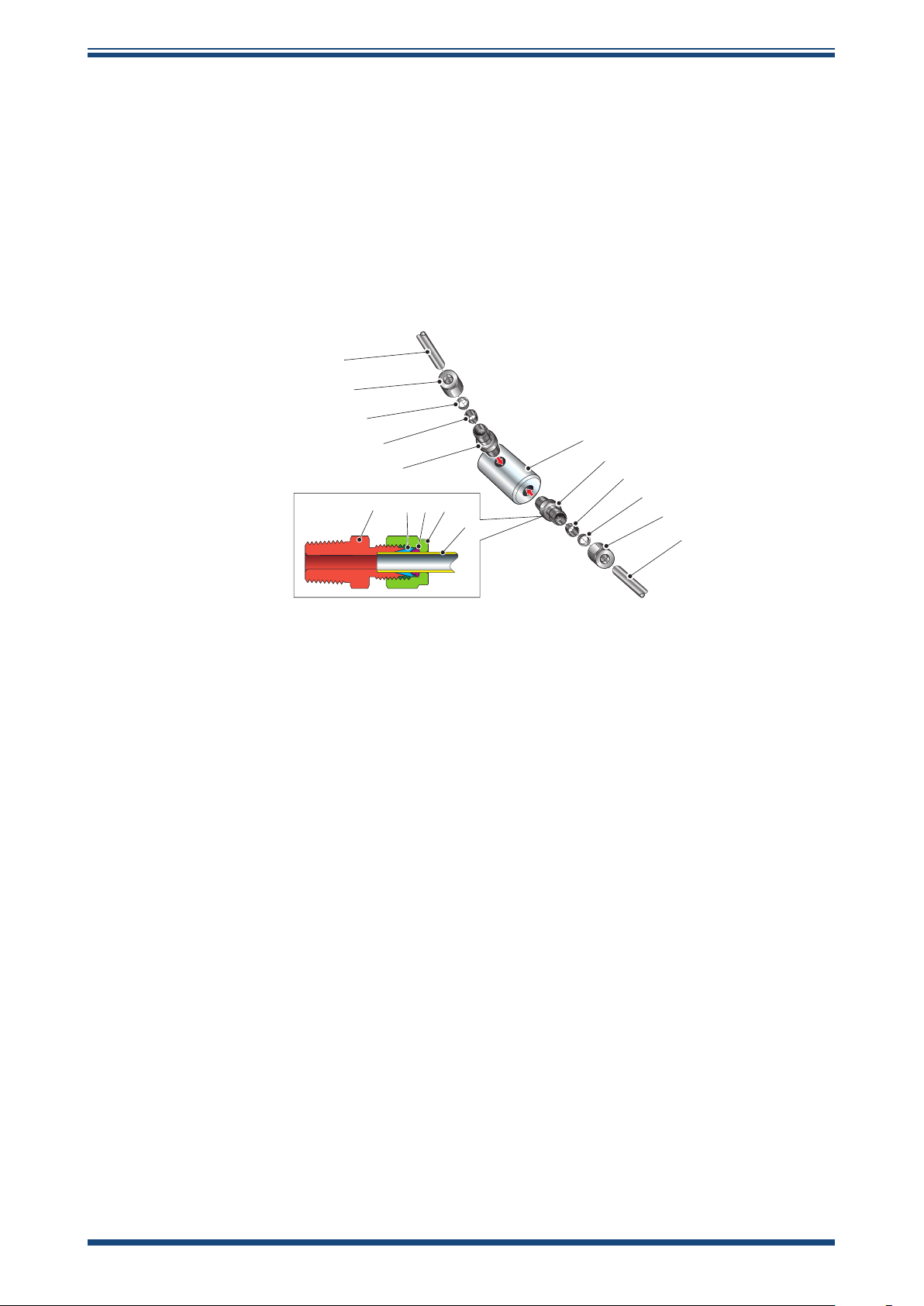
2.7.1 Sample Block Gas Connections
Sample gas connections are made to the Gas In and Gas Out ports on the sample block
(see
Figure 9).
for connection purposes the ports are interchangeable).
Normally, connections are made via stainless steel pipework, in which case the sensor
block/transmitter assembly will be self supporting. If Teon tubing is used it may be
necessary to support the assembly with a body clip.
Either port on the sample block may be used as the Gas Input port (i.e.
1
2
3
4
5
2345
1
6
5
4
3
2
1
Figure 9
Sample Block Gas Connections
Both the Input and Output gas connections are ⅛” NPT. It is recommended that both
the Gas Input and Output connections are made made via ⅛” NPT to 6mm or ⅛” NPT
to ¼” stainless steel tube adaptors (2...5 –
Figure 9
). The method of connection to the
sensor block (6) is as follows:
NOTE: The following description relates to 6mm tube xings. The sample
block ports are both ⅛” NPT female process connections. Tube adaptors
are not supplied with the equipment but can be obtained by contacting your
local distributor or Michell Instruments (see www.ProcessSensing.com for
details).
1. Cut a suitable length of 6mm (¼” U.S.) stainless steel tubing (1) to the
correct length and, if necessary, bend to shape to suit the location of the
sensor block assembly. NOTE: To facilitate ease of connection to the
port, at least 75 mm (3”) of the tubing coming out of the Gas In
port must be straight.
2. Clean o any burrs or metal shavings adhering to the tubing.
3. Screw the ⅛” NPT (¼” U.S.) NPT Swagelok adaptor (5) into the ⅛” NPT
(¼” U.S.) NPT inlet port in the sensor block (6) and tighten to a torque
setting of 35 Nm (25 lbf-ft).
4. Pass the stainless steel tubing (1) through the locking nut (2). NOTE:
Threads towards the gas port.
16 97621 Issue 1.4, January 2025
Page 25

Easidew Advanced Online Hygrometer Manual
5. Fit the back ferrule (3) over the stainless steel tubing (1) with the bevelled
end facing the back of the front ferrule (4).
6. Place the front ferrule (4) over the stainless steel tubing (1), bevelled end
towards the adaptor (5).
7. Push the stainless steel tubing (1) as far as it will go into the adaptor (5)
and tighten up the locking nut (2) nger tight.
8. Hold the adaptor (5) ats with a spanner and tighten up the locking
nut (2) to a torque setting of 35 Nm (25 lbf-ft) (1¼ turns). This action
compresses the front ferrule (4) and back ferrule (3) onto the tubing to
form a gas tight seal.
9. Connect up the other gas port as described in steps 1...8 above.
INSTALLATION
Michell Instruments 17
Page 26
OPERATION
Easidew Advanced Online Hygrometer Manual
3 OPERATION
3.1 Process Monitor Conguration
When you receive your Easidew Advanced Online Hygrometer system it will be congured
to match your ordered dew-point range, with all other settings at a factory default. You
will then need to congure the Process Monitor to meet your own requirements.
Set-up can easily be undertaken in less than 10 minutes, using either of the following
two methods:
• Front-panel touch screen conguration
• Set-up via the RS485 monitor interface, using the Process Monitor
Application Software, available on the product page for the Easidew
Advanced Online Hygrometer (visit www.processsensing.com), and a
standard RS485-to-USB interface (RS485 convertor specied in spares
list if required).
3.2 Front Panel Conguration Menu Access
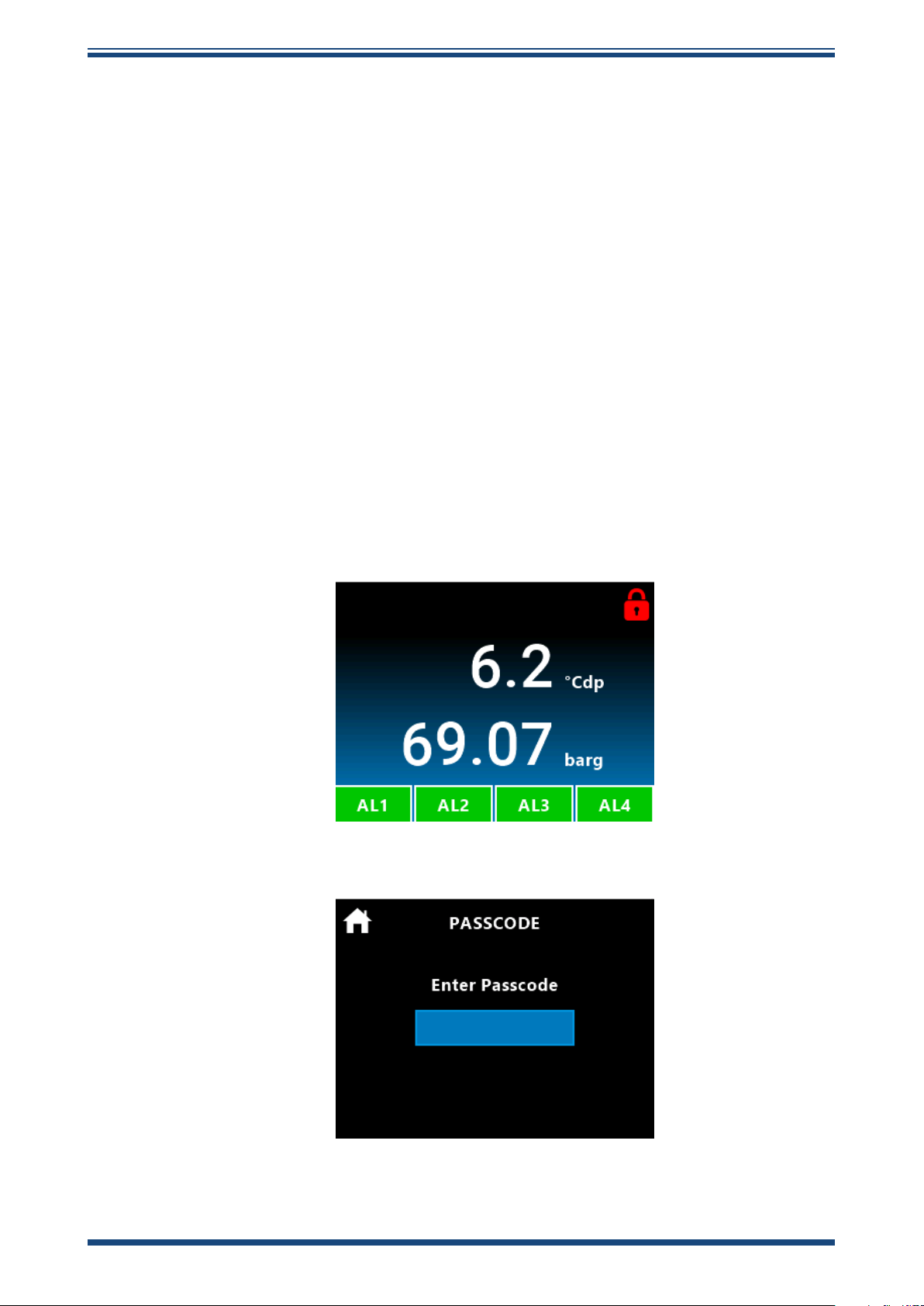
1. Press the red Lock icon on the top right-hand side of the display,
to access the security code entry screen.
2. The security code entry screen will appear.
18 97621 Issue 1.4, January 2025
Page 27
Easidew Advanced Online Hygrometer Manual
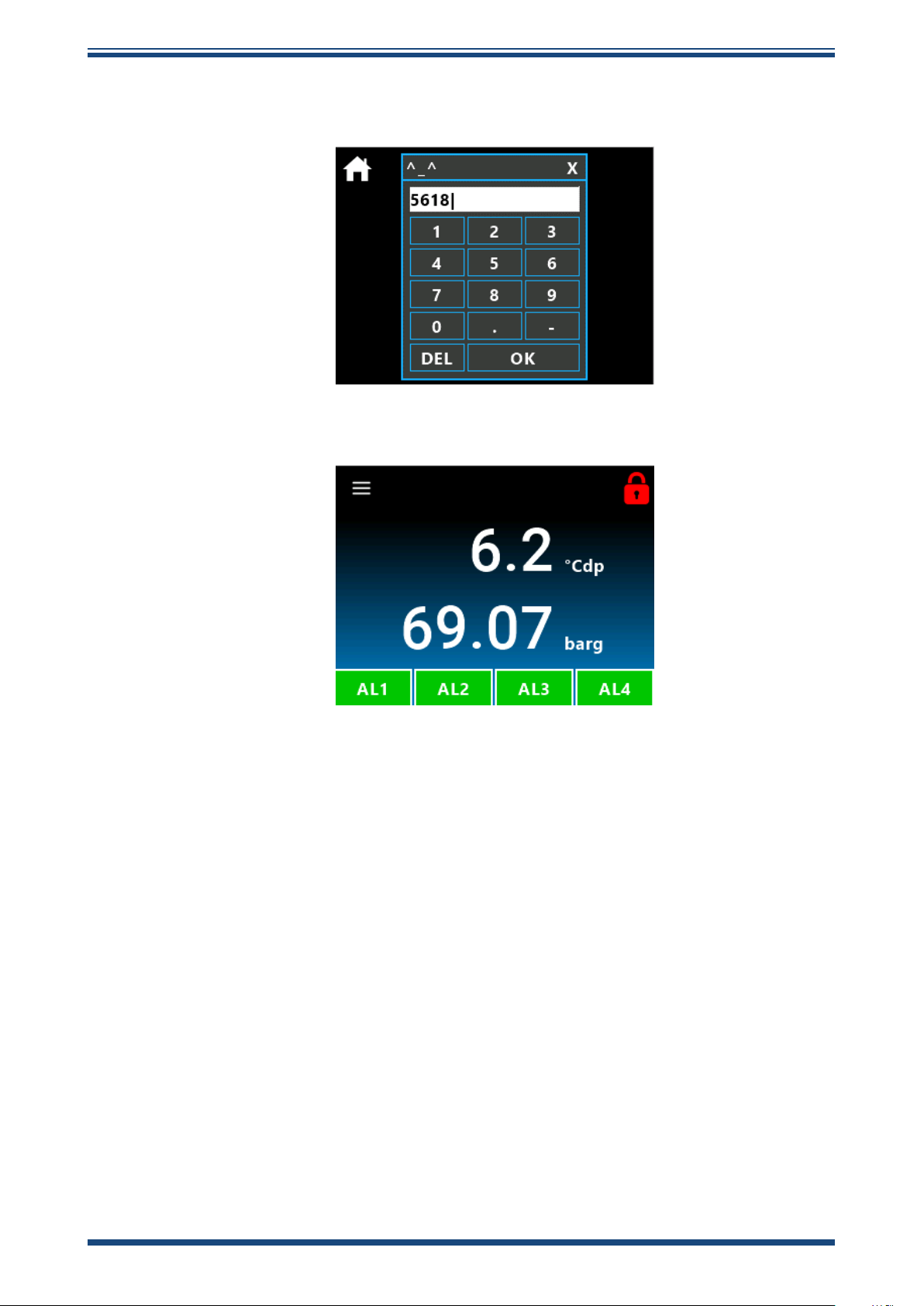
3. Enter the xed security code 5618 to access the conguration
menu.
4. Click on the Menu icon on the top left-hand side of the display.
OPERATION
Michell Instruments 19
Page 28
OPERATION
Easidew Advanced Online Hygrometer Manual
3.3 Conguration Menu Explained
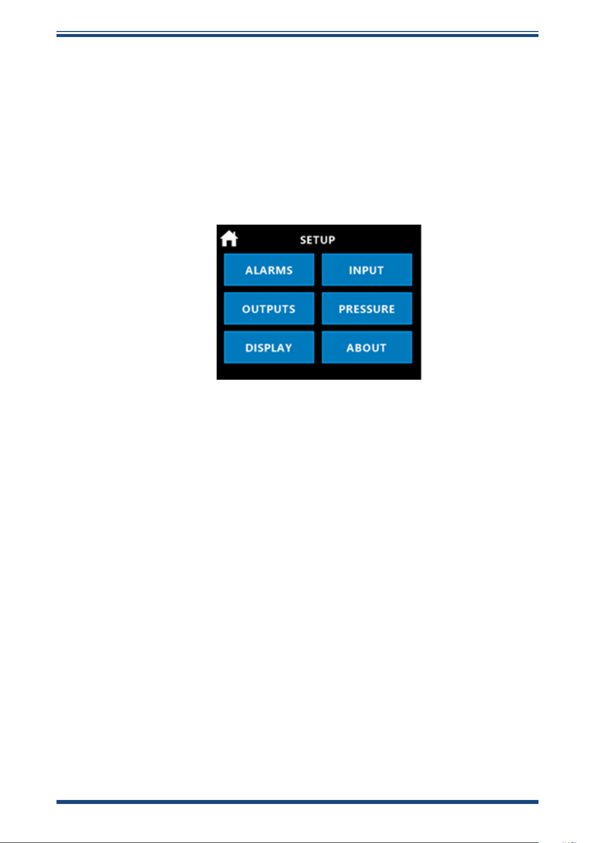
Clicking on the Menu icon will give you access to the Process Monitor conguration
menu. For most customers, you will only have to set this up once and your conguration
will be saved and will not then need to be recongured.
WARNING: If the output signals from the Process Monitor are used within
your own control system, you need to ensure good instrumentation practice
is followed and no unauthorized reconguration is undertaken which could
impact your own control system operation.
The Conguration Menu screen will appear:
Alarms There are 4 programmable alarm outputs, which can be assigned to dew point,
moisture content and pressure parameters.
Outputs There are 3 programmable 4...20 mA analog outputs, which can be assigned
to dew point, moisture content and pressure parameters.
Display Access to selection of temperature scales, Modbus address setting, pressure
scales, moisture content tables, display and brightness is via this menu.
Input On the Easidew Advanced Online Process Monitor, this menu is xed and no
variables can be entered.
Pressure Access to selection of a live pressure sensor or a xed pressure value can
be entered.
About Conrms the installed Process Monitor Firmware and Monitor product type.
20 97621 Issue 1.4, January 2025
Page 29
Easidew Advanced Online Hygrometer Manual
1
3.4 Setting Up the Process Monitor Conguration
This section looks at each menu conguration and explains, simply, how to set them up.
Please note, if there are multiple identical set-ups within one menu (e.g. 4 programmable
relay outputs), these are explained using one example.
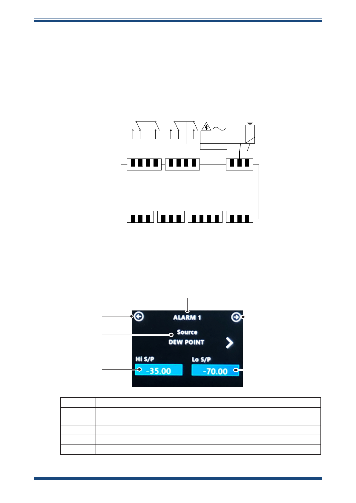
3.4.1 Alarms Conguration
The Process Monitor incorporates dual relays, each with 2 outputs, providing 4 alarm
outputs. In
Figure 17
, the relay outputs conrm this arrangement.
OPERATION
85-265 VAC
18-30 VDC
7.8 VA Max
AL1 NO
AL1 NC
COM
0V
AL2 NO
OUT 1
0V
OUT 2
AL3 NO
AL3 NC
COM
AL4 NO
24 23 22 21 20 19 18 17 16 15 14
Dew-Point RS485Analog Out
1
23 456 78910 111213
+24V
Signal / A
Figure 10
Pressure /
Temperature
B
+24V
Signal
Electrical Wiring Schematic
16 15
+V
OUT 3
14
LNE
0V
PowerAlarms 3/4 Alarms 1/2
A
B
0V
Clicking on the Alarms button will take you to the screen shown below in
Figure 18
.
5
5
2
3
1 Conrms which alarm output is being set
4
2 Selects the parameter signal for control of the relay output: dew point,
moisture, pressure, fault condition
3 Sets the energizing changeover point of the relay
4 Sets the de-energizing changeover point of the relay
5 Toggles forward or back in the menu structure
Figure 11
Alarm Conguration Screen Explained
Michell Instruments 21
Page 30
OPERATION
Each set point (e.g. Hi S/P or Lo S/P) has a built-in xed % hysteresis value to create
a small dead band below the set-point value, to ensure the relay does not constantly
energize and de-energize when the measured or calculated value oscillates around the
set-point value. This is standard practice when using relays in control systems.
The hysteresis dead-band calculation is 0.5 % of the set-point value, as shown in the
below example:
An alarm is ON when the measured value is > Hi_alarm_setpoint or the measured
value is < Lo_alarm_set point.
An Alarm is OFF when the measured value is > Lo_alarm_setpoint + Lo Hysteresis
AND the measured value is < Hi_alarm_setpoint – Hi Hysteresis.
Say, for example, Lo_alarm_setpoint is 1.0 and Hi_alarm_setpoint is 15.0.
Lo Hysteresis value = Lo_alarm_setpoint * (0.5/100.0) = 1 * 0.005 = 0.005
Hi Hysteresis value = Hi_alarm_setpoint * (0.5/100.0) = 15 * 0.005 = 0.075
Easidew Advanced Online Hygrometer Manual
The alarm will trigger when measured value reaches or exceeds 15.0 or when the
measured value is less than 1.0.
The alarm will switch o when the measured value is > 1.0 + 0.005 AND measured
value ia < 15.0 – 0.075, so as you decrease the input below 15.0, the alarm will switch
o again around 14.925.
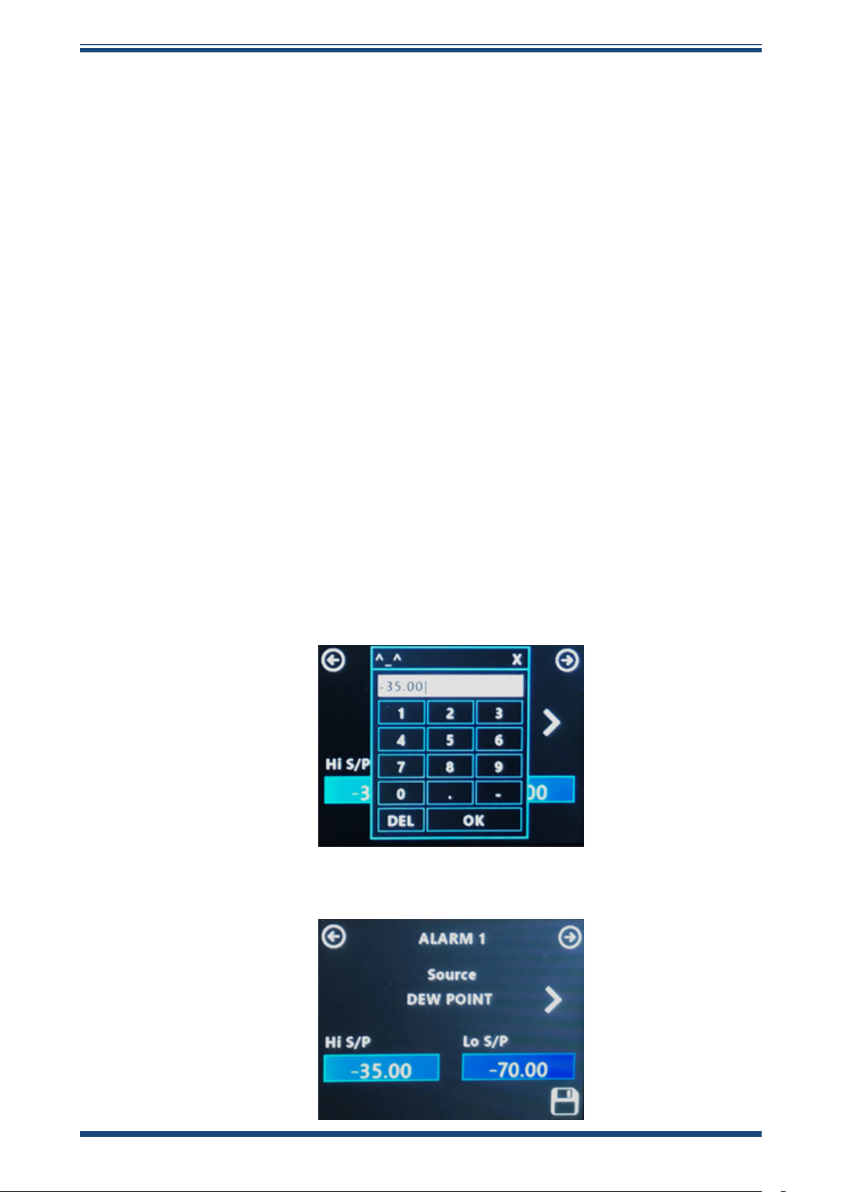
1. Click on Hi S/P, then enter your required relay switch set point and
press OK.
2. Click on the Save icon and the programmed value will be stored.
22 97621 Issue 1.4, January 2025
Page 31
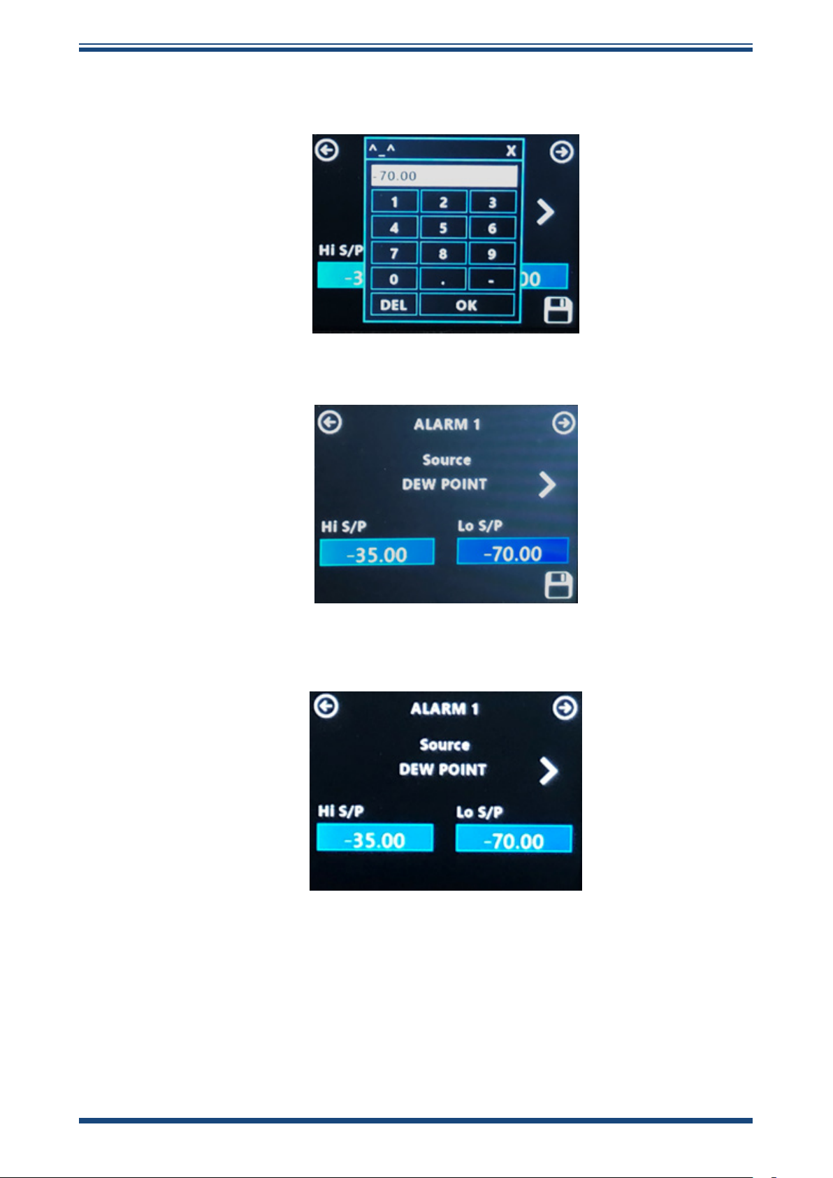
Easidew Advanced Online Hygrometer Manual
3. Click on Lo S/P, then enter your required relay switch set point and
press OK.
4. Click on the Save icon and the programmed value will be stored.
OPERATION
5. You are now back on the Alarm 1 screen, which conrms your
entered conguration.
Using the top right-hand scroll button, you can now set up the other three alarm outputs
to any required conguration, using the method described above.
Michell Instruments 23
Page 32
OPERATION
3.4.2 Analog Outputs Conguration
There are three analog 4...20 mA outputs that can be congured to any measured or
calculated parameter within the Process Monitor.
Easidew Advanced Online Hygrometer Manual
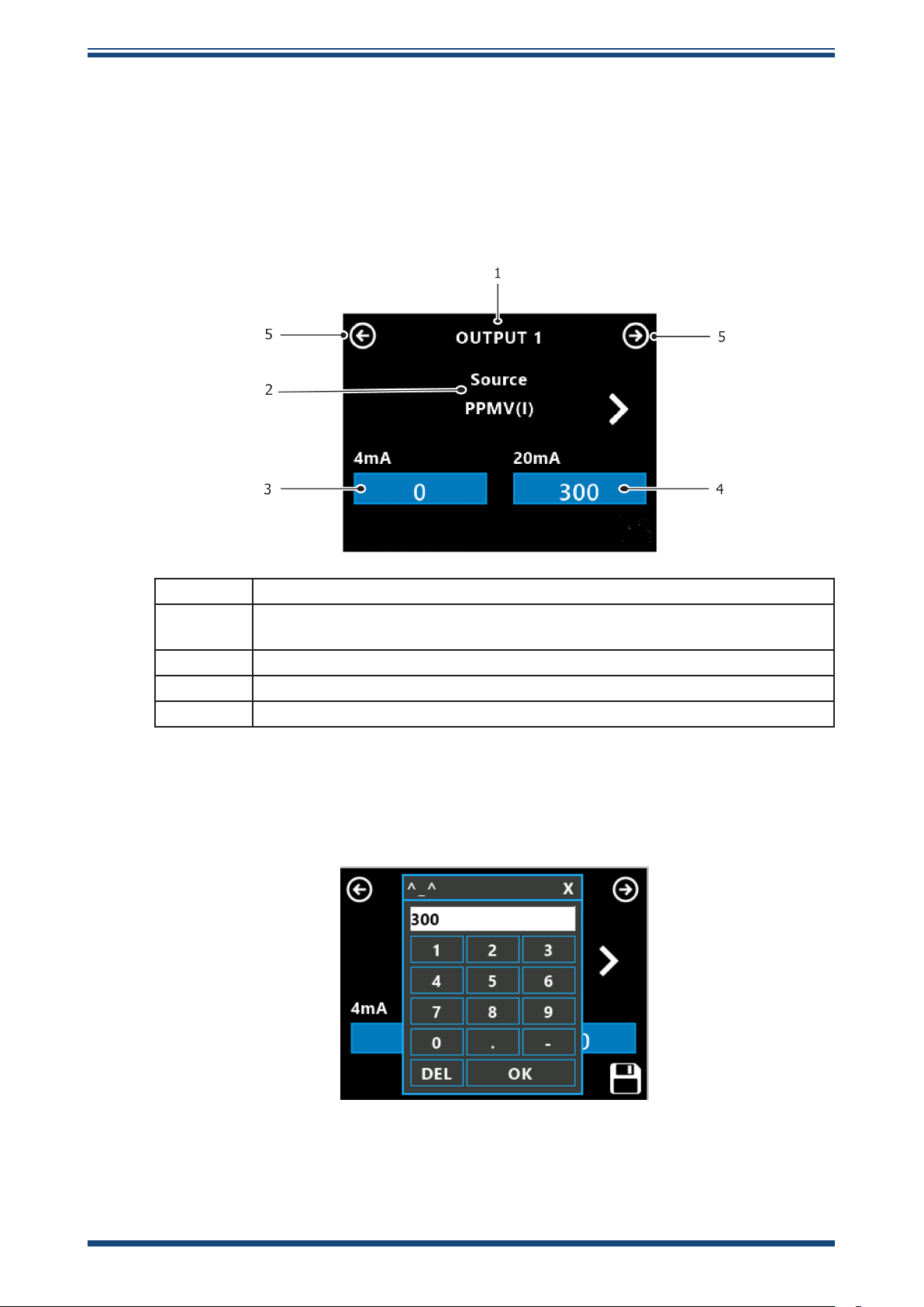
Selecting the Outputs button will take you to the screen shown below in
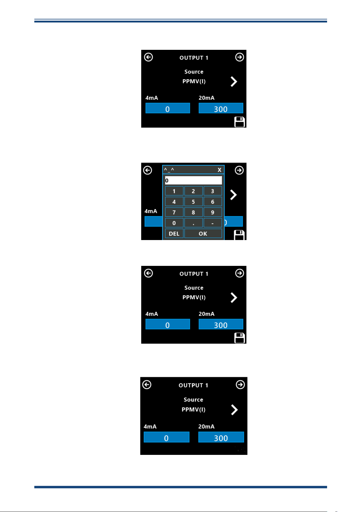
The following explains how to set up Analog Output Channel 1.
1 Conrms which 4...20 mA output is being set
2 Selects the parameter signal for analog outputting:
dew point, moisture, pressure
3 Sets the 20 mA full-scale parameter value
4 Sets the 4 mA zero parameter value
5 Toggles forward or back in the menu structure
Figure 19
.
Figure 12
1. Click on the 20 mA box and the Enter box will appear. Enter your
required full scale value, then press OK.
Analog Outputs Conguration Screen Explained
24 97621 Issue 1.4, January 2025
Page 33
Easidew Advanced Online Hygrometer Manual
2. Click on the Save icon and the programmed value will be stored.
3. Click on the 4 mA box and the Enter box will appear. Enter your
required zero value, then press OK.
OPERATION
4. Click on the Save icon and the programmed value will be stored.
5. You are now back on the Output 1 screen, which conrms your
entered conguration.
Using the top right-hand scroll button, you can now set up the other two analog outputs
to any required conguration, using the method described above.
Michell Instruments 25
Page 34
OPERATION
2
3.4.3 Display Conguration
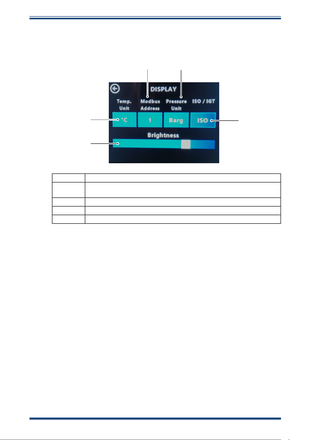
This is a simple menu screen that allows you to congure basic monitor settings and
scalings as shown in
Figure 20
Easidew Advanced Online Hygrometer Manual
below.
3
1
4
5
1 Selects the required temperature scale for the dew-point parameter
2 Sets the Modbus address for the Process Monitor RS485 digital
communications
3 Selects the required pressure scale for the indicated pressure parameter
4 Selects the required moisture content calculation table
5 Adjusts the brightness of the Process Monitor display
Figure 13
Display Conguration Screen Explained
26 97621 Issue 1.4, January 2025
Page 35
Easidew Advanced Online Hygrometer Manual
3.4.4 Input Conguration
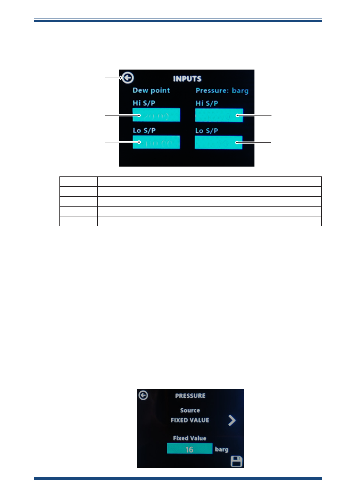
This is a simple menu screen displaying the measured or xed inputs to the Process
Monitor, as shown below in
Figure 21
.
5
OPERATION
1
2
1 Displays the highest measurement value of the dew-point sensor input
2 Displays the lowest measurement range of the dew-point sensor input
3 Displays the highest indicated or xed input of pressure
4 Displays the lowest indicated or xed input of pressure
5 Toggles back in the menu structure
Figure 14
Dew point and pressure are the two parameters inputted in the Process Monitor within the
hygrometer system. These are displayed on this screen in dierent forms, as explained:
Dew Point The Easidew M12 Dew-Point Sensor outputs a Modbus RTU over RS485
signal into the Process Monitor and that sensor, irrespective of its ordered dew-point
range, is digitally scaled to measure any dew point within the band of -110...+20 °C dp.
The Hi S/P and Lo S/P boxes are greyed out; they conrm this -110...+20 °C range and
this cannot be adjusted.
Input Conguration Screen Explained
3
4
Pressure Section 3.4.5, Pressure Conguration, explains that pressure indication can
be inputted into the Process Monitor either with a live pressure signal from an external
4...20 mA pressure sensor or through a xed pressure value entry on the Process Monitor.
Dependent on this selection, the Input Conguration screen changes mode, as follows:
1. When a xed pressure entry value is selected in the Pressure
Conguration screen, the value is entered and saved.
Michell Instruments 27
Page 36
OPERATION
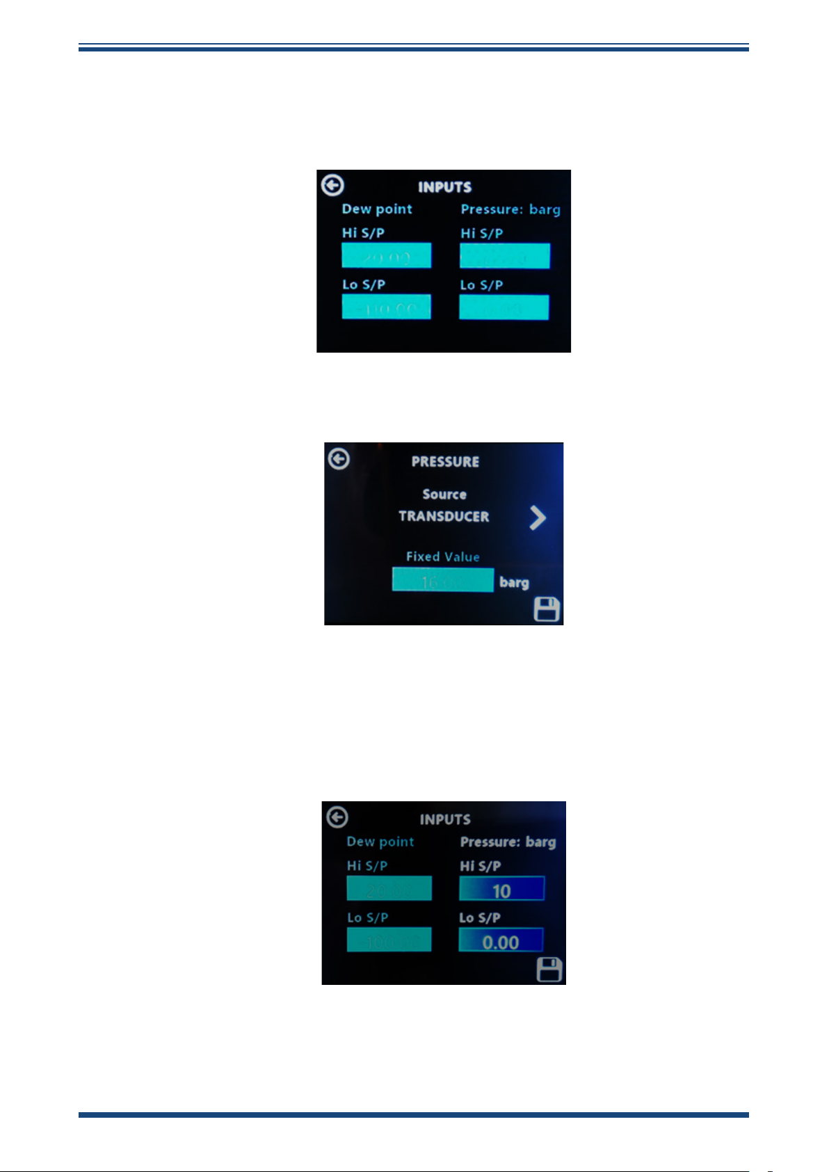
2. If you go back to the Input Conguration screen you will see the
3. Go back to the Pressure Conguration screen and select
Easidew Advanced Online Hygrometer Manual
display below, with the Pressure Hi S/P and Lo S/P boxes greyed
out, conrming that no live pressure signal is being inputted to the
Process Monitor.
Transducer (sensor), then save your selection.
4. Go back to the Input Conguration screen and enter the Hi
S/P value equating to 20 mA, then the Lo S/P value equating to
4 mA value of the external pressure sensor. Save this input.
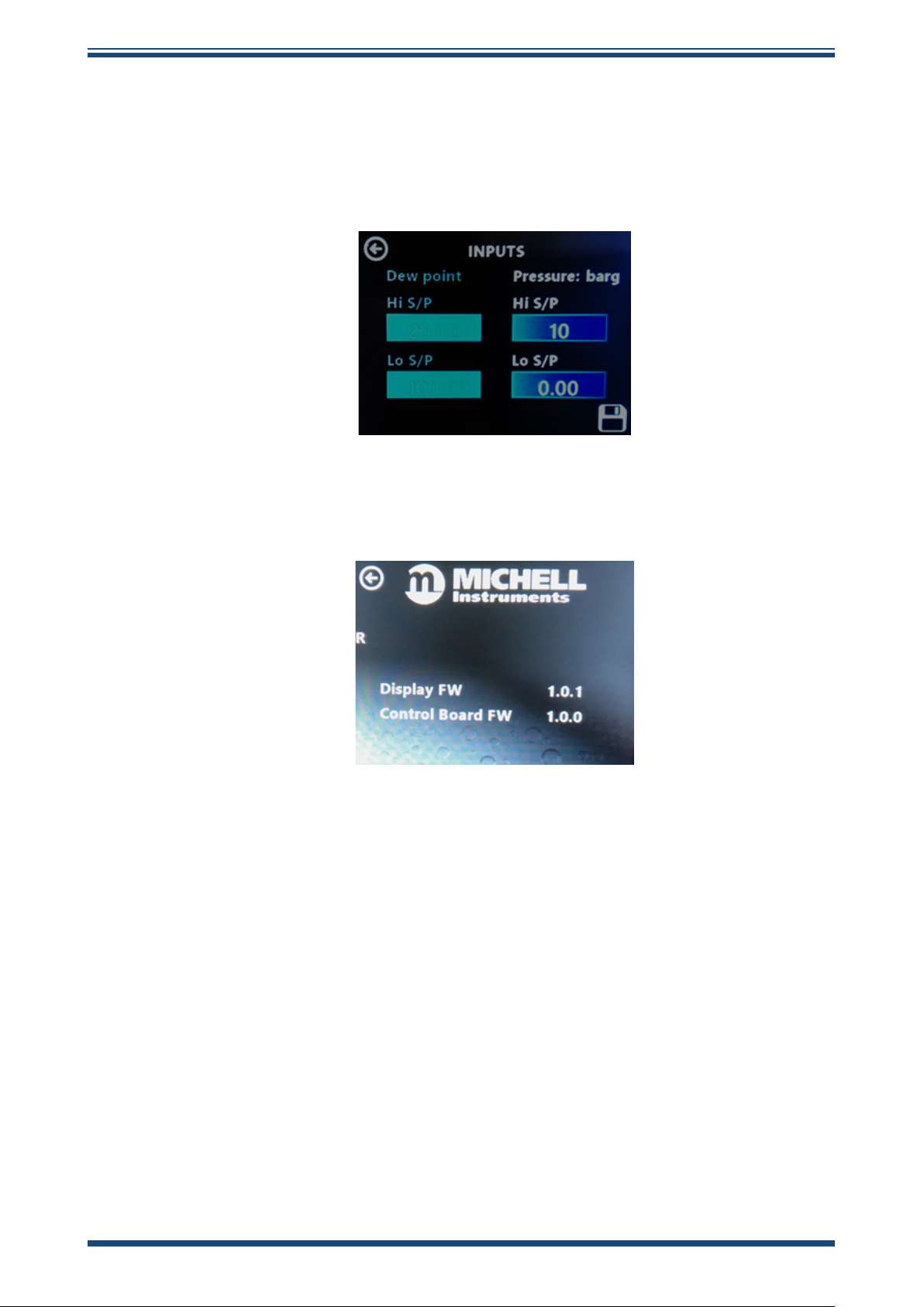
In the example below, a 0...10 bar (4...20 mA) pressure sensor is being used to input a
live pressure signal into the Process Monitor.
28 97621 Issue 1.4, January 2025
Page 37
Easidew Advanced Online Hygrometer Manual
3.4.5 Pressure Conguration
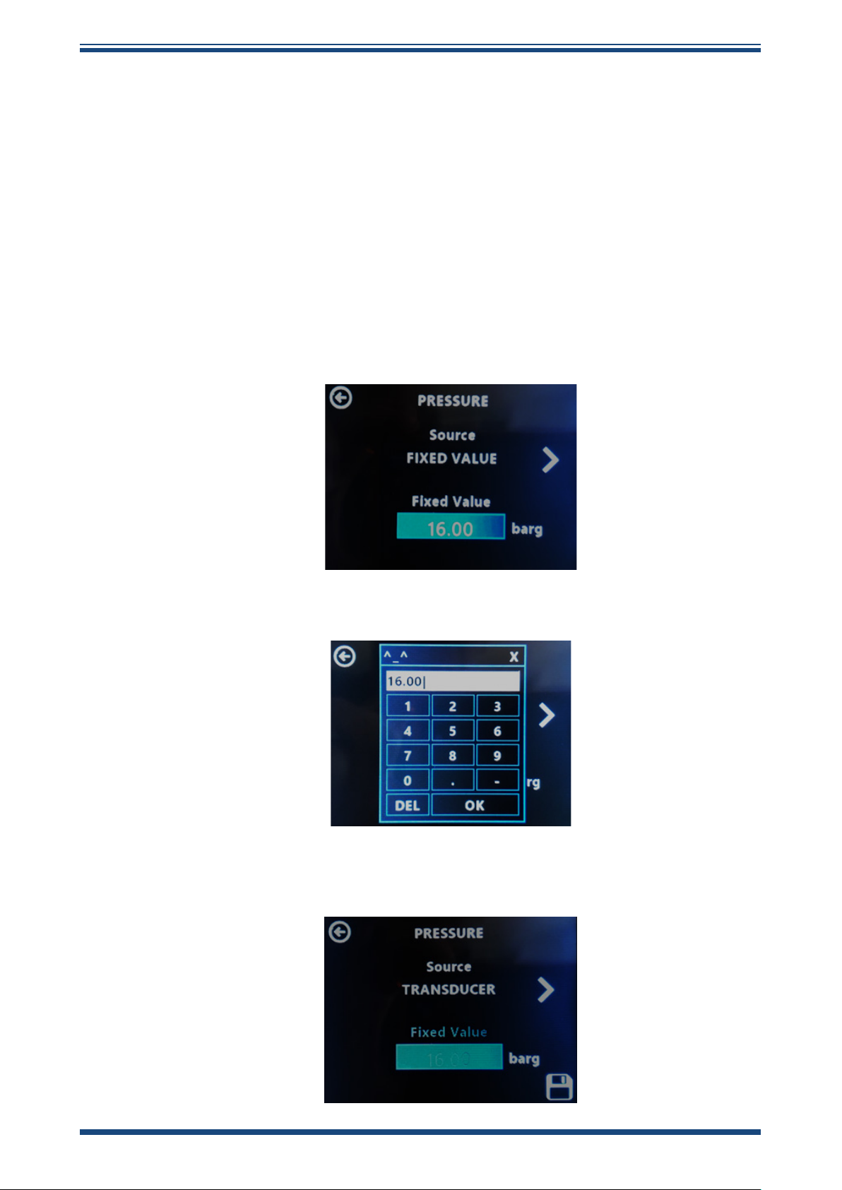
Pressure indication can be inputted into the Process Monitor either with a live pressure
signal from an external 4...20 mA pressure sensor or through a xed pressure value entry
on the Process Monitor. To calculate moisture content from dew point, it is necessary
to know the system pressure and this pressure indication input is then used for that
purpose.
NOTE: This function is only relevant to moisture content calculation and is
not applicable for dew-point measurement.
The two screens used to select live pressure input or xed value input are shown below,
along with a brief explanation of use.
1. Click on Pressure, then on the next screen select Fixed Value as
the source input for Pressure.
OPERATION
2. Enter the xed value, then save your entry.
3. Click on the ⇦ arrow, then select Transducer (sensor) as the source
input.
Michell Instruments 29
Page 38
OPERATION
4. Go back to the Input Conguration screen, then enter the Hi S/P
In the example below, a 0...10 bar (4...20 mA) pressure sensor is being used to input a
live pressure signal into the Process Monitor.
Easidew Advanced Online Hygrometer Manual
value equating to 20 mA and the Lo S/P value equating to 4 mA
value of the external pressure sensor. Save this input.
3.4.6 About Menu
This is an information screen that conrms the product name, main PCB rmware and
display rmware.
30 97621 Issue 1.4, January 2025
Page 39

Easidew Advanced Online Hygrometer Manual
4 MAINTENANCE
4.1 Maintenance and Calibration
Routine maintenance of the Easidew M12 Transmitter is conned to regular re-calibration.
For most applications, annual re-calibration ensures that the stated accuracy of the
Easidew M12 Transmitter is maintained.
Specialist calibration instrumentation is required to calibrate the transmitter and a true
calibration can only be performed by exposure of the dew-point sensor to a reference
gas of known dew point.
Calibration services are oered by Michell Instruments at their accredited calibration
laboratories. All calibrations are traceable to national standards either via the National
Physical Laboratory (UK) or the National Institute of Standards and Technology (USA).
The Easidew M12 transmitter can be returned to Michell Instruments either directly or
via the authorized distributor, for calibration.
MAINTENANCE
Alternatively, Michell Instruments can provide an exchange transmitter. Prior to recalibration, an exchange transmitter can be ordered from Michell Instruments or an
authorized distributor.
Once the replacement transmitter and calibration certicate have been received, the
original transmitter can be disconnected and the replacement transmitter tted in its
place. The original transmitter should be packed in its original packing, if possible, and
returned to Michell Instruments, either directly or via an authorized agent.
4.2 Fault Conditions
There are 2 conditions stated below, which will cause a FAULT message to be displayed
for the dew-point or moisture content parameter on the display.
• The sensor cable connecting the Easidew M12 sensor to the Process
Monitor is disconnected or damaged.
• The Easidew M12 sensor ags a fault condition from the measurement
technology to the sensor registers, which is then transmitted to the
Process Monitor.
If the FAU LT message is displayed, it is recommended that the electrical wiring system
between the Easidew M12 sensor and Process Monitor is checked for connectivity.
Michell Instruments 31
Page 40

MEASUREMENT GUIDE
Easidew Advanced Online Hygrometer Manual
5 MEASUREMENT GUIDE
5.1 Sampling Considerations
There are two basic methods of measuring a sample with the Easidew M12 Transmitter:
• In-situ measurements are made by placing the transmitter inside the
environment to be measured.
• Extractive measurements are made by installing the sensor into a block
within a sample handling system, and owing the sample outside of the
environment to be measured through this system.
Extractive measurements are recommended when the conditions in the environment
to be measured are not conducive to making reliable measurements with the product.
Examples of such conditional limitations are:
• Excessive ow rate
• Presence of particulates matter
• Presence of entrained liquids
• Excessive sample temperature
The basic considerations for each measurement type are as follows:
32 97621 Issue 1.4, January 2025
Page 41
Easidew Advanced Online Hygrometer Manual
In-Situ
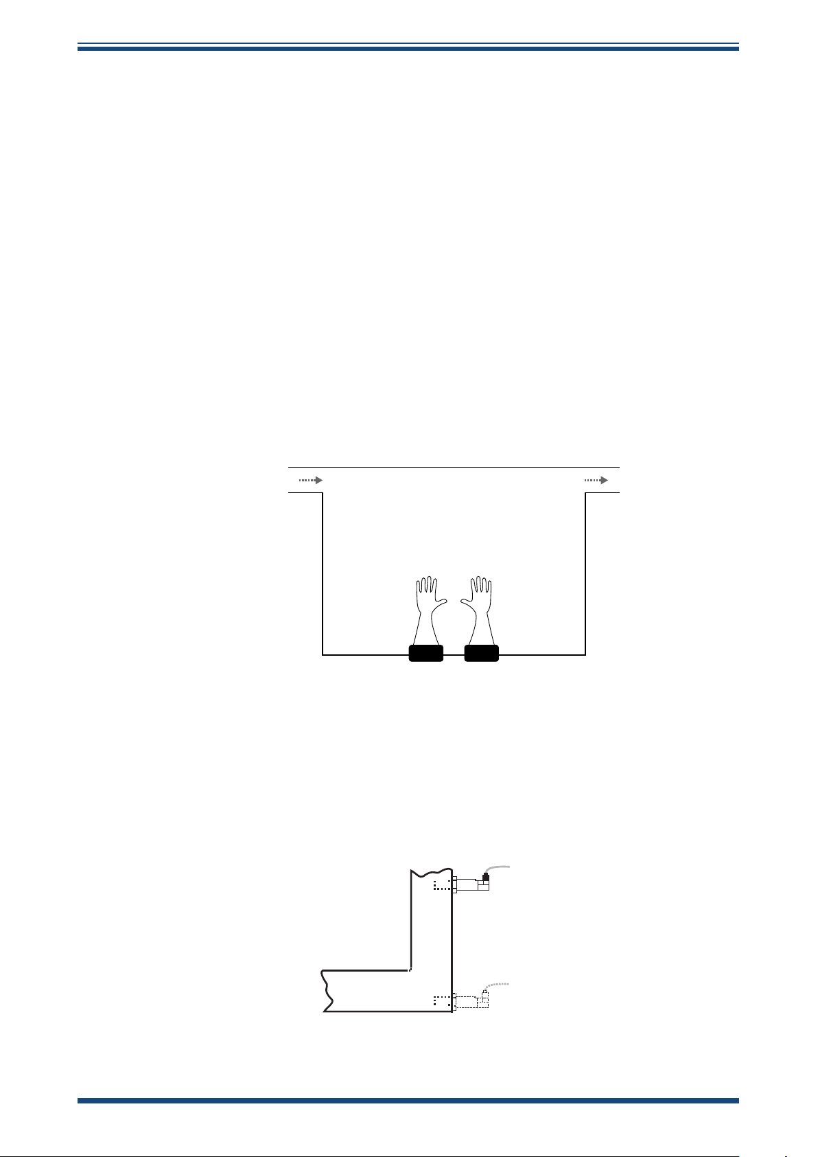
1. Dew-Point Sensor Position – will the sensor see an area of the
environment that is representative of what you want to measure?
For example, if the sensor is to be mounted into a glove box, there are three dierent
positions in which it could be installed – each giving a dierent measurement:
• Position A is on the purge inlet. In this position the sensor will conrm the
dew point of the gas entering the glove box, but will not detect any leaks
in the glove box itself, or any moisture released from the work piece.
• Position B is on the gas outlet. In this position the sensor will be exposed
to the gas leaving the glove box, and will therefore be detecting any
moisture which has entered into the system (e.g. ingress/leaks), or has
been released by the work piece.
• Position C is in the glovebox itself, in this position the sensor will be
only detecting any moisture in its immediate vicinity. Leaks not in close
proximity to the measurement point may not be detected as this moisture
could be drawn directly to the outlet.
MEASUREMENT GUIDE
A
1 2
B
C
1. Purge Inlet
2. Gas Outlet
Figure 15
If the transmitter is to be mounted directly into a pipe or duct, then consider that the
installation point should not be too close to the bottom of a bend where oil or other
condensate may collect.
Installation Location
Figure 16
Michell Instruments 33
Installation Location
Page 42

MEASUREMENT GUIDE
2. Gas speed – if you are planning on installing the sensor in a duct, consider
how fast the sample gas is moving through it.
If the gas speed is very low, or occasionally static, then the moisture content through
the length (and width, if it is more than a few cm across) of the duct is unlikely to be
uniform.
Extremely high gas speeds can cause damage to the sensor. Direct insertion is not
recommended in gas speeds in excess of 10m/s (32.8ft/s).
3. Particulates – Particulates travelling at speed can cause severe and
irreversible damage to the sensor. At low velocity they can cling to the sensor,
reducing its’ surface area, and therefore response speed.
The sensor is provided with a basic level of particulate protection in the form of
a sintered guard; either HMWPE (10μm pore size) or Stainless Steel (80μm pore
size). If the sample stream contains smaller particulates than this, or generally large
amounts of dust; extractive measurement is recommended to accommodate proper
in-line ltration.
Easidew Advanced Online Hygrometer Manual
4. Sample Temperature – Although the Easidew M12 can be operated
at sample temperatures up to 60 °C, it is advisable to keep the sample
temperature as close to ambient, and as stable as possible to keep adsorption
& desorption characteristics as consistent as possible (see Section 5.2,
Sampling Hints, for more information).
Extractive
If the sensor is to be mounted into a sample conditioning system, then the above points are
still of relevance, but it is important to consider the extraction point itself – make sure that
the chosen extraction point is representative of the process, i.e. that the sample of interest
is owing past the extraction point, and it is not being pulled from a dead volume.
34 97621 Issue 1.4, January 2025
Page 43
Easidew Advanced Online Hygrometer Manual
5.2 Sampling Hints
Measurement of moisture content is a complex subject, but does not need to be dicult.
This section aims to explain the common mistakes made in measurement situations, the
causes of the problem, and how to avoid them. Mistakes and bad practices can cause the
measurement to vary from the expectation; therefore a good sampling technique is crucial
for accurate and reliable results.
MEASUREMENT GUIDE
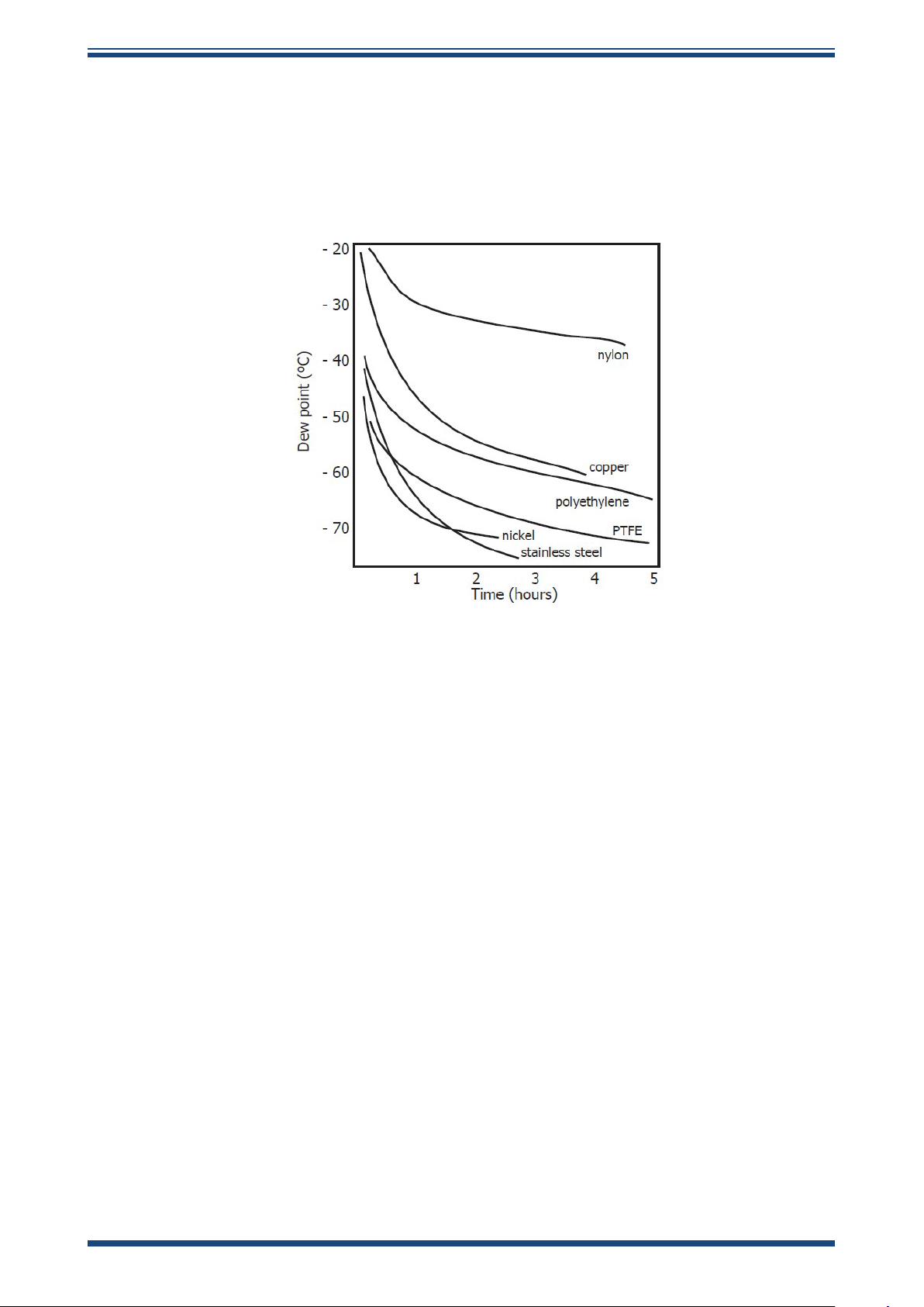
Figure 17
All materials are permeable to water vapor, as the water molecule is extremely small cored
to the structure of solids, even when compared to the crystalline structure of metals. The
graph above shows the dew point inside tubing of dierent materials when purged with
very dry gas, where the exterior of the tubing is in the ambient environment.
Many materials contain moisture as part of their structure, particularly organic materials
(natural or synthetic), salts (or anything which contains them) and anything which
has small pores. It is important to ensure that the materials used are suitable for the
application.
If the partial water vapor pressure exerted on the outside of a compressed air line is
higher than on the inside, the atmospheric water vapor will naturally push through the
porous medium causing water to migrate into the pressurised air line. This eect is called
transpiration.
Adsorption and Desorption
Adsorption is the adhesion of atoms, ions, or molecules from a gas, liquid, or dissolved
solid to the surface of a material, creating a lm. The rate of adsorption is increased at
higher pressures and lower temperatures.
Material Permeability Comparison
Desorption is the release of a substance from or through the surface of a material.
In constant environmental conditions, an adsorbed substance will remain on a surface
almost indenitely. However, as the temperature rises, so does the likelihood of desorption
occurring.
Michell Instruments 35
Page 44
MEASUREMENT GUIDE
In practical terms, as the temperature of the environment uctuates, water molecules are
adsorbed and desorbed from the internal surfaces of the sample tubing, causing small
uctuations in the measured dew point.
Sample Tubing Length
The sample point should always be as close to the critical measurement point as possible,
in order to obtain a truly representative measurement. The length of the sample line
to the sensor or instrument should be as short as possible. Interconnection points and
valves trap moisture, so using the simplest sampling arrangement possible will reduce the
time it takes for the sample system to dry out when purged with dry gas.
Over a long tubing run, water will inevitably migrate into any line, and the effects
of adsorption and desorption will become more apparent. It is clear from the graph
shown above that the best materials to resist transpiration are stainless steel and
PTFE.
Trapped Moisture
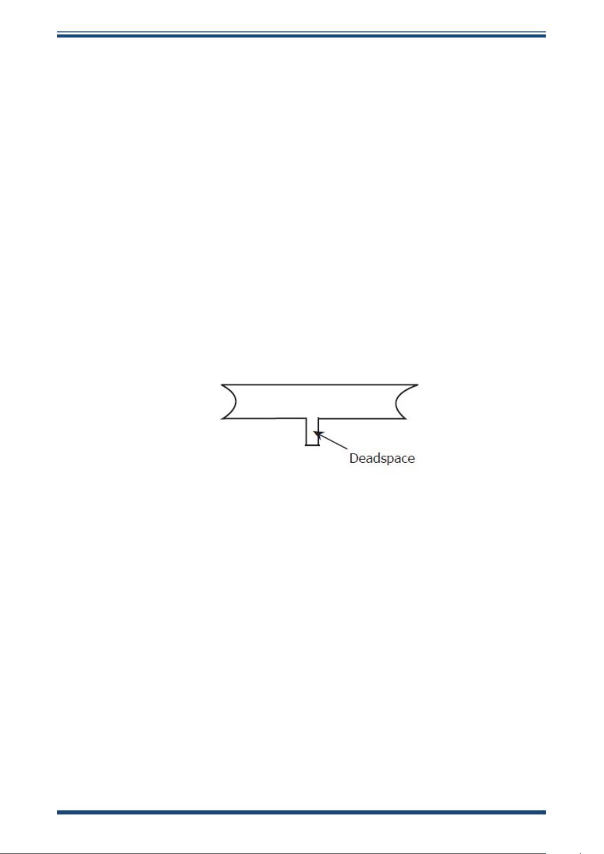
Dead volumes (areas which are not in a direct flow path) in sample lines, hold
onto water molecules which are slowly released into the passing gas; this results in
increased purge and response times, and wetter than expected readings. Hygroscopic
materials in filters, valves (e.g. rubber from pressure regulators) or any other parts of
the system can also trap moisture.
Easidew Advanced Online Hygrometer Manual
Figure 18
Sample Conditioning
Sample conditioning is often necessary to avoid exposure of sensitive measuring
components to liquids and other contaminants which may cause damage or affect the
accuracy over time, depending on the measurement technology.
Particulate filters are used for removing dirt, rust, scale and any other solids that may
be in a sample stream. For protection against liquids, a coalescing filter should be
used.
The membrane filter is a more expensive but highly effective alternative to a coalescing
filter. It provides protection from liquid droplets, and can even stop flow to the analyser
completely when a large slug of liquid is encountered.
Condensation and Leaks
Maintaining the temperature of the sample system tubing above the dew point of the
sample is vital to prevent condensation. Any condensation invalidates the sampling
process as it changes the water vapor content of the gas being measured. Condensed
liquid can alter the humidity elsewhere by dripping or running to other locations
where it may re-evaporate.
Dead volume
36 97621 Issue 1.4, January 2025
Page 45

Easidew Advanced Online Hygrometer Manual
The integrity of all connections is also an important consideration, especially when
sampling low dew points at an elevated pressure. If a small leak occurs in a high
pressure line, gas will leak out but vortices at the leak point and a negative vapor
pressure differential will also allow water vapor to contaminate the flow.
Flow Rates
Theoretically flow rate has no direct effect on the measured moisture content, but
in practice it can have unanticipated effects on response speed and accuracy. The
optimal flow rate varies depending on the measurement technology, and can always
be found in the instrument or sensor manual.
An inadequate ow rate can:
• Accentuate adsorption and desorption eects on the gas passing through the
sampling system.
• Allow pockets of wet gas to remain undisturbed in a complex sampling
system, which will then gradually be released into the sample ow.
• Increase the chance of contamination from back diusion: ambient air that
is wetter than the sample can ow from the exhaust back into the system.
A longer exhaust (sometimes called a pigtail) can also help alleviate this
problem.
MEASUREMENT GUIDE
• Slow the response of the sensor to changes in moisture content.
Michell Instruments 37
Page 46

APPENDIX A
Easidew Advanced Online Hygrometer Manual
Appendix A
Technical Specications
38 97621 Issue 1.4, January 2025
Page 47
Easidew Advanced Online Hygrometer Manual
APPENDIX A
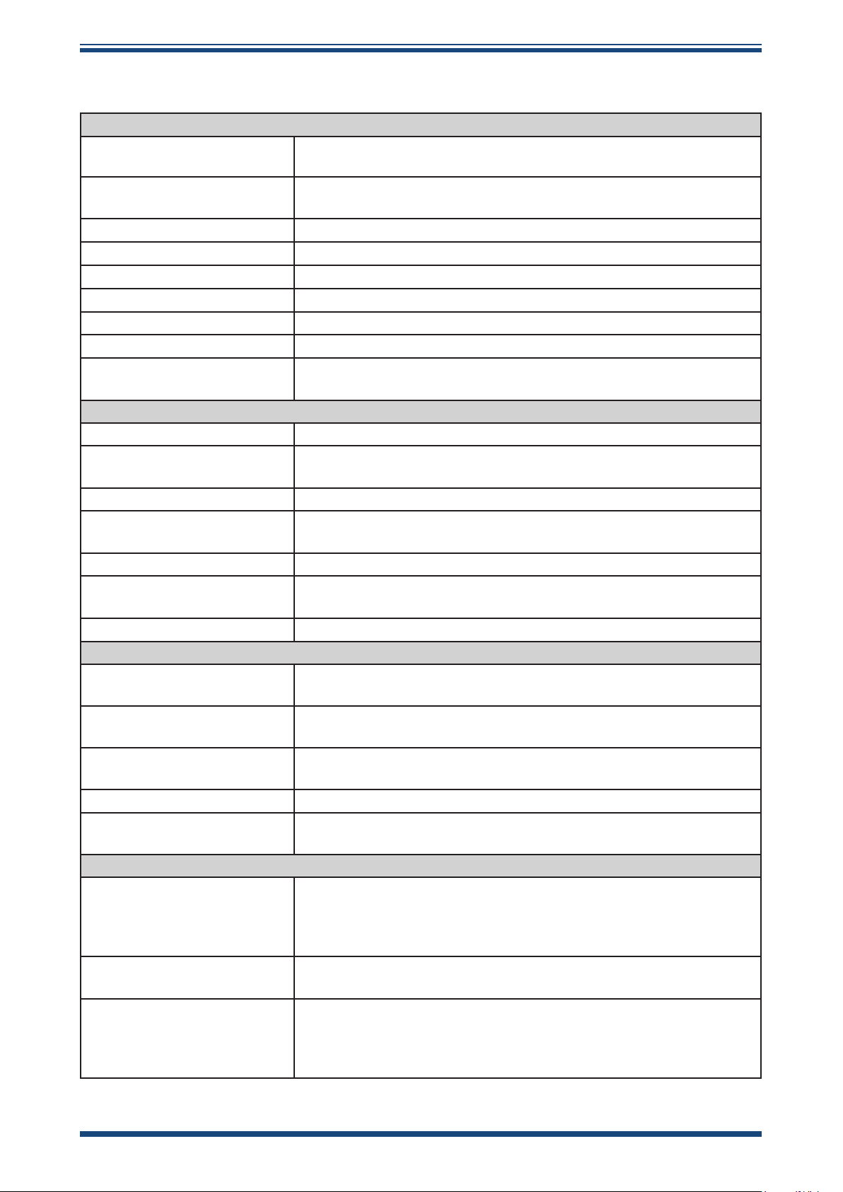
Appendix A Technical Specications
Performance Specications
Measurement Range
Accuracy *
Response Time 5 mins to T95 (dry to wet)
Repeatability 0.5 °C (0.9 °F) dew point
Sensor Calibration Traceable 13-point calibration certicate
Auxiliary Pressure Input 52.5 MPa (525 barg/7614 psig) maximum
Pressure Compensation Live 4 ...20 mA pressure transmitter or xed programmable value
Moisture Content Scales Automatic compensation for ppmV, lbs/MMscf, g/m3 units
Relay Alarm Type/Rating
Electrical Specications
Sensor Input Signal Modbus RTU over RS485
Online Output Signals
Online Outputs Dew point, Moisture Content, Pressure
Maximum Analog Output
Scaled Range
Online Supply Voltage 85...265V AC; 18...30V DC
Online Power Consumption
Electrical Safety BS/EN61010-1: 2010
Operating Specications
Operating Temperature
Compensated Temperature
Range
Storage Temperature
Operating Pressure 52.5 MPa (525 barg/7614 psig) maximum
Sensor Flow Rate
Mechanical Specications
Ingress Protection
System Materials
Dimensions
-110...+20 °C dew point (-166...+68 °F); -100...+20 °C
(-148...+68 °F) dew point
±1 °C from -60 to +20 °C dew point (±1.8 °F, -76...+68 °F dp)
±2 °C from -100 to -60 °C dew point (±3.6 °F, -148...-76 °F dp)
2 x Form A, 2 x Form C 30V DC 5A Namur compliant
programmable relay contacts for process and fault conditions
3 x 4...20 mA channels; Modbus RTU over RS485; 4 programmable
relay alarms
Dew point: -110 up to +20 °C (-166 up to +68 °F)
Moisture content in gas: 0 up to 3000 ppm
V
AC Power: 7.8 VA (2.89 W)
DC Current: 170 mA @24V DC
Sensor: -40...+60 °C (-40...+140 °F)
Process Monitor: 0...+70 °C (+32...+158 °F)
Sensor: -20 °C...+50 °C (-4 °F...+122 °F); Process Monitor: not
applicable
Sensor: -40...+60 °C (-40...+140 °F)
Process Monitor: 0...+85 °C (+32...+185 °F)
1...5 l/min mounted in standard sampling block; 0...10 m/sec direct
insertion
Sensor: IP66 in accordance with standard BS EN
60529:1992+A2:2013; NEMA 4 protection in accordance with
standard NEMA 250–2014
Process Monitor: IP54 & NEMA Type 2 & 12K front panel only
Sensor & Sample Block: 316 stainless steel
Process Monitor: UL Rated ABS - EpsotechAB AN2 V0
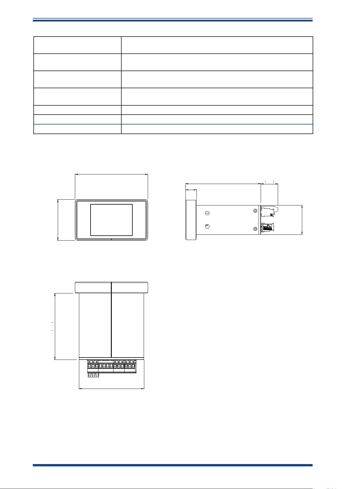
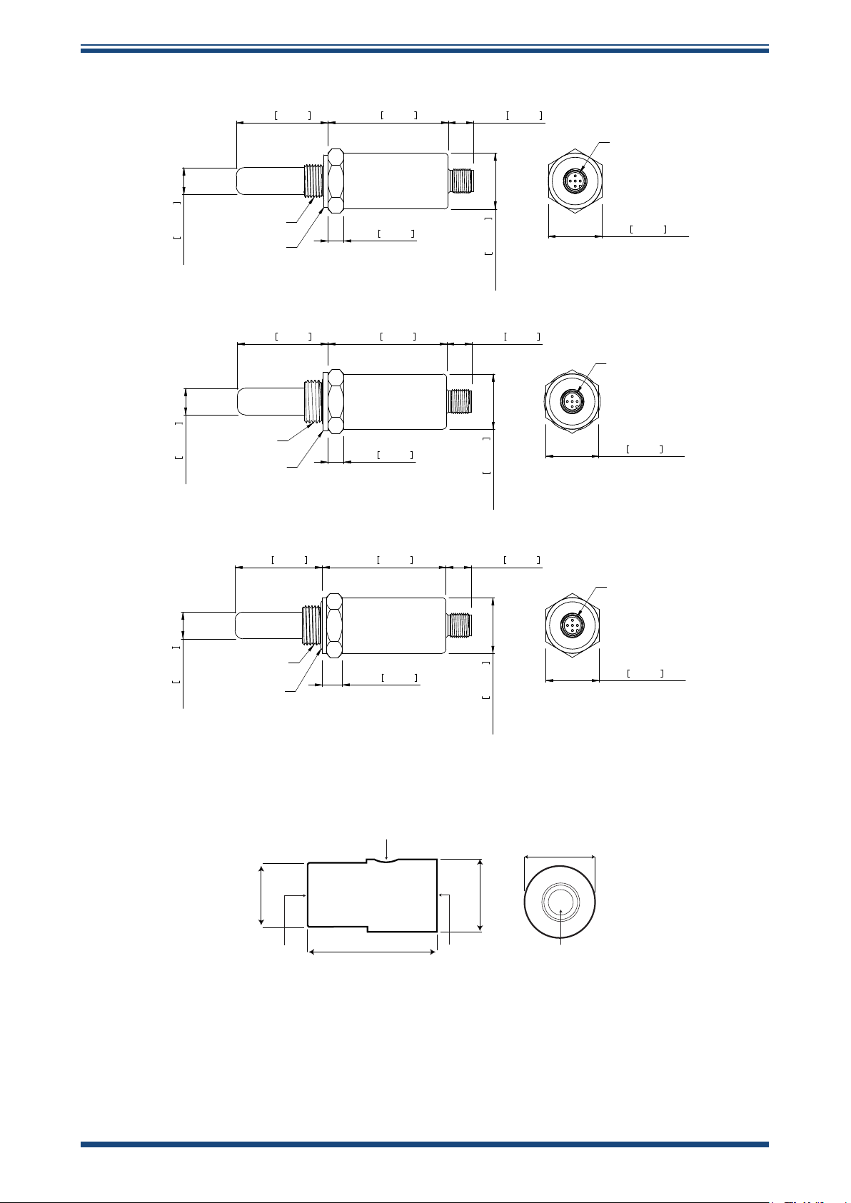
Sensor: L=119 x 27 mm / L=5.2” x ø1.77” (no connector cable)
Process Monitor: 1/8 DIN Case, 90 x 40 x 92 mm / 3.54 x 1.57 x
3.62” (w x h x d)
Sample Block: 55.2 x 30 mm / 2.17 x 1.18”
Michell Instruments 39
Page 48
APPENDIX A
15.6
107.7
24.4
42.0
Easidew Advanced Online Hygrometer Manual
Filter (Sensor Protection)
Sensor/Sample Block Process
Connections
Sample Block Inlet/Outlet
Connections
System Weights
Standard: HDPE <10μm
Optional: 316 stainless steel sintered guard <80μm
G1/2” BSP, 3/4” 16 UNF, 5/8” 18 UNF
1/8” NPT
Sensor 150 g (5.29 oz); Sample Block 250 g (8.82 oz);
Process Monitor 280 g (9.88 oz)
Sensor Electrical Connections Easidew M12: M12 5 pin (A Coded)
Online Sensor Cable 2, 5, 10 meter (6.5, 16.4, 32.81 ft) connector/cable available
Display Type LCD touch screen 320 x 240 pixel
NOTES * Over Compensated Temperature Range
100.8
107.7
15.6
24.4
56.8
92.1
90.0
42.0
Easidew Online Process Monitor
40 97621 Issue 1.4, January 2025
Page 49
Easidew Advanced Online Hygrometer Manual
13.0 0.512
46.0 1.811
60.3 2.374
12.7 0.500
8.0 0.315
27.0 1.063
O
5/8" UNF THREAD
BONDED SEAL
M12 5-WAY
A CODED
27.0 1.063 A/F
DIMENSIONS IN mm [INCHES]
13.0 0.512
46.0 1.811 60.3 2.374 12.7 0.500
8.0 0.315
27.0 1.063
O
G1/2 THREAD
BONDED SEAL
M12 5-WAY
A CODED
27.0 1.063 A/F
DIMENSIONS IN mm [INCHES]
13.0 0.512
44.0 1.732 62.3 2.453 12.7 0.500
10.0 0.394
27.0 1.063
O
3/4" UNF THREAD
O-RING SEAL
M12 5-WAY
A CODED
27.0 1.063 A/F
DIMENSIONS IN mm [INCHES]
ø30mm
55.2mm
27 A/F
30mm
5/8”-18 UNF
3/4” UNF
G1/2” BSP
1/8” NPT
5/8”-18 UNF
3/4” UNF
G1/2” BSP
1/8” NPT
APPENDIX A
M12 Sensor Cable (included)
Sample Block (included)
Michell Instruments 41
Page 50

APPENDIX B
Easidew Advanced Online Hygrometer Manual
Appendix B
Process Monitor
Register Map
42 97621 Issue 1.4, January 2025
Page 51
Easidew Advanced Online Hygrometer Manual
APPENDIX B
Appendix B Process Monitor Register Map
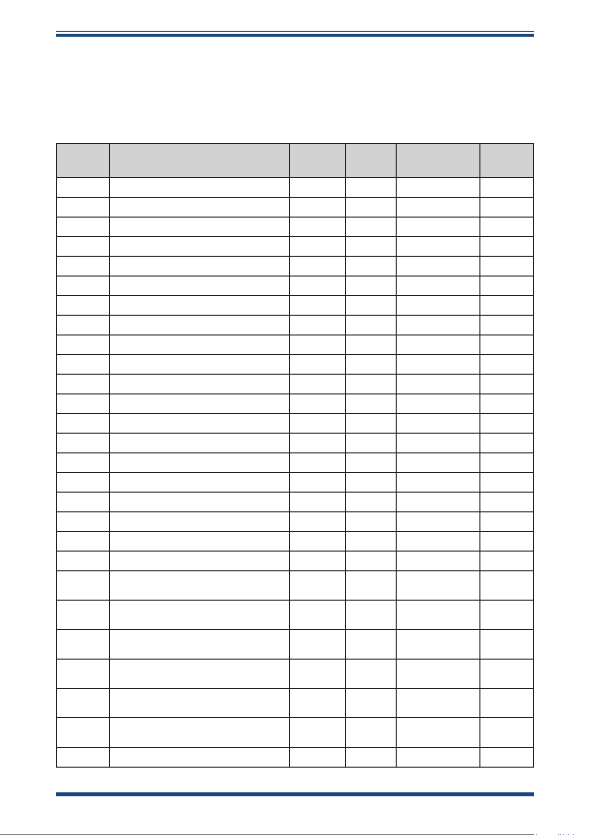
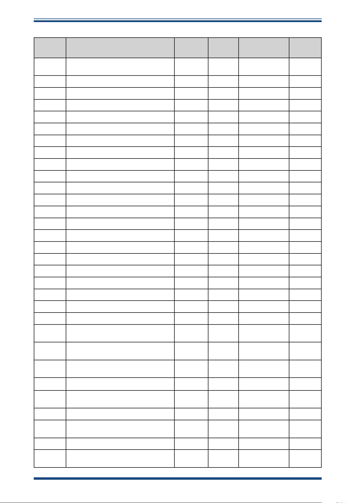
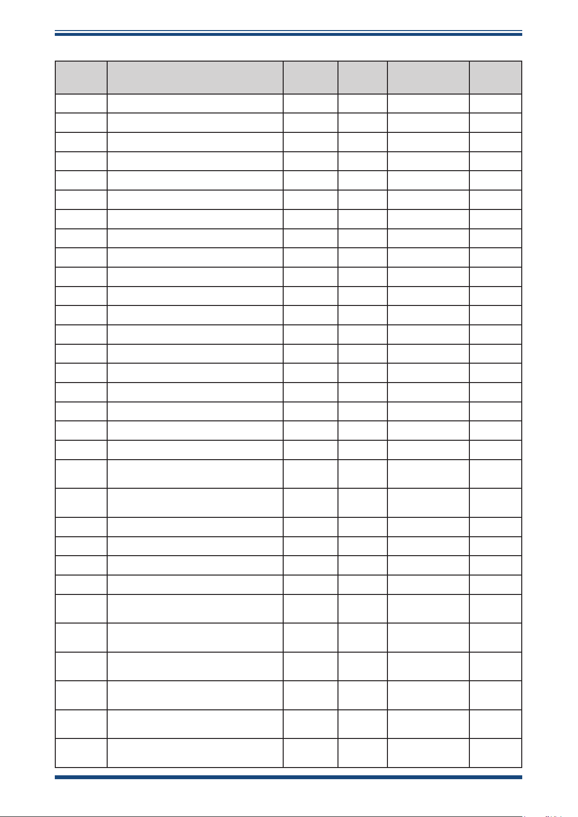
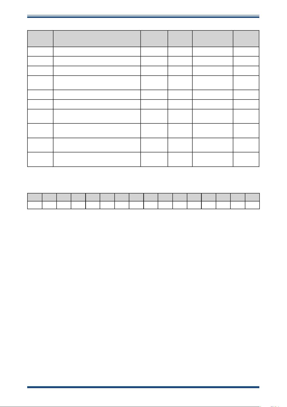
This is a register map for all rmware versions of the Process Monitor. Some registers are not
applicable to the Easidew Advanced Online Hygrometer.
Serial Port Settings: 9600 Baud Rate, 8 Data Bits, 1 Stop Bit, No Parity Bit, No Flow Control
Address Function Description
0 Modbus Address R/W A1 1...32
1 Alarm Conguration R/W D
2 mA output Conguration R/W E
3 System Conguration R/W C
4 O/p 1 low s/p hi word R/W FLOAT32
5 O/p 1 low s/p lo word R/W FLOAT32
6 O/p 1 high s/p hi word R/W FLOAT32
7 O/p 1 high s/p lo word R/W FLOAT32
8 O/p 2 low s/p hi word R/W FLOAT32
9 O/p 2 low s/p lo word R/W FLOAT32
10 O/p 2 high s/p hi word R/W FLOAT32
11 O/p 2 high s/p lo word R/W FLOAT32
12 O/p 3 low s/p hi word R/W FLOAT32
Read/
Write
Default
Value
Register
Conguration
Notes
13 O/p 3 low s/p lo word R/W FLOAT32
14 O/p 3 high s/p hi word R/W FLOAT32
15 O/p 3 high s/p lo word R/W FLOAT32
16 I/p 1 min. hi word R/W FLOAT32
17 I/p 1 min. lo word R/W FLOAT32
18 I/p 1 max. hi word R/W FLOAT32
19 I/p 1 max. lo word R/W FLOAT32
20
21
22
23
24
25
I/p 2 min. hi word (n/a for Oxygen
only)
I/p 2 min. lo word (n/a for Oxygen
only)
I/p 2 max. hi word (n/a for Oxygen
only)
I/p 2 max. lo word (n/a for Oxygen
only)
Fixed pressure input value hi word
(n/a for O2 only)
Fixed pressure input value lo word
(n/a for O2 only)
R/W FLOAT32
R/W FLOAT32
R/W FLOAT32
R/W FLOAT32
R/W FLOAT32
R/W FLOAT32
26 Liquid Selection R/W G
Michell Instruments 43
Page 52
APPENDIX B
Easidew Advanced Online Hygrometer Manual
Address Function Description
27
28 User Cs Table 1, Cs Value at -20 °C R/W A1
29 User Cs Table 1, Cs Value at -10 °C R/W A1
30 User Cs Table 1, Cs Value at 0 °C R/W A1
31 User Cs Table 1, Cs Value at 10 °C R/W A1
32 User Cs Table 1, Cs Value at 20 °C R/W A1
33 User Cs Table 1, Cs Value at 30 °C R/W A1
34 User Cs Table 1, Cs Value at 40 °C R/W A1
35 User Cs Table 1, Cs Value at 50 °C R/W A1
36 User Cs Table 1, Cs Value at 60 °C R/W A1
37 User Cs Table 1, Cs Value at 70 °C R/W A1
38 User Cs Table 2, Cs Value at -20 °C R/W A1
39 User Cs Table 2, Cs Value at -10 °C R/W A1
Liquid Mix Ratio
(% of Mixed Liquid 1)
Read/
Write
R/W A1
Default
Value
Conguration
Register
Notes
40 User Cs Table 2, Cs Value at 0 °C R/W A1
41 User Cs Table 2, Cs Value at 10 °C R/W A1
42 User Cs Table 2, Cs Value at 20 °C R/W A1
43 User Cs Table 2, Cs Value at 30 °C R/W A1
44 User Cs Table 2, Cs Value at 40 °C R/W A1
45 User Cs Table 2, Cs Value at 50 °C R/W A1
46 User Cs Table 2, Cs Value at 60 °C R/W A1
47 User Cs Table 2, Cs Value at 70 °C R/W A1
48 Dew Point Channel – ADC Val 4 mA R/W A1 0...4095
49
50
51
53 Analog Output 1 – DAC 4 mA Value R/W A1 0...65535
54
Dew Point Channel – ADC Val
20 mA
Pressure (P) /Tempr (L) Channel –
ADC Val 4 mA (n/a for O2 only)
Pressure (P) /Tempr (L) Channel –
ADC Val 20 mA (n/a for O2 only)
Analog Output 1 – DAC 20 mA
Value
R/W A1 0...4095
R/W A1 0...4095
R/W A1 0...4095
R/W A1 0...65535
55 Analog Output 2 – DAC 4 mA Value R/W A1 0...65535
56
57 Analog Output 3 – DAC 4 mA Value R/W A1 0...65535
58
Analog Output 2 – DAC 20 mA
Value
Analog Output 3 – DAC 20 mA
Value
R/W A1 0...65535
R/W A1 0...65535
44 97621 Issue 1.4, January 2025
Page 53
Easidew Advanced Online Hygrometer Manual
Address Function Description
59 Display brightness R/W A1 0...100
60 Alarm 1 Low S/P Hi Word R/W FLOAT32
61 Alarm 1 Low S/P Lo Word R/W FLOAT32
62 Alarm 1 High S/P Hi Word R/W FLOAT32
63 Alarm 1 High S/P Lo Word R/W FLOAT32
64 Alarm 2 Low S/P Hi Word R/W FLOAT32
65 Alarm 2 Low S/P Lo Word R/W FLOAT32
66 Alarm 2 High S/P Hi Word R/W FLOAT32
67 Alarm 2 High S/P Lo Word R/W FLOAT32
68 Alarm 3 Low S/P Hi Word R/W FLOAT32
69 Alarm 3 Low S/P Lo Word R/W FLOAT32
70 Alarm 3 High S/P Hi Word R/W FLOAT32
71 Alarm 3 High S/P Lo Word R/W FLOAT32
Read/
Write
Default
Value
Register
Conguration
Notes
72 Alarm 4 Low S/P Hi Word R/W FLOAT32
73 Alarm 4 Low S/P Lo Word R/W FLOAT32
74 Alarm 4 High S/P Hi Word R/W FLOAT32
75 Alarm 4 High S/P Lo Word R/W FLOAT32
77 Command register W H
78 Number of alarms (not used) R/W A1
80
81
82 Moisture – ppmW – Hi Word R FLOAT32
83 Moisture – ppmW – Lo Word R FLOAT32
84 Moisture – ppmV (Ideal) – Hi Word R FLOAT32
85 Moisture – ppmV (Ideal) – Lo Word R FLOAT32
86
87
88
89
90
91
Dew point in set unit (or O2 for O2
only)
Pressure (P) / Temperature (L) in
set unit (n/a for O2 only)
Moisture – ppmV (Nat Gas) – Hi
Word
Moisture – ppmV (Nat Gas) – Lo
Word
Moisture – mg/m3 (Nat Gas) – Hi
Word
Moisture – mg/m3 (Nat Gas) – Lo
Word
Moisture – lb/mmscf (Nat Gas) – Hi
Word
Moisture – lb/mmscf (Nat Gas) – Lo
Word
R B2
R B2
R FLOAT32
R FLOAT32
R FLOAT32
R FLOAT32
R FLOAT32
R FLOAT32
-3276.8
...3276.7
-3276.8
...3276.7
Michell Instruments 45
Page 54
Easidew Advanced Online Hygrometer Manual
Address Function Description
92 Status Register R F
93 Firmware version (Main Board) R A3
94 Input CH1 (Dewp) Live ADC Count R A1
95
96 Product I.D. R A1
97 Password (volatile) R/W 4792 A1
101
102
103
104
Input CH2 (Pressr/Tempr)) Live
ADC Count (n/a for O2 only)
Dew point (or O2) in set unit as
oat – Hi Word
Dew point (or O2) in set unit as
oat – Lo Word
Pressure / Temp. in set unit as oat
– Hi Word (n/a for O2 only)
Pressure / Temp. in set unit as oat
– Lo Word (n/a for O2 only)
Read/
Write
R A1
R FLOAT32
R FLOAT32
R FLOAT32
R FLOAT32
Default
Value
Conguration
Register
Notes
Register Conguration A
15 14 13 12 11 10 9 8 7 6 5 4 3 2 1 0
A1: Unsigned Short. Range = 0...65535
A2: Unsigned Short /10. Range = 0...6553.5
A3: Unsigned Short /100. Range = 0...655.35
Conversion: oat*x = unsigned integer
Unsigned integer/x = oat
Or cast:
oat value to read= ((oat) (value))/x;
unsigned short value to write= (unsigned short) (value*x)
46 97621 Issue 1.4, January 2025
Page 55

Easidew Advanced Online Hygrometer Manual
APPENDIX B
Register Conguration B
15 14 13 12 11 10 9 8 7 6 5 4 3 2 1 0
B1: Signed Short. Range -32768...+32767
B2: Signed Short /10. Range -3276.8...+3276.7
B3: Signed Short /100. Range -327.68...+327.67
Most languages will cast from one type to another
Values to write into register manually:
if value is a negative number: (value*x) +65536
if value is 0 or a positive number: value*x
e.g. for type B3
(-5.39*100) + 65536 = 64997
(2.01*100) = 201
Or Cast:
(unsigned short) (value*x)
Reading values from register manually:
If value in register is greater than 32767: (value-65536)/x
If value in register is less than or equal to 32767: value/x
e.g. for type B3
(64997-65536)/100 = -5.39
201/100 = 2.01
Or Cast:
((oat) ((signed short)value))/x;
Michell Instruments 47
Page 56
APPENDIX B
Easidew Advanced Online Hygrometer Manual
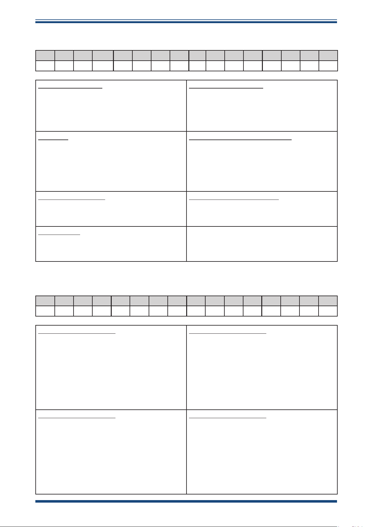
Register Conguration C – System Conguration
15 14 13 12 11 10 9 8 7 6 5 4 3 2 1 0
PP MOD CA PR IT IT TU PU PU N/A MU MU MU
Pressure Units (PU)
00 = Bar.G (def)
01 = Psi.G
10 = Mpag
11 = Spare
Main Unit
0 = Dp (O2 %)
1 = ppmV(I) (O2 ppm)
2 = lbmmscf
3 = mg/m
3
4 = ppmV(N)
Pressure Source (PR)
0 = Sensor
1 = Fixed User
Model (MOD)
0 = Promet
1 = Easidew Advanced
Temperature Unit (TU)
0 = C (def)
1 = F
Instrument Type (IT) – not used
00 = Promet IS
01 = Liquidew IS
10 = Pura
11 = O2
ISO or IGT calculations (CA)
0=IGT
1=ISO
Pressure or ppmV (I) secondary parameter
(PP) – Easidew Advanced only
0 = Pressure
1 = ppmV (ideal)
Register Conguration D – Alarm Conguration
15 14 13 12 11 10 9 8 7 6 5 4 3 2 1 0
A4 A4 A4 A4 A3 A3 A3 A3 A2 A2 A2 A2 A1 A1 A1 A1
Alarm1 Parameter (A1)
0000 = Dewpoint (O2)
0001 = Pressure/Temperature
0010 = ppm
W
0011 = ppmV (Ideal)
0100 = ppmV(Nat Gas)
0101 = mgm
3
0110 = lbmmscf
1000 = Fault
Alarm3 Parameter (A3)
0000 = Dewpoint (O2)
0001 = Pressure/Temperature
0010 = ppm
W
0011 = ppmV (Ideal)
0100 = ppmV(Nat Gas)
0101 = mgm
3
0110 = lbmmscf
1000 = Fault
Alarm2 Parameter (A2)
0000 = Dewpoint (O2)
0001 = Pressure/Temperature
0010 = ppm
W
0011 = ppmV (Ideal)
0100 = ppmV(Nat Gas)
0101 = mgm
3
0110 = lbmmscf
1000 = Fault
Alarm4 Parameter (A4)
0000 = Dewpoint (O2)
0001 = Pressure/Temperature
0010 = ppm
W
0011 = ppmV (Ideal)
0100 = ppmV(Nat Gas)
0101 = mgm
3
0110 = lbmmscf
1000 = Fault
48 97621 Issue 1.4, January 2025
Page 57
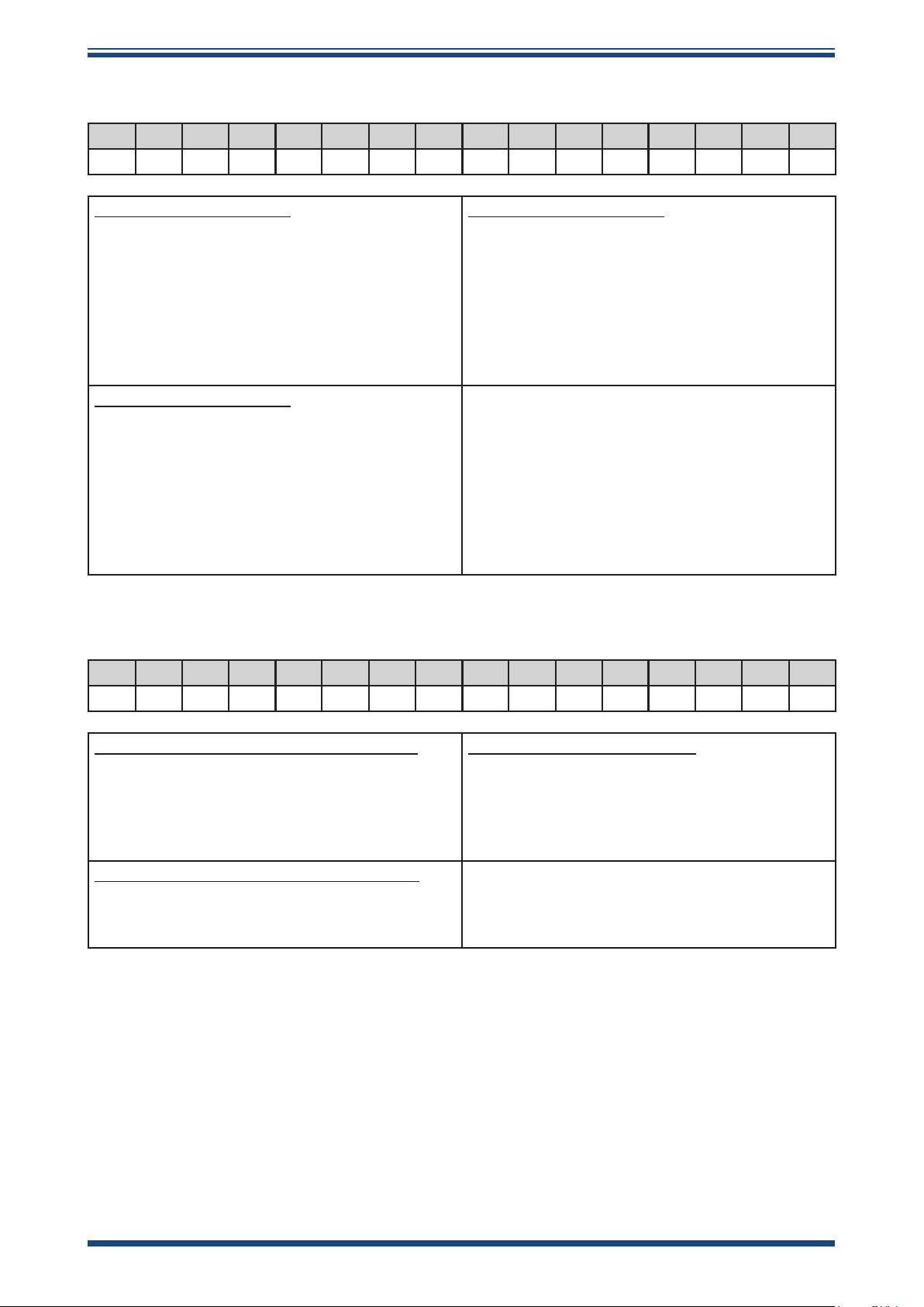
Easidew Advanced Online Hygrometer Manual
APPENDIX B
Register Conguration E – mA Output Cong
15 14 13 12 11 10 9 8 7 6 5 4 3 2 1 0
O3 O3 O3 O3 O2 O2 O2 O2 O1 O1 O1 O1
Ouput1 Parameter (O1)
0000 = Dewpoint (O2)
0001 = Pressure/Temperature
0010 = ppm
W
0011 = ppmV (Ideal)
0100 = ppmV(Nat Gas)
0101 = mgm
3
0110 = lbmmscf
Output2 Parameter (O2)
0000 = Dewpoint (O2)
0001 = Pressure/Temperature
0010 = ppm
0011 = ppmV (Ideal)
0100 = ppmV(Nat Gas)
0101 = mgm
0110 = lbmmscf
Output3 Parameter (O3)
0000 = Dewpoint (O2)
0001 = Pressure/Temperature
0010 = ppm
W
0011 = ppmV (Ideal)
0100 = ppmV(Nat Gas)
0101 = mgm
3
0110 = lbmmscf
Register Conguration F – Status Register
W
3
15 14 13 12 11 10 9 8 7 6 5 4 3 2 1 0
A4 A4 A3 A3 A2 A2 A1 A1 PS DS
Relay Alarm Status ags (A1, A2, A3, A4)
Example:
A1 = 00=OK (relay de-energized)
Dewpoint Sensor Status (DS)
0=OK
1=Fault (or not available)
A1 = 01=High (or Fault)(relay energized)
A1 = 10=Low (relay energized)
Pressure/Temperature Sensor Status (PS)
0=OK
1=Fault (or not available)
Michell Instruments 49
Page 58

APPENDIX B
Easidew Advanced Online Hygrometer Manual
Register Conguration G – Liquid Selection
15 14 13 12 11 10 9 8 7 6 5 4 3 2 1 0
M2 M2 M2 M2 M2 M1 M1 M1 M1 M1 LQ LQ LQ LQ LQ
Liquid Selection (LQ)
0 = n-Butane
1 = n-Propane
2 = n-Hexane
3 = Cumene
4 = Benzene
5 = Toluene
6 = 1-butane
7 = Cyclohexane
8 = Oct-3-ene
9 = Ethylbenzene
10 = Dimethylbenzene
11 = Ethane
12 = Methylcyclohexane
13 = Butylbenzene
14 = Prop-1-ene
15 = But-1-ene
16 = Methane
17 = 2-Methylbutane
18 = USER1
19 = USER2
20 = MIXING
Mixed Liquid 1 (M1)
0 = n-Butane
1 = n-Propane
2 = n-Hexane
3 = Cumene
4 = Benzene
5 = Toluene
6 = 1-butane
7 = Cyclohexane
8 = Oct-3-ene
9 = Ethylbenzene
10 = Dimethylbenzene
11 = Ethane
12 = Methylcyclohexane
13 = Butylbenzene
14 = Prop-1-ene
15 = But-1-ene
16 = Methane
17 = 2-Methylbutane
18 = USER1
19 = USER2
Mixed Liquid 1 (M2)
0 = n-Butane
1 = n-Propane
2 = n-Hexane
3 = Cumene
4 = Benzene
5 = Toluene
6 = 1-butane
7 = Cyclohexane
8 = Oct-3-ene
9 = Ethylbenzene
10 = Dimethylbenzene
11 = Ethane
12 = Methylcyclohexane
13 = Butylbenzene
14 = Prop-1-ene
15 = But-1-ene
16 = Methane
17 = 2-Methylbutane
18 = USER1
19 = USER2
50 97621 Issue 1.4, January 2025
Page 59

Easidew Advanced Online Hygrometer Manual
APPENDIX B
Register Conguration H – Instrument Setup and Command Register (Reg 30)
2 = Set Dewpoint Channel 4 mA ADC Value
3 = Set Dewpoint Channel 20 mA ADC Value
4 = Set Pressure/Temperature Channel 4 mA ADC Value
5 = Set Pressure/Temperature Channel 20 mA ADC Value
10 = Force Analog Output 1...4 mA
11 = Force Analog Output 1...20 mA
12 = Force Analog Output 2...4 mA
13 = Force Analog Output 2...20 mA
14 = Force Analog Output 1...12 mA
15 = Force Analog Output 2...12 mA
16 = Force Analog Output 3...4 mA
17 = Force Analog Output 3...20 mA
18 = Force Analog Output 3...12 mA
19 = All Alarm Relays de-energized
20 = Energize Alarm Relay1
21 = Energize Alarm Relay2
22 = Energize Alarm Relay3
23 = Energize Alarm Relay4
25 = Send Test String to Display Comms Channel
30 = Set control board to default register map values
31 = Enable Setup Mode (Alarms and Analog output updates disabled)
32 = Disable Setup Mode (Alarms and Analog output updates enabled)
Defaults (auto-loaded when PCB is brand new or forced via Modbus)
Easidew
Modbus ID 1
System cong. Main unit = °Cdp
Pressure unit = psig
Pressure source = internal
Fixed pressure = 0.00
Alarm cong. AL1 = dp (low = -120.0, high = -40.0)
AL2 = dp (low = -120.0, high = -60.0)
AL3 = FAULT (low = high = 0.0)
AL4 = FAULT (low = high = 0.0)
Input scale Pressure = 0.0...+100.0
Output cong. OP1 = dp (-120.0...-40.0)
OP2 = Pressure (0.0...+100.0)
OP3 = ppmV (ideal) (0.0...+100.0)
Michell Instruments 51
Page 60

APPENDIX C
Easidew Advanced Online Hygrometer Manual
Appendix C
Quality, Recycling
& Warranty
Information
52 97621 Issue 1.4, January 2025
Page 61

Easidew Advanced Online Hygrometer Manual
Appendix C Quality, Recycling & Warranty Information
Michell Instruments is dedicated to complying to all relevant legislation and directives.
Full information can be found on our website at:
www.ProcessSensing.com/en-us/compliance/
This page contains information on the following directives:
• Anti-Facilitation of Tax Evasion Policy
• ATEX Directive
• Calibration Facilities
• Conict Minerals
• FCC Statement
• Manufacturing Quality
APPENDIX C
• Modern Slavery Statement
• Pressure Equipment Directive
• REACH
• RoHS
• WEEE
• Recycling Policy
• Warranty and Returns
This information is also available in PDF format.
Michell Instruments 53
Page 62

APPENDIX D
Easidew Advanced Online Hygrometer Manual
Appendix D
Return Document &
Decontamination Declaration
54 97621 Issue 1.4, January 2025
Page 63
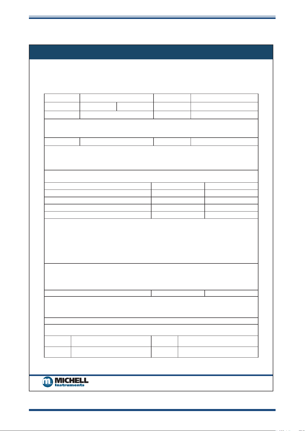
Easidew Advanced Online Hygrometer Manual
Appendix D Return Document & Decontamination Declaration
Decontamination Certicate
IMPORTANT NOTE: Please complete this form prior to this instrument, or any components, leaving your
site and being returned to us, or, where applicable, prior to any work being carried out by a Michell
engineer at your site.
Instrument Serial Number
Warranty Repair? YES NO Original PO #
Company Name Contact Name
Address
Telephone # E-mail address
Reason for Return /Description of Fault:
APPENDIX D
Has this equipment been exposed (internally or externally) to any of the following?
Please circle (YES/NO) as applicable and provide details below
Biohazards YES NO
Biological agents YES NO
Hazardous chemicals YES NO
Radioactive substances YES NO
Other hazards YES NO
Please provide details of any hazardous materials used with this equipment as indicated above (use continuation sheet
if necessary)
Your method of cleaning/decontamination
Has the equipment been cleaned and decontaminated? YES NOT NECESSARY
Michell Instruments will not accept instruments that have been exposed to toxins, radio-activity or bio-hazardous
materials. For most applications involving solvents, acidic, basic, ammable or toxic gases a simple purge with dry
gas (dew point <-30°C) over 24 hours should be sufcient to decontaminate the unit prior to return.
Work will not be carried out on any unit that does not have a completed decontamination declaration.
Decontamination Declaration
I declare that the information above is true and complete to the best of my knowledge, and it is safe for Michell
personnel to service or repair the returned instrument.
Name (Print) Position
Signature Date
F0121, Issue 2, December 2011
Michell Instruments 55
Page 64

www.ProcessSensing.com
 Loading...