

Page 1
TDS0212
Issue 1.1
13/01/2025
Page 1
User Guide
Issue 1.1
Dynament Limited (A PST Brand Company)
Hermitage Lane Industrial Estate ٠ Kings Mill Way ٠ Mansfield ٠
Nottinghamshire ٠ NG18 5ER ٠ UK.
Tel: 44 (0)1623 663636
Axiom Diagnostic Terminal (ADT)
Technical Data Sheet
TDS0212
Page 2

TDS0212
Issue 1.1
13/01/2025
Page 2
Contents
Version History ................................................................................................................................................. 3
Overview ........................................................................................................................................................... 4
AXIOM GAS REFRIGERANT SENSOR .................................................................................................................. 4
Installation ........................................................................................................................................................ 5
AXIOM DIAGNOSTIC TERMINAL REQUIREMENTS ................................................................................................. 5
INSTALLING THE SOFTWARE ............................................................................................................................. 5
Microsoft .Net 8 ........................................................................................................................................ 6
CONNECTION BETWEEN AXIOM AND COMPUTER DEVICE ................................................................................... 6
USB Connection ...................................................................................................................................... 6
RS232 or RS485 Connection .................................................................................................................. 6
USB Connector Pin Out .......................................................................................................................... 7
User Guide ........................................................................................................................................................ 8
CONNECTING TO AXIOM ................................................................................................................................... 8
UNIT STATUS DISPLAY ................................................................................................................................... 10
UNIT CONFIG (AXIOM CONFIGURATION) .......................................................................................................... 10
PROGRAM OPTIONS ....................................................................................................................................... 11
Page 3

TDS0212
Issue 1.1
13/01/2025
Page 3
VERSION HISTORY
Issue
Changes
Changes Made
By
Date
1.0
Initial release of document
K Corcoran
09/09/2024
1.1
Updates to reflect changes to program functionality
K Corcoran
13/01/2025
Page 4

TDS0212
Issue 1.1
13/01/2025
Page 4
OVERVIEW
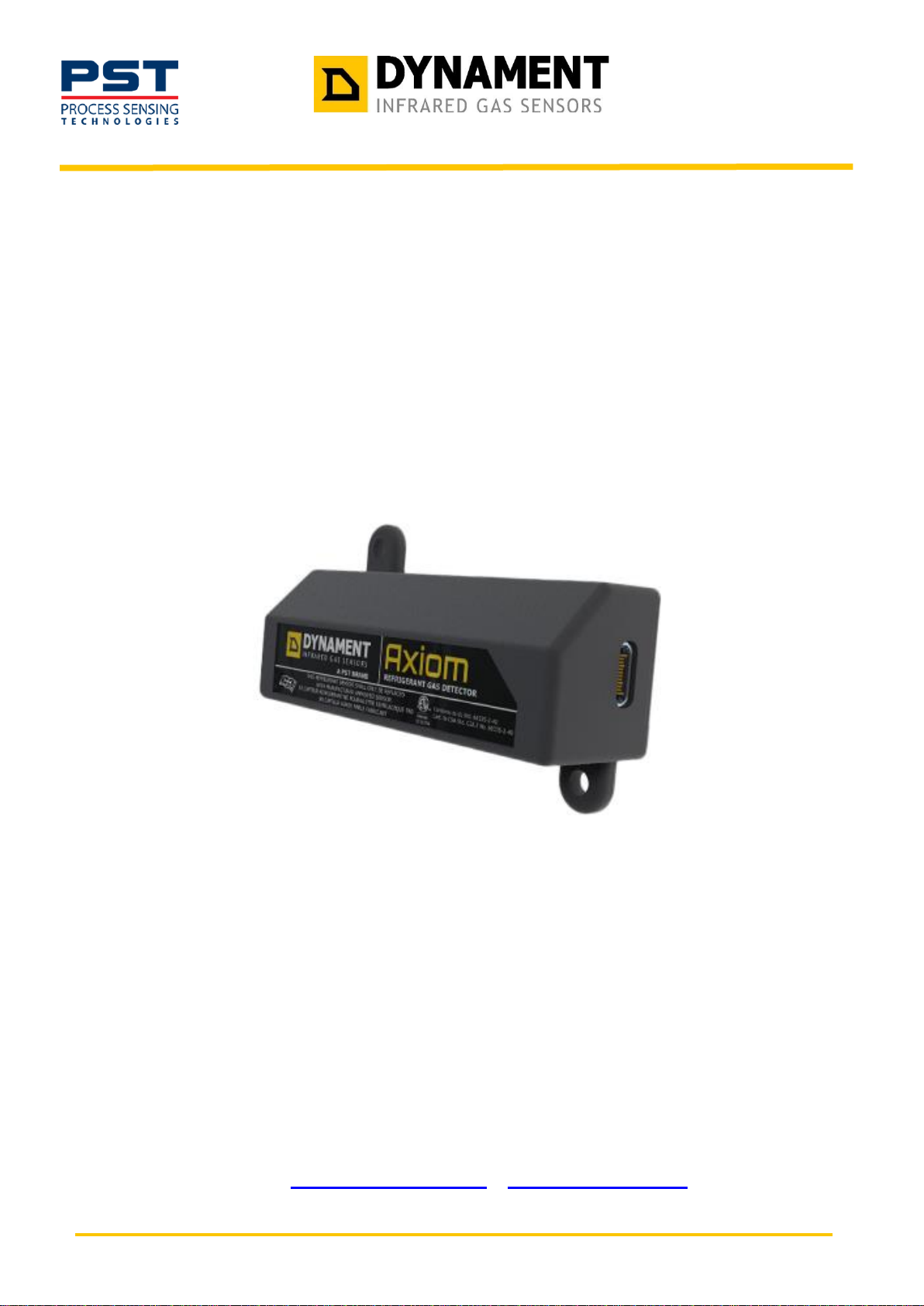
This document describes the operation of the Axiom Diagnostics Terminal (ADT) application to configure and test
Axiom gas refrigerant sensors.
This is an application program designed to run on Windows OS based computers using either an RS232/485 serial
communications interface or a direct USB cable to link to the Axiom sensor.
It allows the user to see the current status of the Axiom and examine error flags, useful to verify correct gas readings
and proper sensor function.
The application also allows the sensor to be configured in terms of the signal output and the address of the sensor
when used in a communications network.
Axiom Gas Refrigerant Sensor
The Axiom sensor is a detector designed specifically to detect the presence of refrigerant gases and to indicate the
level of gas by means of either analogue or digital (serial communication or open collector alarm output) signal.
The USB connector port can also be used for direct communication to a host terminal using a USB-C communications
cable, even when the sensor is configured to adopt an analogue output signal. In this case, the Axiom checks for the
presence of a connected host computer on the USB connector when it first power up and if found, will establish a
communications link with the host. If none is found within 5 seconds, the Axiom will configure the USB connector for
the selected output mode.
Page 5
TDS0212
Issue 1.1
13/01/2025
Page 5
INSTALLATION
This chapter covers the PC hardware and software requirements necessary to be able to run the ADT application
Axiom Diagnostic Terminal Requirements
To run the ADT application, a computer device with the following specification is required :
➢ Microsoft Windows 10/11
➢ 4GB RAM
➢ 4MB free hard disk space
➢ USB port or RS232/RS445 communications adapter (with suitable cable)
Installing the Software
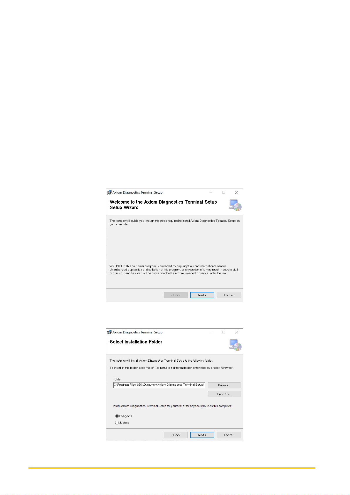
The software is typically provided as a Microsoft Installer File, Axiom Diagnostics Terminal Setup.msi
This file may be provided as a link by email or through the PST/Dynament website.
To install the software, double-click on the file to open it once downloaded. This will start the installation program.
Click Next to continue with the installation.
Accept the default installation options or select an alternative location in which to install the program. Similarly, the
user can determine if this application will be available to all users of the computer or just the currently logged in user.
Page 6

TDS0212
Issue 1.1
13/01/2025
Page 6
Click Next to continue and complete the installation. This will place an icon on the main screen and a new entry in the
computer’s Applications list from which to launch the application.
Microsoft .Net 8
This application requires the Microsoft .Net 8 framework in order to operate. If this is not detected as being installed
on the computer during the installation, then the user will be prompted to downloaded and install the necessary files.
Follow the presented link to download the .Net 8 installation file and then open the downloaded file to complete the
installation, accepting all Default prompts.
Alternatively, the latest .Net 8 framework can be downloaded and installed manually from the following link:
https://dotnet.microsoft.com/en-us/download/dotnet/8.0
Use the link to download the appropriate Windows installation file (Arm64, x64, or x32 – if in doubt use x64). This may
be downloaded as a compressed ZIP file, in which case open the downloaded ZIP file and extract the contents to a
location on the hard disk.
Then run the program dotnet.exe to start the installation of the framework.
Connection Between Axiom and Computer Device
The physical communication between the Axiom sensor the ADT application is by means of either a USB cable or a
serial RS2323 or RS485 communications cable.
USB Connection
This method is the simplest method of communicating with an Axiom sensor. A standard USB type C data cable is
used to connect the Axiom port to a USB port on the computer running the ADT application.
This will create a Virtual COM port on the Windows computer which the ADT application uses to establish
communications. The ADT application can either automatically search for such a port and connect to it, or the user
can manually select the port number if known (see later).
RS232 or RS485 Connection
The Axiom sensors have a USB output connector that can be configured to provide a digital communication output
stream (rather than an analogue output signal) at either RS232 voltage levels (separate Transmit and Receive lines)
or an RS485 muti-drop line (balanced pair single signal for transmit and receive amongst multiple devices).
For such communications, a suitable RS232 or RS485 adapter is required to connect the Axiom to the computer
running the ADT application.
For RS232, the Transmit line from the computer should be connected to the D- line of the Axiom USB connector and
the Receive line to the computer connected to the D+ pin of the Axiom USB connector.
For RS485, the A (sometimes labelled A+) line should be connected to the D+ USB pin of the Axiom and the B line
(labelled B- in some systems) connected to the D- pin of the USB connector.
In both cases, power and ground needs to be applied to the +V and GND pins of the USB connector respectively.
The voltage can be between 5V and 24V DC and the interface adapters typically provide a 5V supply line for this
purpose.
Page 7
TDS0212
Issue 1.1
13/01/2025
Page 7
USB Connector Pin Out
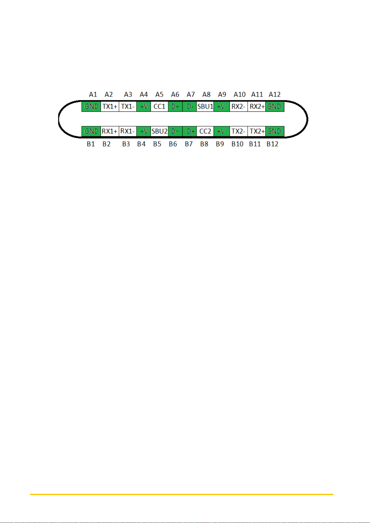
The diagram below shows the pin connections of the USB type C connector on the Axiom. The pins in green are the
ones to connect to in order to enable communications.
Similar pins are connected together, such that you can connect to any GND or +V pin or either D+ or D- pin. You do
not need to connect to all of the pins.
Page 8
TDS0212
Issue 1.1
13/01/2025
Page 8
USER GUIDE
This chapter covers the operation and functions of the ADT application.
Connecting to Axiom
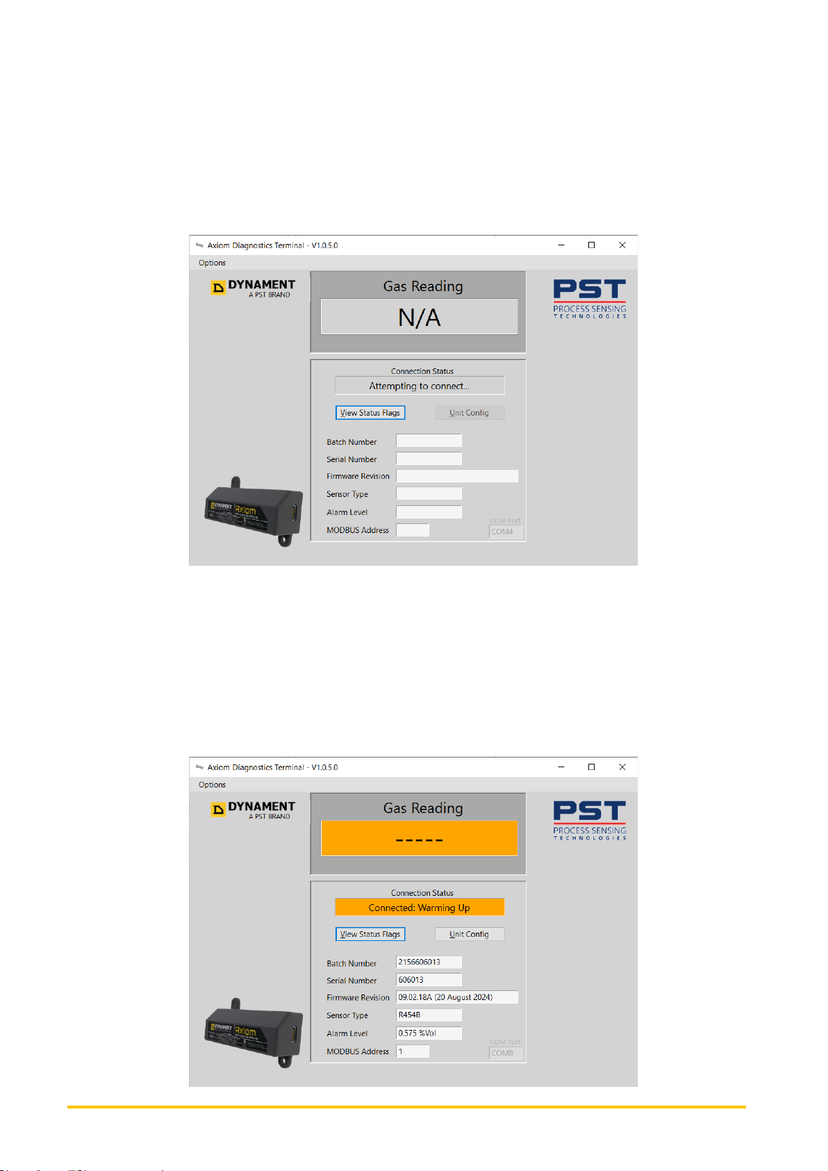
By default, the ADT application will be scanning all physical and virtual COM (communication) ports to find an Axiom
sensor, so once an Axiom is physically connected, the application should find the sensor after a period of time when it
scans the port on which is it actually connected. During this period, the Connection Status indicator will show
“Attempting to Connect…”
The bottom right corner of the main information window shows the COM port currently being scanned. In a computer
with lots of added serial peripherals, there may be many ports so it might be useful to specify which port to use as this
is typically fixed to a specific port on any given computer. Fixing the connection port makes for a quicker time to
connect when an Axiom is plugged in. This can be set in the Program Options function, which is explained in a
chapter below
Once an Axiom is detected, the system will display the information and status of that sensor. If the sensor has just
been plugged in, the screen will show that the sensor is Warming Up. All sensors require a warm-up period, typically
45 seconds from power on, to stabilise the gas reading. During this warm-up period, the gas reading is not shown
whilst the unit stabilises.
Page 9
TDS0212
Issue 1.1
13/01/2025
Page 9
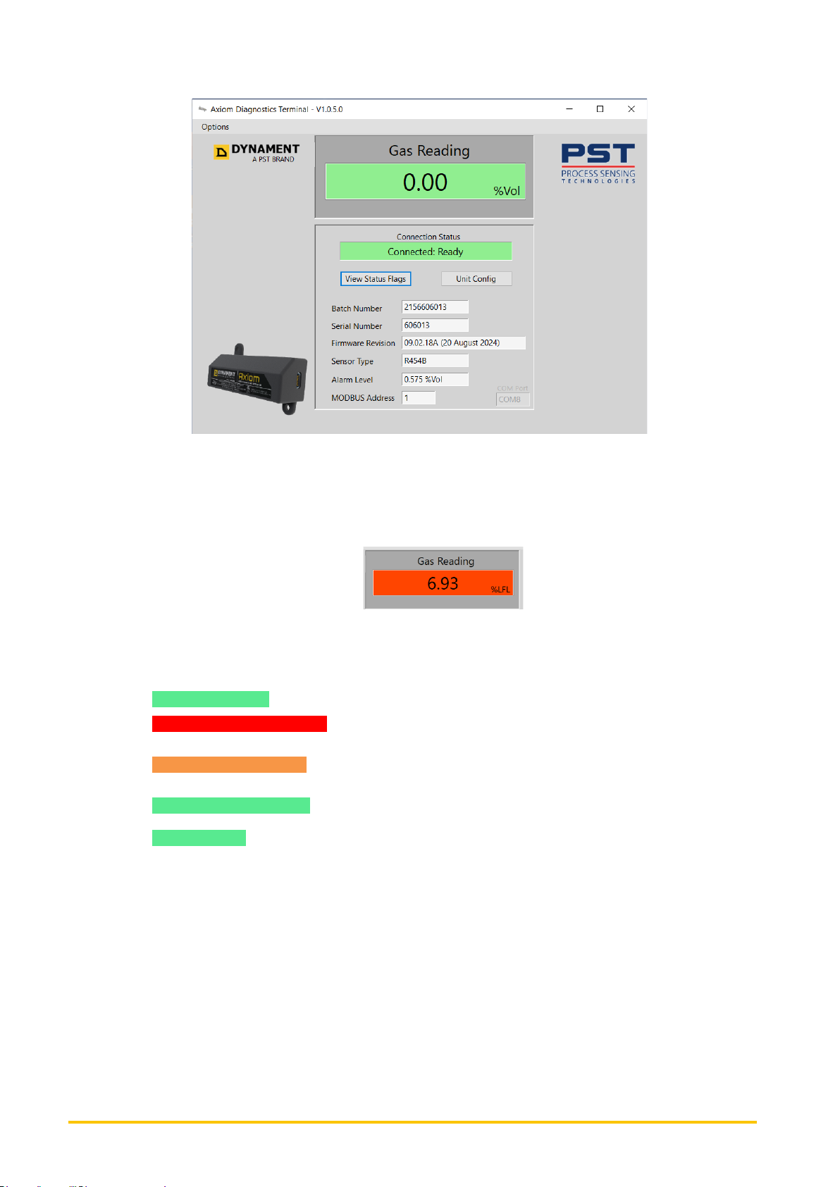
Once the warm-up period has completed, the screen will be showing the current gas reading and general information
as below.
The information fields that are shown are as follows:
➢ Gas Reading – this can be shown as either a %Volume reading or as a %LFL value (or PPM for some
gases). This is selectable in the Program Options. This display will either show a reading with a green
background indicating a valid reading that is under the alarm threshold, or may show a reading with a red
background, indicating that the gas reading has exceeded the sensor’s alarm threshold:
An orange background indicates that the sensor is still warming up after a power on or has detected faults that
prevent a valid gas reading from being determined
➢ Connection Status – this shows the status of the communications link with the Axiom sensor. This can have
the value:
o Connected: Ready – unit is connected and communicating
o Connected: Faults Detected – unit is connected and communicating but the sensor has detected one
or more faults (which can be determined from the View Status Flags button).
o Connected: Warming Up – unit is connected, but the unit has recently powered up and is in the warm-
up period (gas reading value is not valid)
o Attempting To Connect… - system is searching for any connected sensors or waiting for one to be
connected
Not Connected – no unit is attached or the fixed COM port is not available
➢ Batch Number – The unique factory identification number which identifies the manufacturing batch of the
sensor as well as unique ID of the sensor. Useful when talking to Technical Support with regards to this
sensor
➢ Serial Number – serial number of the connected sensor.
➢ Firmware Revision – the version number and date of the sensor’s firmware. Useful when reporting any
issues to Technical Support
➢ Sensor Type – the gas type that the sensor is configured to detect`
➢ Alarm Level – a level (expressed as %Volume or %LFL depending upon options selected) that determines
the alarm threshold. If the gas reading exceeds this level, then an Alarm condition is indicated. If the Open
Collector digital output is utilised, it will be set active whilst in alarm condition and inactive when not.
➢ MODBUS Address – when using serial communications interface (RS232 or RS485), the protocol used for
information transfer is the industry standard open MODBUS protocol. All server/slave devices within the
MODBUS protocol, such as the Axiom, must have a unique address to allow a client system to address the
specific sensor when multiple sensors are connected on the same line. This field shows the configured
address for the connected sensor (values should be set between 1 and 247). The default MODBUS address
is set to 1.
Page 10
TDS0212
Issue 1.1
13/01/2025
Page 10
The View Status Flags and Unit Config button can be used to take a more detailed look at the sensor status and
also allow some simple configuration of the sensor itself.
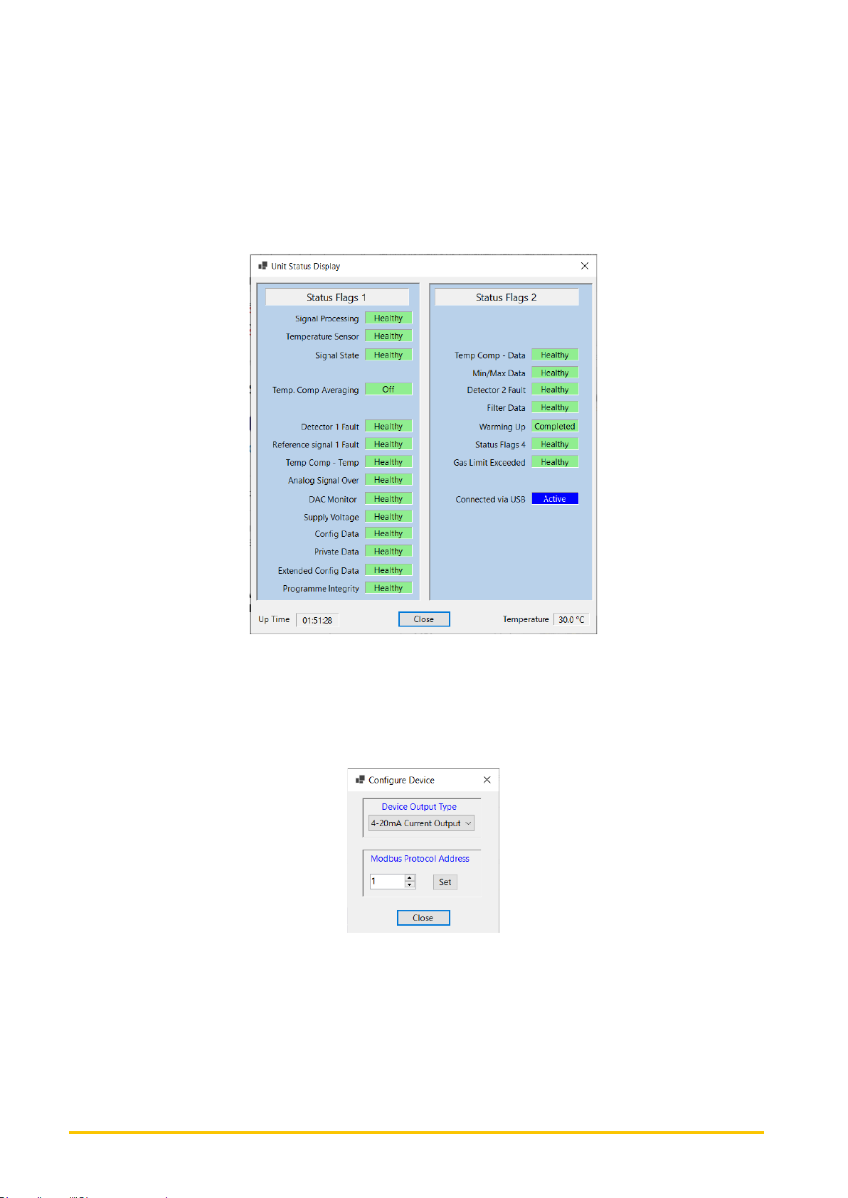
Unit Status Display
This screen shows the individual status flags that the Axiom maintains. This can be useful for the manufacturer in
diagnosing issues, should a sensor not be working as expected.
The details of the individual fields are beyond the scope of this document.
Unit Config (Axiom Configuration)
This function is used to configure some basic parameters of the connected Axiom sensor, such as the
communications address and the output mode.
The parameters that can be set are:
➢ Device Output Type – This defines how the Axiom’s presents the gas reading signal, either as an analogue
signal level (current or voltage) or a digital serial communications signal. Options are:
o 4-20mA Current Output – the value of the gas reading presented as a current signal on the D+ pin of
the USB connector. This indicates the gas reading from 0 (4mA) up to the maximum reading (20mA).
o 0.2V to 4V Voltage Output – the value of the gas reading presented as a voltage signal on the D+ pin
of the USB connector. This indicates the gas reading from 0 (0.2V) up to the maximum reading (4.0V).
Page 11
TDS0212
Issue 1.1
13/01/2025
Page 11
o RS485 Serial (Modbus) – digital communications interface using the industry standard Modbus
protocol using RS485 signal levels. Can be used in a multi-drop system of multiple sensors on a
single line. The D+ and D- pins of the USB connector provide the balanced pair signal transmission
lines.
o RS232 Serial (Modbus) – digital communications interface using the industry standard Modbus
protocol using RS232 signal levels. This would typically be used in a one to one system where a host
is connected directly to the sensor. The D+ and D- pins of the USB connector provide the Tx and Rx
lines of the RS232 interface respectively
➢ Modbus Protocol Address – The unique address of the Axiom sensor when it is communicating using the
Modbus protocol. Eash sensor or server device on a network has a unique address between 1 and 247 that
allows multiple sensors to be connected together and addressed dividually by the client device.
Program Options
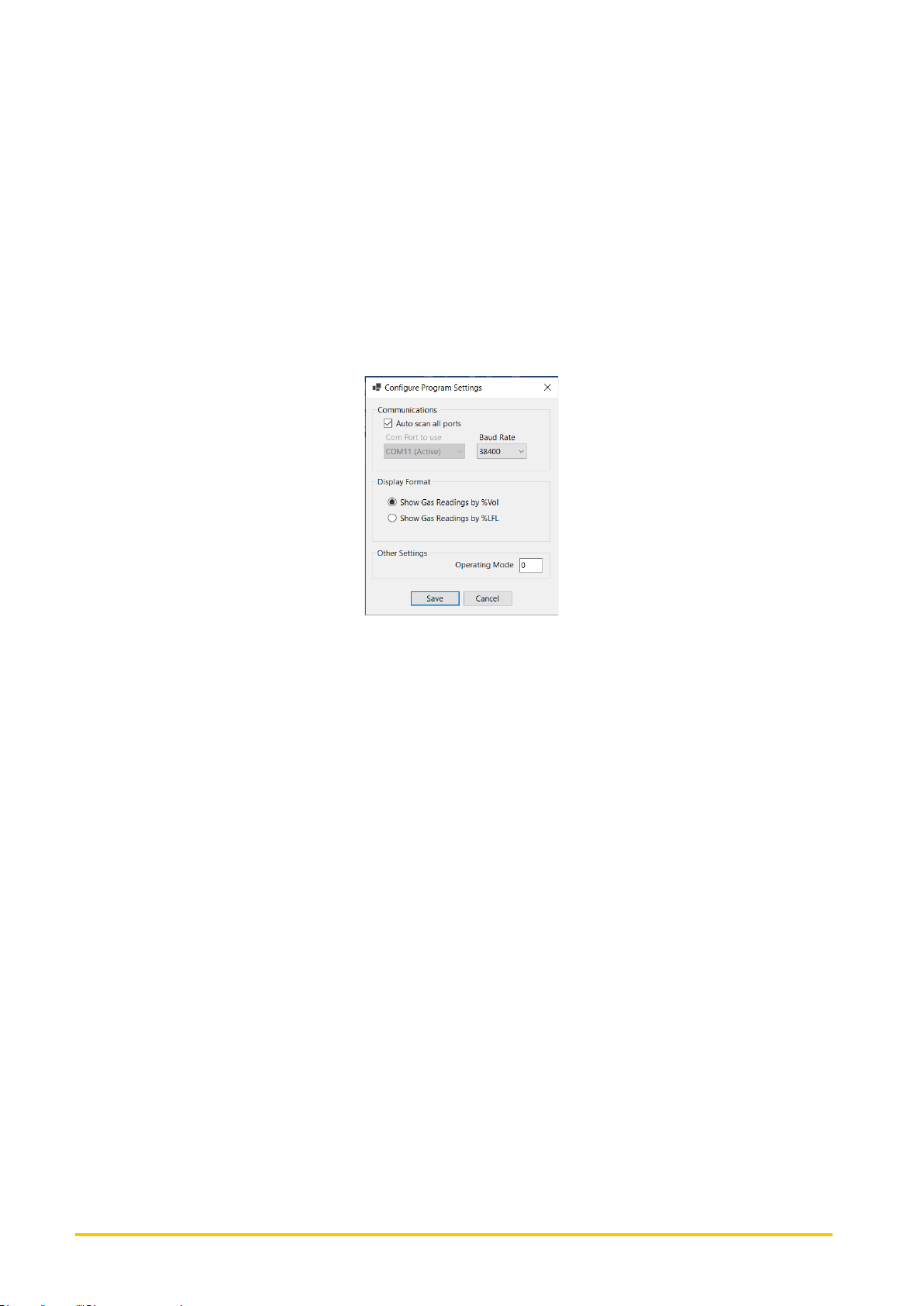
The Options menu of the application contains a Settings menu item that allows some of the application parameters to
be set, including the communications port, link speed and display format.
The available settings are as follows:
Communications
➢ Auto-scan all ports – if set, then the application will continuously scan all communication ports searching for
a connected Axiom sensor until it finds one, at which point it locks onto that port and commences regular
dialogue with the sensor. When the sensor is removed, the application returns to scanning all available ports
for connected sensors. If not checked, then the application only scans for sensors on a specific port (as
selected below). When the communication port is known, it makes for quicker connection times to specify the
port. When connected to a sensor, the main screen status display shows the connected COM port, so this
could be selected once known to speed up connection for future sensors.
➢ COM Port to use – if auto-scan is not enabled (see above), then this field determines which communications
(or COM) port to connect to. No other ports will be scanned. Typically, when connecting to sensors using a
USB cable or through an RS232/RS485 adaptor, the COM port will always be the same, so turning off autoscanning and selecting the port here means that the application will connect quicker when a sensor is plugged
in, as it doesn’t need to search any other ports to check for connection.
➢ Baud Rate – this determines the speed of the communications link, which is typically set to 38,400 bits per
second. Sensors can be ordered with alternative baud rates and this field allows the application to be used
with any sensor configured for different speeds.
Display Format
➢ Show Gas Readings by %Vol – selecting this option ensures that all gas readings (and associated
parameters such as alarm threshold) are shown as %Volume values (or PPM for certain gas types).
➢ Show Gas Readings by %LFL – selecting this option shows gas readings as %LFL (Lower Flammable Limit)
figures. For example, for RS454B gas, the alarm threshold is set to 5%LFL by default, which equates to a
%Volume figure of 0.575 %Vol as the LFL value is 11.5 %Vol for this gas.
Other Settings
➢ Operating Mode - this parameter is used to enable certain factory specific operating modes and is beyond
the scope of this document.
 Loading...