

Page 1
®
An OMEGA Technologies Company
®®®®®®®®®®®®®®®
DWT1305D Series
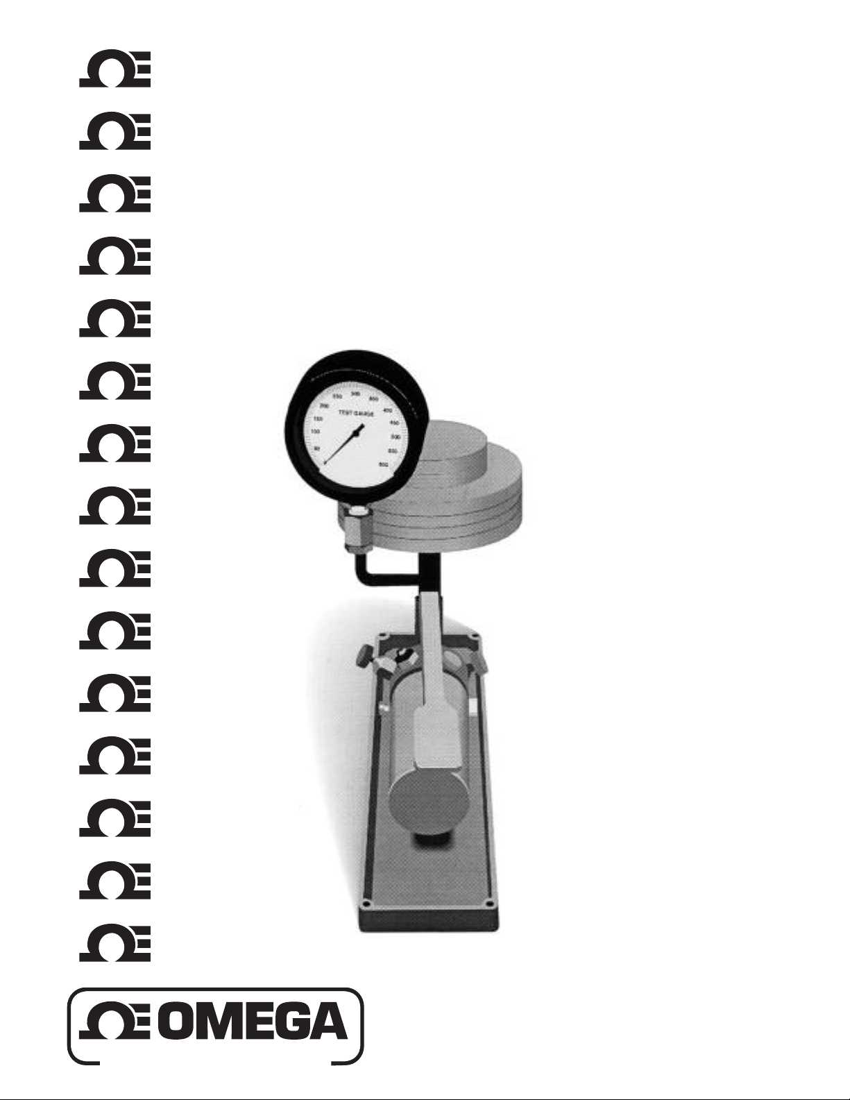
Deadweight Tester
DWT1327D
Portable Pressure Test Set
Deadweight Tester
Operator’s Manual
Rev 1.3 7/13
Page 2
omega.comomega.com
TM
®
OMEGAnet®On-Line Service Internet e-mail
www.omega.com [email protected]
Servicing North America:
USA: One Omega Drive, P.O. Box 4047
ISO 9001 Certified Stamford CT 06907-0047
TEL: (203) 359-1660 FAX: (203) 359-7700
e-mail: [email protected]
Canada: 976 Bergar
Laval (Quebec) H7L 5A1
TEL: (514) 856-6928 FAX: (514) 856-6886
e-mail: [email protected]
For immediate technical or application assistance:
USA and Canada: Sales Service: 1-800-826-6342 / 1-800-TC-OMEGA
Customer Service: 1-800-622-2378 / 1-800-622-BEST
Engineering Service: 1-800-872-9436 / 1-800-USA-WHEN
TELEX: 996404 EASYLINK: 62968934 CABLE: OMEGA
Mexico: Tel: (001) 800-826-6342 FAX: (001) 203-359-7807
En Espan˜ol: (001) 203-359-7803 e-mail: [email protected]
®
®
®
Servicing Europe:
Benelux: Postbus 8034, 1180 LA Amstelveen, The Netherlands
TEL: +31 (0)20 6418405 FAX: +31 (0)20 6434643
Toll Free in Benelux: 0800 0993344
e-mail: [email protected]
Czech Republic: Rudé armády 1868, 733 01 Karviná
TEL: +420 (0)69 6311899 FAX: +420 (0)69 6311114
Toll Free in Czech Rep.: 0800-1-66342 e-mail: [email protected]
France: 9, rue Denis Papin, 78190 Trappes
TEL: +33 (0)130 621400 FAX: +33 (0)130 699120
Toll Free in France: 0800-4-06342
e-mail: [email protected]
Germany/Austria: Daimlerstrasse 26, D-75392 Deckenpfronn, Germany
TEL: +49 (0)7056 3017 FAX: +49 (0)7056 8540
Toll Free in Germany: 0800 TC-OMEGA
e-mail: [email protected]
United Kingdom: One Omega Drive, River Bend Technology Centre
ISO 9002 Certified Northbank, Irlam, Manchester
M44 5EX, United Kingdom
TEL: +44 (0)161 777 6611 FAX: +44 (0)161 777 6622
Toll Free in the United Kingdom: 0800 488 488
e-mail: [email protected]
SM
It is the policy of OMEGA to comply with all worldwide safety and EMC/EMI regulations that
apply. OMEGA is constantly pursuing certification of its products to the European New Approach
Directives. OMEGA will add the CE mark to every appropriate device upon certification.
The information contained in this document is believed to be correct, but OMEGA Engineering, Inc. accepts
no liability for any errors it contains, and reserves the right to alter specifications without notice.
WARNING: These products are not designed for use in, and should not be used for, patient-connected applications.
CJS0296FSBA
Page 3

Omega®Installation and Maintenance Manual
for the Omega
®
Type DWT1305D Deadweight Tester
and Type DWT1327D Portable Pump
INDEX
Section Description
1. Scope of Manual Safety Precautions
2. Product Description DWT1305
Theory of Operation
Construction
Specifications
Product Description DWT1327
Theory of Operation
Construction
Specifications
3. Inspection
Installation DWT1305
Operation DWT1305
Installation DWT1327
Operation DWT1327
4. Factors Affecting Operation of Deadweight
Testers
5. Maintenance Instructions
Shipping Instructions
List of Illustrations
Figure 1-1
Figure 1-2
Figure 2-1
Figure 5-1
1.0 PURPOSE AND SCOPE OF MANUAL
This manual is provided to guide users of Model
DWT1305D and DWT1327D pressure testing devices in:
(1) installing the equipment
(2) Routine operations
The instructions in this manual are designed to be performed by qualified instrument maintenance personnel.
Omega Engineering does not recommend troubleshooting
or repairs beyond the scope of this manual. Problems that
cannot be remedied by following the instructions in this
manual should be referred to Omega. Immediate assistance can often be supplied by telephone. Defective components will be repaired or replaced as necessary.
Returned goods should be accompanied by information
requested in Section 6.
1.1 Safety Precautions
Pressure Testing Equipment must be selected and used in
accordance with recognized industry codes and safety
practices to avoid the possibility of misuse or misapplication which could result in personal injury or property damage. Personnel responsible for selection and installation
should also be familiar with the safety recommendations of
ASME B40.1 that apply to elastic pressure elements and
their application in general and specific services.
1. Pressure – Select a range so that the maximum
applied pressure will never exceed the upper range limit.
2. Vibration – Excessive vibration could cause a loosening of components and abnormal wear resulting in loss of
instrument accuracy or failure to provide valid data.
3. Temperature – Operation of the instrument in an environment where temperatures are in excess of design ratings may result in loss of accuracy and failure.
4. Process – Pressure boundary materials must be resistant to the process media. Failure to assure compatibility
may result in pressure boundary deterioration or failure.
Instruments operated at high pressure or with potentially
hazardous service, such as oxygen, should be carefully
selected in accordance with recognized industry codes
and the recommendations of ASME B40.1.
2.0 PRODUCT DESCRIPTION –
THEORY OF OPERATION – CONSTRUCTION
2.1.2 Product Description
2.1.3 Construction
The Omega Type DWT1305D Dual Range Deadweight
testers are precision built primary pressure standards,
used for testing, setting, calibrating or repairing pressure
measuring devices within the test points 15 psi (100kPa)
to 10,000 psi (70,000kPa).
The deadweight tester consists of a two stage hydraulic
pump containing a manifold which is pressurized during
operation. Integral to the pump is a shuttle valve that
allows the operator to regulate the speed of pressure
increase. One connection to the manifold includes a cylinder and a free-floating precision machined piston with a
plate for holding calibrated weights. A second connection
to the manifold accommodates a gauge or other pressure
measuring device to be calibrated or checked.
Incorporated into the manifold is a hand operated displacement valve that allows small adjustments in fluid volume to be made without further operation of the pump
handle or release valve.
The tester is dual range having two interchangeable piston
Page 4
and cylinder assemblies. One is a low pressure piston having an effective area five times larger than that of the high
pressure piston. The low pressure piston is used for making measurements below 2,000 psi (14,000 kPa). The high
pressure piston, with an area 1/5 that of the low pressure
piston, is used to measure pressure through 10,000 psi
(70,000 kPa). The weight masses are pre-measured and
identified with the pressure values they produce when
operated with the interchangeable piston and cylinder
assemblies.
Pressure calibration points produced by the deadweight
tester are accurate to within ± 0.1% of the reading certified
traceable to the National Institute of Standards and
Technoogy (NIST). The tester provides consistent, repeatable accuracy, maintaining its pressure for an appreciable
length of time regardless of temperature changes, slight
leaks in the pressure system, or changes in volume of the
pressurized system due to movement of a Bourdon tube
or other device.
A hand jack set, three wrenches, spare O-rings, and a
special adapter for making connections to pressure outlets
that do not accommodate cone pipe seating, are included
with each unit.
All deadweight testers are supplied with lower and back
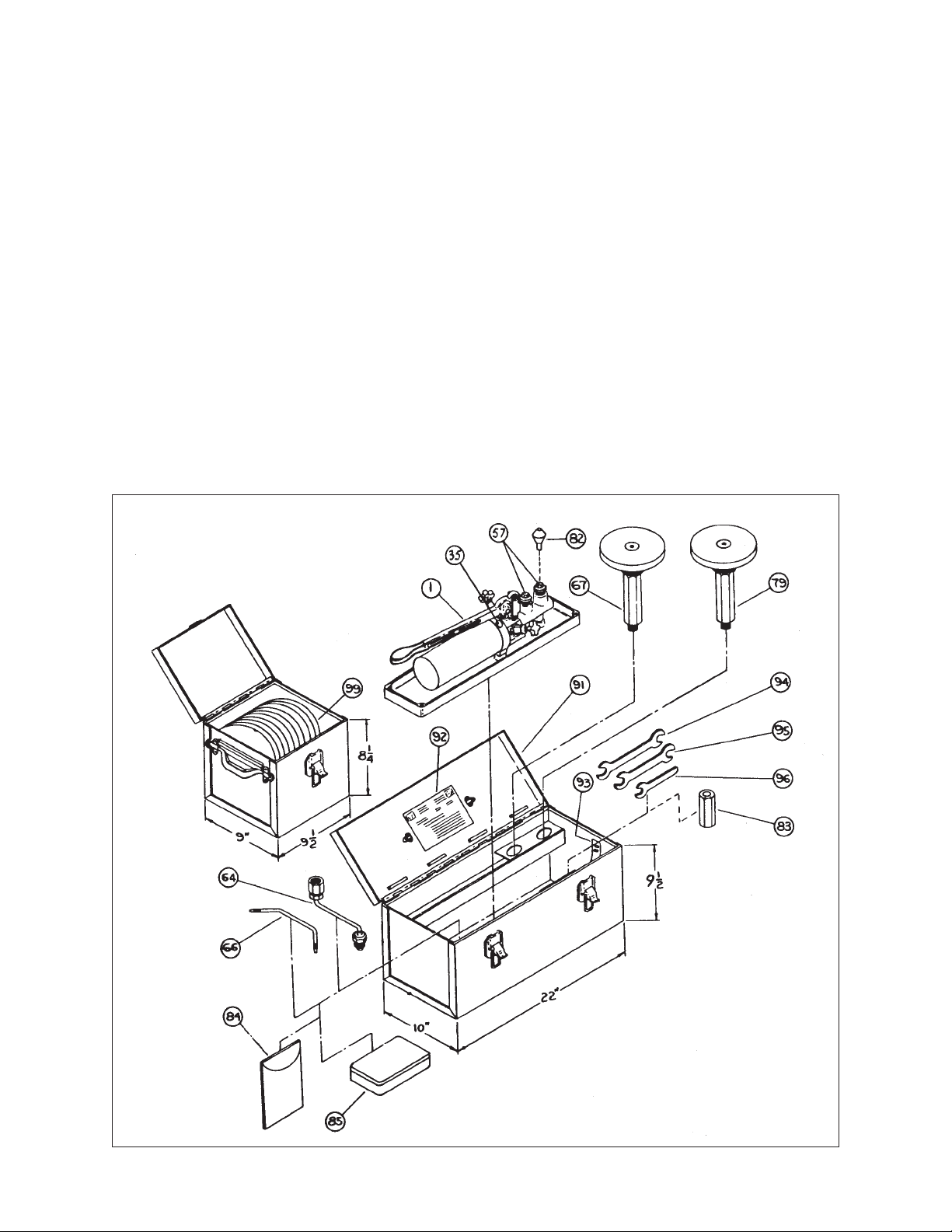
Figure 1-1 Omega Portable Dual Range Deadweight Tester – Type DWT1305
connection offset pipe assemblies, with pipe adapters for
1
⁄
4 NPT or
1
⁄
2 NPT connections.
An all metal, double-latched, top handle carrying case is
supplied with the complete tester for all fittings and attachments. Deadweights are packed in metal, double-latched
storage-carrying boxes.
2.1.2 Theory of Operation – DWT1305D
The theory behind a deadweight tester can be expressed
as simply as force acting upon a known area. Pressure
produced by the pump is distributed by the manifold, to the
base of a precision machined piston and to a device being
calibrated or checked. Pre-selected weights loaded onto
the piston platform are acted upon by gravity and develop
a force that is to be equally opposed by the fluid pressure
from the pump. When equilibrium is achieved, the pressure value is known, it being a direct result of the sum of
the forces from the weights, piston platform and the piston
divided by the effective area of the piston and cylinder
assembly.
With the DWT1305D two piston and cylinder assemblies
are supplied, one having an effective area 1/5 of the other.
When using the smaller piston and cylinder assembly, five
times more pressure is required to oppose the force of a
constant mass being acted upon by gravity. For this reason
Page 5

the masses supplied with the tester are stamped with two
pressure values, the value being contingent on the effective area of the piston and cylinder assembly selected.
2.1.3 Specifications – DWT1305D
Accuracy: Combined tolerance of weights and piston and
cylinder assemblies within 0.1% of reading. Weight tolerance within 0.05% of mass. Piston and cylinder is within
0.05% of rated mean effective area.
Deadweight: Non-magnetic die cast zinc alloy. Total
weight to produce maximum pressure of 10,000 psi
(70,000kPa) is 125 lbs. (56.7 kg).
Piston & Cylinder Assemblies: High strength stainless
steel piston and cylinder with brass collar and aluminum
weight platform.
Pump: Two stage, lever operated generates 10,000 psi
(70,000 kPa) with 28 pounds (12.7 kg) of force on lever
handle.
Pump Body: Aluminum, corrosion inhibited and coated
with baked blue epoxy finish.
Shuttle Valve: Stainless steel bypass valve that controls
rate of pressure increase and reduces operator effort
when working at high pressure.
Displacement Valve: A fine pitched threaded valve rod
permitting vernier adjustments to fluid volume and provide
precise pressure changes or adjustment of piston travel.
Limit stops prevent rod removal during normal operation.
Mounting: Four bench mounting holes located in base for
positive mounting to any level surface.
Instrument Connections: Two coned pipe assemblies
provide vertical calibration capability for back and lower
connected gauges. Standard
1
⁄4 inch internal NPT and 1⁄2
inch inter NPT fitting adapters are supplied.
Operating Fluid: DWT1305D – Light grade machine oils,
automotive petroleum base SAE 20 oils or other equivalent fluids suitable for use with Buna N O-ring materials.
1.5 pints required (.7 liters).
2.1.4 Certification:
Standard – Certificate of NIST traceability
(accuracy/traceability statement only).
Optional (CAL-3) – Certification document includes actual
(as left) weight values for each weight and piston, piston
diameter values, environmental data and NIST test
numbers. Set includes numbered weights.
2.2 Product Description DWT1327D
Page 6
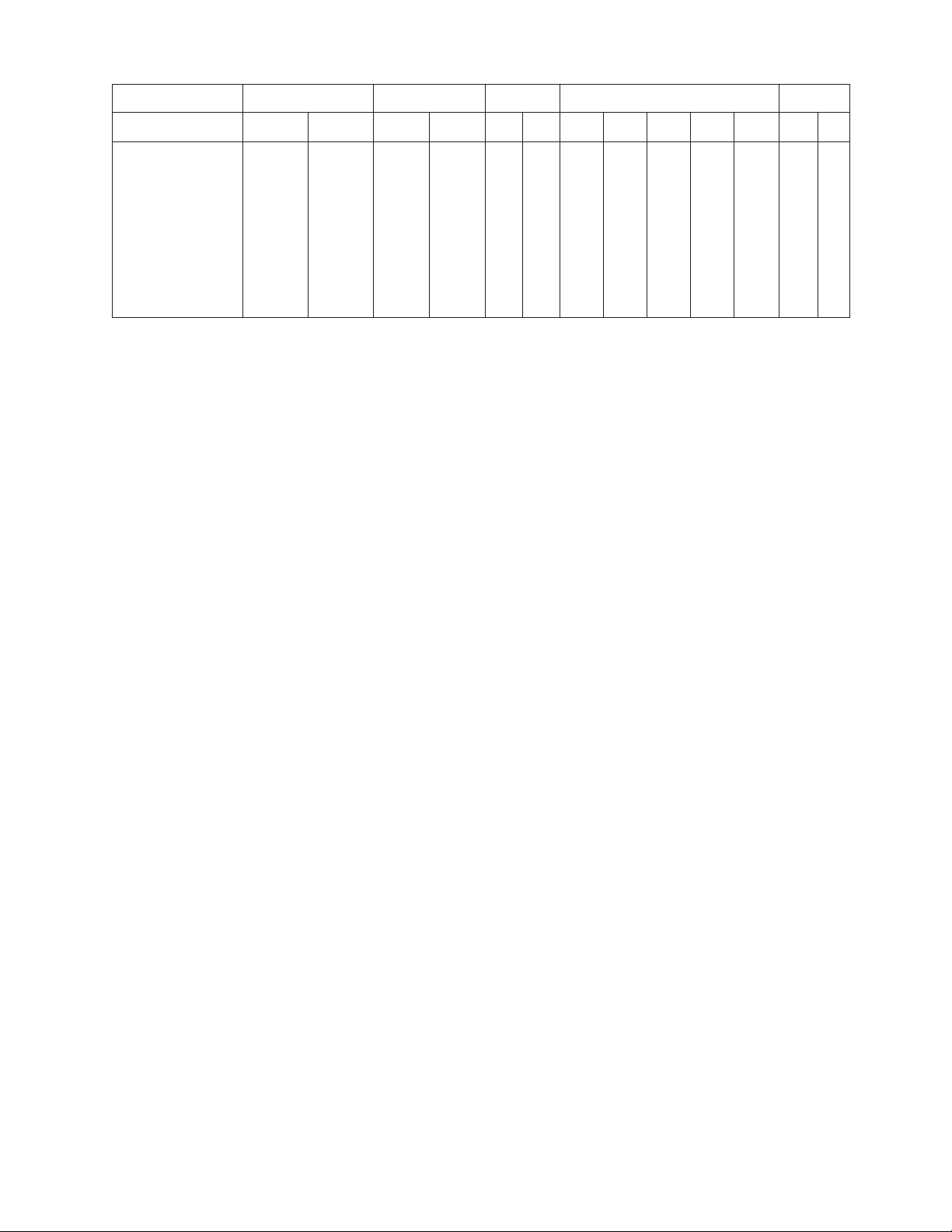
Model Piston Assembly Piston Net
Number Pressure Range Piston Area Value Number of Weights by Value Weight
L-5 L-10 L-20 L-40 L-100
psi Type Low High Low High Low
High
H-25 H-50 H-100 H-200 H-500
lbs. kg.
DWT1305D-10
DWT1305DH-10 15/200 75/1000 5 25 1323-- 60 27
DWT1305D-20
DWT1305DH-20 15/400 75/2000 5 25 1323270 32
DWT1305D-30 .
0625 in.2.0125 in.
2
DWT1305DH-30 15/600 75/3000 (.4032) (.0806) 5 25 1323485 39
DWT1305D-50
DWT1305DH-50 15/1000 75/5000 5 25 13238105 48
DWT1305D-100
DWT1305DH-100 15/2000 75/10000 5 25 132318 175 80
Dimensions in ( ) are square centimeters
TABLE 2-1
Page 7
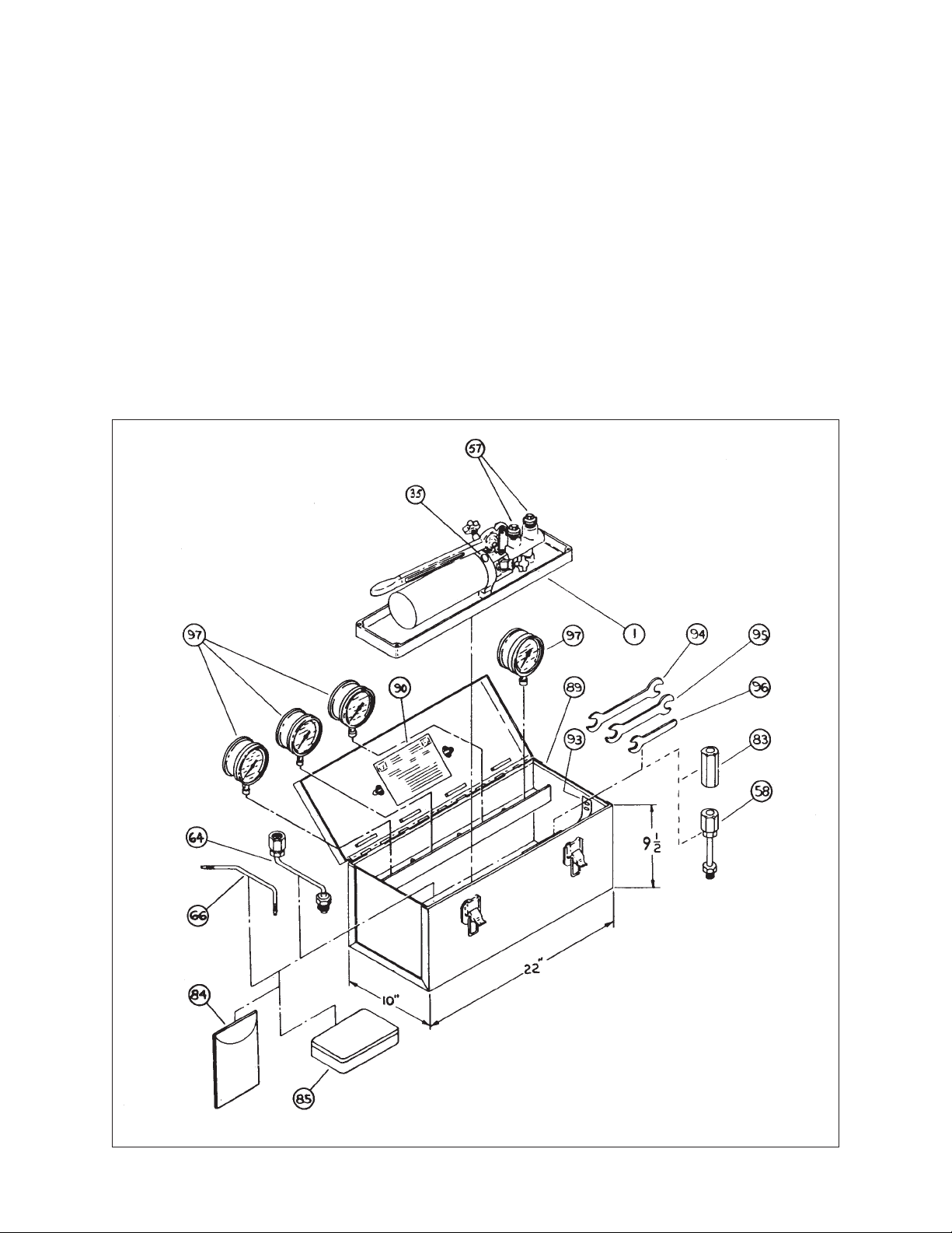
2.2.1 Construction
The Omega Type DWT1327D Portable Test Pumps are
rugged, versatile pressure transfer standards, used for
testing, setting, calibrating or repairing pressure measuring devices with ranges up to 10,000 psi (70,000kPa). A
selection of high accuracy test gauges, with a precision of
±0.25% of span, are available as the standard to which the
device under test is compared.
The main component to the tester is a two stage hydraulic
pump containing a manifold which is pressurized during
operation. Integral to the pump is a shuttle valve that
allows the operator to regulate the speed of pressure
increase. One connection to the manifold has a straight
pipe with a precision test gauge attached serving as the
reference standard. A second connection to the manifold
accommodates a gauge or other pressure measuring
device to be calibrated or checked. Incorporated into the
Figure 1-2 Omega Portable Test Pump – Type DWT1327
manifold is a hand operated displacement valve that
allows small adjustments in fluid volume to be made without further operation of the pump handle or release valve.
Pressure values produced by the pump are able to be
clearly read to within ±0.25% accuracy of the span of the
precision test gauge selected for testing. A hand jack set,
three wrenches, spare O-rings, and special adapter for
making connections to pressure outlets that do not accommodate cone pipe seating, are included with each unit.
Test pump accessories include lower and back connection
offset pipe assemblies, with pipe adapters for
1
⁄
4 and
1
⁄
2
NPT connections.
An all metal, double-latched, top handle carrying case is
supplied with the complete tester to hold all fittings and
attachments.
2.2.2 Theory of Operation – DWT1327D
Note: (97) Gauges are not provided with
the set and may be ordered separately.
Page 8

The operating principle behind the DWT1327D Test Pump
is a simple form of comparison. Pressure produced by the
pump is equally distributed by the manifold to a test gauge
and to a device being calibrated or checked. The reading
of the test gauge serves as the reference to which other
device readings are compared.
Selection of the test gauge range is the determining factor
in establishing the precision to which a comparison check
is to be made. Test gauge accuracy is expressed as a percentage of its span.
Proper selection of the test gauge range must be made to
minimize the amount of the unit error. If a 5,000 psi
(35,000kPa) range test gauge were used to test devices
whose span values were less than a fourth of the test
gauge range, the unit error of 12.5 psi (87kPa) would be
greater than 1% of the test pressure. Therefore, it is important to select a test gauge that has a full scale range equal
to or only slightly in excess of the pressure value to be
measured.
2.2.3 Specifications – DWT1327D
Accuracy:
Test Gauges: Omega PGT45L 4
1
⁄
4% of 1% of test gauge span.
1
⁄
2˝ test gauges are
recommended.
Pump: Two stage, lever operated generates 10,000 psi
(70,000kPa) with 28 pounds (12.7kg) of force on lever
handle.
Pump Body: Aluminum, corrosion inhibited and coated
with baked blue epoxy finish.
Shuttle Valve: Stainless steel bypass valve that controls
rate of pressure increase and reduces operator effort
when working at high pressure.
Displacement Valve: A fine pitched threaded valve road
permitting vernier adjustments to fluid volume to provide
precise changes. Limit stops prevent road removal during
normal operation.
Mounting: Four bench mounting holes located in base for
positive mounting to any level surface.
Instrument Connections: Two coned pipe assemblies
provide vertical calibration capability for back and lower
connected gauges. Standard
1
⁄
4 inch internal NPT and
1
⁄
2
inch internal NPT fitting adapters are supplied.
Operating Fluid: DWT1327D – Light grade machine oils,
automotive petroleum base SAE 20 oils or other equivalent fluids suitable for use with Buna N O-ring materials.
1.5 pints required (.7 liters).
2.2.4 Certification:
Exclusively dependent upon certification provided with test
instrument.
3.0 SETTING UP THE TESTER
Page 9

3.1 Inspection
3.1.1 Component Check DWT1305D
The deadweight tester, as shipped from the factory, contains all of the components necessary for operation except
pump fluid and the test instrument(s). Figure 1-1 provides
an illustrated breakout of these items for quick verification.
3.1.2 Component Check DWT1327D
The portable test pump, as shipped from the factory, contains all of the components necessary for operation except
pump fluid. Figure 1-2 provides an illustrated break-out of
these items for quick verification.
3.1.3 Claim for Missing or Damaged Goods
In the event it is determined that an item is missing or
damaged, contact Omega Engineering immediately.
Disposition of damaged or missing goods will be provided
at that time.
3.2 Installation Type DWT1305D
3.2.1 Set-up Procedure (See Figures 1-1 and 2-1)
To remove the tester from the case, release the spring clip
(93), depressing the clip by hand, grasp the pump reservoir and lift up the back end of the pump assembly.
Having removed the pump assembly from its carrying
case (91), remove the two plastic shipping plugs (57).
Select a lower connection (64) or back connection (66) offset pipe and connect to inner pump body outlet as shown
in Fig. 2-1.
Remove the reservoir filler plug (35) and fill reservoir with
operating fluid.
3.2.2 Bench Space Required (See Figure 1-1)
Allow a space:
10 inches (25.4 cm) width
27 inches (68.6 cm) depth
22 inches (55.9 cm) height – allows for maximum load of
deadweights
3.2.3 Storage Space Required
One Tester Box:
1
⁄
2 inch (2.6 cm); 22
10
1
⁄
2 inch (57 cm) depth; 10 inch (25
cm) height
One Weight Box:
10 inch (25 cm) width; 10 inch (25 cm); 10 inch (25 cm)
height
Storage space dimensions are larger than actual size of
tester carrying case and deadweight carrying case by
approximately _ inch, (1.3 cm), in order to facilitate ease of
handling in storage.
Note: For catalog numbers DWT1305D, DH-100, allow
storage space for two weight boxes.
Page 10
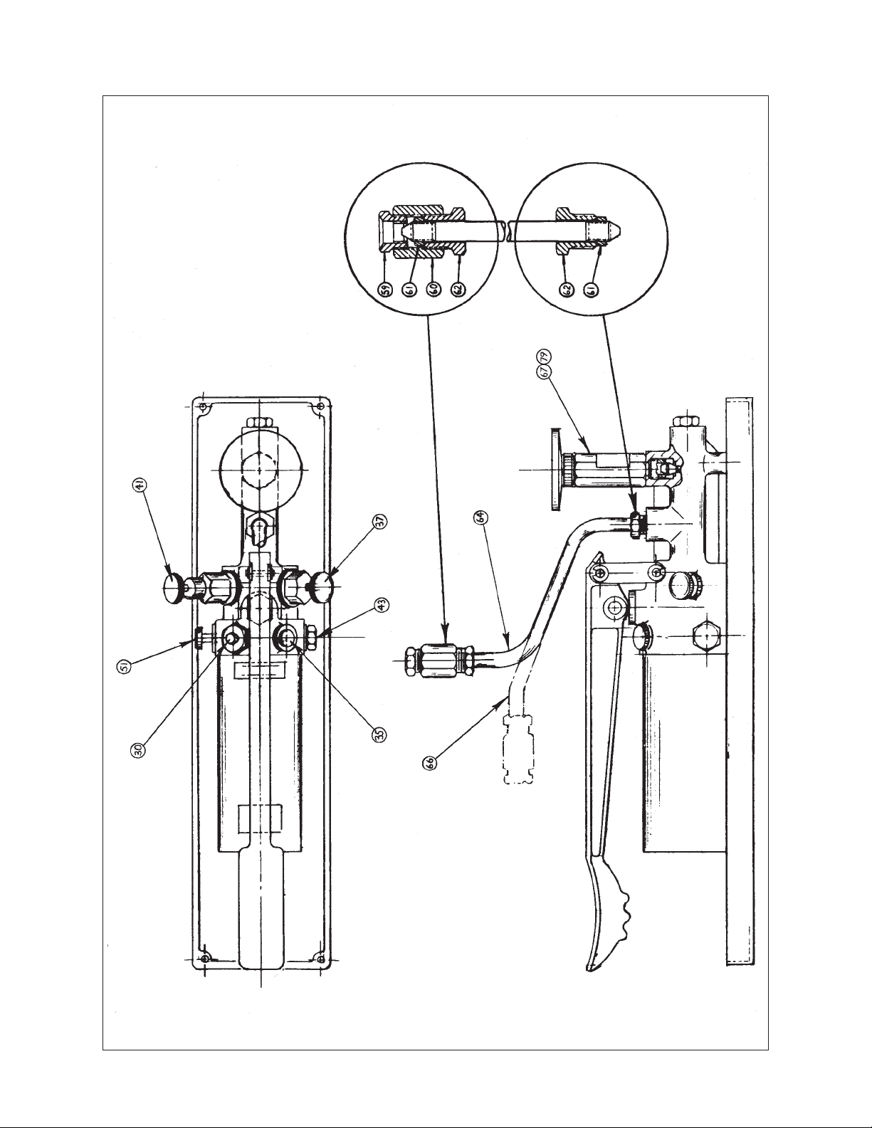
Figure 2-1 Omega Portable Deadweight Tester DWT1305D
Page 11

3.3 Operation DWT1305D
3.3.1 Piston and Cylinder Selection
The DWT1305D Tester is a dual range device in that most
models utilize two interchangeable piston and cylinder
assemblies for measurement of pressure throughout the
entire range. Each piston and cylinder assembly has a
minimum and maximum operating range. First, determine
what pressure points need to be measured and select the
appropriate assembly. The pressure range of the assemblies is shown in Table 2-1. When priming the pump the
high pressure piston and cylinder assembly should be used.
3.3.2 Priming the Pump
The offset pipe (64 or 66 Figure 2-1) should already be
secured in place and the reservoir should contain the
operating fluid (refer to Installation Section 3.2).
Close the release valve (37) by turning it clockwise and
open the air vent by loosening the filler plug (35) a few
turns. The shuttle valve (51) should be pulled outward from
the pump body, the end of the knob approximately even
with the edge of drip pan. In this position the high volume
displacement mode is selected and the pump is self-priming. Operate the pump handle several times using full
strokes, until you see fluid appear in the outer pump body
outlet.
The cone seat (82) is located in the base of the outerpump body outlet and serves as the sealing surface
between the bottom of the piston and cylinder assembly
and the pump body. Confirm the coned end of the seat is
facing up and the cylindrical end of it is facing down.
Thread the high pressure piston and cylinder assembly
(79) or (67) into the outer body outlet as shown, using the
wrenches provided.
Operate the pump handle a few more times until fluid is
observed at the end of the offset pipe. Connect the gauge
or other device to be tested to the offset pipe. For purposes of priming, the device must be designed to withstand
the full operating pressure of 10,000 psi (70,000kPa). If a
lower range device must be used, extreme care must be
exercised to avoid overpressuring its pressure element.
Seal the connection to the device by tightening nut adapter
(62) and adapter (60) until the coned end of the pipe is
forced into its inlet. If necessary, rotate the device for viewing by loosening nut adapter (62), set it to the proper position and retighten nut adapter.
Again, operate the pump handle a few more times. After a
few strokes positive pressure will develop and the pump
handle will begin to resist pumping action. Raise the pump
handle to its uppermost travel position. Loosen the bleed
screw (30) a half turn counter clockwise and slowly operate the pump handle through a downward stroke until fluid
flows steadily from the bleed vent. Close the bleed screw
just prior to completing the downward handle motion.
Repeat this action until no air bubbles are observed in the
fluid flow. (Note – the bleed screw must be closed when
the handle is being raised). Push the shuttle valve in
towards the pump body and continue pumping to the
desired test pressure. Open the release valve (37) to vent
the pressure. To check operation pull the shuttle valve outward, close the release valve and operate the pump handle several times. When handle resistance is felt, push the
shuttle valve inward and continue pumping within the
range of the test device.
Entrapped air will prevent the pump from operating in the
high pressure valve position or cause it to achieve only
partial pressure. Repeat the above bleed procedure as
necessary to assure all air is removed. Once air is
removed the pump will continue to operate without further
attention providing the reservoir level is maintained.
3.3.3 Weights
The weight set consists of a selection of various masses
that will produce desired pressure increments when operated with the appropriate piston and cylinder assembly.
Each weight is stamped with two pressure values. When
applied to the high pressure piston and cylinder assembly
the equivalent pressure value is indicated next to the letter
“H”. Conversely, when applied to the low pressure piston
and cylinder assembly the equivalent pressure value is
indicated next to the letter “L”. The piston and piston platform also contribute to the total mass. Their equivalent
pressure value is stamped on the top of the platform.
During normal operation, selected weights are added to
the plate and piston assembly to equal the desired pressure value.
3.3.4 Levelness
The deadweight tester must be level to function properly.
The unit may be leveled by placing a bubble type level on
top of the piston plate and revolving it slowly. Shims may
be used between drip pan and bench to level the piston
plate. The unit is level when the position of the bubble
does not change within the glass as it is rotated on top of
the piston assembly.
3.3.5 Making the Test
Add weight (99 Figure 1-1) to the piston plate to give
desired calibrating pressure.
Pull the shuttle valve (51) outward from the body and close
the pressure release valve (37). Operate the pump handle
until the fluid pressure forces the piston to raise the
weights. When pumping, the weights should be rotated
slowly to decrease cylinder wall friction. If pump handle
resistance is difficult and the weights have not risen, push
the shuttle valve inward and continue pumping. With the
shuttle valve pushed in, the fluid displacement of each
stroke is reduced, thereby requiring less effort to continue
pumping.
The piston assembly has a maximum lift of
cm). It is recommended that readings be taken at midpoint, or
3
⁄
8 inch (1 cm) lift. Small adjustments to the piston
3
⁄
4 inch (1.9
lift can be made with the pump handle or the displacement
valve (41).
Improper readings will result if the piston plate is so low
that it rests on the bushing, or so high that the internal
stop on the piston assembly is touching the underside of
the bushing.
Spin the weights by hand and take readings only when the
weights are spinning. Speed of rotation is unimportant,
although a slow speed is more convenient and
recommended.
To release pressure, turn valve (37) counterclockwise
slowly.
3.3.6 To Dismantle (See Figure 1-1)
To replace the tester in its case, remove the gauge offset
pipe assembly (64 or 66) and the piston and cylinder
assembly (67 or 79). Install shipping plugs (57) in body
outlet holes. Screw in the displacement valve (41) until it
stops. Close the vent plug (35). Open the release valve
(37) approximately _ turn. Replace the tester in its case,
reservoir last. Engage the spring clip catch.
Page 12

3.3.7 General Precautions
It is important that the deadweight tester be connected to
a leak tight system.
The deadweight tester should be set-up so that the axis of
the located piston is vertical, the weights carefully centered on that axis, and the piston rotated during use. The
purpose of the rotation is to spread the lubricant over the
entire surface between piston and cylinder, so that there
will be no metal-to-metal contact. If rotation is not maintained, the lubricant film will not cover the surface properly,
and readings will be in error.
The high and low pressure piston assemblies have an
internal overload stop, which prevents the piston and cylinder from being forced apart if weights are accidentally
removed.
3.3.8 Operating Fluids
Standard Tester:
Any medium weight oil may be used (including automotive
oils S.A.E. 10, 20 or 30) S.A.E. 20-W recommended.
Hydraulic Tester:
Any hydraulic fluid (silicate or phosphate base). Skydrol or
Pydraul is suitable.
For normal operation, it is not necessary to change the
weight of oil for various pressures. A lighter oil may be
used where low pressures are being checked, and a heavier oil where higher pressures are being tested.
The reservoir can be refilled while the tester is operating
under pressure.
3.3.9 Caution
Standard testers designed for oil service may not be used
with water for oxygen service.
3.3.10
Hydraulic service testers should not be filled with water or
any oil other than hydraulic fluid. Serious pump failure may
occur due to O-ring damage.
3.4. Installation Type DWT1327
3.4.1 Set up Procedure (See Figures 1-2 and 2-2)
To remove the test pump from the case, release the spring
clip (93), depressing the clip by hand, grasp the pump
reservoir, and lift up the back end of the pump assembly.
Remove the two plastic shipping plugs (57) from the outlet
connections. Remove the threaded filler plug (35) from
reservoir filling hole. Remove the offset pipe (64) or (66)
from the carrying case and connect to the inner pump
body outlet as shown in Figure 2-2. Remove the straight
pipe extension (58), and assemble to outer vertical pump
body outlet as shown in Figure 2-2.
3.4.2 Connecting The Gauge (See Figure 2-2)
Select a test gauge that is adequate for the pressure
range desired. Assemble the test gauge to the straight
pipe extension, using adapter nut (62), collar (61), adapter
(60) and reducer bushing (59).
Seal the connection by tightening nut adapter (62) and
adapter (60) until the coned end of the pipe is forced into
the gauge socket. Rotate the gauge for viewing by loosening nut adapter (62), setting the gauge to the desired position, and re-tightening nut adapter.
Repeat the above procedure to connect the gauge being
tested to the offset pipe assembly (64) or (66).
3.4.3 Bench Space Required
Allow a space:
10 inch (2.5 cm) width
23 inch (5.8 cm) depth
22 inch (5.6 cm) height allows for testing gauges up to 8_
inch (250 mm) size
3.4.4 Storage Space Required
1
⁄
2 inch (27 cm) depth
10
25 inch (63.5 cm) width
10 inch (25 cm) height
Storage space dimensions are larger than actual size of
test pump carrying case by approximately _ inch (1.3 cm),
in order to facilitate ease of handling in storage.
Page 13
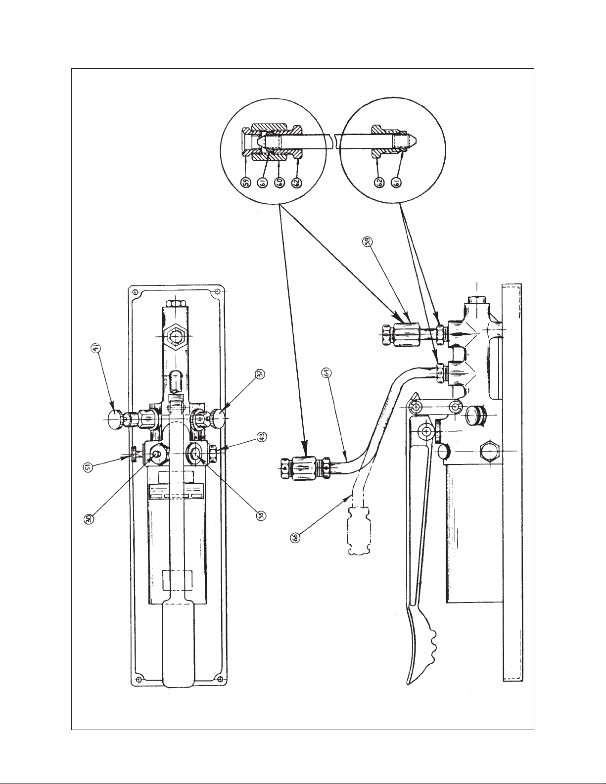
Figure 2-2 Omega Portable Test Pump – Type DWT1327D
Page 14

3.5 Operation DWT1327D
3.5.1 Test Gauge Selection
The portable test pump is used for calibrating instruments
such as pressure gauges, pressure switches or other
pressure devices rated up to 10,000 psi (70,000kPa).
First, select the proper test gauge, depending upon the
pressure range desired. When priming the pump a test
gauge rated to 10,000 psi (70,000kPa) should be used.
3.5.2 Priming The Pump
The offset pipe (64 or 66 Figure 2-2) and straight pipe
extension (58) should already be secured in place and the
reservoir should contain the operating fluid (refer to installation Section 3.4).
Close the release valve (37) by turning it clockwise and
open the air vent by loosening the filler plug (35) a few
turns. The shuttle valve (30) should be pulled outward from
the pump body, the end of the knob approximately even
with the edge of the drip pan. In this position the high volume displacement mode is selected and the pump is selfpriming. Operate the pump handle several times using full
strokes, until you see fluid appear at the top of the straight
pipe extension. Connect the test gauge to it (refer to
Installation Section 3.4 for proper gauge connection).
Operate the pump handle a few more times until fluid is
observed at the end of the offset pipe. Connect the gauge
or other device to be tested to the offset pipe. For purposes of priming, the device must be designed to withstand
the full operating pressure of 10,000 psi (70,000kPa). If a
lower range device must be used, extreme care must be
exercised to avoid overpressuring its pressure element.
Seal the connection to the device by tightening nut adapter
(62) and adapter (60) until the coned end of the pipe is
forced into its inlet. If necessary, rotate the device for viewing by loosening nut adapter (62), set it to the proper position and retighten nut adapter.
Again, operate the pump handle a few more times. After a
few strokes positive pressure will develop and the pump
handle will begin to resist pumping action. Raise the pump
handle to its uppermost travel position. Loosen the bleed
screw (51) a half turn counter clockwise and slowly operate the pump handle through a downward stroke until fluid
flows steadily from the bleed vent. Close the bleed screw
just prior to completing the downward handle motion.
Repeat this action until no air bubbles are observed in the
fluid flow. (Note – the bleed screw must be closed when
the handle is being raised). Push the shuttle valve in
towards the pump body and continue pumping to the
desired test pressure. Open the release valve (37) to vent
the pressure. To check operation pull the shuttle valve outward, close the release valve and operate the pump handle several times. When handle resistance is felt, push the
shuttle valve inward and continue pumping within the
range of the test device.
Entrapped air will prevent the pump from operating in the
high pressure valve position or cause it to achieve only
partial pressure. Repeat the above bleeding procedure as
necessary to assure all air is removed. Once air is
removed the pump will continue to operate without further
attention providing the reservoir level is maintained.
3.5.3 Making The Test
Turn displacement piston handle (41) to mid-position, so
that it may be used for setting an exact pressure on the
gauge. The displacement piston has internal stops which
prevent unscrewing or accidental loss of pressure.
Clockwise rotation of displacement piston will produce an
increase in pressure; counterclockwise will decrease
pressure.
Prior to taking readings, both gauges should be fingertapped lightly at the center of the gauge face, to eliminate
any movement friction. Note the pressure readings on the
test gauge and the gauge under test. If the pressure indicated on the gauge under test is not equal (within the tolerance of the gauge) to the pressures of the master test
gauge, the gauge being tested requires calibration.
CAUTION:
Do not pump handle to pressures greater than the pressure range of the gauges connected to the test pump, as
this may damage the gauges.
3.5.4 To Release Pressure
Open release valve slowly (37), until pressure returns to
zero. Do not loosen any connections until pressure in the
gauge tester has reached zero, as indicated on the test
gauge.
If additional gauges are to be tested, close the release
valve when the pressure reaches zero. This will prevent
complete drainage of oil in the tester back to the reservoir.
Unseal the gauge that has been tested by unscrewing
adapter nut (62) from connector (60) several turns.
Unscrew the gauge from bushing (59) if used, or connector (60), and remove.
Remove the test gauge in the same manner as the gauge
under test.
3.5.5 To Dismantle
To replace test pump in case, remove gauges and both
tube assemblies. Put shipping plugs (57) into pump and
tighten. Close filler plug (35).
3.5.6 Operating Fluids
Standard Test Pump:
Any medium weight oil may be used (including automotive
oils S.A.E 10, 20 or 30) S.A.E. 20-W recommended.
For normal operation it is not necessary to change the
weight of oil for various pressures. A lighter oil may be
used where low pressures are being checked, a heavier oil
where higher pressures are being tested.
The reservoir can be refilled while the test pump is operating under pressure.
3.5.7 Caution
Standard testers designed for oil service may not be used
with water for oxygen service.
3.5.8
Hydraulic service testers should not be filled with water or
any oil other than hydraulic fluid. Serious pump failure may
occur due to O-ring damage.
4.0 FACTORS AFFECTING OPERATION OF
DEADWEIGHT TESTERS
4.1 Deadweight Tester Accuracy
Excellent accuracy is possible using the deadweight tester
through analysis and control of certain factors. If the
tester’s rated accuracy of 1/10th of 1% is adequate, then
Page 15

the nominal pressure (sum of the denominations of the
weights loading the piston) may be assumed to be correct.
The pressure normally developed is determined by this
formula: Deadweight Tester Pressure =
Mass of weights plus piston mass
Effective area of piston and cylinder
P = (M-ph) g
A gs
P=pressure
M=mass of the load on the piston
A=effective area of the piston in sq. inches, or sq. cm
g/gs =ratio of the value (g) of gravity at the point of use to
the standard value of gravity (gs)
P=density of liquid used in test
h=difference in level between gauge being tested, and
the bottom of the piston
The deadweight tester is capable of measuring pressures
to proper corrections after analyzing these factors.
4.2 Gravity, Calibrated Weights
Weights furnished are calibrated at standard gravity of
980.665 gals. If precise accuracy is required, the error
introduced by change of weight due to change in gravity at
the locality should be calculated and included in results.
The mechanism of an Omega Pressure Gauge includes a
Bourdon tube and geared movement, which is unaffected
by variations in gravity. Conversely, the pressure developed by a deadweight tester is proportional to the value of
gravity. Readings of this type pressure gauge will correspond to those of a deadweight tester when the tester is
subjected to standard gravity (gs = 980.665 gals. in the
International System). In southern sections of the United
States, the value of gravity may be several thousandths
less than the standard value, if the latitude (Ø) and the elevation above sea level (a) for an area are known, the
approximate value of (g) in gals. may be calculated from
this formula:
g = 980.632-2.586 COS 2Ø
+.003 COS 4Ø - .000094a
Ø=Latitude (Degrees)
a=Elevation above sea level (ft)
4.3 Effective Measured Area: Chamber
The effective area of the deadweight tester may be determined by the average of the cross sectional area of the
piston and the area of the cylinder bore. This effective area
is affected somewhat by temperature, and by the elastic
distortion of the piston and cylinder when pressure is
being applied. The effective area of a stainless steel piston
and cylinder increases approximately .068% with a 50
degree F (28 degree C) change in temperature. The
pressure will, therefore be less than indicated at high
temperatures.
4.4 Mass, Height, and Buoyancy
The density of air at room temperature and sea level pressure is about 0.0012 grams/c.c., and the mass of the piston assembly and weights under these conditions will be
reduced by about one part in 7,000 or .014%. When the
submerged part of the piston has a uniform cross section,
as with the DWT1305D Deadweight Tester, a buoyancy
correction is not necessary. In other designs, the piston is
sometimes enlarged to provide a stop for its upward motion or for increased strength. If these enlargements are
submerged in liquid, a buoyancy correction is necessary.
4.5 Absence of Friction
By rotating the weights and piston, friction effects are
greatly reduced.
4.6 Head of Transmitting Fluid
Oftentimes, the gauge being tested, or the point at which
pressure is being measured, is not at the same level as
the lower end of the piston. A correction, therefore, should
be made for the pressure distance between these points;
the height is considered positive when the gauge is above
the piston. When oil is used in the gauge tester, the correction will be approximately 0.03 psi (.2 kPa) for each
inch (2.54 cm) difference in level.
4.7 Method of Operation
It is important that the piston be kept floating in mid-position, either spinning or oscillating.
4.8 Levelness
The piston assembly should be vertical to within ±1
degree. A 3 degree tilt to piston axis may cause a .13% of
1% error. The deadweight tester is manufactured and tested to 1/10th of 1% accuracy, to this degree of levelness. A
tilt piston/cylinder axis causes excessive friction, due to
side loading of the piston against the cylinder.
4.9 Cleanliness
The weights have been manufactured and tested to a precision of 0.05%. A buildup of dirt and grease may cause
the weight value to exceed its original tolerance and
produce erroneous pressure readings.
Periodically clean the weights to assure proper
performance.
5.0 MAINTENANCE INSTRUCTION
5.1 General Maintenance
The Deadweight tester and test pump are designed to
serve as precise pressure measuring standards. They are
precision built units and should be cared for in the same
manner as other sensitive laboratory equipment. General
maintenance is limited to cleaning and replacement of Oring packings, which can be done with tools supplied with
the equipment and requires only limited disassembly of
the gauge tester.
The piston supporting the weight platform has been manufactured to very close tolerances. It has an area accuracy
of 1/20th of 1% and a weight accuracy of 1/20th of 1%.
The deadweights have been certified traceable to National
Institute of Standards and Technology with the accuracy of
the finished weights better than 1/20th of 1%. To maintain
deadweight tester accuracy, handle the weights with care
and keep the piston and cylinder in clean condition.
The tester should be flushed with a solvent occasionally,
preferably every six months, so that operating fluid is
always clean. This will prolong component life, and provide
protection against possible sticky action between the piston and cylinder. After cleaning, always lubricate parts
before assembly.
If a deadweight tester is not used for long periods of time,
or if a piston and cylinder assembly is being replaced, the
piston should be removed from the cylinder and coated
with the hydraulic fluid, so that it never operates in a dry
state. When removing or replacing the piston, it should be
rotated back and forth.
Should a piston or cylinder wear excessively, the tester
will leak oil at a high rate, and will not be operable. A new
piston and cylinder assembly should be installed.
Page 16

Piston wear will result from improper or contaminated
lubrication, excessive dirt, or from several years of
continuous use.
5.2 Cleaning
Both the Tester and Test Pump should be cleaned thoroughly whenever the operating fluid is seriously contaminated with dirt, grit, or chemicals. A good practice is to
clean the test unit prior to anticipated periods when the
unit will not be in use.
5.3 To Disassemble for Cleaning
(See Figure 2-1, Figure 2-2 and Figure 5-1)
It is necessary to disassemble only those components
which come in contact with the operating fluid. Complete
disassembly is rarely necessary.
a. Remove pipe extension assembly (58) or piston and
cylinder assembly(67) and (79).
b. Then remove lower or back connection pipe assembly
(64, 66).
5.4 Removing Pump Handle and Piston
a. Remove four retaining rings (8).
b. Slide out two clevis pins (9).
c. Remove clevis (10).
d. Lift hand assembly (4) with piston pin (7) piston (20)
O-ring packing (12, 19) and back-up ring (11)
attached to it, out of piston sleeve (6).
e. Remove back-up washers (18, 11) and O-ring packing
(12, 19).
f. Unscrew piston (20)
g. Remove piston sleeve (6) and O-ring packing (45, 16)
and back-up washers (46, 17)
5.5 Removing Reservoir and Fill Tube
a. Unscrew filler plug (35) from reservoir.
b. Remove gasket (36).
c. Remove reservoir (5) by removing three screws (24).
d. Twist reservoir to free O-ring packing (21) seat.
e. Remove O-ring packing (21) from body (2).
f. Remove fill tube assembly (23) and O-ring packing (27).
g. Remove plug (22).
5.6 Removing Shuttle Valve, Shuttle Valve Plug
and Check Valve
a. Remove set screw (33) and spring (32).
b. Slide shuttle valve piston (31) out of body (2). Operate
back and forth as necessary to dislodge pin (31)
engagement.
c. Remove shuttle pin (31) by pushing it into the shuttle
valve piston cavity using a plastic shaft less than
1
⁄
8
inch (3mm) in diameter.
d. Unscrew shuttle valve plug (43) and remove O-ring
packing (27).
e. Remove check valve spring (14) and check valve (44).
f. Remove O-ring packing (15) from check valve (44).
5.7 Removing Bleeder Valve and Check Valve Assembly
a. Unscrew bleeder valve (51)
b. Unscrew bleed plug (50) and remove O-ring packing
(27).
c. Remove valve spacer (29) check valve spring (14)
and check valve (44).
d. Remove O-ring (15) from check valve (44).
5.8 Removing High Pressure Check Valve
a. Unscrew plug (28) and remove O-ring packing (27).
b. Unscrew adjusting screw (26).
c. Remove guide rod (13), check valve spring (14), and
check valve (44).
d. Remove O-ring packing (15) from check valve (44).
5.9 Removing Release Valve
a. Remove release valve assembly (37) and O-ring
packing (27)
b. Disassemble valve assembly by rotating handle
counter-clockwise until valve stem is free from valve
body.
c. Remove O-ring packing from valve stem.
d. Remove screw (38) and seal (39) by turning counter-
clockwise.
e. Remove O-ring packing (40).
5.10 Removing Displacement Valve
a. Remove displacement valve assembly (41).
b. Remove O-ring packing (27).
c. Remove handle from stem by rotating handle counter-
clockwise. This is not required for normal cleaning.
d. Rotate the stem clockwise (using screwdriver in the
slot at the top of the stem) until it is free from body.
e. Remove nut back-up washers and ring packing from
stem.
5.11 Stem Body from Drip Pan
a. Take out three bolts (25). This is not required for
normal cleaning.
b. Remove body assembly (2) from drip pan (3). This is
not required for normal cleaning.
5.12 Inspection
Visually inspect these parts for wear, damage, chips,
cracks and stripped threads:
Body Assembly Threads
Piston
Piston Sleeve (6)
Displacement Stem and Mating Surface in Body
Back-up Washers
Moving O-ring Packings
Dead Weights
Piston and Cylinder Assembly – DWT1305D
Test Gauges – DWT1327D
Back-up washers must fit snugly into piston sleeve and
into displacement valve body. Then check static (non-moving) packing for pinch marks, tearing or extrusion. Check
all valve seats for scratches and roughness.
Replace all worn or damaged parts. Replace all O-ring
packings at each overhaul. Coat O-ring packings with suitable lubricant before replacing, to prevent sticking and
tearing during assembly and tightening of connections.
5.13 Reassembly
When reassembling, use where possible the wrenches
supplied with the equipment. These wrenches permit
enough leverage to seal all connections. Excessive tightening of parts with tools other than those supplied may
cause distortion and eventual failure of threaded portions
of the tester body assembly casting. When replacing Oring packings, coat them with suitable lubricant to prevent
sticking and tearing during assembly and tightening of
connection.
5.14 To Reassemble
Body assembly on drip pans.
Replace body assembly (2) on drip pan (3) using bolts (25).
5.15 Replacing Displacement Valve
a. Place O-ring packing between back-up washers.
b. Attach back-up washers and O-ring packing to dis
placement valve stem with nut.
c. Thread stem into body from the bottom – use screw
driver in the slot at top of stem.
Page 17

d. Screw stem through body until the back-up washers,
and O-ring packing are fully enclosed in the body.
CAUTION: Do not damage O-ring packing when
threading stem through body.
e. Screw handle onto stem.
f. Replace displacement valve assembly (41) with
O-ring packing (27) in body assembly (2).
5.16 Replacing Release Valve
a. Place O-ring packing (40) in body casting (2) hole.
b. Insert seat (39) into body casting hole.
c. Thread & tighten screw (38) into body casting hole.
CAUTION: Be sure that stem of seat (39) fits into
screw hole.
d. Place O-ring packing on valve stem.
e. Screw handle onto valve stem.
f. Screw valve stem into body until end of stem does not
extend beyond valve body.
CAUTION: Do not damage O-ring packing when
threading valve stem through valve body.
g. Replace O-ring packing (27).
h. Replace release valve assembly (37) in body
assembly (2).
5.17 Replacing High Pressure Check Valve
a. Place O-ring packing (15) on check valve (44).
b. Slide check valve (44), check valve spring (14), and
guide rod (13) into body assembly (2).
c. Replace adjusting screw (26) and screw it in until it
stops.
d. Then turn (26) back two complete revolutions.
e. Replace plug (28) with O-ring packing (27) in body
assembly (2).
5.18 Replacing Bleeder Valve and Check
Valve Assembly
a. Replace O-ring packing (15) on check valve (44).
b. Slide check valve (44), check valve spring (14) and
valve space (29) into body assembly (2).
c. Replace bleed plug (50) with O-ring packing (27) into
body assembly (2).
5.19 Replacing Shuttle Valve, Shuttle Valve Plug and
Check Valve
a. Insert shuttle valve piston (3) into body (2).
b. Slide shuttle pin (31) into 1/8 inch (3mm) diameter
opening adjacent to fill tube (23) port. Apply slight
inserting pressure to shuttle pin (31) with plastic shaft
and operating shuttle valve (30) to insure proper
pin engagement.
c. Replace spring (32) directly behind shuttle pin (31)
and secure with set screw (33). Set screw must be
recessed by .050 inch (12mm) minimum.
d. Replace O-ring packing (15) on check valve (44).
e. Slide check valve (44) and check valve spring (14)
into body assembly (2).
5.20 Replacing Reservoir and Fill Tube
a. Replace plug (22).
b. Replace fill tube assembly (21) and O-ring packing (27).
c. Replace O-ring packing (21) on body assembly (2).
d. Replace reservoir (5) using three screws (24).
e. Replace filler plug (35) and gasket (36) on body.
5.21 Replacing Pump Handle and Piston
a. Replace piston sleeve (6) and O-ring packing (45, 16)
and back-up washers (46, 17) in body assembly (2).
b. Place O-ring packing (12, 19) between back-up
washers (18, 11)
c. Attach back-up washers (18,11) and O-ring packing
(12, 19) to piston (20).
d. Lubricate piston and sleeve.
e. Attach assembled piston to handle assembly (4).
CAUTION: Do not damage O-ring packing (12, 19)
when sliding assembled piston into piston sleeve (6).
f. Attach clevis (10) to handle assembly and to body
assembly (2), using clevis pins (9) and retaining
rings (8).
5.22 Replacing Piston/Cylinder Assemblies
The piston/cylinder assembly for a deadweight tester
should be replaced when excessive wear is detected on
any component part. Worn piston assemblies are usually
noted by:
1. Excessive leakage of operating fluid through piston
assembly when under pressure.
2. Seizure of piston in cylinder.
3. Damaged piston plate, damaged cylinder threads, or
damage to any component part that results in inferior
performance, or malfunctioning of the unit.
The piston/cylinder assembly is available as a unit only.
This assures the user of maximum accuracy in his Omega
Deadweight Tester and maintains certified traceability to
the National Institute of Standards and Technology.
Page 18

5.4 Troubleshooting Chart
Corrective
Symptom Case Action
Pressure does
not build up when
Insufficient fluid
level in reservoir.
Add fluid.
pumping handle.
Piston O-rings
worn or ruptured.
Inspect O-rings
and replace as
necessary. If
O-rings are new,
verify their fluid
compatibility.
Bleed port check
valve or shuttle
check valve
Inspect O-rings
and replace as
necessary.
inoperative.
Fill tube assembly
and filter plugged.
Remove and clean
fill tube assembly.
Refill reservoir
with clean fluid.
Shuttle valve
pushed in for
small fluid dis-
Pull shuttle valve
outward from
body.
placement when
large fluid displacement is
required.
High pressure
does not increase
when pumping
handle while
shuttle valve is
pushed in.
Air trapped in
pump piston.
Rapid pump handle strokes which
lessen fluid flow
through the pump
Reprime pump.
Operate pump
handle with
smooth moderate
action.
piston.
Pressure builds up
when pumping
handle, but
decreases when
pumping is
stopped.
Leakage at outlet
or gauge connections(s).
High pressure
check valve O-ring
worn or ruptured.
Defective pressure
release valve.
Inspect connec-
tions and tighten
as necessary.
Inspect O-ring and
replace as neces-
sary.
Hand tighten
release valve.
Inspect release
valve seating sur-
faces. Replace as
necessary.
Remove release
valve seat and
inspect O-ring
underneath.
Replace as
necessary.
Corrective
Symptom Case Action
Pump handle rises
after pumping.
Piston plate (with
deadweights)
drops rapidly.*
Unable to hold
High pressure
check valve O-ring
worn or ruptured.
Worn piston and
cylinder assembly.
Inspect O-ring
and replace as
necessary.
Use a heavy oil
temporarily.
Replace piston &
cylinder.
constant pressure.
Stacked deadweights wobble
when spinning piston plate.*
Damaged deadweights.
Check deadweights for visible
damage (bends,
dents, nicks, etc.)
and alignment.
Piston plate
assembly will not
spin.*
Too heavy an oil
grade being used.
Flush & fill unit
with proper grade
of oil (SAE 20 or
SAE 10).
Replace piston &
cylinder assembly.
Disassemble and
flush complete test
unit with kerosene
or alcohol.
Reassemble unit.
*These symptoms apply only to the DWT1305D Deadweight
Testers.
Page 19

5.0 RETURN SHIPPING INFORMATION
Company Name
Phone Number
FAX Number – – – – – – – – – – – – – – – – – – – – – – – – – – – – – – – – – –
Person to Contact
Address
email Address
Model
Serial Number
Symptoms
– – – – – – – – – – – – – – – – – – – – – – – – – – – – – – – – – – – – – –
– – – – – – – – – – – – – – – – – – – – – – – – – – – – – – – – – – – – – – – – – – – –
– – – – – – – – – – – – – – – – – – – – – – – – – – – – – – – – – – – – – – – – – – – –
– – – – – – – – – – – – – – – – – – – – – – – – – – – – – – – – – – – – – – – – – – – –
– – – – – – – – – – – – – – – – – – – – – – – – – – – – – – – – – – – – – – – –
– – – – – – – – – – – – – – – – – – – – – – – – – – – – – – – – – – – – – – – – – – – –
– – – – – – – – – – – – – – – – – – – – – – – – – – – – – – – – – – – – – – – – – – – –
– – – – – – – – – – – – – – – – – – – – – – – – – – – – – – – –
– – – – – – – – – – – – – – – – – – – – – – – – – – – – – – – – –
– – – – – – – – – – – – – – – – – – – – – – – – – – – – – –
– – – – – – – – – – – – – – – – – – – – – – – – – – – – – – – – –
– – – – – – – – – – – – – – – – – – – – – – – – – – – – – – – – –
– – – – – – – – – – – – – – – – – – – – – – – – – – – – – – – – – – – –
Page 20
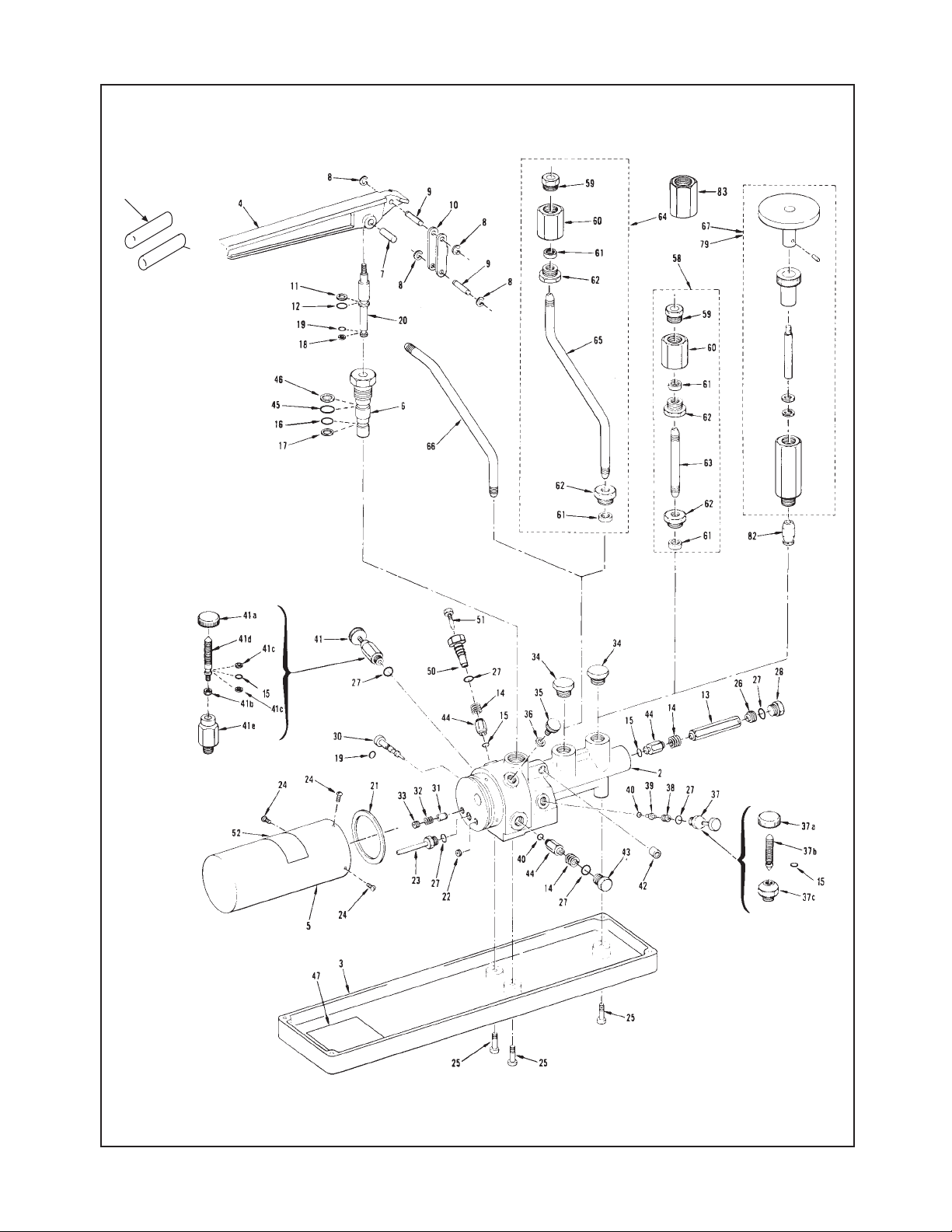
4A
Page 21
REPLACEMENT PARTS
PORTABLE DEADWEIGHT TESTER – TYPE DWT1305D
PORTABLE TEST PUMP – TYPE DWT1327D
Qty.
Item Per
No. Asmy. Part No. Description
21603D001-01 Body Only, Pump
3 1 LB285A Drip Pan
4 1 603X010-01 Handle
4A 1 636X003-01 Grip
5 1 LF341A Reservoir
6 1 610C001-01 Sleeve, Piston
71 LA810A Pin, Piston
84 BA221L Retaining Ring
9 2 LB810A Pin, Clevis
10 1 LD278A Clevis
11 1 607A002-02 Backup Ring
12 1 607A001-02 “O” Ring
13 1 LB802 Guide Rod
14 3 LA242 Spring, Valve
15 4 SSSS882 “O” Ring
16 1 607A001-03 “O” Ring
17 1 607A002-03 Backup Ring
18 1 607A002-01 Backup Ring
19 2 607A001-01 “O” Ring
20 1 614C001-01 Piston, Dual Diameter
21 1 BA122R “O” Ring
22 1 604A003-01 Plug
23 1 615B001-01 Fill Tube Assembly
24 3 605A002-06 Screw, Round Head
25 3 SAFH37 Screw, Allen Socket Head
26 1 LK260A Adjusting Screw
27 6 BA122V “O” Ring
28 1 LK696A Plug
29 1—Spacer, Valve, Use Item 50
30 1 614B002-01 Piston, Shuttle
31 1 609A001-01 Pin, Shuttle
32 1 612B001-01 Spring, Shuttle Pin
33 1 605A001-01 Set Screw
34 2 LP696 Plug, Shipping
35 1 604B002-01 Plug, Fill
36 1 607A003-01 Gasket, Fill Plug
37 1 LAH292C Valve Assembly, Release
37a 1 328A105-01 Knob
37b 1 LD870B Valve Stem
37c 1 LAH292A Body, Release Valve
38 1 LD83A Scew, Seat
39 1 LD911A Seat
40 2 BA122U “O” Ring
41 1 LAG292C Valve Assembly, Displacement
41a 1 328A105-02 Knob
41 b 1 LE83 Nut
41c 2 LB122 Backup Washer
41d 1 LB870A Stem
41e 1 LAG292A Body, Displacement Valve
42 1 LA521A Sleeve
43 1 604B001-01 Plug, Shuttle Valve
44 3 609B003-01 Check Valve
45 1 BA122W “O” Ring
46 1 607A002-04 Backup Ring
50 1 604B004-01 Plug, Bleed
51 1 609B004-01 Bleed Valve
52 1 618B001 Nameplate
58 1 LK227 Pipe Extension Assembly
Qty.
Item Per
No. Asmy. Part No. Description
59 2 LD227A Bushing
60 2 LN141 Adapter
61 4 LD186 Collar
62 4 LD117 Nut, Adapter
63 1 LH227A Extension Pipe
64 1 LJ227 Lower Connection Pipe Assembly
65 1 LF227A Lower Connection Pipe
66 1 LG227A Back Connection Pipe
67 — Low Pressure Piston Assembly
1 LM869 psig
1 LM869D kg/cm
1 LM869E bar & Pascal
79 – High Pressure Piston Assembly
1 LN869 psig
1 LN869D kg/cm
1 LN869E bar & Pascal
82 1 LF217 Disc Seat
83 1 LM141 Adapter
1 617C002-01 “O” Ring Kit, Oil
1 617A003-01 Overhaul Kit, Oil (see note 1)
1 LH244A Wrench (1 x 11⁄8)
1 LH244 Wrench (7⁄8 x 1)
1 LG244 Wrench (
*Piston and bushing can only be replaced as a complete assembly, the
part number for this assembly is for:
DWT1305DH – part no. 617B001-01
DWT1305DH – part no. 617B001-02
2
2
5
⁄8)
PARTS IN THE SECTION BELOW ARE USED IN
HYDRAULIC SERVICE UNITS. THESE UNITS CAN BE
RECOGNIZED BY THE INCLUSION OF THE LETTER “H”
IN THE MODEL DESIGNATION.
12 1 607A004-02 “O” Ring
15 4 BA122H “O” Ring
16 1 607A004-03 “O” Ring
19 2 607A004-01 “O” Ring
21 1 BA122E “O” Ring
27 6 BA122D “O” Ring
37 1 LAH292D Valve Assembly, Release
40 2 BA122G “O” Ring
41 1 LAG292D Valve Assembly, Displacement
45 1 BA122F “O” Ring
1 LGG236A Nameplate, Hydraulic
1 617C002-02 “O” Ring Kit, Hydraulic
1 617A003-02 Overhaul Kit, Hydraulic (see note 1)
1 Overhaul kit includes all O-rings required to overhaul pump as
well as piston and bushing assembly.
Page 22

Page 23

WARRANTY/DISCLAIMER
MADE IN
OMEGA warrants this unit to be free of defects in materials and workmanship and to give satisfactory
service for a period of 13 months from date of purchase. OMEGA’s Warranty adds an additional one (1)
month grace period to the normal one (1) year product warranty to cover handling and shipping
time. This ensures that OMEGA’s customers receive maximum coverage on each product. If the unit
should malfunction, it must be returned to the factory for evaluation. OMEGA’s Customer Service
Department will issue an Authorized Return (AR) number immediately upon phone or written request.
Upon examination by OMEGA, if the unit is found to be defective it will be repaired or replaced at no
charge. However, this WARRANTY is VOID, if the unit shows evidence of being damaged as a result of
excessive corrosion; or current, heat, moisture or vibration; improper specification; misapplication; misuse
or other operating conditions outside of OMEGA’s control. Components which wear or which are damaged
by misuse are not warranted. These include contact points, fuses, and triacs.
OMEGA is pleased to offer suggestions on the use of its various products. Nevertheless, OMEGA
only warrants that the parts manufactured by it will be as specified and free of defects.
OMEGA MAKES NO OTHER WARRANTIES OR REPRESENTATIONS OF ANY KIND WHATSOEVER, EXPRESS OR IMPLIED, EXCEPT THAT OF TITLE, AND ALL IMPLIED WARRANTIES
INCLUDING ANY WARRANTY OF MERCHANTABILITY AND FITNESS FOR A PARTICULAR PURPOSE
ARE HEREBY DISCLAIMED.
LIMITATION OF LIABILITY: The remedies of purchaser set forth herein are exclusive and the total
liability of OMEGA with respect to this order, whether based on contract, warranty, negligence,
indemnification, strict liability or otherwise, shall not exceed the purchase price of the component
upon which liability is based. In no event shall OMEGA be liable for consequential, incidental or
special damages.
CONDITIONS: Equipment sold by OMEGA is not intended to be used, nor shall it be used: (1) as a “Basic
Component” under 10 CFR 21 (NRC), used in or with any nuclear installation or activity; or (2) in medical
applications or used on humans. Should any Product(s) be used in or with any nuclear installation or
activity, medical application, used on humans, or misused in any way, OMEGA assumes no responsibility
as set forth in our basic WARRANTY/ DISCLAIMER language, and additionally, purchaser will indemnify
OMEGA and hold OMEGA harmless from any liability or damage whatsoever arising out of the use of the
Product(s) in such a manner.
RETURN REQUESTS/INQUIRIES
Direct all warranty and repair requests/inquiries to the OMEGA ENGINEERING Customer Service
Department. BEFORE RETURNING ANY PRODUCT(S) TO OMEGA, PURCHASER MUST OBTAIN AN
AUTHORIZED RETURN (AR) NUMBER FROM OMEGA’S CUSTOMER SERVICE DEPARTMENT (IN ORDER
TO AVOID PROCESSING DELAYS). The assigned AR number should then be marked on the outside of
the return package and on any correspondence.
FOR WARRANTY
following information available BEFORE
contacting OMEGA:
1. Purchase Order number under which the product
was PURCHASED,
2. Model and serial number of the product under
warranty, and
3. Repair instructions and/or specific problems
relative to the product.
RETURNS, please have the
FOR NON-WARRANTY REPAIRS OR CALIBRATION,
consult OMEGA for current repair charges. Have
the following information available BEFORE contacting OMEGA:
1. P.O. number to cover the COST of the
repair/recalibration,
2. Model and serial number of the product, and
3. Repair instructions and/or specific problems
relative to the product.
OMEGA’s policy is to make running changes, not model changes, whenever an improvement is possible. This affords our
customers the latest in technology and engineering.
OMEGA is a registered trademark of OMEGA ENGINEERING, INC.
© Copyright 1996 OMEGA ENGINEERING, INC. All rights reserved. This document may not be copied, photocopied,
reproduced, translated, or reduced to any electronic medium or machine-readable form, in whole or in part, without the
prior written consent of OMEGA ENGINEERING, INC.
Page 24

Where Do I Find Everything I Need for
Process Measurement and Control?
OMEGA…Of Course!
TEMPERATURE
˛
Thermocouple, RTD & Thermistor Probes, Connectors, Panels & Assemblies
˛
Wire: Thermocouple, RTD & Thermistor
˛
Calibrators & Ice Point References
˛
Recorders, Controllers & Process Monitors
˛
Infrared Pyrometers
PRESSURE, STRAIN AND FORCE
˛
Transducers & Strain Gages
˛
Load Cells & Pressure Gages
˛
Displacement Transducers
˛
Instrumentation & Accessories
FLOW/LEVEL
˛
Rotameters, Gas Mass Flowmeters & Flow Computers
˛
Air Velocity Indicators
˛
Turbine/Paddlewheel Systems
˛
Totalizers & Batch Controllers
pH/CONDUCTIVITY
˛
pH Electrodes, Testers & Accessories
˛
Benchtop/Laboratory Meters
˛
Controllers, Calibrators, Simulators & Pumps
˛
Industrial pH & Conductivity Equipment
DATA ACQUISITION
˛
Data Acquisition & Engineering Software
˛
Communications-Based Acquisition Systems
˛
Plug-in Cards for Apple, IBM & Compatibles
˛
Datalogging Systems
˛
Recorders, Printers & Plotters
HEATERS
˛
Heating Cable
˛
Cartridge & Strip Heaters
˛
Immersion & Band Heaters
˛
Flexible Heaters
˛
Laboratory Heaters
ENVIRONMENTAL
MONITORING AND CONTROL
˛
Metering & Control Instrumentation
˛
Refractometers
˛
Pumps & Tubing
˛
Air, Soil & Water Monitors
˛
Industrial Water & Wastewater Treatment
˛
pH, Conductivity & Dissolved Oxygen Instruments
M0627/0813
 Loading...