

Page 1
Product specification
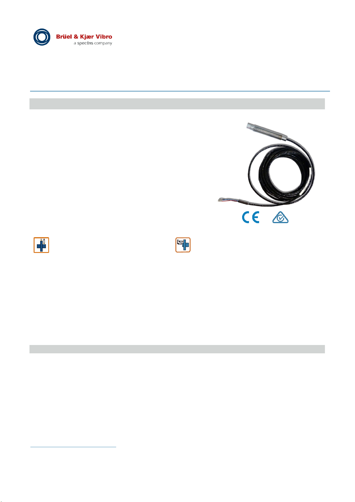
Displacement Transmitter Series DT-120
Non-contacting integrated displacement transmitter
Features
• Maximum linear range 2 mm (0.5 - 2.5 mm from target)
• Loop-powered
• Driver electronics are built into the transmitter housing
• Temperature range: -40 °C ... +105 °C.
• Dynamic signal output for easy installation (raw signal)
• Cost-saving installation – no separate driver needed
Measurement
Radial shaft vibration
DT-12x.RV
1
Axial shaft position
DT-12x.AP
1
Product description
The integrated DT-120 series displacement transmitters are based on the non-contacting eddy current
measurement principle, which has proven itself in the machine monitoring sector for several decades. It allows
the distance between the tip of the displacement transmitter and an electrically conductive surface to be
measured. The integrated electronics measure the axial shaft position or the radial shaft vibration from the
displacement signal, depending on the model being used. The measurement result is outputted to a
subsequent controller, via the loop-powered interface, as a 4 - 20 mA signal. An additional dynamic output
provides a diagnostic signal for simple system setup or signal analysis. Our series DT-120 eddy current
displacement transmitters are distinguished by their innovative design. All of the measuring electronics and the
loop-powered interface are integrated in the transmitter's housing. This considerably simplifies the installation
of these systems as compared to those with external driver electronics. The displacement transmitter is
available in both forward and reverse mount versions.
Contents
Non-contacting integrated displacement transmitter 1
Features 1
Measurement 1
Product description 1
Technical data 2
Notes on operation 4
Clearances and minimum distances 5
Mechanical versions 6
Displacement transmitter order code 8
Accessories 9
Approval / Declaration of Conformity 10
1
"x" option defines the housing version
Page 1 of 12
We reserve the right to make technical changes!
█ © Brüel & Kjaer Vibro ● September 2019 ● BPS0157-EN-13
Page 2

EN
Technical data
The following performance data applies under the following standard conditions, unless stated otherwise:
+18 °C to +27 °C ambient temperature, +24 VDC supply voltage, 250 Ω loop resistance, dynamic output not
connected, B&K Vibro original reference material, Material-No. 1.7225 (42CrMo4) as per EN10083-3 and as
per AISI/SAE 4140, +6 V gap voltage; all components are at operating temperature (approx. 1h).
Measurement type:
Radial Vibration (RV) Radial shaft vibration in [μm peak-to-peak]
Axial Position (AP) Axial shaft position in [μm]
Measuring principle Eddy current method
Functional characteristics:
Loop output:
Output signal 4 - 20 mA, live-zero
Signaling (range overshoot, error) As per NAMUR Recommendation 43
System error < 3,6 mA
Full scale range overshoot (RV + AP) 20,5 mA
Full scale range undershoot (AP only) 3,8 mA
Loop
Nominal 250 Ω
Maximal depends on the supply voltage V
(see Fig. 1)
Accuracy
0 °C … + 45 °C ±0,2 % from full scale (FS)
Overall operating temperature range ±0,5 % (FS)
Installation Position Transmitter (GAP):
Transmitter must be gapped from target
(shaft) between +2V to +18V
equal to linear range > 0.5mm to < 2.5mm
Radial shaft vibration (DT-12x.RV):
Full scale range, nominal [µm peak-peak] 0 – 100 | 0 – 250 | 0 – 600
Loop sensitivity, nominal [µm p-p/mA] 6,25 | 15,63 | 37,5
Full scale range, nominal [mils peak-peak] 0 – 4 | 0 – 10 | 0 – 24
Loop sensitivity, nominal [mils p-p/mA] 0,25 | 0,625 | 1,5
Sensitivity accuracy
in the temperature range of:
0 °C ... +45 °C ±5 %
Overall operating temperature range ±10 %
Loop frequency range 5 Hz … 4 kHz
Loop refresh time 15 ms
Axial shaft position (DT-12x.AP):
Full scale range, nominal [mm] 0 – 1,2 | 0 – 1,5
Loop sensitivity, nominal [µm/mA] 75,0 | 93,8
Full scale range, nominal [mils] 0 – 50 | 0 – 60
Loop sensitivity, nominal [mils/mA] 3,125 | 3,75
Accuracy
Deviation (DSL) from best fit straight line
with nominal loop sensitivity
in the temperature range of:
0 °C ... +45 °C ±25 µm
Overall operating temperature range ±75 µm
Loop frequency range DC … 0,8 Hz
Loop refresh time 100 ms
resistance
Loop
Page 2 of 12
We reserve the right to make technical changes!
█ © Brüel & Kjaer Vibro ● September 2019 ● BPS0157-EN-13
Page 3

© Brüel & Kjaer Vibro │ Product specification
Transmitter Series DT-120
Technical data
EN
Dynamic output:
Application Connection of a potential-free portable measuring
instrument for system setup or signal analysis;
not designed for continuous operation; limited cable
length
Cable length max. 15 m
(including transmitter integrated cable length)
Cable capacity max. 150 pF/m
Output resistance 8 kΩ DC (load > 500 kΩ, 1,5 nF)
Output signal Depends on the loop voltage and loop resistance,
see Table 1
Sensitivity, nominal +8 mV/µm
Frequency range DC … 8 kHz (-3 dB output signal damping)
Accuracy
0 °C … +45 °C ±5 %
Overall operating temperature range ±10 %
Behaviour in the event of maximum linear range Output remains active; max. output voltage
overshoot or system error depends on loop voltage; short voltage dips at the
start of signaling of a measuring range overshoot is
possible
Design short circuit proof and miswiring proof
Electrical properties:
Operating voltage +24 VDC (+12 VDC ... +32 VDC)
Current consumption max. 21 mA
Mechanical properties:
Cable:
Design 4 wire
Cable sheath and colouring PTFE, black
Wire assignments:
Loop white (+), black (-)
Dynamic output red (+), blue (-)
Diameter Ø 2,9 mm (±0,15 mm)
Wire cross-section 0,16 mm²
Length 5 m or 10 m
Transmitter tip:
Material Ceramic
Tip diameter Ø 7,2 mm (± 0,1 mm)
Transmitter sleeve:
Material Stainless steel (Material-No.1.4404
X2CrNiMo17-12-2 nach EN10088-3)
Recommended tightening torque 5 Nm
Transmitter weight (5m version): approx. 150 g
Environment:
Pressure tightness:
Transmitter tip 25 bar
Transmitter with corrugated tube protection 25 bar (valid only for DT-122)
Temperature range:
Operating temperature range -40 °C ... +105 °C
Storage temperature range -55 °C ... +125 °C
IP protection degree according to EN 60529 IP68, IP69
© Brüel & Kjaer Vibro ● September 2019 ● BPS0157-EN-13 ● █ Page 3 of 12
We reserve the right to make technical changes!
Page 4
EN
20 V
1)
24 V
11.4 V
28 V
15.4 V
1250
Loop
Notes on operation
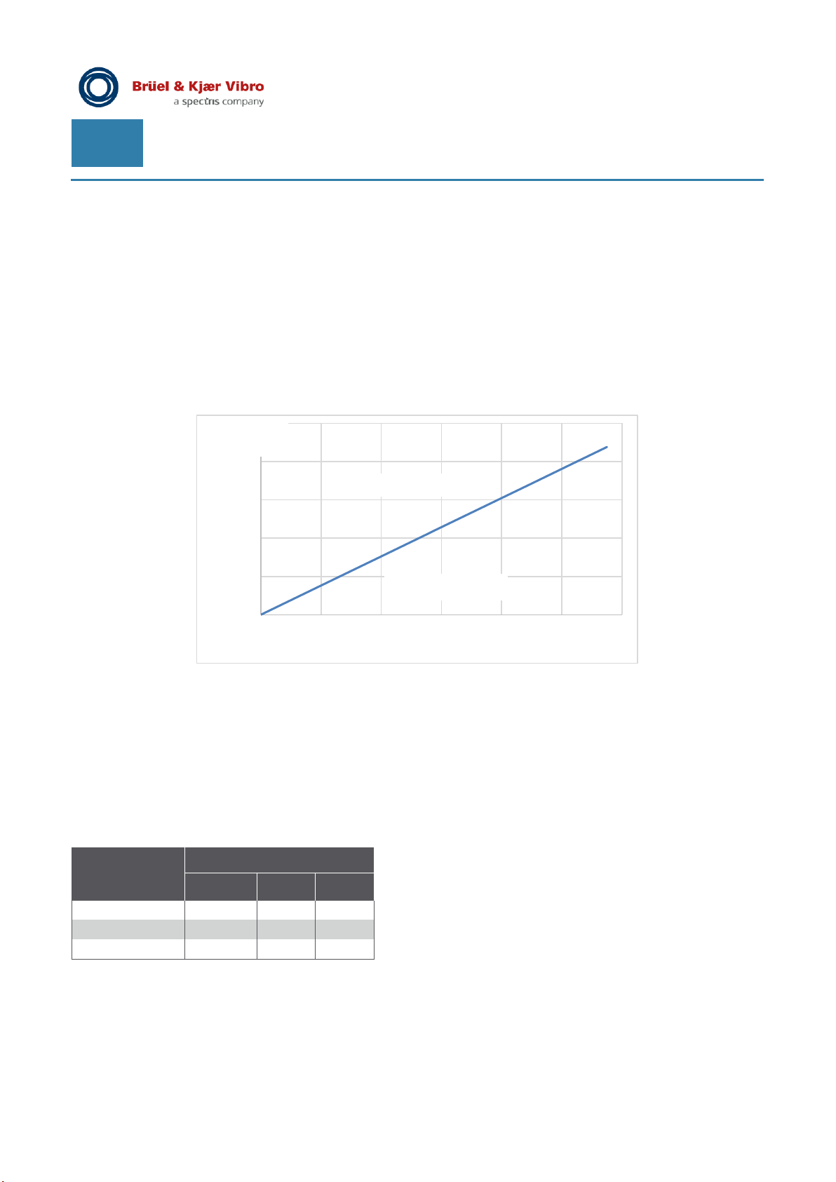
Maximum loop resistance R
Loop-max
The total loop resistance consists of the measuring resistance of the supplying electronics and the effective
cable resistance:
Loop
= R
• R
The maximum permissible loop resistance for a given voltage supply V
Meas
+ R
Cable
is calculated using the following
Loop
formula:
• R
Loop-max
= 47 x (V
- 12) [Ohm]
Loop
The diagram shows the relationship between the supply voltage V
and the maximum permitted loop
Loop
resistance.
R-Loop-max
(Ohm)
1000
750
500
250
No operation
Operating area
0
12 16 20 24 28 32 36
Supply voltage V
Figure 1) Dependency of the supply voltage on the maximum loop resistance
(Volt)
Range of the maximum dynamic output signal
The output of the diagnostic signal via the dynamic output DYN_OUT requires a sufficiently high supply voltage
for a given loop resistance R
V
Loop
DYN_OUT < V
Table 1) shows the relationships between the maximum outputted DYN_OUT and R
R
V
Loop
Table 1) DYN_OUT
1) No operation possible
2) Voltages higher than 21.4 V cannot be outputted.
100 Ω 250 Ω 500 Ω
15.4 V 12.4 V
19.4 V 16.4 V
21.4 V2) 20.4 V
(R
Loop
, V
Max
In case of insufficient supply voltage V
Page 4 of 12
We reserve the right to make technical changes!
█ © Brüel & Kjaer Vibro ● September 2019 ● BPS0157-EN-13
Loop
Loop
Loop
Loop
:
– I
Loop
x R
– 2.6 V
Loop
and V
Loop
)
, the DYN_OUT dynamic output signal range might be limited.
Loop
Loop
Page 5
© Brüel & Kjaer Vibro │ Product specification
Distance to the shaft
Required minimum shaft
Transmitters installed
Transmitter Series DT-120
Clearances and minimum distances
EN
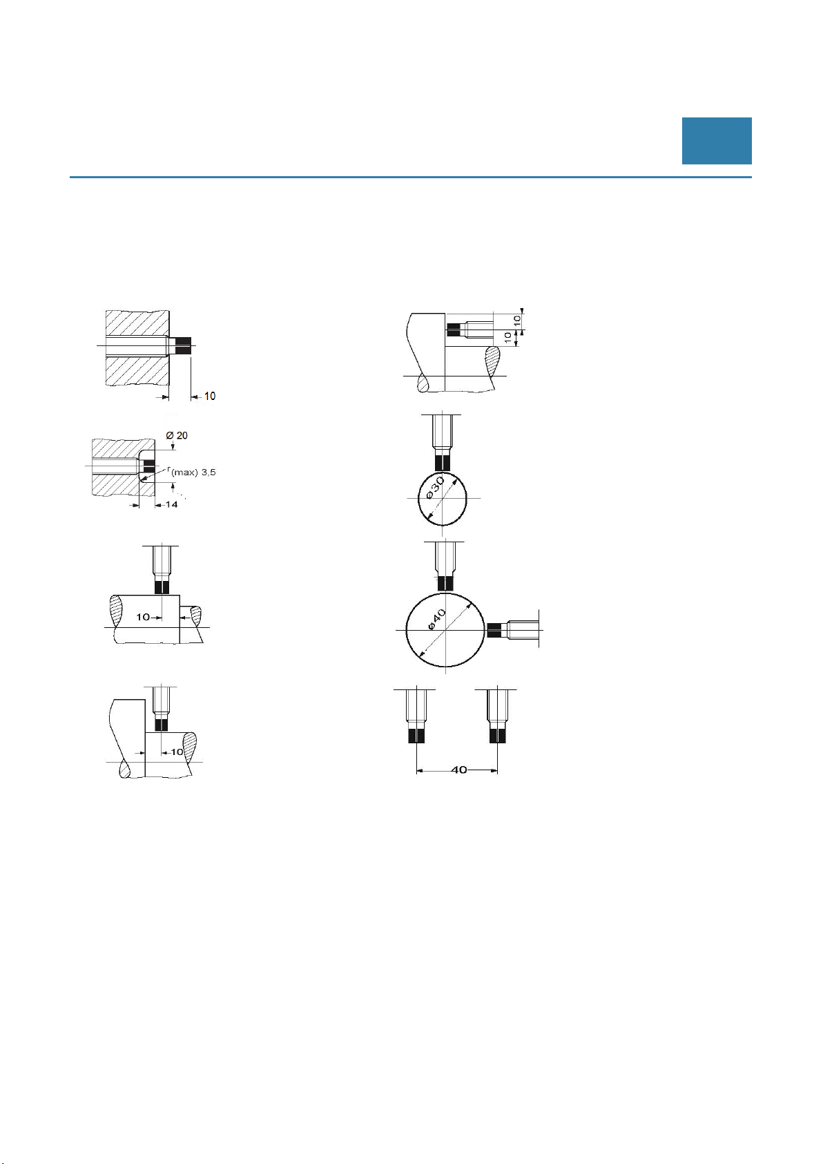
Clearances and minimum distances
The clearances and minimum distances specified below must be observed when installing the transmitter.
Protruding
transmitter tip
shoulder Transmitter parallel
to electrically conductive
material
Flush transmitter tip
Distance to a shaft
end
Distance to the
shaft shoulder
Transmitter parallel
to electrically
conductive
material
diameter for one transmitter
Required minimum
shaft diameter with
two transmitters
in parallel
© Brüel & Kjaer Vibro ● September 2019 ● BPS0157-EN-13 ● █ Page 5 of 12
We reserve the right to make technical changes!
Page 6
EN
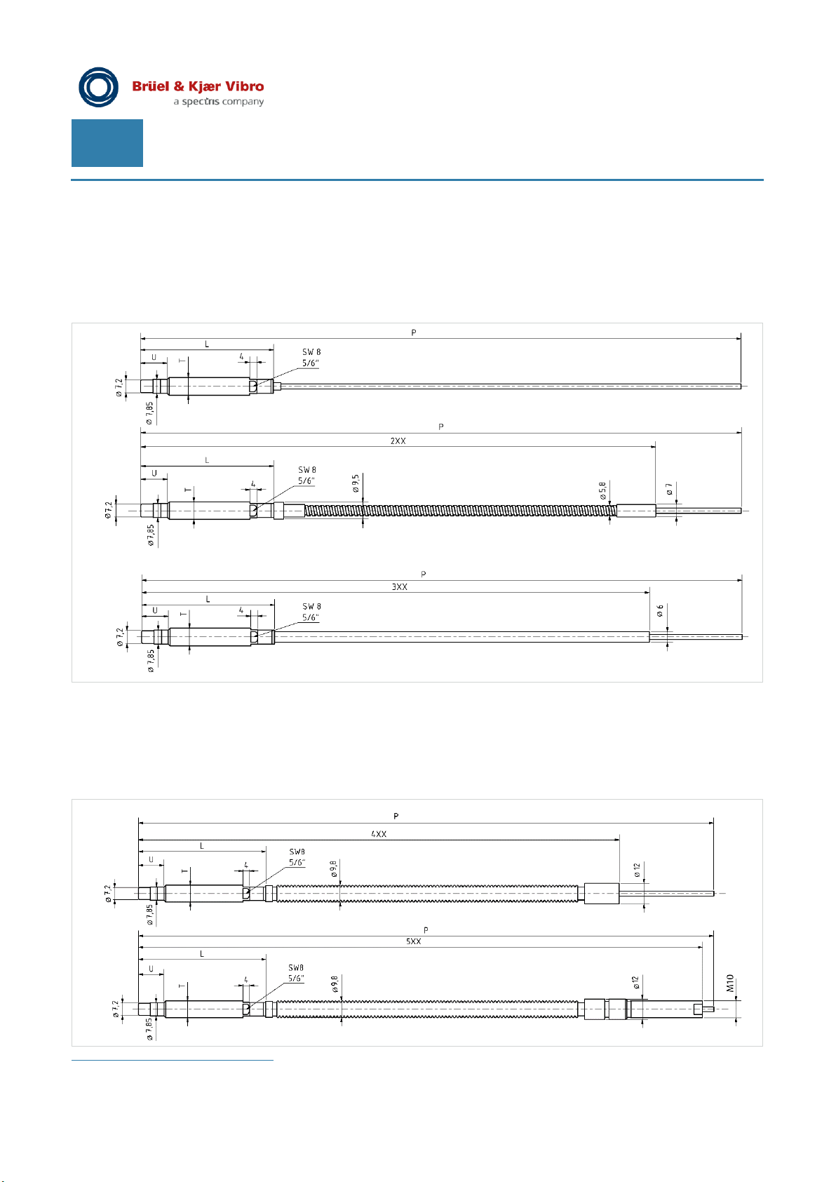
Mechanical versions2
Displacement transmitter with continuous thread DT-121...
• Without cable protection: DT-121.MT/MR/TT/LLL/UUU/PPP/000/R (upper image)
• With steel protective conduit, Length XX: DT-121.MT/MR/TT/LLL/UUU/PPP/2XX/R (centre image)
• With PTFE protective conduit, Length XX: DT-121.MT/MR/TT/LLL/UUU/PPP/3XX/R (lower image)
Displacement transmitter with continuous thread and pressure-tight corrugated tube DT-122…
• With corrugated tube protection design A, Length XX: DT-122.MT/MR/TT/LLL/UUU/PPP/4XX/R
(upper image)
• With corrugated tube protection design B, Length XX:
(lower image)
2
Comments about drawings: all information is in [mm]
DT-122.MT/MR/TT/LLL/UUU/PPP/5XX/R
Page 6 of 12
We reserve the right to make technical changes!
█ © Brüel & Kjaer Vibro ● September 2019 ● BPS0157-EN-13
Page 7
© Brüel & Kjaer Vibro │ Product specification
Transmitter Series DT-120
EN
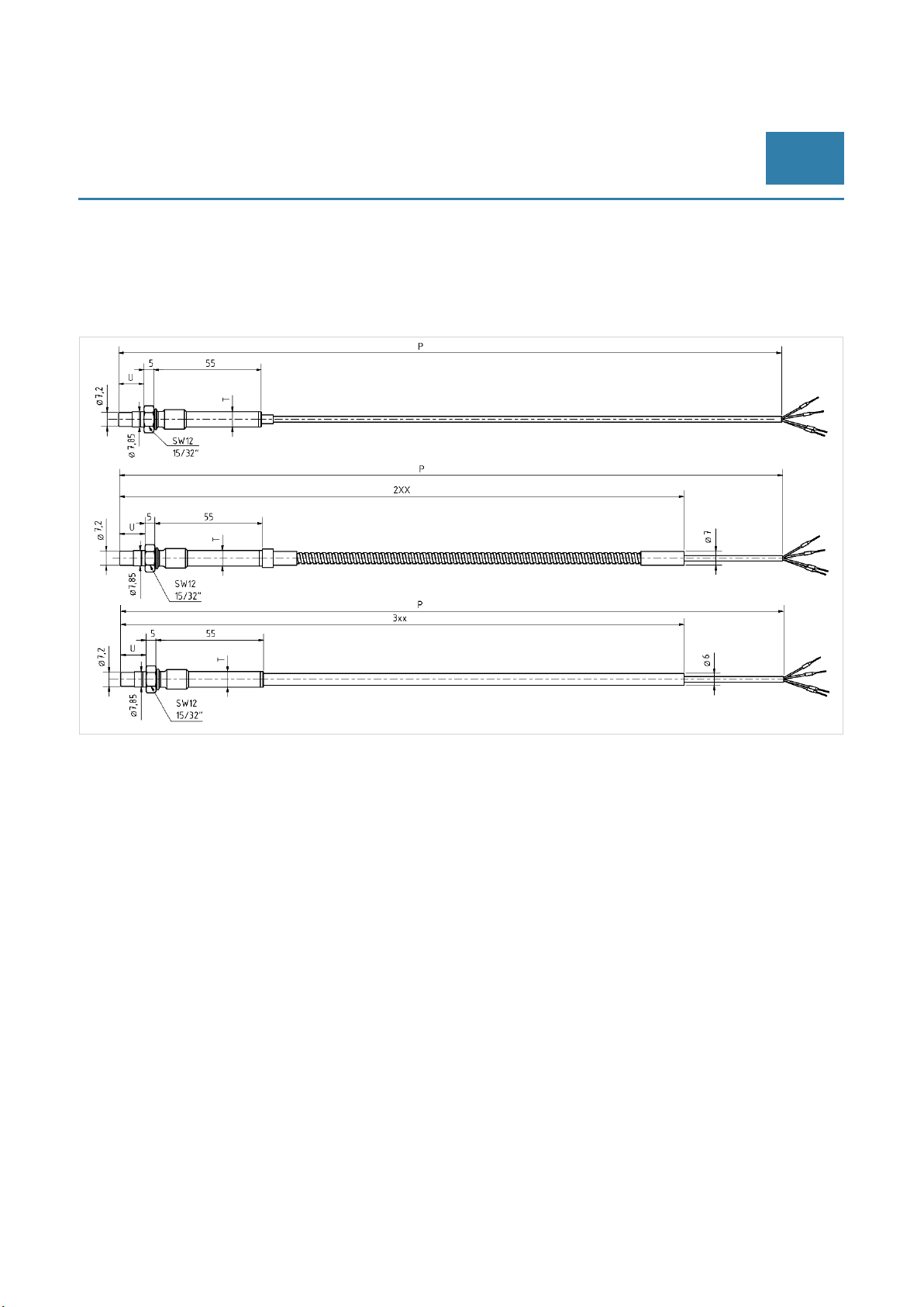
Displacement transmitter for reverse mount DT-123...
• Without cable protection DT-123.MT/MR/TT/073/013/PPP/000/R (upper image)
• With steel protective conduit, Length XX: DT-123.MT/MR/TT/073/013/PPP/2XX/R (centre image)
• With PTFE protective conduit, Length XX: DT-123.MT/MR/TT/073/013/PPP/3XX/R (lower image)
© Brüel & Kjaer Vibro ● September 2019 ● BPS0157-EN-13 ● █ Page 7 of 12
We reserve the right to make technical changes!
Page 8
EN
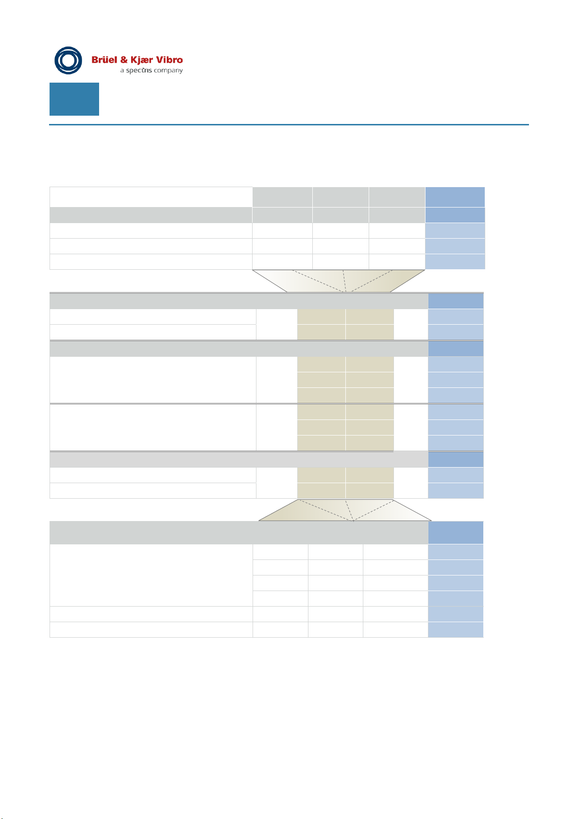
“D” transmitter type
D
Continuous thread with corrugated tube
2
Reverse mount
3
“MT” Measurment type
.MT
RV
AP
“MR” Measuring Range
/ MR
0
1
2
5
6
7
“T” Thread
/ TT
10
3/8 – 24 UNF-2A
62
“L” Length of the transmitter body [mm]
Increment 005 = 5 mm
Displacement transmitter order code
DT–12D.MT / MR / TT / LLL / UUU / PPP / CXX / R
DT-121 DT-122 DT-123 DT-12…
Continuous thread
Radial shaft vibration (RV)
Axial shaft position (AP)
RV [µm] / AP [mm]
RV [mils] / AP [mils]
M10 x 1
250 1.5
600
10 60
24
1
100 1.2
4 50
Preferred lengths
Fixed length 73 073
Other lengths min - max 75 - 250 75 - 250 xxx
Page 8 of 12
We reserve the right to make technical changes!
█ © Brüel & Kjaer Vibro ● September 2019 ● BPS0157-EN-13
/ LLL
75 75 075
90 90 090
105 105 105
125 125 125
Page 9

© Brüel & Kjaer Vibro │ Product specification
Preferred length
15
15 015
Fixed length
13
013
Other lengths min - max
20 - 210
20 - 210
XXX
/ R
Transmitter Series DT-120
“U” unthreaded section [mm]
U
= L – 40 mm ; increment ‘005’ = 5 mm (as from “U” = 15 mm)
max
Distance measured from tip of transmitter to non-threaded section
DT-121 DT-122 DT-123 DT-12…
Accessories
/ UUU
EN
“P” Length of the integrated cable [dm]
5.0 5.0 5.0 050
10.0 10.0 10.0 100
“CXX” Cable protection for integrated cable [dm]
The minimum length is ‘05’ = 0,5 m with fixed increments of 0.1 m.
CXX = ‘000’ means "no protection" and XX = ‘99’ for maximum possible cable
protection for the transmitter version (the protection ends approx. 0.4 m from the
end of the cable).
No protection
Steel protective conduit
PTFE protective conduit
Corrugated tube protection, design A
Corrugated tube protection, design B
“R” Special requirements
No
Yes
(need to be put in writing)
Upon request
/ PPP
/ CXX
000
2XX
3XX
4XX
5XX
0
1
Accessories
AC-2140: two channel connection module
© Brüel & Kjaer Vibro ● September 2019 ● BPS0157-EN-13 ● █ Page 9 of 12
We reserve the right to make technical changes!
Page 10
EN
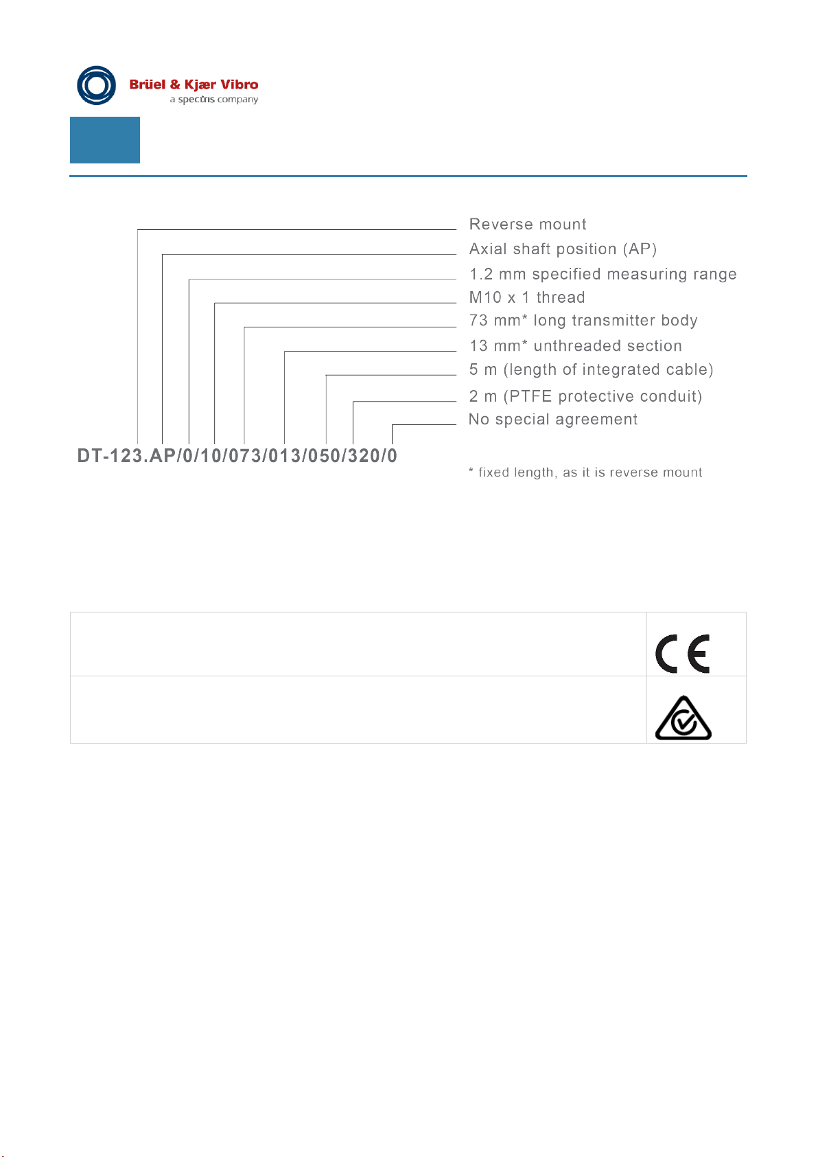
Order example
Approval / Declaration of Conformity
Displacement transmitter systems are:
CE Conformity as per EMC Directive
EN 61326-1: 2013
EN 50581: 2012
RCM for Australia and New Zeeland
Page 10 of 12
We reserve the right to make technical changes!
█ © Brüel & Kjaer Vibro ● September 2019 ● BPS0157-EN-13
Page 11

© Brüel & Kjaer Vibro │ Product specification
Transmitter Series DT-120
Approval / Declaration of Conformity
EN
© Brüel & Kjaer Vibro ● September 2019 ● BPS0157-EN-13 ● █ Page 11 of 12
We reserve the right to make technical changes!
Page 12

Contact details
Brüel & Kjaer Vibro GmbH
Leydheckerstrasse 10
64293 Darmstadt
Germany
Telephone: +49 6151 428 0
Fax: +49 6151 428 1000
Transmitter Series DT-120 ● BPS0157-EN-13 ● © Brüel & Kjaer Vibro ●
We reserve the right to make technical changes!
 Loading...